Embed Size (px)
Citation preview
1
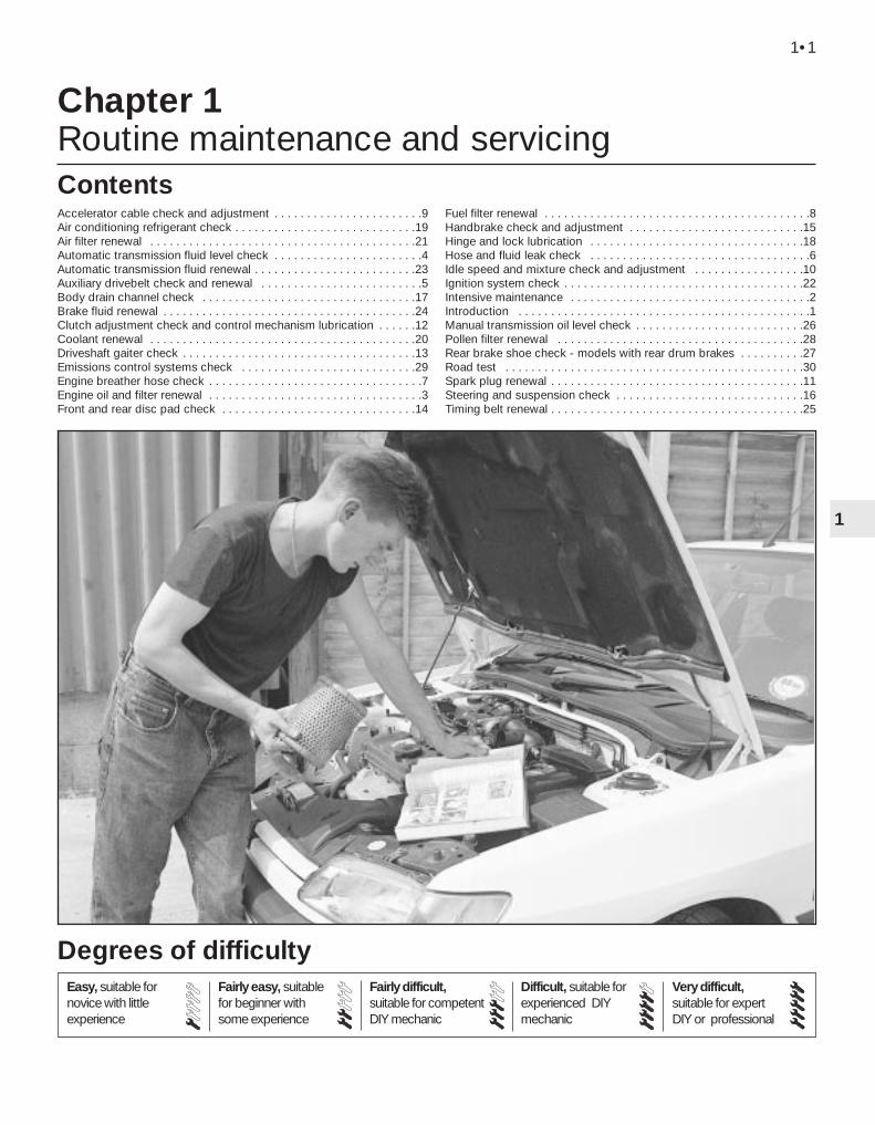
Chapter 1 Routine maintenance and servicing
Accelerator cable check and adjustment . . . . . . . . . . . . . . . . . . . . . . .9Air conditioning refrigerant check . . . . . . . . . . . . . . . . . . . . . . . . . . . .19Air filter renewal . . . . . . . . . . . . . . . . . . . . . . . . . . . . . . . . . . . . . . . . .21Automatic transmission fluid level check . . . . . . . . . . . . . . . . . . . . . . .4Automatic transmission fluid renewal . . . . . . . . . . . . . . . . . . . . . . . . .23Auxiliary drivebelt check and renewal . . . . . . . . . . . . . . . . . . . . . . . . .5Body drain channel check . . . . . . . . . . . . . . . . . . . . . . . . . . . . . . . . .17Brake fluid renewal . . . . . . . . . . . . . . . . . . . . . . . . . . . . . . . . . . . . . . .24Clutch adjustment check and control mechanism lubrication . . . . . .12Coolant renewal . . . . . . . . . . . . . . . . . . . . . . . . . . . . . . . . . . . . . . . . .20Driveshaft gaiter check . . . . . . . . . . . . . . . . . . . . . . . . . . . . . . . . . . . .13Emissions control systems check . . . . . . . . . . . . . . . . . . . . . . . . . . .29Engine breather hose check . . . . . . . . . . . . . . . . . . . . . . . . . . . . . . . . .7Engine oil and filter renewal . . . . . . . . . . . . . . . . . . . . . . . . . . . . . . . . .3Front and rear disc pad check . . . . . . . . . . . . . . . . . . . . . . . . . . . . . .14
Fuel filter renewal . . . . . . . . . . . . . . . . . . . . . . . . . . . . . . . . . . . . . . . . .8Handbrake check and adjustment . . . . . . . . . . . . . . . . . . . . . . . . . . .15Hinge and lock lubrication . . . . . . . . . . . . . . . . . . . . . . . . . . . . . . . . .18Hose and fluid leak check . . . . . . . . . . . . . . . . . . . . . . . . . . . . . . . . . .6Idle speed and mixture check and adjustment . . . . . . . . . . . . . . . . .10Ignition system check . . . . . . . . . . . . . . . . . . . . . . . . . . . . . . . . . . . . .22Intensive maintenance . . . . . . . . . . . . . . . . . . . . . . . . . . . . . . . . . . . . .2Introduction . . . . . . . . . . . . . . . . . . . . . . . . . . . . . . . . . . . . . . . . . . . . .1Manual transmission oil level check . . . . . . . . . . . . . . . . . . . . . . . . . .26Pollen filter renewal . . . . . . . . . . . . . . . . . . . . . . . . . . . . . . . . . . . . . .28Rear brake shoe check - models with rear drum brakes . . . . . . . . . .27Road test . . . . . . . . . . . . . . . . . . . . . . . . . . . . . . . . . . . . . . . . . . . . . .30Spark plug renewal . . . . . . . . . . . . . . . . . . . . . . . . . . . . . . . . . . . . . . .11Steering and suspension check . . . . . . . . . . . . . . . . . . . . . . . . . . . . .16Timing belt renewal . . . . . . . . . . . . . . . . . . . . . . . . . . . . . . . . . . . . . . .25
1•1
Easy, suitable fornovice with littleexperience
Fairly easy, suitablefor beginner withsome experience
Fairly difficult,suitable for competentDIY mechanic
Difficult, suitable forexperienced DIYmechanic
Very difficult,suitable for expertDIY or professional
Degrees of difficulty
Contents

Lubricants and fluidsRefer to the end of “Weekly checks”
Capacities
Engine oilTU engine - with filter . . . . . . . . . . . . . . . . . . . . . . . . . . . . . . . . . . . . . . . 3.5 litresTU engine - without filter . . . . . . . . . . . . . . . . . . . . . . . . . . . . . . . . . . . . 3.2 litresXU engine (8-valve) - with filter . . . . . . . . . . . . . . . . . . . . . . . . . . . . . . . . 5.0 litresXU engine (8-valve) - without filter . . . . . . . . . . . . . . . . . . . . . . . . . . . . . 4.5 litresXU engine (16-valve) - with filter . . . . . . . . . . . . . . . . . . . . . . . . . . . . . . . 5.3 litresXU engine (16-valve) - without filter . . . . . . . . . . . . . . . . . . . . . . . . . . . . 5.0 litresCooling system (approximate) . . . . . . . . . . . . . . . . . . . . . . . . . . . . . . . 7.0 litresManual gearbox . . . . . . . . . . . . . . . . . . . . . . . . . . . . . . . . . . . . . . . . . . 2.0 litresAutomatic transmission:
Drain and refill . . . . . . . . . . . . . . . . . . . . . . . . . . . . . . . . . . . . . . . . . . . 2.4 litresAfter overhaul . . . . . . . . . . . . . . . . . . . . . . . . . . . . . . . . . . . . . . . . . . . 6.2 litres
Power steering system . . . . . . . . . . . . . . . . . . . . . . . . . . . . . . . . . . . . . 0.7 litresFuel tank . . . . . . . . . . . . . . . . . . . . . . . . . . . . . . . . . . . . . . . . . . . . . . . . 70 litres
EngineOil filter type . . . . . . . . . . . . . . . . . . . . . . . . . . . . . . . . . . . . . . . . . . . . . . Champion F104
Cooling systemAntifreeze mixture:
28% antifreeze . . . . . . . . . . . . . . . . . . . . . . . . . . . . . . . . . . . . . . . . . . Protection down to -15°C(-5°F)50% antifreeze . . . . . . . . . . . . . . . . . . . . . . . . . . . . . . . . . . . . . . . . . . Protection down to -30°C(-22°F)
Fuel systemIdle speed:
TU carburettor engine . . . . . . . . . . . . . . . . . . . . . . . . . . . . . . . . . . . . 850 ± 50 rpmXU carburettor engine . . . . . . . . . . . . . . . . . . . . . . . . . . . . . . . . . . . . 900 ± 50 rpmXU5 and TU3 single-point injection (not adjustable) . . . . . . . . . . . . . 850 ± 50 rpmBosch L3.1 multi-point injection . . . . . . . . . . . . . . . . . . . . . . . . . . . . . 925 ± 25 rpmOther multi-point injection systems (not adjustable) . . . . . . . . . . . . . 850 ± 50 rpm
Idle mixture CO content:TU carburettor engine . . . . . . . . . . . . . . . . . . . . . . . . . . . . . . . . . . . . . 0.8%XU carburettor engine . . . . . . . . . . . . . . . . . . . . . . . . . . . . . . . . . . . . . 0.5%XU5 and TU3 single-point injection (not adjustable) . . . . . . . . . . . . . Less than 0.5 %XU5, XU7, XU9, XU10 multi-point injection (not adjustable) . . . . . . . Less than 1.0 %
Air filter element:TU engine . . . . . . . . . . . . . . . . . . . . . . . . . . . . . . . . . . . . . . . . . . . . . . Champion V401XU engine . . . . . . . . . . . . . . . . . . . . . . . . . . . . . . . . . . . . . . . . . . . . . . Champion U543
Fuel filter . . . . . . . . . . . . . . . . . . . . . . . . . . . . . . . . . . . . . . . . . . . . . . . . . Champion L101, L206, L132 or L135
Ignition systemSpark plugs:
TU and XU carburettor engines . . . . . . . . . . . . . . . . . . . . . . . . . . . . . Champion C9YCCXU injection 8-valve engines . . . . . . . . . . . . . . . . . . . . . . . . . . . . . . . . Champion C7YCCXU injection16-valve engines . . . . . . . . . . . . . . . . . . . . . . . . . . . . . . . Champion RC7BMC
Spark plug electrode gap*:8-valve engines . . . . . . . . . . . . . . . . . . . . . . . . . . . . . . . . . . . . . . . . . . 0.8 mm16-valve engines . . . . . . . . . . . . . . . . . . . . . . . . . . . . . . . . . . . . . . . . . 1.6 mm
Ignition HT lead resistance . . . . . . . . . . . . . . . . . . . . . . . . . . . . . . . . . . . Approximately 600 ohms per 100 mm length*The spark plug gap quoted is that recommended by Champion for their specified plugs listed above.
BrakesFront/rear brake pad friction material minimum thickness . . . . . . . . . . . 2.0 mmRear brake shoe friction material minimum thickness . . . . . . . . . . . . . . 1.0 mm
Tyre pressuresSee end of “Weekly Checks”.
Torque wrench settings Nm lbf ftEngine oil drain plug . . . . . . . . . . . . . . . . . . . . . . . . . . . . . . . . . . . . . . . . 27 20Manual gearbox drain plug . . . . . . . . . . . . . . . . . . . . . . . . . . . . . . . . . . 30 22Roadwheel bolts . . . . . . . . . . . . . . . . . . . . . . . . . . . . . . . . . . . . . . . . . . . 85 63Spark plugs . . . . . . . . . . . . . . . . . . . . . . . . . . . . . . . . . . . . . . . . . . . . . . . 27 20
1•2 Servicing Specifications

The maintenance intervals in this manualare provided with the assumption that you willbe carrying out the work yourself. These arethe minimum maintenance intervalsrecommended by the manufacturer forvehicles driven daily. If you wish to keep yourvehicle in peak condition at all times, you may
wish to perform some of these proceduresmore often. We encourage frequentmaintenance, because it enhances theefficiency, performance and resale value ofyour vehicle.
If the vehicle is driven in dusty areas, usedto tow a trailer, or driven frequently at slow
speeds (idling in traffic) or on short journeys,more frequent maintenance intervals arerecommended.
When the vehicle is new, it should beserviced by a factory-authorised dealerservice department, in order to preserve thefactory warranty.
Maintenance schedule - models up to 1993 1•3
1
Every 250 miles (400 km) or weeklymm Refer to “Weekly checks”
Every 12 000 miles (20 000 km) or 12 months - whichever comes soonerIn addition to all the items listed above, carry out the following:mm Check condition and security of engine breather
hoses (Section 7)mm Renew the fuel filter (Section 8)mm Check the condition of, and adjust as necessary,
the accelerator cable (Section 9)mm Check the idle speed and mixture (CO) adjustment.
Clean the fuel filter in the carburettor (whereapplicable) (Section 10)
mm Renew the spark plugs (Section 11)mm Check and adjust the clutch pedal travel
(Section 12)mm Check the condition of the driveshaft rubber gaiters
(Section 13)mm Check front and rear disc brake pads for wear
(Section 14)mm Check the operation of the handbrake and adjust
as necessary (Section 15)mm Check the steering and suspension components
(Section 16)mm Check and unblock all door and sill drain channels.
Also check the heater drain tube (Section 17)
Every 6000 miles (10 000 km) or 6 months - whichever comes soonermm Renew engine oil and filter (Section 3)mm Check the automatic transmission fluid level
(Section 4)mm Check the condition of the auxiliary drivebelt
(Section 5)mm Check all underbonnet components for fluid leaks
(Section 6)
Every 36 000 miles (60 000 km) or 3 years - whichever comes soonerIn addition to all the items listed above, carry out the following:mm Renew the timing belt (Section 25)mm Check and if necessary top-up the manual
transmission oil level (Section 26)mm Inspect the rear brake drum linings for wear
(Section 27)
Every 24 000 miles (40 000 km) or 2 years - whichever comes soonerIn addition to all the items listed above, carry out the following:mm Renew the coolant (Section 20)mm Renew the air filter element (Section 21)mm Check the ignition system and ignition timing
(Section 22)mm Renew the automatic transmission fluid
(Section 23)mm Renew the hydraulic fluid in the braking system
(Section 24)
Every 18 000 miles (30 000 km) or 18 months - whichever comes soonerIn addition to all the items listed above, carry out the following:mm Lubricate all hinges and locks (Section 18)mm Check the air conditioning system refrigerant
(Section 19)

The maintenance schedule for models from1994 is given below. When compared with theschedule for earlier models, it will be seen thatalthough the same operations are required, thefrequency with which they are performed haschanged considerably. The specified intervalfor most operations has been extended.
The description of the maintenance tasks inthis Chapter follows the schedule prescribed
for earlier models. When the interval for latermodels varies, this is of course indicated.However, the DIY owner may consider that itis well worth while observing the shorterintervals in any case.
We encourage frequent maintenance,because it enhances the efficiency,performance and ultimately, the resale valueof your vehicle.
If the vehicle is driven in dusty areas, isused to tow a trailer, or driven frequently atslow speeds (idling in traffic) or on shortjourneys, more frequent maintenance intervalsare recommended.
When the vehicle is new, it should beserviced by a factory-authorised dealerservice department, in order to preserve thefactory warranty.
1•4 Maintenance schedule - models from 1994
Every 250 miles (400 km) or weeklymm Refer to “Weekly checks”
Every 18 000 miles (30 000 km)In addition to all the items listed above, carry out the following:mm Check the air conditioning system refrigerant
(Section 19)mm Renew the spark plugs (Section 11)mm Renew the fuel filter - carburettor models
(Section 8)mm Renew the automatic transmission fluid
(Section 23)mm Check the ignition system and ignition timing
(Section 22)mm Check the idle speed and mixture adjustment
(Section 10)mm Check the emissions control system components
(Section 29)mm Check the condition of the auxiliary drivebelt
(Section 5)mm Lubricate the clutch control mechanism
(Section 12)mm Check the condition of the front brake pads
(Section 14)mm Check the operation of the handbrake (Section 15)mm Carry out a road test (Section 30)
Every 9000 miles (15 000 km) or 12 months - whichever comes soonerNote: It is strongly recommended that the engine oil and filter bechanged at least every 6 months, even if the mileage specified hasnot been covered.mm Renew engine oil and filter (Section 3)mm Check the clutch adjustment (Section 12)mm Check all underbonnet components for fluid leaks
(Section 6)mm Check the steering and suspension components
(Section 16)mm Check the condition of the driveshaft rubber gaiters
(Section 13)mm Check the automatic transmission fluid level
(Section 4)mm Renew the pollen filter where fitted (Section 28)
Every 72 000 miles (120 000 km)In addition to all the items listed above, carry out the following:mm Renew the timing belt (Section 25) - this is the
interval recommended by Peugeot, but werecommend that the belt is changed morefrequently, at 36 000 miles - see above.
Every 2 years (regardless of mileage)mm Renew the coolant (Section 20)mm Renew the brake fluid (Section 24)
Every 36 000 miles (60 000 km)In addition to all the items listed above, carry out the following:mm Lubricate all hinges and locks (Section 18)mm Renew the air filter (Section 21)mm Inspect the rear brake drum linings for wear
(Section 27)mm Check the condition of the rear disc brake pads
(Section 14)mm Check and if necessary top-up the manual
transmission oil level (Section 26)mm Renew the fuel filter - fuel injection models
(Section 8)mm Renew the timing belt (Section 25) see Note below.
Note: Although the normal interval for timing belt renewal is 72 000 miles (120 000 km), it is strongly recommended that theinterval is halved to 36 000 miles (60 000 km) on vehicles whichare subjected to intensive use, ie. mainly short journeys or a lotof stop-start driving. The actual belt renewal interval istherefore very much up to the individual owner, but bear inmind that severe engine damage will result if the belt breaks.

Maintenance & Servicing 1•5
1
Underbonnet view of a 1580 cc carburettor engine
1 Left-hand suspension strut top mounting
2 Battery3 Air filter housing4 Cold air inlet duct5 Bonnet lock6 Bonnet release latch7 Engine oil filler cap/tube8 Carburettor air inlet duct
(carburettor below)9 Radiator (coolant filler) cap10 Alternator11 Right-hand engine mounting12 Timing belt upper cover13 Right-hand suspension strut
top mounting14 Windscreen wash reservoir15 Brake hydraulic fluid reservoir16 Camshaft cover17 Windscreen wiper motor
(beneath cover)18 Hot air inlet duct19 Engine oil level dipstick20 Fuel pump21 Distributor22 Spark plug HT leads
Underbonnet view of a 1580 cc fuel injection engine
1 Brake hydraulic fluid reservoir2 Valve cover3 Windscreen wiper motor
(beneath cover)4 Engine oil level dipstick5 Hot air duct6 Left-hand suspension strut
top mounting7 Battery8 Power steering fluid reservoir9 Air cleaner10 Engine oil filler cap/tube11 Radiator (coolant filler) cap12 Alternator13 Right-hand engine mounting14 Windscreen washer reservoir

1•6 Maintenance & Servicing
Underbonnet view of a 1998 cc engine
1 Brake system hydraulic fluid reservoir
2 Engine oil filler cap3 Windscreen wiper motor
(below cover)4 Air cleaner cover5 Ignition coil6 Left-hand suspension strut
top mounting7 Battery8 Power steering fluid reservoir9 Inlet air duct10 Engine oil level dipstick11 Automatic transmission
kickdown cable12 Throttle housing13 Accelerator cable14 Radiator (coolant filler cap)15 Auxiliary drivebelt16 Windscreen washer fluid
reservoir
Underbonnet view of a 1905 cc engine
1 Left-hand strut top mounting2 Battery3 Fuel damper4 Power steering fluid reservoir5 Air filter cover6 Fuel injection control unit7 Thermostat housing8 Cold air inlet9 Throttle housing10 Brake servo vacuum hose11 Bonnet lock12 Inlet manifold13 Bonnet release latch14 Accelerator cable15 Radiator (coolant filler cap)16 Alternator17 Right-hand engine mounting18 Fuel injection relay box19 Right-hand strut top mounting20 Camshaft drivebelt top cover21 Fuel pressure regulator22 Engine oil filler tube23 Earth lead24 Windscreen washer reservoir25 Brake hydraulic fluid reservoir26 Brake servo vacuum unit27 Windscreen wiper motor 28 Fuel rail and injectors29 Camshaft cover30 Power steering hose31 Engine oil level dipstick32 Windscreen wiper arm33 Air inlet grille (ventilation)34 Distributor

Maintenance & Servicing 1•7
1
Rear underbody view of a 1905 cc engine model
1 Fuel tank2 Fuel tank supporting strap3 Heat shield4 Exhaust pipe5 Rear suspension side member6 Handbrake cable equaliser
mechanism7 Rear suspension torsion bar8 Rear shock absorber9 Rear disc brake caliper10 Exhaust rear silencer11 Spare wheel (cover removed)12 Spare wheel cradle support
hook13 Fuel filler hose14 Rear anti-roll bar15 Suspension cross-link
Front underbody view of a 1905 cc engine model
1 Fuel lines2 Front exhaust silencer3 Brake lines4 Front subframe rear mounting5 Steering rack mountings6 Exhaust downpipe7 Steering tack rod8 Lower suspension arm9 Radiator lower hose10 Engine oil sump11 Rear engine mounting12 Driveshaft intermediate
bearing housing13 Right-hand driveshaft14 Oil temperature sensor15 Engine oil drain plug16 Radiator17 Transmission housing18 Differential housing19 Cooling fan resistor20 Horn

Maintenance procedures
1•8 6000 Mile / 6 Month Service
1 Introduction
General information1 This Chapter is designed to help the homemechanic maintain his/her vehicle for safety,economy, long life and peak performance.2 The Chapter contains a mastermaintenance schedule, followed by Sectionsdealing specifically with each task in theschedule. Visual checks, adjustments,component renewal and other helpful itemsare included. Refer to the accompanyingillustrations of the engine compartment andthe underside of the vehicle for the locationsof the various components.3 Servicing your vehicle in accordance withthe mileage/time maintenance schedule andthe following Sections will provide a plannedmaintenance programme, which should resultin a long and reliable service life. This is acomprehensive plan, so maintaining someitems but not others at the specified serviceintervals, will not produce the same results.4 As you service your vehicle, you willdiscover that many of the procedures can -and should - be grouped together, because ofthe particular procedure being performed, orbecause of the close proximity of twootherwise-unrelated components to oneanother. For example, if the vehicle is raisedfor any reason, the exhaust can be inspectedat the same time as the suspension andsteering components.5 The first step in this maintenance
programme is to prepare yourself before theactual work begins. Read through all theSections relevant to the work to be carriedout, then make a list and gather together allthe parts and tools required. If a problem isencountered, seek advice from a partsspecialist, or a dealer service department.
2 Intensive maintenance
1 If, from the time the vehicle is new, theroutine maintenance schedule is followedclosely, and frequent checks are made of fluidlevels and high-wear items, as suggestedthroughout this manual, the engine will bekept in relatively good running condition, andthe need for additional work will be minimised.2 It is possible that there will be times whenthe engine is running poorly due to the lack ofregular maintenance. This is even more likelyif a used vehicle, which has not receivedregular and frequent maintenance checks, ispurchased. In such cases, additional workmay need to be carried out, outside of theregular maintenance intervals.3 If engine wear is suspected, a compressiontest will provide valuable informationregarding the overall performance of the maininternal components. Such a test can be usedas a basis to decide on the extent of the workto be carried out. If, for example, acompression test indicates serious internalengine wear, conventional maintenance asdescribed in this Chapter will not greatlyimprove the performance of the engine, and
may prove a waste of time and money, unlessextensive overhaul work is carried out first.4 The following series of operations are thosemost often required to improve theperformance of a generally poor-runningengine:
Primary operationsa) Clean, inspect and test the battery (see
“Weekly checks”).b) Check all the engine-related fluids (see
“Weekly checks”).c) Check the condition and tension of the
auxiliary drivebelt (Section 5).d) Renew the spark plugs (Section 11).e) Inspect the distributor cap and HT leads -
as applicable (Section 22).f) Check the condition of the air cleaner
filter element, and renew if necessary(Section 21).
g) Renew the fuel filter (Section 8).h) Check the condition of all hoses, and
check for fluid leaks (Section 6).i) Check the idle speed and mixture settings
- as applicable (Section 10).
5 If the above operations do not prove fullyeffective, carry out the following secondaryoperations:
Secondary operationsa) Check the charging system (Chapter 5A).b) Check the ignition system (Chapter 5B).c) Check the fuel system (Chapter 4).d) Renew the distributor cap and rotor arm -
as applicable (Chapter 5B).e) Renew the ignition HT leads - as
applicable (Section 22).
6000 Mile / 6 Month Service
3 Engine oil and filter renewal 1Note: On models from 1994, the maker’sspecified interval for this procedure is 9000 miles (15 000 km) or 12 months.Note: A suitable square-section wrench maybe required to undo the sump drain plug onsome models. These wrenches cab beobtained from most motor factors or yourPeugeot dealer.1 Frequent oil and filter changes are the mostimportant preventative maintenanceprocedures which can be undertaken by theDIY owner. As engine oil ages, it becomesdiluted and contaminated, which leads topremature engine wear.2 Before starting this procedure, gathertogether all the necessary tools and materials.
Also make sure that you have plenty of cleanrags and newspapers handy, to mop up anyspills. Ideally, the engine oil should be warm,as it will drain better, and more built-upsludge will be removed with it. Take care,however, not to touch the exhaust or anyother hot parts of the engine when workingunder the vehicle. To avoid any possibility ofscalding, and to protect yourself frompossible skin irritants and other harmfulcontaminants in used engine oils, it isadvisable to wear gloves when carrying outthis work. Access to the underside of thevehicle will be greatly improved if it can beraised on a lift, driven onto ramps, or jackedup and supported on axle stands (see“Jacking and Vehicle Support”). Whichevermethod is chosen, make sure that the vehicleremains level, or if it is at an angle, so that thedrain plug is at the lowest point. Wherenecessary remove the splash guard fromunder the engine.
3 Slacken the drain plug about half a turn; onsome models, a square-section wrench maybe needed to slacken the plug (seeillustration). Position the draining containerunder the drain plug, then remove the plugcompletely. If possible, try to keep the plug
3.3 Slackening the sump drain plug with asquare-section wrench

pressed into the sump while unscrewing it byhand the last couple of turns (see HaynesHint) .4 Recover the sealing ring from the drainplug.5 Allow some time for the old oil to drain,noting that it may be necessary to repositionthe container as the oil flow slows to a trickle.6 After all the oil has drained, wipe off thedrain plug with a clean rag. Check the sealingwasher for condition, and renew it ifnecessary. Clean the area around the drainplug opening, then refit and tighten the plug.7 If the filter is also to be renewed, move thecontainer into position under the oil filterwhich is located on the front side of thecylinder block, below the inlet manifold.8 Using an oil filter removal tool if necessary,slacken the filter initially, then unscrew it byhand the rest of the way (see illustration).Empty the oil from the old filter into thecontainer, and discard the filter.9 Use a clean rag to remove all oil, dirt andsludge from the filter sealing area on theengine. Check the old filter to make sure thatthe rubber sealing ring hasn’t stuck to theengine. If it has, carefully remove it.10 Apply a light coating of clean engine oil tothe sealing ring on the new filter, then screw itinto position on the engine. Tighten the filterfirmly by hand only - do not use any tools.Wipe clean the filter and sump drain plug.
11 Remove the old oil and all tools fromunder the car, then lower the car to theground (if applicable).12 Remove the dipstick then unscrew the oilfiller cap from the cylinder head cover. Fill theengine, using the correct grade and type of oil(see “Weekly checks”). An oil can spout orfunnel may help to reduce spillage. Pour inhalf the specified quantity of oil first, then waita few minutes for the oil to fall to the sump.Continue adding oil a small quantity at a timeuntil the level is up to the lower mark on thedipstick. Finally, bring the level up to theupper mark on the dipstick. Insert thedipstick, and refit the filler cap.13 Start the engine and run it for a fewminutes; check for leaks around the oil filterseal and the sump drain plug. Note that theremay be a delay of a few seconds before the oilpressure warning light goes out when theengine is first started, as the oil circulatesthrough the engine oil galleries and the new oilfilter, before the pressure builds up.14 Switch off the engine, and wait a fewminutes for the oil to settle in the sump oncemore. With the new oil circulated and the filtercompletely full, recheck the level on thedipstick, and add more oil as necessary.15 Dispose of the used engine oil safely, withreference to “General Repair Procedures” inthe Reference section of this manual.
4 Automatic transmission fluidlevel check 1
Note: On models from 1994, the maker’sspecified interval for this procedure is 9000 miles (15 000 km) or 12 months.1 Take the vehicle on a short journey, towarm the transmission up to normal operatingtemperature, then park the vehicle on levelground. The fluid level is checked using thedipstick located at the front of the enginecompartment, directly in front of theengine/transmission. The dipstick top isbrightly-coloured (usually orange) for easyidentification.2 With the engine idling and the selector leverin the “P” (Park) position, withdraw thedipstick from the tube, and wipe all the fluidfrom its end with a clean rag or paper towel.Insert the clean dipstick back into the tube asfar as it will go, then withdraw it once more.Note the fluid level on the end of the dipstick;it should be between the upper and lowermarks (see illustrations).
3 If topping-up is necessary, add the requiredquantity of the specified fluid to thetransmission via the dipstick tube. Use afunnel with a fine mesh gauze, to avoidspillage, and to ensure that no foreign matterenters the transmission. Note: Never overfillthe transmission so that the fluid level is abovethe upper mark.4 After topping-up, take the vehicle on ashort run to distribute the fresh fluid, thenrecheck the level again, topping-up ifnecessary.5 Always maintain the level between the twodipstick marks. If the level is allowed to fallbelow the lower mark, fluid starvation mayresult, which could lead to severetransmission damage.6 Frequent need for topping-up indicates thatthere is a leak, which should be found andcorrected before it becomes serious.
5 Auxiliary drivebelt check and renewal 3
Note: On models from 1994, the maker’sspecified interval for this procedure is 18 000 miles (30 000 km).Note: Peugeot specify the use of a specialelectronic tool (SEEM C.TRONIC type 105 belttensioning measuring tool) to correctly set theauxiliary drivebelt tension. If access to thisequipment cannot be obtained, anapproximate setting can be achieved usingthe method described below. If the methoddescribed is used, the tension should be
6000 Mile / 6 Month Service 1•9
4.2a Withdrawing the automatictransmission dipstick
4.2b Automatic transmission fluid dipsticklower (a) and upper (b) fluid level markings
3.8 Using an oil filter removal tool toslacken the oil filter
1
As the engine oil drain plug releasesfrom the threads, move it away sharplyso the stream of oil issuing from thesump runs into the container, not upyour sleeve!
Note: It isantisocial andillegal to dump oildown the drain.To find thelocation of yourlocal oil recyclingbank, call thisnumber free.

checked using the special electronic tool atthe earliest opportunity.1 Except for XU9J4 16-valve engines, allmodels are fitted with one auxiliary drivebeltdriven from the crankshaft pulley on the right-hand side of the engine. On non-airconditioning models the belt drives thealternator and power steering pump and itstension is adjusted manually. On models fittedwith air conditioning it drives the alternator,power steering pump and the air conditioningcompressor. On XU9J4 models a separatedrivebelt drives the power steering pump froma pulley on the end of the camshaft.
Checking the auxiliary drivebelt condition
Except XU9J4 16-valve power steering drivebelt2 Apply the handbrake, then jack up the frontof the car and support it on axle stands (see“Jacking and Vehicle Support”). Remove theright-hand front roadwheel.3 Remove the engine undercover andwheelarch cover as applicable.4 Using a suitable socket and extension barfitted to the crankshaft sprocket/pulley bolt,rotate the crankshaft so that the entire lengthof the drivebelt can be examined. Examine thedrivebelt for cracks, splitting, fraying ordamage. Check also for signs of glazing (shinypatches) and for separation of the belt plies.Renew the belt if worn or damaged.5 If the condition of the belt is satisfactory, onmodels where the belt is adjusted manually,check the drivebelt tension as describedbelow. On models with an automatic spring-loaded tensioner, there is no need to checkthe drivebelt tension.
XU9J4 16-valve power steering drivebelt6 The power steering drivebelt is positionedon the left-hand end of the cylinder head.Examine the full length of the drivebelt forcracks, splitting, fraying or damage. Ifnecessary turn the engine with a spanner onthe crankshaft pulley or by engaging 4th gearand pushing the car (for safety, the car mustbe on level ground). Check also for signs ofglazing (shiny patches) and for separation ofthe belt plies.7 If the condition of the belt is satisfactory,check the drivebelt tension as described laterin this Section.
Auxiliary drivebelt (early models) - removal,refitting and tensioning
Removal8 Loosen the alternator pivot and link bolts,then unscrew the adjuster bolt to release thedrivebelt tension (see illustration).9 Remove the drivebelt from the alternator,crankshaft and where necessary the powersteering pulleys.
Refitting and tensioning10 Locate the drivebelt on the pulleys makingsure it is correctly engaged with the grooves.11 The belt tension must be adjusted so thatwith moderate thumb pressure applied mid-way along the belt’s longest run, it can bedeflected by approximately 6.0 mm. Turn theadjuster bolt in or out to obtain the correcttension, then tighten the pivot and link bolts(see illustration).
Auxiliary drivebelt (models with a manually-adjusted tensioning pulley) -removal, refitting and tensioning
Removal12 If not already done, proceed as describedin paragraphs 2 and 3.13 Disconnect the battery negative lead.14 Slacken the tensioner pulley bracketadjustment/mounting bolts (one located in themiddle of the pulley and the other locatedbelow on the bracket (see illustration).15 Fully tighten the adjustment bolt to itsstop, then slip the drivebelt from the pulleys(see illustration).
Refitting16 If the belt is being renewed, ensure thatthe correct type is used. Fit the belt aroundthe pulleys, and take up the slack in the beltby tightening the adjuster bolt. Ensure that theribs on the belt are correctly engaged with thegrooves in the pulleys.17 Tension the drivebelt as described in thefollowing paragraphs.
Tensioning18 If not already done, proceed as describedin paragraphs 2 and 3.19 Correct tensioning of the drivebelt willensure that it has a long life. A belt which istoo slack will slip and perhaps squeal.Beware, however, of overtightening, as thiscan cause wear in the alternator bearings.20 The belt should be tensioned so that,under firm thumb pressure, there is approxi-mately 5.0 mm of free movement at the mid-point between the pulleys on the longest beltrun (see the note at the start of this Section).21 To adjust, unscrew the adjustment boltuntil the tension is correct, then rotate thecrankshaft a couple of times, and recheck thetension. Securely tighten the tensioner pulleybracket adjustment/mounting bolts.22 Reconnect the battery negative lead.23 Refit the engine undercover andwheelarch cover. Refit the roadwheel, andlower the vehicle to the ground.
Auxiliary drivebelt (models with an automaticspring-loaded tensioner pulley) -removal, refitting and tensioning
Removal24 If not already done, proceed as describedin paragraphs 2 and 3.25 Disconnect the battery negative lead.26 Using a square drive key in the squarehole in the bottom of the automatic adjusterbracket, turn the bracket anticlockwise torelease the tension on the belt. Hold thebracket in this position by inserting a 4.0 mm
1•10 6000 Mile / 6 Month Service
5.8 Loosening the alternator adjustmentbolts (early models)
5.14 Tensioner pulley bracket lowermounting bolt (arrowed)
5.15 Auxiliary drivebelt tension adjustmentbolt (arrowed)
5.11 Alternator drivebelt deflection (A)

Allen key through the special hole andtightening the peg.27 Unscrew the mounting bolts and removethe tensioner roller, then slip the auxiliarydrivebelt from the pulleys.28 Check that the tensioner pulleys turnfreely without any sign of roughness.
Refitting and tensioning29 If the belt is being renewed, ensure thatthe correct type is used. Fit the belt aroundthe pulleys making sure that it is engaged withthe correct grooves in the pulleys.30 Refit the tensioner roller and tighten themounting bolts.31 Using the square drive key hold theautomatic adjuster, then release the peg andslowly allow the tensioner to tighten the belt.Check again that the belt is correctly locatedin the pulley grooves.32 Reconnect the battery negative lead.33 Refit the engine undercover andwheelarch cover. Refit the roadwheel, andlower the vehicle to the ground.
Power steering pump drivebelt(XU9J4 16-valve) modelsRemoval34 Drain the hydraulic fluid from the systemas described in Chapter 10.35 Loosen the pump mounting bolts andremove the drivebelt.36 Disconnect the high and low pressureunions on the pump.
37 Remove the bolts and lift off the pump.
Refitting and tensioning38 Refit in reverse order, then tension thebelt by applying a torque of 55 Nm for a newbelt and 30 Nm for a used belt by using thesquare of a torque wrench in the square cut-out in the pump bracket, tightening themounting bolts while the torque tension ismaintained (see illustration).39 Fill and bleed the system (see Chapter 10).
6 Hose and fluid leak check 1Note: On models from 1994, the maker’sspecified interval for this procedure is9000 miles (15 000 km) or 12 months.1 Visually inspect the engine joint faces,gaskets and seals for any signs of water, oil orfuel leaks. Pay particular attention to the areasaround the camshaft cover, cylinder head, oilfilter and sump joint faces. Bear in mind that,over a period of time, some slight seepagefrom these areas is to be expected. What youare really looking for is any indication of aserious leak. Should a leak be found, renewthe offending gasket or oil seal by referring tothe appropriate Chapters in this manual.2 Also check the security and condition of allthe engine-related pipes and hoses. Ensurethat all cable-ties or securing clips are in placeand in good condition. Clips which are brokenor missing can lead to chafing of the hoses,pipes, or wiring, which could cause moreserious problems in the future.3 Carefully check the radiator hoses andheater hoses along their entire length. Renewany hose which is cracked, swollen, ordeteriorated. Cracks will show up better if thehose is squeezed. Pay close attention to thehose clips that secure the hoses to thecooling system components. Hose clips canpinch and puncture hoses, resulting in coolingsystem leaks. If the original Peugeot crimped-type hose clips are used, it may be a goodidea to replace them with standard worm-drive hose clips.
4 Inspect the cooling system (hoses, jointfaces, etc.) for leaks (see Haynes Hint).5 Where any problems of this nature arefound on system components, renew thecomponent or gasket, referring to Chapter 3.6 Where applicable, inspect the automatictransmission fluid cooler hoses for leaks ordeterioration.7 With the vehicle raised, inspect the petroltank and filler neck for punctures, cracks, andother damage. The connection between thefiller neck and tank is especially critical.Sometimes, a rubber filler neck or connectinghose will leak due to loose retaining clamps ordeteriorated rubber.8 Carefully check all rubber hoses and metalfuel lines leading away from the petrol tank.Check for loose connections, deterioratedhoses, crimped lines, and other damage. Payparticular attention to the vent pipes andhoses, which often loop up around the fillerneck, and can become blocked or crimped.Follow the lines to the front of the vehicle,carefully inspecting them all the way. Renewdamaged sections as necessary.9 From within the engine compartment,check the security of all fuel hose attachmentsand pipe unions, and inspect the fuel hosesand vacuum hoses for kinks, chafing anddeterioration.10 Where applicable, check the condition ofthe power steering fluid hoses and pipes.
6000 Mile / 6 Month Service 1•11
1
5.38 Square cut-out in power steeringpump bracket (a) on XU9J4 16-valve models A leak in the cooling system will usually
show up as white or rust coloureddeposits on the area adjoining the leak
12 000 Mile / 12 Month Service
7 Engine breather hose check 1Check the condition and security of all
engine breather hoses.Where the engine has covered a high
mileage, remove the hoses and clean anysludge from them.
8 Fuel filter renewal 2Note: On models from 1994, the maker’sspecified interval for this procedure is 18 000miles (30 000 km) for carburettor models, and36 000 miles (60 000 km) for fuel injectionmodels.
Carburettor models1 The fuel filter is connected into the fuelhose between the pump and the carburettorin the engine compartment (see illustration).2 To remove the filter, release the retainingclips and disconnect the fuel hoses from thefilter. Where the original Peugeot crimped-
Warning: Before carrying outthe following operation, refer tothe precautions in “Safety first!”and follow them implicitly.
Petrol is a highly-dangerous and volatileliquid, and the precautions necessarywhen handling it cannot be overstressed.

type hose clips are fitted, cut them off anddiscard them; use standard worm-drive hoseclips on refitting.3 Note the direction of the arrow marked onthe filter body. Unclip the filter from itsretaining bracket, and remove it from thevehicle.4 Connect the fuel hoses to the new filter.Make sure that the arrow on the filter body ispointing in the direction of the fuel flow, ie.towards the fuel pump. Secure the hoses inposition by securely tightening the retainingclips, then clip the filter back into position inits retaining bracket.5 At the same time, check the fuel reservoirtank on the side of the carburettor for sediment.Remove the reservoir as necessary for cleaning.6 The fuel connections on the reservoir are asfollows.a) Top hose - return to tank.b) Middle hose - supply from pump via filter.c) Lower hose - to carburettor inlet.
Fuel injection models7 The fuel filter is situated underneath the rearof the vehicle, mounted on the right-hand sideof the fuel tank. To gain access to the filter,chock the front wheels, then jack up the rearof the vehicle and support it on axle stands(see “Jacking and Vehicle Support”).8 Clamp the fuel hose on the tank side of thefilter. Bearing in mind the information given inthe relevant Part of Chapter 4 on depres-surising the fuel system, release the clips anddisconnect the fuel hoses from the filter. Beprepared for fuel spillage (see illustration).9 Note the direction of the arrow marked onthe filter body. Slacken the retaining clampscrew, then slide the filter out of the clamp,and remove it from underneath the vehicle.10 Dispose safely of the old filter; it will behighly-inflammable, and may explode ifthrown on a fire.11 Slide the new filter into position in theclamp, ensuring that the arrow on the filterbody is pointing in the direction of the fuelflow, ie. towards the throttle body/fuel rail.This can be determined by tracing the fuelhoses back along their length.12 Connect the fuel hoses to the filter, andsecure them in position with their retainingclips. Remove the hose clamp.
13 Start the engine, and check the filter hoseconnections for leaks. Lower the vehicle tothe ground on completion.
9 Accelerator cable check and adjustment 1
Refer to Chapter 4A or 4B.
10 Idle speed and mixturecheck and adjustment 3
Note: On models from 1994, the maker’sspecified interval for this procedure is 18 000 miles (30 000 km).1 Before checking the idle speed and mixturesetting, always check the following first:a) Check that (where adjustable) the ignition
timing is accurate (Chapter 5B).b) Check that the spark plugs are in good
condition and correctly gapped (Section 11).c) Check that the accelerator cable (and on
carburettor models, the choke cable) iscorrectly adjusted (refer to the relevantPart of Chapter 4).
d) Check that the crankcase breather hosesare secure, with no leaks or kinks(Sections 7 and 29).
e) Check that the air cleaner filter element isclean (Section 21).
f) Check that the exhaust system is in goodcondition (refer to the relevant Part ofChapter 4).
g) If the engine is running roughly, check thecompression pressures and valveclearances as described in Chapter 2.
h) On fuel injection models, check that thefuel injection/ignition system warning lightis not illuminated (refer to the relevantPart of Chapter 4).
2 Take the car on a journey of sufficientlength to warm it up to normal operatingtemperature. Note: Adjustment should ideallybe completed within two minutes of return,without stopping the engine. If the radiatorelectric cooling fan operates, wait for thecooling fan to stop. If adjustment takes longerthan stated, regularly clear any excess fuelfrom the inlet manifold by revving the enginetwo or three times to about 2000 rpm, thenallow it to idle again.
Carburettor models3 Ensure that all electrical loads are switchedoff, and that the choke lever is pushed fully in.If the car does not have a tachometer, connectone following its manufacturer’s instructions.Note the idle speed, and compare it with thatspecified. Note: Models with air conditioninghave an idle compensation device, and the airconditioning compressor must be runningwhile the idle speed is being checked andadjusted.4 Using a suitable flat-bladed screwdriver,screw in the idle adjusting screw (to increasethe speed) or out as necessary to obtain thespecified speed. The screw is located on thecarburettor on non-air conditioning models,and on the idle compensating device on airconditioning models (see illustrations).5 The idle mixture (exhaust gas CO level) isset at the factory, and should require nofurther adjustment. If, due to a change inengine characteristics (carbon build-up, borewear etc) or after a major carburettoroverhaul, the mixture becomes incorrect, itcan be reset. Note, however, that an exhaustgas analyser (CO meter) will be required tocheck the mixture, and to set it with thenecessary standard of accuracy. If this is notavailable, the car must be taken to a Peugeotdealer for the work to be carried out.6 Follow the exhaust gas analysermanufacturer’s instructions to check theexhaust gas CO level. If adjustment isrequired, it is made via mixture adjustment
1•12 12 000 Mile / 12 Month Service
8.1 Fuel filter location on carburettor models
10.4a Idle speed adjustment screw(arrowed) on models with idle compensation
10.4b Idle speed adjustment screw
8.8 Fuel filter on fuel injection modelsshowing fuel hoses (A) and clamp bolt (B)

screw located on the carburettor. The screwis covered with a tamperproof plug to preventunnecessary adjustment. To gain access tothe screw, use a sharp instrument to hook outthe plug.7 Using a suitable flat-bladed screwdriver,turn the mixture adjustment screw by verysmall amounts until the level is correct (seeillustration). Screwing it in (clockwise)weakens the idle mixture and reduces the COlevel; screwing it out will richen the mixtureand increase the CO level.8 When adjustments are complete, disconnectany test equipment, and fit a new tamperproofplug to the mixture adjustment screw. Recheckthe idle speed and, if necessary, readjust.
Fuel injection models
Bosch L3.1-Jetronic system9 Ensure that all electrical loads are switchedoff. If the car does not have a tachometer,connect one following its manufacturer’sinstructions. Note the idle speed, andcompare it with that specified.10 The idle speed is adjusted using the idlespeed adjustment screw on the throttlehousing (see illustration). Turn the screwclockwise to decrease the idle speed, or anti-clockwise to increase the speed.11 The idle mixture (exhaust gas CO level) isset at the factory, and should require nofurther adjustment. If, due to a change inengine characteristics (carbon build-up, borewear etc) or after a major overhaul, themixture becomes incorrect, it can be reset.Note, however, that an exhaust gas analyser
(CO meter) will be required to check themixture, and to set it with the necessarystandard of accuracy. If this is not available,the car must be taken to a Peugeot dealer forthe work to be carried out.12 Follow the exhaust gas analysermanufacturer’s instructions to check theexhaust gas CO level. If adjustment isrequired, it is made via mixture adjustmentscrew located on the airflow meter (seeChapter 4C). The screw may be covered witha tamperproof plug to prevent unnecessaryadjustment. To gain access to the screw, usea sharp instrument to hook out the plug.13 Using a flat-bladed screwdriver, turn themixture adjustment screw by small amountsuntil the level is correct (see illustration).14 When adjustments are complete, disconnectany test equipment, and fit a new tamperproofplug to the mixture adjustment screw. Recheckthe idle speed and, if necessary, readjust.
Bosch ML4.1 Motronic system15 The idle speed is non-adjustable. It iscontrolled by the idle speed regulator valve.16 The idle mixture (exhaust gas CO level) isset at the factory, and should require nofurther adjustment. If, due to a change inengine characteristics (carbon build-up, borewear etc) or after a major overhaul, themixture becomes incorrect, it can be reset.Note, however, that an exhaust gas analyser(CO meter) will be required to check themixture, and to set it with the necessarystandard of accuracy. If this is not available,the car must be taken to a Peugeot dealer forthe work to be carried out.
17 Follow the exhaust gas analysermanufacturer’s instructions to check theexhaust gas CO level. If adjustment isrequired, it is made via mixture adjustmentscrew located on the airflow meter (seeillustration). The screw may be covered witha tamperproof plug to prevent unnecessaryadjustment. To gain access to the screw, usea sharp instrument to hook out the plug.18 Turn the screw clockwise to increase andanti-clockwise to decrease CO content untilthe specified CO level is obtained.19 When adjustments are complete,disconnect any test equipment, and fit a newtamperproof plug to the mixture adjustmentscrew.
Bosch LU2-Jetronic system20 The idle mixture is not adjustable and isautomatically regulated by the ECU.21 To check the idle speed connect atachometer to the engine, then run the engineat idle speed.22 Turn the idle speed adjustment screw toobtain the specified idle speed (seeillustration).23 When adjustments are complete,disconnect any test gear from the engine.
Bosch Motronic MP3.1 system24 Ensure that all electrical loads areswitched off. If the car does not have atachometer, connect one following itsmanufacturer’s instructions. Note the idlespeed, and compare it with that specified.25 Turn the idle speed adjustment screw toobtain the specified idle speed (seeillustration).
12 000 Mile / 12 Month Service 1•13
10.13 Mixture (CO) adjustment screw onthe Bosch L3.1 injection control unit
10.25 Idle speed adjustment screw (1) onthe Bosch Motronic MP3.1 system
10.22 Idle speed adjustment screw (2) onthe Bosch LU2-Jetronic injection system
10.17 Mixture (CO) adjustment screw(arrowed) on Bosch ML4.1 Motronic system
10.10 Adjusting the idle speed screw onthe Bosch L3.1 injection system
1
10.7 Idle mixture adjustment screw(arrowed)

26 The idle mixture (exhaust gas CO level) isset at the factory, and should require nofurther adjustment. If, due to a change inengine characteristics (carbon build-up, borewear etc) or after a major overhaul, themixture becomes incorrect, it can be reset.Note, however, that an exhaust gas analyser(CO meter) will be required to check themixture, and to set it with the necessarystandard of accuracy. If this is not available,the car must be taken to a Peugeot dealer forthe work to be carried out.27 Follow the exhaust gas analysermanufacturer’s instructions to check theexhaust gas CO level. If adjustment isrequired, it is made via mixture adjustmentscrew (see illustration). The screw may becovered with a tamperproof plug to preventunnecessary adjustment. To gain access tothe screw, use a sharp instrument to hook outthe plug.28 Turn the screw clockwise to increase andanti-clockwise to decrease CO content untilthe specified CO level is obtained.29 When adjustments are complete,disconnect any test equipment, and fit a newtamperproof plug to the mixture adjustmentscrew.
Bosch Motronic M1.3 fuel injectionsystem30 The idle speed is only adjustable on theXU9JA/Z engine - on other engines it iscontrolled by the ECU and idle speed controlvalve.31 Ensure that all electrical loads areswitched off. If the car does not have atachometer, connect one following itsmanufacturer’s instructions. Note the idlespeed, and compare it with that specified.32 Turn the idle speed adjustment screw toobtain the specified idle speed (seeillustration).33 The idle mixture (CO) is only adjustable onthe XU9J4/K engine - on other engines it iscontrolled by the ECU.34 The idle mixture (exhaust gas CO level) isset at the factory, and should require nofurther adjustment. If, due to a change inengine characteristics (carbon build-up, borewear etc) or after a major overhaul, themixture becomes incorrect, it can be reset.Note, however, that an exhaust gas analyser
(CO meter) will be required to check themixture, and to set it with the necessarystandard of accuracy. If this is not available,the car must be taken to a Peugeot dealer forthe work to be carried out.35 Follow the exhaust gas analysermanufacturer’s instructions to check theexhaust gas CO level. If adjustment isrequired, it is made via mixture adjustmentscrew located on top of the airflow meterassembly (see illustration). The screw maybe covered with a tamperproof plug toprevent unnecessary adjustment. To gainaccess to the screw, use a sharp instrumentto hook out the plug.36 Turn the screw clockwise to increase andanti-clockwise to decrease CO content untilthe specified CO level is obtained.
All other fuel injection systems37 Experienced home mechanics, with aconsiderable amount of skill and equipment(including a tachometer and an accurateexhaust gas analyser) may be able to checkthe exhaust CO level and the idle speed.However, if these are found to be in need ofadjustment, the car must be taken to asuitably-equipped Peugeot dealer.38 On models with a Magneti Marelli enginemanagement (fuel injection/ignition) system,adjustment of the mixture setting (exhaust gasCO level) is possible, but adjustments canonly be made by reprogramming the enginemanagement ECU using special electronictest equipment which is connected to thediagnostic connector (see Chapter 4).39 On all other vehicles, adjustments are notpossible. If the idle speed or the exhaust gasCO level is incorrect, there must be a fault inthe engine management system, and thevehicle should be taken to a Peugeot dealerfor testing (see Chapter 4).
11 Spark plug renewal 2Note: On models from 1994, the maker’sspecified interval for this procedure is 18 000 miles (30 000 km).1 The correct functioning of the spark plugs isvital for the correct running and efficiency of
the engine. It is essential that the plugs fittedare appropriate for the engine (the suitabletype is specified at the beginning of thisChapter). If this type is used, and the engine isin good condition, the spark plugs should notneed attention between scheduledreplacement intervals. Spark plug cleaning israrely necessary, and should not beattempted unless specialised equipment isavailable, as damage can easily be caused tothe firing ends.2 On 16-valve models, to gain access to thespark plugs, the access cover fitted over thecentre of the cylinder head must first beremoved. Undo the eight bolts, noting theposition of the wiring retaining clip, andremove the cover (see illustration).3 On other models, to improve access tosome of the plugs, it may be necessary toremove the air inlet duct (refer to Chapter 4 forfurther information).4 On 1998 cc 16-valve models, pull the HTcoils off the spark plugs. If necessary, toremove the possibility of the HT coils beingconnected to the wrong spark plugs onrefitting, mark the coils 1 to 4 (No 1 cylinder isat the transmission end of the engine).5 On all other models, if the marks on theoriginal-equipment spark plug (HT) leadscannot be seen, mark the leads 1 to 4,corresponding to the cylinder the lead serves(No 1 cylinder is at the transmission end of theengine). Pull the leads from the plugs bygripping the end fitting, not the lead,otherwise the lead connection may befractured (see illustration).
1•14 12 000 Mile / 12 Month Service
10.27 Mixture (CO) adjustment screw (2)on the Bosch MP3.1 fuel injection system
10.35 Mixture adjustment screw (5) on theBosch Motronic M1.3 fuel injection system
11.2 On 16-valve models undo the eightbolts (arrowed) and remove the access
cover to reach the spark plugs
10.32 Idle speed adjustment screw (7) onthe Bosch Motronic M1.3 injection system

6 It is advisable to remove the dirt from thespark plug recesses, using a clean brush,vacuum cleaner or compressed air beforeremoving the plugs, to prevent dirt droppinginto the cylinders.7 Unscrew the plugs using a spark plugspanner, suitable box spanner, or a deepsocket and extension bar (see illustration).Keep the socket aligned with the spark plug -if it is forcibly moved to one side, the ceramicinsulator may be broken off. As each plug isremoved, examine it as follows.8 Examination of the spark plugs will give agood indication of the condition of the engine.If the insulator nose of the spark plug is cleanand white, with no deposits, this is indicativeof a weak mixture or too hot a plug (a hot plugtransfers heat away from the electrode slowly,a cold plug transfers heat away quickly).9 If the tip and insulator nose are coveredwith hard black-looking deposits, then this isindicative that the mixture is too rich. Shouldthe plug be black and oily, then it is likely thatthe engine is fairly worn, as well as the mixturebeing too rich.
10 If the insulator nose is covered with lighttan to greyish-brown deposits, then themixture is correct, and it is likely that theengine is in good condition.11 The spark plug electrode gap is ofconsiderable importance as, if it is too large ortoo small, the size of the spark and itsefficiency will be seriously impaired. The gapshould be set to the value given in the Specifi-cations at the beginning of this Chapter.12 To set the gap, measure it with a feelerblade, then bend the outer plug electrode untilthe correct gap is achieved (see illustration).The centre electrode should never be bent, asthis may crack the insulator and cause plugfailure, if nothing worse. If using feeler blades,the gap is correct when the appropriate-sizeblade is a firm, sliding fit.13 Special spark plug electrode gapadjusting tools are available from most motoraccessory shops, or from some spark plugmanufacturers.14 Before fitting the spark plugs, check thatthe threaded connector sleeves (on top of theplug) are tight, and that the plug exteriorsurfaces and threads are clean. It is very oftendifficult to insert spark plugs into their holeswithout cross-threading them. To avoid thispossibility, fit a short length of hose over theend of the spark plug (see Haynes Hint).15 Remove the rubber hose (if used), andtighten the plug to the specified torque (see“Specifications”) using the spark plug socketand a torque wrench. Refit the remainingplugs in the same way.16 Connect the HT leads in the correct order,and refit any components removed foraccess. On 1998 cc 16-valve models, connectthe HT coils in their correct order.
12 Clutch adjustment checkand control mechanismlubrication 2
Note: On models from 1994, the maker’sspecified interval for this procedure is 9000 miles (15 000 km) or 12 months for clutchadjustment, and 18 000 miles (30 000 km) forlubrication.1 Check that the clutch pedal movessmoothly and easily through its full travel.
2 The clutch itself should function correctly,with no trace of slip or drag.3 Where possible, adjust the clutch cable ifnecessary, as described in Chapter 6.4 If excessive effort is required to operate theclutch, check first that the cable is correctlyrouted and undamaged. Remove the pedal,and make sure that its pivot is properlygreased. Refer to Chapter 6 for furtherinformation.
13 Driveshaft gaiter check 1Note: On models from 1994, the maker’sspecified interval for this procedure is 9000 miles (15 000 km) or 12 months.
With the vehicle raised and securelysupported on stands, turn the steering ontofull lock, then slowly rotate the roadwheel.Inspect the condition of the outer constantvelocity (CV) joint rubber gaiters, whilesqueezing the gaiters to open out the folds(see illustration). Check for signs of cracking,splits, or deterioration of the rubber, whichmay allow the grease to escape, and lead towater and grit entry into the joint. Also checkthe security and condition of the retainingclips. Repeat these checks on the inner CVjoints. If any damage or deterioration is found,the gaiters should be renewed without delayas described in Chapter 8.
At the same time, check the generalcondition of the CV joints themselves, by firstholding the driveshaft and attempting to rotate
12 000 Mile / 12 Month Service 1•15
13.1 Check the condition of the driveshaftgaiters (arrowed)
11.12 Measuring the spark plug gap with afeeler blade
11.7 Tools required for spark plugremoval, gap adjustment and refitting
11.5 Pulling the HT leads from the spark plugs
1
It is often difficult to insert spark plugsinto their holes without cross-threadingthem. To avoid this possibility, fit ashort length of 5/16 inch internaldiameter rubber hose over the end ofthe spark plug. The flexible hose acts asa universal joint to help align the plugwith the plug hole. Should the plugbegin to cross-thread, the hose will slipon the spark plug, preventing threaddamage to the cylinder head.

the wheel. Repeat this check by holding theinner joint and attempting to rotate thedriveshaft. Any obvious movement indicateswear in the joints, wear in the driveshaft splines,or a loose driveshaft retaining nut.
14 Front and rear disc pad check 1
Note: On models from 1994, the maker’sspecified interval for this procedure is 18 000 miles (30 000 km) for the front brakepads, and 36 000 miles (60 000 km) for therear brake pads or shoes.1 Firmly apply the handbrake, then jack upthe front or rear of the car (as applicable) andsupport it securely on axle stands (see“Jacking and Vehicle Support”). Remove thefront or rear roadwheels.
2 If any pad’s friction material is worn to thespecified thickness or less, all four pads mustbe renewed as a set.3 For a comprehensive check, the brake padsshould be removed and cleaned. Theoperation of the caliper can then also bechecked, and the condition of the brake discitself can be fully examined on both sides.Refer to Chapter 9 for further information.
15 Handbrake check andadjustment 3
Note: On models from 1994, the maker’sspecified interval for this procedure is 9000 miles (15 000 km) or 12 months.
Refer to Chapter 9.
16 Steering and suspension check 2
Note: On models from 1994, the maker’sspecified interval for this procedure is 9000 miles (15 000 km) or 12 months.
Front suspension and steering check1 Raise the front of the car, and support on axlestands (see “Jacking and Vehicle Support”).
2 Inspect the balljoint dust covers and thesteering rack-and-pinion gaiters for splits,chafing or deterioration. Any wear of thesecomponents will cause loss of lubricant, withdirt and water entry, resulting in rapiddeterioration of the balljoints or steering gear.3 On vehicles with power steering, check thefluid hoses for chafing or deterioration, andthe pipe and hose unions for fluid leaks. Alsocheck for signs of fluid leakage underpressure from the steering gear rubbergaiters, which would indicate failed fluid sealswithin the steering gear.4 Grasp the roadwheel at the 12 o’clock and 6 o’clock positions, and try to rock it (seeillustration). Very slight free play may be felt,but if the movement is appreciable, furtherinvestigation is necessary to determine thesource. Continue rocking the wheel while anassistant depresses the footbrake. If themovement is now eliminated or significantlyreduced, it is likely that the hub bearings areat fault. If the free play is still evident with thefootbrake depressed, then there is wear in thesuspension joints or mountings.5 Now grasp the wheel at the 9 o’clock and 3 o’clock positions, and try to rock it asbefore. Any movement felt now may again becaused by wear in the hub bearings or thesteering track-rod balljoints. If the outerballjoint is worn, the visual movement will beobvious. If the inner joint is suspect, it can befelt by placing a hand over the rack-and-pinionrubber gaiter and gripping the track-rod. If thewheel is now rocked, movement will be felt atthe inner joint if wear has taken place.6 Using a large screwdriver or flat bar, checkfor wear in the suspension mounting bushesby levering between the relevant suspensioncomponent and its attachment point. Somemovement is to be expected, as themountings are made of rubber, but excessivewear should be obvious. Also check thecondition of any visible rubber bushes,looking for splits, cracks or contamination ofthe rubber.7 With the car standing on its wheels, have anassistant turn the steering wheel back andforth, about an eighth of a turn each way.There should be very little, if any, lostmovement between the steering wheel androadwheels. If this is not the case, closelyobserve the joints and mountings previouslydescribed. In addition, check the steeringcolumn universal joints for wear, and alsocheck the rack-and-pinion steering gear itself.
Rear suspension check8 Chock the front wheels, then jack up therear of the car and support on axle stands(see “Jacking and Vehicle Support”).
9 Working as described previously for thefront suspension, check the rear hubbearings, the suspension bushes and theshock absorber mountings for wear.
Suspension strut/shock absorber check10 Check for any signs of fluid leakagearound the suspension strut/shock absorberbody, or from the rubber gaiter around thepiston rod. Should any fluid be noticed, thesuspension strut/shock absorber is defectiveinternally, and should be renewed. Note:Suspension struts/shock absorbers shouldalways be renewed in pairs on the same axle.11 The efficiency of the suspensionstrut/shock absorber may be checked bybouncing the vehicle at each corner.Generally speaking, the body will return to itsnormal position and stop after beingdepressed. If it rises and returns on arebound, the suspension strut/shockabsorber is probably suspect. Examine alsothe suspension strut/shock absorber upperand lower mountings for any signs of wear.
17 Body drain channel check 1Check and unblock all door and sill drain
channels. Also check the heater drain tubelocated at the rear of the enginecompartment.
1•16 12 000 Mile / 12 Month Service
16.4 Check for wear in the hub bearingsby grasping the wheel and trying to rock it
For a quick check, thethickness of friction materialremaining on each brake padcan be measured through
the aperture in the caliper body.

20 Coolant renewal 2Note: On models from 1994, the maker’sspecified interval for this procedure is every 2 years, regardless of mileage.
Cooling system draining
1 With the engine completely cold, removethe expansion tank filler cap. Turn the capanti-clockwise until it reaches the first stop.Wait until any pressure remaining in the
system is released, then push the cap down,turn it anti-clockwise to the second stop, andlift it off.2 Position a suitable container beneath thecoolant drain outlet at the lower left-hand sideof the radiator.3 Loosen the drain plug (there is no need toremove it completely) and allow the coolant todrain into the container. If desired, a length oftubing can be fitted to the drain outlet todirect the flow of coolant during draining (seeillustration).
4 To assist draining, open the cooling systembleed screws. On all except 1.4 litre engines,the bleed screws are located in the thermostatcover and thermostat housing. On 1.4 litreengines, the bleed screws are located in thethermostat housing, and in the cylinder headcoolant bypass hose. Additionally, on 2.0 litreXU10J4 engines, there is a bleed screwlocated in the coolant bypass hose behind thecylinder head. All models also have a bleedscrew located at the top left-hand corner ofthe radiator (see illustrations).
18 Hinge and lock lubrication 1Note: On models from 1994, the maker’sspecified interval for this procedure is 36 000 miles (60 000 km).1 Work around the vehicle, and lubricate thehinges of the bonnet, doors and tailgate with alight machine oil.2 Lightly lubricate the bonnet releasemechanism and exposed section of innercable with a smear of grease.3 Check carefully the security and operationof all hinges, latches and locks, adjustingthem where required. Check the operation ofthe central locking system (if fitted).4 Check the condition and operation of thetailgate struts, renewing them if either isleaking or is no longer able to support thetailgate securely when raised.
19 Air conditioning refrigerantcheck 1
Note: On models from 1994, the maker’sspecified interval for this procedure is 18 000 miles (30 000 km).
1 In order to check the condition of therefrigerant, a humidity indicator and a sightglass are provided on top of the drier bottle,located in the front, left-hand corner of theengine compartment (see illustration).
Refrigerant humidity check2 Check the colour of the humidity indicator.Blue indicates that the condition of therefrigerant is satisfactory. Pink indicates that
the refrigerant is saturated with humidity. Ifthe indicator shows red, the system should bedrained and recharged, and a new drier bottleshould be fitted. Note: The system should bedrained and recharged only by a Peugeotdealer or air conditioning specialist. Do notattempt to carry out the work yourself, as therefrigerant is a highly-dangerous substance(refer to Chapter 3).
Refrigerant flow check3 Run the engine, and switch on the airconditioning.4 After a few minutes, inspect the sight glass,and check the fluid flow. Clear fluid should bevisible - if not, the following will help todiagnose the problem:
a) Clear fluid flow - the system is functioningcorrectly.
b) No fluid flow - have the system checkedfor leaks by a Peugeot dealer or airconditioning specialist.
c) Continuous stream of clear air bubbles influid - refrigerant level low - have thesystem recharged by a Peugeot dealer orair conditioning specialist.
d) Milky air bubbles visible - high humidity(see paragraph 2).
18 000 Mile / 18 Month Service
18 000 Mile / 18 Month Service 1•17
20.4a Cooling system bleed screws onthermostat housing and cover (arrowed) -
1.6 litre engine shown
19.1 Air conditioning system drier bottlesight glass (1) and humidity indicator (2)
20.3 Radiator drain outlet (arrowed)
1
Warning: Do not attempt toopen the refrigerant circuit.Refer to the precautions givenin Chapter 3.
24 000 Mile / 2 Year Service
Warning: Wait until the engine iscold before starting thisprocedure. Do not allowantifreeze to come in contact
with your skin, or with the paintedsurfaces of the vehicle. Rinse off spillsimmediately with plenty of water. Neverleave antifreeze lying around in an opencontainer, or in a puddle in the drivewayor on the garage floor. Children and petsare attracted by its sweet smell, butantifreeze can be fatal if ingested.

5 On 1.4 litre and 2.0 litre engines, when theflow of coolant stops, reposition the containerbelow the cylinder block drain plug. On 1.4 litre engines, the drain plug is located atthe front left-hand end of the cylinder block. On 2.0 litre engines, the drain plug islocated at the rear left-hand end of thecylinder block, next to the rear enginemounting (see illustrations). On 1.6, 1.8 and1.9 litre engines, no cylinder block drain plugis fitted.6 Where applicable, remove the cylinderblock drain plug, and allow the coolant todrain into the container.7 If the coolant has been drained for a reasonother than renewal, then provided it is cleanand less than two years old, it can be re-used,though this is not recommended.8 Refit and tighten the radiator and cylinderblock drain plugs, as applicable, oncompletion of draining.
Cooling system flushing9 If coolant renewal has been neglected, or ifthe antifreeze mixture has become diluted,then in time, the cooling system may graduallylose efficiency, as the coolant passagesbecome restricted due to rust, scale deposits,and other sediment. The cooling systemefficiency can be restored by flushing thesystem clean.10 The radiator should be flushedindependently of the engine, to avoidunnecessary contamination.
Radiator flushing11 To flush the radiator, first tighten the
radiator drain plug, and the radiator bleedscrew, where applicable.12 Disconnect the top and bottom hoses andany other relevant hoses from the radiator,with reference to Chapter 3.13 Insert a garden hose into the radiator topinlet. Direct a flow of clean water through theradiator, and continue flushing until cleanwater emerges from the radiator bottomoutlet.14 If after a reasonable period, the water stilldoes not run clear, the radiator can be flushedwith a good proprietary cleaning agent. It isimportant that the manufacturer’s instructionsare followed carefully. If the contamination isparticularly bad, insert the hose in the radiatorbottom outlet, and reverse-flush the radiator.
Engine flushing15 To flush the engine, first refit and tightenthe cylinder block drain plug (whereapplicable), and tighten the cooling systembleed screws.16 Remove the thermostat as described inChapter 3, then temporarily refit thethermostat cover.17 With the top and bottom hosesdisconnected from the radiator (see Chapter 3- it may be preferable to disconnect thebottom hose from the engine), insert a gardenhose into the radiator top hose. Direct a cleanflow of water through the engine, andcontinue flushing until clean water emergesfrom the radiator bottom hose.18 On completion of flushing, refit thethermostat and reconnect the hoses withreference to Chapter 3.
Cooling system filling19 Before attempting to fill the coolingsystem, make sure that all hoses and clips arein good condition, and that the clips are tight.Note that an antifreeze mixture must be usedall year round, to prevent corrosion of theengine components (see following sub-Section). Also check that the radiator andcylinder block drain plugs, as applicable, arein place and tight.20 Remove the expansion tank cap.21 Open all the cooling system bleed screws(see paragraph 4).22 Some of the cooling system hoses arepositioned at a higher level than the top of theradiator expansion tank. It is thereforenecessary to use a “header tank” whenrefilling the cooling system, to reduce thepossibility of air being trapped in the system.Although Peugeot dealers use a specialheader tank, the same effect can be achievedby using a suitable bottle, with a seal betweenthe bottle and the expansion tank (seeillustration and Haynes Hint).23 Fit the “header tank” to the expansiontank and slowly fill the system. Coolant willemerge from each of the bleed screws in turn,starting with the lowest screw. As soon ascoolant free from air bubbles emerges fromthe lowest screw, tighten that screw, andwatch the next bleed screw in the system.Repeat the procedure until the coolant is
1•18 24 000 Mile / 2 Year Service
20.4b Coolant bypass hose bleed screw(arrowed) - 1.4 litre engine
20.5a Cylinder block drain plug location(arrowed) - 1.4 litre engine
20.22 Peugeot cooling system “header tank” in position
20.5b Cylinder block drain plug location(arrowed) - 2.0 litre engine
20.4c Radiator bleed screw (arrowed)
Cut the bottom off an old antifreezecontainer to make a ‘header tank’ foruse when refilling the cooling system.The seal at the point arrowed must beas airtight as possible

emerging from the highest bleed screw in thecooling system and all bleed screws aresecurely tightened. Keep the “header tank”full during this procedure.24 Once all the bleed screws are securelytightened, remove the “header tank” and refitthe expansion tank cap.25 Start the engine, and run it at 1500 rpm.Maintain this engine speed until the radiatorcooling fan has cut in and out three times.26 Allow the engine to run at idle speed for afew minutes.27 Stop the engine, and wait for at least tenminutes.28 Place a large wad of rag around theexpansion tank cap, and around your hand,then carefully remove the expansion tank cap.Turn the cap anti-clockwise until it reachesthe first stop. Wait until any pressureremaining in the system is released, then pushthe cap down, turn it anti-clockwise to thesecond stop, and lift it off.
29 Check the coolant level, and if necessarytop-up the expansion tank to just above the“MAXI” level mark (see “Weekly checks”).30 Refit the expansion tank cap.
Antifreeze mixture31 The antifreeze should always be renewedat the specified intervals. This is necessarynot only to maintain the antifreeze properties,but also to prevent corrosion which wouldotherwise occur as the corrosion inhibitorsbecome progressively less effective.32 Always use an ethylene-glycol basedantifreeze which is suitable for use in mixed-metal cooling systems. The quantity ofantifreeze and levels of protection areindicated in the Specifications.33 Before adding antifreeze, the coolingsystem should be completely drained,preferably flushed, and all hoses checked forcondition and security.34 After filling with antifreeze, a label shouldbe attached to the expansion tank, stating thetype and concentration of antifreeze used,and the date installed. Any subsequenttopping-up should be made with the sametype and concentration of antifreeze.35 Do not use engine antifreeze in thewindscreen/tailgate washer system, as it willcause damage to the vehicle paintwork. Ascreenwash additive should be added to thewasher system in the quantities stated on thebottle.
21 Air filter renewal 2Note: On models from 1994, the maker’sspecified interval for this procedure is 36 000 miles (60 000 km).
TU models1 Slacken the retaining clips (where fitted),and disconnect the vacuum hose andbreather hose from the front of the air cleanerhousing-to-carburettor/throttle body duct(see illustration). Where the crimped-typePeugeot hose clips are fitted, cut the clips anddiscard them; use standard worm-drive hoseclips on refitting.2 Slacken the retaining clip securing the ductto the carburettor/throttle body. Release theretaining clips securing the lid to the top of theair cleaner housing. Lift the duct and aircleaner lid assembly away, and position itclear of the air cleaner housing (seeillustrations).3 Lift the air cleaner element out of thehousing (see illustration).4 Fit the new element into the housing, andsecure it in position with the retaining clips.5 Refit the sealing ring to the top of the filter
(where fitted), and refit the air cleaner-to-carburettor/throttle body duct. Ensure that theduct and its sealing rings are correctly seated,and securely tighten the retaining clips.6 Reconnect the vacuum and breather hosesto the duct, and secure them in position withthe retaining clips (where fitted).
XU models (except XU10J4 16-valve) with side-mounted air cleaner7 Disconnect the air duct from the filterhousing cover to the carburettor/airflow meterat the filter housing end (see illustration).8 Release the clips and lift off the air cleanertop cover (see illustration).9 Withdraw the filter element from the aircleaner body (see illustration).10 Fit the new element in position in the aircleaner body making sure that it is the rightway round.
24 000 Mile / 2 Year Service 1•19
21.2b . . . and remove the duct, positioningit clear of the air cleaner housing
21.8 Lifting off the top cover21.7 Air filter housing cover located in theleft-hand front of the engine compartment
21.3 Removing the air cleaner element on TU models
21.2a . . . then release the air cleaner lidretaining clips, and the duct clip . . .
21.1 On TU models disconnect the hosesfrom the front of the duct . . .
1
Warning: Take precautionsagainst scalding, as the coolingsystem will be hot.

11 Refit the top cover and attach the clips.12 Reconnect the air duct.
XU models (except XU10J4 16-valve) with top-mounted air cleaner13 Slacken the retaining clip, and disconnectthe inlet duct from the front of the cylinderhead cover (see illustration).14 Slacken and remove the two retainingscrews situated at the front of the cylinderhead cover, then release the two air filtercover retaining clips. Remove the filter coverfrom the cylinder head cover, and withdrawthe filter element (see illustrations).15 Fit the new element in position in thecylinder head cover. Refit the filter cover, andsecure it with its retaining screws and clips.16 Reconnect the inlet duct to the cylinderhead cover, and tighten its retaining clip.
XU10J4 16-valve models17 Disconnect the air duct and remove thecover from the end of the air cleaner body.18 Withdraw the air filter element notingwhich way round it is fitted.19 Fit the new element in the body, ensuringthat it is fitted the correct way round.20 Refit the cover and air duct.
22 Ignition system check 3Note: On models from 1994, the maker’sspecified interval for this procedure is 18 000 miles (30 000 km).
1 The ignition system components should bechecked for damage or deterioration asdescribed under the relevant sub-heading.
Ignition systems incorporating a distributorGeneral component check2 The spark plug (HT) leads should bechecked whenever new spark plugs areinstalled in the engine.3 Ensure that the leads are numbered beforeremoving them, to avoid confusion whenrefitting. Pull the leads from the plugs bygripping the end fitting, not the lead,otherwise the lead connection may befractured.4 Check inside the end fitting for signs ofcorrosion, which will look like a white crustypowder. Push the end fitting back onto thespark plug, ensuring that it is a tight fit on theplug. If not, remove the lead again, and usepliers to carefully crimp the metal connectorinside the end fitting until it fits securely on theend of the spark plug.5 Using a clean rag, wipe the entire length ofthe lead to remove any built-up dirt and
grease. Once the lead is clean, check forburns, cracks and other damage. Do not bendthe lead excessively, or pull the leadlengthways - the conductor inside mightbreak.6 Disconnect the other end of the lead fromthe distributor cap. Again, pull only on the endfitting. Check for corrosion and a tight fit in thesame manner as the spark plug end. If anohmmeter is available, check the resistance ofthe lead by connecting the meter between thespark plug end of the lead and the segmentinside the distributor cap. Refit the leadsecurely on completion.7 Check the remaining leads one at a time, inthe same way.8 If new spark plug (HT) leads are required,purchase a set for your specific car andengine.9 Remove the distributor cap by unscrewingits retaining screws. Wipe it clean, andcarefully inspect it inside and out for signs ofcracks, carbon tracks (tracking) and worn,burned or loose contacts; check that thecap’s carbon brush is unworn, free to moveagainst spring pressure, and making goodcontact with the rotor arm. Also inspect thecap seal for signs of wear or damage, andrenew if necessary. Remove the rotor armfrom the distributor shaft and inspect it (seeillustration). It is common practice to renewthe cap and rotor arm whenever new sparkplug (HT) leads are fitted. When fitting a newcap, remove the leads from the old cap one ata time, and fit them to the new cap in theexact same location - do not simultaneouslyremove all the leads from the old cap, or firingorder confusion may occur. On refitting,
1•20 24 000 Mile / 2 Year Service
21.9 Removing the air filter element 21.14a . . . then slacken the retainingscrews (arrowed) . . .
21.14d . . . and withdraw the filter element21.14c Lift off the filter cover . . .21.14b . . . and release the retaining clips
21.13 Disconnect the intake duct from thefront of the cylinder head cover . . .
Warning: Voltages produced byan electronic ignition systemare considerably higher thanthose produced by conventional
ignition systems. Extreme care must betaken if working on the system with theignition switched on. Persons withsurgically-implanted cardiac pacemakerdevices should keep well clear of theignition circuits, components and testequipment.

ensure that the arm is securely pressed ontothe shaft, and tighten the cap retaining screwssecurely.10 Even with the ignition system in first classcondition, some engines may still occasionallyexperience poor starting, attributable to dampignition components. To disperse moisture, awater-dispersant aerosol can be veryeffective.
Ignition timing check and adjustment11 Check the ignition timing as described inChapter 5B.
Static (distributorless) ignition systems
General component check12 On all except 1998 cc 16-valve models,check the condition of the HT leads asdescribed above. On 1998 cc 16-valvemodels, there are no HT leads, so the onlyrelevant check is that all the primary (LT)circuit wiring connectors are clean and free ofcorrosion.
Ignition timing check and adjustment13 Refer to Chapter 5B.
23 Automatic transmission fluidrenewal 2
Note: On models from 1994, the maker’sspecified interval for this procedure is 18 000 miles (30 000 km).1 Take the vehicle on a short run, to warm thetransmission up to normal operatingtemperature.2 Park the car on level ground, then switch offthe ignition and apply the handbrake firmly.For improved access, jack up the front of thecar and support it securely on axle stands(see “Jacking and Vehicle Support”). Note
that, when refilling and checking the fluidlevel, the car must be lowered to the ground,and level, to ensure accuracy.3 Remove the dipstick, then position asuitable container under the transmission. Thetransmission has two drain plugs: one on thesump, and another on the bottom of thedifferential housing (see illustration).4 Unscrew both drain plugs, and allow thefluid to drain completely into the container.
5 When the fluid has finished draining, cleanthe drain plug threads and those of thetransmission casing. Fit a new sealing washerto each drain plug, and refit the plugs to thetransmission, tightening each securely. If thecar was raised for the draining operation, nowlower it to the ground. Make sure that the caris level (front-to-rear and side-to-side).6 Refilling the transmission is an awkwardoperation, adding the specified type of fluid tothe transmission a little at a time via thedipstick tube. Use a funnel with a fine meshgauze, to avoid spillage, and to ensure that noforeign matter enters the transmission. Allowplenty of time for the fluid level to settleproperly.7 Once the level is up to the MAX mark on thedipstick, refit the dipstick. Start the engine,and allow it to idle for a few minutes. Switchthe engine off, then recheck the level,topping-up if necessary. Take the car on ashort run to fully distribute the new fluidaround the transmission, then recheck thefluid level as described in “Weekly checks”.
24 Brake fluid renewal 2Note: On models from 1994, the maker’sspecified interval for this procedure is every 2 years, regardless of mileage.
1 The procedure is similar to that for thebleeding of the hydraulic system as describedin Chapter 9, except that the brake fluidreservoir should be emptied by siphoning,using a clean poultry baster or similar beforestarting, and allowance should be made forthe old fluid to be expelled when bleeding asection of the circuit.2 Working as described in Chapter 9, openthe first bleed screw in the sequence, andpump the brake pedal gently until nearly allthe old fluid has been emptied from themaster cylinder reservoir. Top-up to the“MAX” level with new fluid, and continuepumping until only the new fluid remains in thereservoir, and new fluid can be seen emergingfrom the bleed screw. Tighten the screw, andtop the reservoir level up to the “MAX” levelline.
3 Work through all the remaining bleedscrews in the sequence until new fluid can beseen at all of them. Be careful to keep themaster cylinder reservoir topped-up to abovethe “MIN” level at all times, or air may enterthe system and greatly increase the length ofthe task.4 When the operation is complete, check thatall bleed screws are securely tightened, andthat their dust caps are refitted. Wash off alltraces of spilt fluid, and recheck the mastercylinder reservoir fluid level.5 Check the operation of the brakes beforetaking the car on the road.
24 000 Mile / 2 Year Service 1•21
23.3 Automatic transmission fluid drainplugs (arrowed). Transmission is refilled
via the dipstick tube (1)
22.9 The rotor arm is a push fit on thedistributor shaft
1
Warning: If the fluid is hot, takeprecautions against scalding.Clean the drain plugs, beingespecially careful to wipe any
metallic particles off the magnetic insert.Discard the original sealing washers;these should be renewed whenever theyare disturbed.
Warning: Brake hydraulic fluidcan harm your eyes anddamage painted surfaces, souse extreme caution when
handling and pouring it. Do not use fluidthat has been standing open for sometime, as it absorbs moisture from the air.Excess moisture content can cause adangerous loss of braking effectiveness.
Old hydraulic fluid isinvariably much darker incolour than the new, makingit easy to distinguish the two.

25 Timing belt renewal 4Note: On models from 1994, the maker’sspecified interval for this procedure is 72 000 miles (120 000 km).
Refer to the relevant Part of Chapter 2.
26 Manual transmission oil level check 2
Note: On models from 1994, the maker’sspecified interval for this procedure is 36 000 miles (60 000 km).Note: A suitable square-section wrench maybe required to undo the transmissionfiller/level plug on some models. Thesewrenches can be obtained from most motorfactors or your Peugeot dealer.Haynes Hint: It may be possible to use thesquare end fitting on a ratchet handle (asfound in a typical socket set) to undo theplug.1 Park the car on a level surface. The oil levelmust be checked before the car is driven, orat least 5 minutes after the engine has beenswitched off. If the oil level is checkedimmediately after driving the car, some of theoil will remain distributed around thetransmission components, resulting in aninaccurate level reading.2 Turn the steering wheel on full left-handlock, then where applicable remove the coverfor access to the left-hand side of thetransmission.3 Wipe clean the area around the filler/levelplug, which is on the left-hand end of thetransmission. Unscrew the plug and clean it;discard the sealing washer (see illustration).4 The oil level should reach the lower edge ofthe filler/level hole. A certain amount of oil willhave gathered behind the filler/level plug, andwill trickle out when it is removed; this doesnot necessarily indicate that the level is
correct. To ensure that a true level isestablished, wait until the initial trickle hasstopped, then add oil as necessary until atrickle of new oil can be seen emerging (seeillustration). The level will be correct whenthe flow ceases; use only good-quality oil ofthe specified type.5 Filling the transmission with oil is anextremely awkward operation; above all, allowplenty of time for the oil level to settle properlybefore checking it. If a large amount had to beadded to the transmission, and a largeamount flows out on checking the level, refitthe filler/level plug and take the vehicle on ashort journey so that the new oil is distributedfully around the transmission components,then recheck the level when it has settledagain.6 If the transmission has been overfilled sothat oil flows out as soon as the filler/levelplug is removed, first check that the car iscompletely level (front-to-rear and side-to-side), and allow any surplus oil to drain off intoa suitable container.7 When the level is correct, fit a new sealingwasher to the filler/level plug. Refit the plug,tightening it to the specified torque wrenchsetting. Wash off any spilt oil then whereapplicable refit the access cover.
27 Rear brake shoe check -models with rear drum brakes 2
Note: On models from 1994, the maker’sspecified interval for this procedure is 36 000 miles (60 000 km).
Remove the rear brake drums, and checkthe brake shoes for signs of wear orcontamination. At the same time, also inspectthe wheel cylinders for signs of leakage, andthe brake drum for signs of wear. Refer to therelevant Sections of Chapter 9 for furtherinformation.
28 Pollen filter renewal 1Note: On models from 1994, the maker’sspecified interval for this procedure is 9000 miles (15 000 km) or 12 months.1 On later models, a pollen filter is fitted.2 Open the bonnet.3 Release the securing clips, and withdrawthe plastic cover from the heater air inlet in thepassenger’s side of the scuttle at the rear ofthe engine compartment.4 Unclip the pollen filter from the heater airinlet duct (see illustration).5 Refitting is a reversal of removal.
29 Emissions control systems check 2
Note: On models from 1994, the maker’sspecified interval for this procedure is 18 000 miles (30 000 km).1 Details of the emission control systemcomponents are given in Chapter 4D.2 Checking consists simply of a visual checkfor obvious signs of damaged or leakinghoses and joints.3 Detailed checking and testing of theevaporative and/or exhaust emission systems(as applicable) should be entrusted to aPeugeot dealer.
30 Road test 1Note: On models from 1994, the maker’sspecified interval for this procedure is 18 000 miles (30 000 km).
Instruments and electrical equipment1 Check the operation of all instruments andelectrical equipment.
36 000 Mile / 3 Year Service
1•22 36 000 Mile / 3 Year Service
28.4 Removing the pollen filter from theheater air intake duct
26.4 Toping-up the transmission oil level
26.3 Using a square-section wrench tounscrew the transmission filler/level plug
(MA transmission shown)

2 Make sure that all instruments read correctly,and switch on all electrical equipment in turn, tocheck that it functions properly.
Steering and suspension3 Check for any abnormalities in the steering,suspension, handling or road “feel”.4 Drive the vehicle, and check that there areno unusual vibrations or noises.5 Check that the steering feels positive, withno excessive “sloppiness”, or roughness, andcheck for any suspension noises whencornering and driving over bumps.
Drivetrain6 Check the performance of the engine, clutch(where applicable), transmission and driveshafts.7 Listen for any unusual noises from theengine, clutch and transmission.8 Make sure that the engine runs smoothlywhen idling, and that there is no hesitationwhen accelerating.9 Check that, where applicable, the clutchaction is smooth and progressive, that the
drive is taken up smoothly, and that the pedaltravel is not excessive. Also listen for anynoises when the clutch pedal is depressed.10 On manual transmission models, checkthat all gears can be engaged smoothlywithout noise, and that the gear lever action isnot abnormally vague or “notchy”.11 On automatic transmission models, makesure that all gearchanges occur smoothly,without snatching, and without an increase inengine speed between changes. Check thatall the gear positions can be selected with thevehicle at rest. If any problems are found, theyshould be referred to a Peugeot dealer.12 Listen for a metallic clicking sound fromthe front of the vehicle, as the vehicle is drivenslowly in a circle with the steering on full-lock.Carry out this check in both directions. If aclicking noise is heard, this indicates wear in adriveshaft joint, in which case the completedriveshaft must be renewed (see Chapter 8).
Braking system13 Make sure that the vehicle does not pull to
one side when braking, and that the wheelsdo not lock prematurely when braking hard.14 Check that there is no vibration throughthe steering when braking.15 Check that the handbrake operatescorrectly, without excessive movement of thelever, and that it holds the vehicle stationaryon a slope.16 Test the operation of the brake servo unitas follows. Depress the footbrake four or fivetimes to exhaust the vacuum, then start theengine. As the engine starts, there should be anoticeable “give” in the brake pedal asvacuum builds up. Allow the engine to run forat least two minutes, and then switch it off. Ifthe brake pedal is now depressed again, itshould be possible to detect a hiss from theservo as the pedal is depressed. After aboutfour or five applications, no further hissingshould be heard, and the pedal should feelconsiderably harder.
36 000 Mile / 3 Year Service 1•23
1


![[Week 2] Doing Business - Paul Calver](https://img.pdfslide.us/doc/110x75/577d27971a28ab4e1ea44d94/week-2-doing-business-paul-calver.jpg)