Embed Size (px)
Citation preview
Section 11
Bolting 11.1 High Strength Structural Bolting 1
Bolt Properties 2 Methods of Tightening 5 Field Tests 6
Rotational Capacity Test for Long Bolts 7 Rotational Capacity Test for Short Bolts 21 Verification Tests 23 Inspection Torque 27 Field Inspection 28 Other Types of Bolt Situations 33
High Strength Structural Bolts 11.1
January, 2018 1
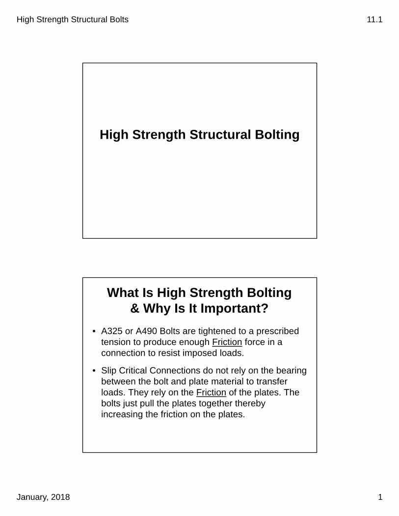
High Strength Structural Bolting
What Is High Strength Bolting & Why Is It Important?
• A325 or A490 Bolts are tightened to a prescribed tension to produce enough Friction force in a connection to resist imposed loads.
• Slip Critical Connections do not rely on the bearing between the bolt and plate material to transfer loads. They rely on the Friction of the plates. The bolts just pull the plates together thereby increasing the friction on the plates.
High Strength Structural Bolts 11.1
January, 2018 2
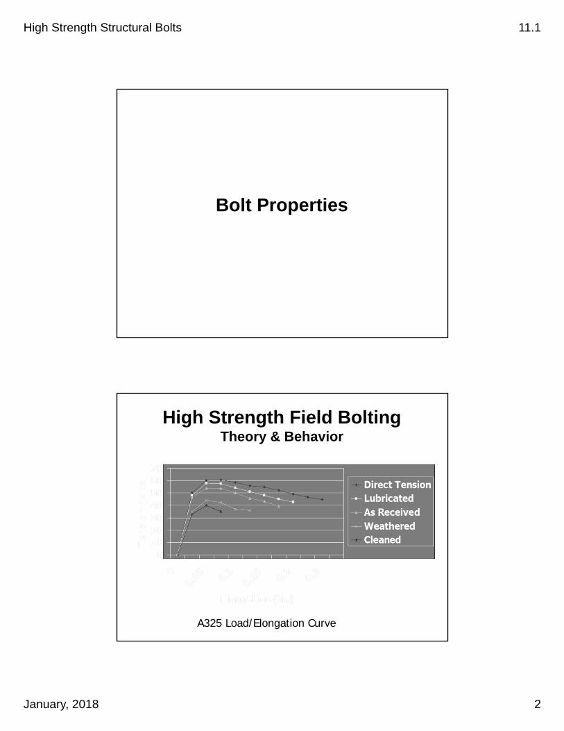
Bolt Properties
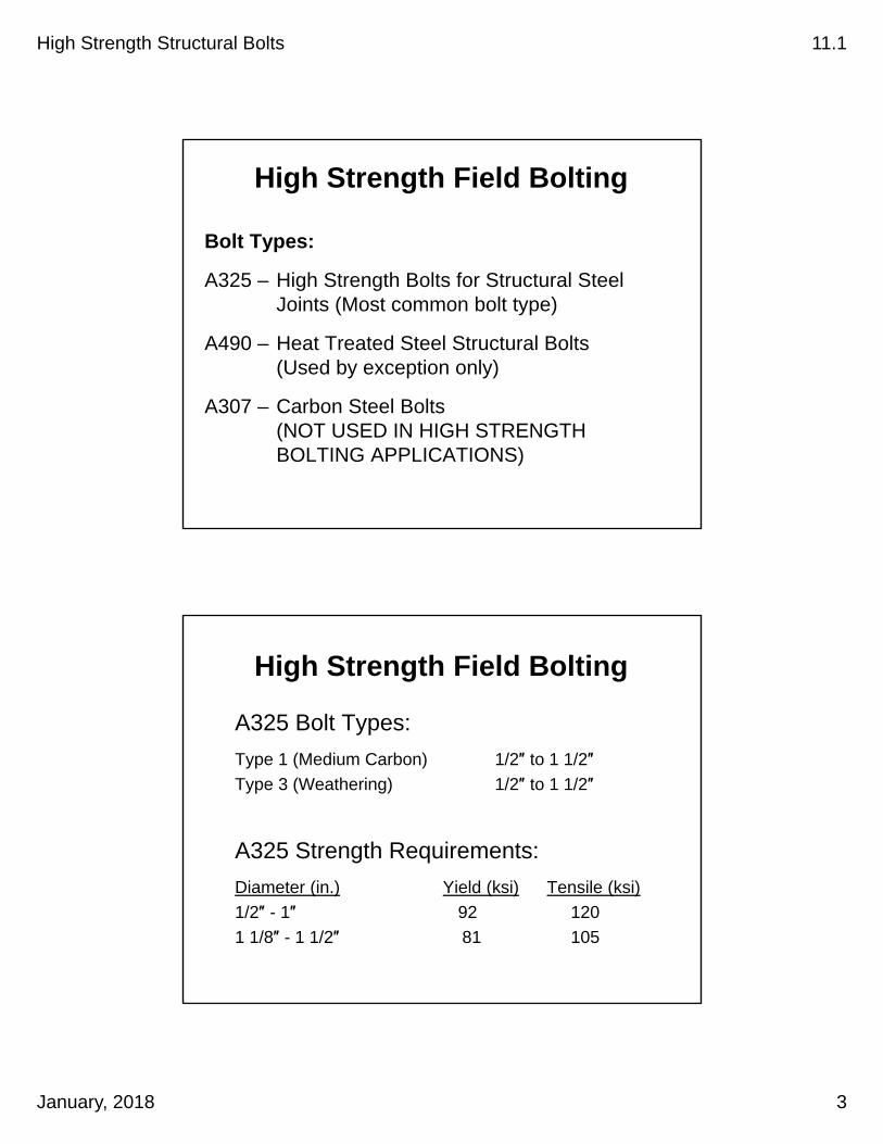
High Strength Field BoltingTheory & Behavior
A325 Load/Elongation Curve
High Strength Structural Bolts 11.1
January, 2018 3
High Strength Field Bolting
Bolt Types:
A325 – High Strength Bolts for Structural Steel Joints (Most common bolt type)
A490 – Heat Treated Steel Structural Bolts (Used by exception only)
A307 – Carbon Steel Bolts (NOT USED IN HIGH STRENGTH BOLTING APPLICATIONS)
High Strength Field Bolting
A325 Bolt Types:
Type 1 (Medium Carbon) 1/2″ to 1 1/2″
Type 3 (Weathering) 1/2″ to 1 1/2″
A325 Strength Requirements:
Diameter (in.) Yield (ksi) Tensile (ksi)
1/2″ - 1″ 92 120
1 1/8″ - 1 1/2″ 81 105

High Strength Structural Bolts 11.1
January, 2018 4
High Strength Field BoltingBolt Type Matching Nut
A325 A563 A194
Type 1 (Plain) C, D, DH 2, 2H
Type 1 (Galvanized) DH 2H
Type 3 (Weathering) C3, DH3
Note: All Nuts For High Strength Fasteners are Heavy Hex.
Non Heat Treated Nuts: Proof Load Stress = 150 ksi
Heat Treated Nuts: Proof Load Stress = 175 ksi
High Strength Field Bolting
Hardened Steel Washers:
• ASTM F436
• Type 1 – Carbon Steel (Plain or Galvanized)
• Type 3 – Weathering Steel
• Rockwell Hard. Values: 38 to 45 (Plain) - 170 ksi26 to 45 (Galvanized) - 125 ksi
High Strength Structural Bolts 11.1
January, 2018 5
Methods of Tightening
Methods of Tightening
• Turn of Nut Method
• Direct Tension Indicators (DTI’s)
• Tension Control Fasteners

High Strength Structural Bolts 11.1
January, 2018 6
Steel Girder Construction
• Most splice and connection bolts on our girders are installed using the Turn-of-Nut Method.
• DTI’s are not used.
• TC bolts are used some.
Field Tests
High Strength Structural Bolts 11.1
January, 2018 7
Field Tests At The Project Site
• Rotational Capacity Test
• Verification Test
• Inspection Torque
Rotational Capacity Test for Long Bolts

TUR
N-O
F-N
UT
MET
HO
D (L
ON
G B
OLT
S)
PRO
CES
SES
PUR
POSE
1. R
otat
iona
l Cap
acity
Tes
tC
heck
s bo
lts fo
r ove
rall
capa
city
, pro
per l
ubric
atio
n, a
nd fo
r dam
age
durin
g st
orag
e or
tran
sit
2. V
erifi
catio
n Te
st
Dem
onst
rate
s th
at C
ontra
ctor
's e
quip
men
t & p
roce
dure
will
tigh
ten
bolts
to p
rope
r ten
sion
3.
Ins
pect
ion
Torq
ueD
eter
min
es to
rque
val
ue to
be
used
in th
e ra
ndom
fiel
d in
spec
tion
4. R
ando
m F
ield
Insp
ectio
nC
heck
s bo
lt in
stal
latio
n on
stru
ctur
e us
ing
the
Job
Insp
ectio
n To
rque
PRO
CES
SES
PRO
CED
UR
E
1. R
otat
iona
l Cap
acity
Tes
t1.
Sam
ple
2 bo
lt, w
ashe
r & n
ut a
ssem
blie
s
(02
560.
60 (a
))2.
Ass
embl
e fa
sten
er w
ith 3
-5 th
read
s w
ithin
the
grip
3. S
nug
tight
(10%
of R
equi
red
Fast
ener
Ten
sion
in T
able
560
-1);
Tole
ranc
e= -0
kip
s, +
2 ki
ps4.
Mar
k th
e bo
lt, n
ut &
pla
te5.
Tig
hten
to R
equi
red
Fast
ener
Ten
sion
& re
cord
torq
ue (t
orqu
e m
ust n
ot e
xcee
d T=
0.25
PD
) (P
in lb
s, D
in ft
)6.
Tur
n nu
t to
twic
e th
e ro
tatio
n in
Tab
le 5
60-3
(ten
sion
mus
t exc
eed
115%
of R
equi
red
Fast
ener
Ten
sion
)7.
Rem
ove
nut a
nd c
heck
thre
ads
2. V
erifi
catio
n Te
st1.
Sam
ple
3 bo
lt, w
ashe
r & n
ut a
ssem
blie
s
(00
560.
29 (c
)(1
& 5
))2.
Snu
g tig
ht (P
lies
of jo
int i
n fir
m c
onta
ct, f
ull e
ffort
on 1
2" s
pud
wre
nch;
10%
of R
FT<
Tens
ion
< 50
% o
f RFT
)3.
Mar
k th
e bo
lt, n
ut &
pla
te4.
Tig
hten
nut
to th
e ro
tatio
n in
Tab
le 5
60-3
(max
. of 1
0 se
cond
s w
ith im
pact
wre
nch)
5. V
erify
tens
ion
is 5
% g
reat
er th
an R
equi
red
Fast
ener
Ten
sion
3. I
nspe
ctio
n To
rque
1. S
ampl
e 3
bolt,
was
her &
nut
ass
embl
ies
(
0056
0.29
(d))
2. P
lace
in S
kidm
ore
& ti
ghte
n to
Req
uire
d Fa
sten
er T
ensi
on in
Tab
le 5
60-1
3. M
easu
re to
rque
requ
ired
to tu
rn th
e nu
t 5 d
egre
es (1
" @ 1
2" ra
dius
)4.
Ave
rage
the
3 te
sts
to d
eter
min
e th
e In
spec
tion
Torq
ue
4. R
ando
m F
ield
Insp
ectio
n1.
Sel
ect a
t ran
dom
10%
of t
he te
nsio
ned
bolts
in e
ach
conn
ectio
n (2
min
imum
)
(00
560.
29 (d
))2.
App
ly In
spec
tion
Torq
ue.
If no
ne tu
rn, t
he c
onne
ctio
n pa
sses
.3.
If o
ne o
r mor
e fa
sten
ers
turn
, ins
pect
ion
torq
ue a
ll fa
sten
ers
in th
e co
nnec
tion.
4. R
e-te
nsio
n &
insp
ect a
ll fa
sten
ers
that
turn
ed w
hen
appl
ying
the
Insp
ectio
n To
rque
.
734-
2629
Sum
mar
y (3
-201
2) C
onst
ruct
ion
Form
s W
ebsi
te:
http
://w
ww
.ore
gon.
gov/
OD
OT/
Hw
y/C
onst
ruct
ion/
Con
stFo
rms1
.sht
ml
HIG
H S
TREN
GTH
BO
LTIN
G S
UM
MA
RY

TUR
N-O
F-N
UT
MET
HO
D (S
HO
RT
BO
LTS)
PRO
CES
SES
PUR
POSE
1. R
otat
iona
l Cap
acity
Tes
tC
heck
s bo
lts fo
r ove
rall
capa
city
, pro
per l
ubric
atio
n an
d fo
r dam
age
durin
g st
orag
e or
tran
sit
2. V
erifi
catio
n Te
st
Dem
onst
rate
s th
at C
ontra
ctor
's e
quip
men
t & p
roce
dure
will
tigh
ten
bolts
to p
rope
r ten
sion
3. I
nspe
ctio
n To
rque
Det
erm
ines
torq
ue v
alue
to b
e us
ed in
the
rand
om fi
eld
insp
ectio
n4.
Ran
dom
Fie
ld In
spec
tion
Che
cks
bolt
inst
alla
tion
on s
truct
ure
usin
g th
e In
spec
tion
Torq
ue
PRO
CES
SES
PRO
CED
UR
E
1. R
otat
iona
l Cap
acity
Tes
t1.
Sam
ple
2 bo
lt, w
ashe
r & n
ut a
ssem
blie
s
(02
560.
60 (a
))2.
Ass
embl
e fa
sten
er w
ith 3
-5 th
read
s w
ithin
the
grip
3. S
nug
tight
(10%
of m
ax a
llow
able
torq
ue <
Tor
que
< 20
% o
f MA
T, M
AT=
1.15
(0.2
5PD
)) (
P in
lbs,
D in
ft)
4. M
ark
sock
et5.
Tig
hten
nut
to ro
tatio
n in
Tab
le56
0-3
& re
cord
torq
ue (t
orqu
e m
ust n
ot e
xcee
d T=
1.15
(0.2
5PD
)6.
Tur
n nu
t to
twic
e th
e ro
tatio
n in
Tab
le 5
60-3
7. R
emov
e nu
t and
che
ck th
read
s
2. V
erifi
catio
n Te
st1.
Sam
ple
3 bo
lt, w
ashe
r & n
ut a
ssem
blie
s
(00
560.
29 (c
)(1
& 5
))2.
Snu
g tig
ht (J
oint
plie
s in
firm
con
tact
, ful
l effo
rt on
spu
d w
renc
h; 1
0% o
f MA
T< T
orqu
e <
50%
of M
AT
3. M
ark
the
bolt,
nut
& p
late
4. T
ight
en n
ut to
the
rota
tion
in T
able
560
-35.
Ver
ify to
rque
is 5
% g
reat
er th
an a
vera
ge o
f the
reco
rded
torq
ues
@ tu
rn re
quire
men
t in
the
RoC
ap T
est
3. I
nspe
ctio
n To
rque
1. S
ampl
e 3
bolt,
was
her &
nut
ass
embl
ies
(
0056
0.29
(d))
2. S
nug
tight
(10%
of m
ax a
llow
able
torq
ue <
Tor
que
< 20
% o
f MA
T, M
AT=
1.15
(0.2
5PD
)) (
P in
lbs,
D in
ft)
3. M
ark
the
bolt,
nut
& p
late
4. T
ight
en n
ut to
the
rota
tion
in T
able
560
-33.
Mea
sure
torq
ue re
quire
d to
turn
the
nut 5
deg
rees
(1" @
12"
radi
us)
4. A
vera
ge th
e 3
test
s to
det
erm
ine
the
Insp
ectio
n To
rque
4. R
ando
m F
ield
Insp
ectio
n1.
Sel
ect a
t ran
dom
10%
of t
he te
nsio
ned
bolts
in e
ach
conn
ectio
n (2
min
imum
)
(00
560.
29 (d
))2.
App
ly J
ob In
spec
tion
Torq
ue.
If no
ne tu
rn, t
he c
onne
ctio
n pa
sses
.3.
If o
ne o
r mor
e fa
sten
ers
turn
, ins
pect
ion
torq
ue a
ll fa
sten
ers
in th
e co
nnec
tion.
4. R
e-te
nsio
n &
insp
ect a
ll fa
sten
ers
that
turn
ed w
hen
appl
ying
the
Insp
ectio
n To
rque
.
734-
2630
Sum
mar
y (3
-201
2) C
onst
ruct
ion
Form
s W
ebsi
te:
http
://w
ww
.ore
gon.
gov/
OD
OT/
Hw
y/C
onst
ruct
ion/
Con
stFo
rms1
.sht
ml
HIG
H S
TREN
GTH
BO
LTIN
G S
UM
MA
RY
High Strength Structural Bolts 11.1
January, 2018 8
View Rotational Capacity Test for Long Bolts
Rotational-Capacity Test Equipment
Skidmore-Wilhelm or Equivalent
• Calibrated Yearly
Standard Torque Wrench
• 1000 ft. lb. Capacity
• Calibrated Yearly
Rigid Steel Joint
• Short Bolt Fasteners

Project Contract No.
Company Test No.
RCT-Torque Wrench Serial No. Calibration Due Date
Skidmore Serial No. Calibration Due Date
Bolt Diameter Bolt Length Quantity
Bolt Mfg. Lot No. Heat No.
Nut Mfg. Lot No. Heat No.
Washer Mfg. Lot No. Heat No.
Ro-Cap Sample 1: Required Fastener Tension = Lbs. (Table 00560-1)Snug Tight Tension = Lbs. (0.10 x Req. Fastener Tension): Tol. = -0 kips + 2 kipsMeasured Torque = Maximum Allowable Torque = Ft.-Lbs. (T < 0.25PD); (P in Lbs., D in Ft.)Measured Tension = Lbs. @ Turn (2x Rotation In Table 00560-3)Minimum Tension Required = Lbs. (1.15 X Required Fastener Tension)
Sample 1 Results:Ro-Cap Sample 2: Required Fastener Tension = Lbs. (Table 00560-1)Snug Tight Tension = Lbs. (0.10 x Req. Fastener Tension): Tol. = -0 kips + 2 kipsMeasured Torque = Maximum Allowable Torque = Ft.-Lbs. (T < 0.25PD); (P in Lbs., D in Ft.)Measured Tension = Lbs. @ Turn (2x Rotation In Table 00560-3)Minimum Tension Required = Lbs. (1.15 X Required Fastener Tension)
Sample 2 Results:
Rotational Capacity Test Results:Inspection Torque Sample 1:Required Fastener Tension = Lbs. (Table 00560-1)Measured Torque = Ft.-Lbs. @ Additional 5 Degrees (Apprx. 1" @ 12" Radius)
Inspection Torque Sample 2:Required Fastener Tension = Lbs. (Table 00560-1)Measured Torque = Ft.-Lbs. @ Additional 5 Degrees (Apprx. 1" @ 12" Radius)
Inspection Torque Sample 3:Required Fastener Tension = Lbs. (Table 00560-1)Measured Torque = Ft.-Lbs. @ Additional 5 Degrees (Apprx. 1" @ 12" Radius)
Inspection Torque = Ft.-Lbs. (Average of the 3 Inspection Torque Samples)
Comments:
Inspector Cert No. Title
Contractor's Representative Date
734-2629 (3-2012) Construction Forms Website: http://www.oregon.gov/ODOT/Hwy/Construction/ConstForms1.shtml
Ft.-Lbs. @ Required Fastener Tension (Go to Insp. Torque)
Ft.-Lbs. @ Required Fastener Tension (Go to Insp. Torque)
32200
280003000
28000
HIGH STRENGTH BOLTS ROTATIONAL CAPACITY TEST & INSPECTION TORQUE
(LONG BOLTS)
3000
438
438
32200
28000
#DIV/0!
28000
28000
Pass Fail
Accept Reject
Pass Fail
3/4 inch
Turn of Nut MethodTurn of Nut Method Direct Tension IndicatorDirect Tension Indicator Tension Control FastenerTension Control Fastener

High Strength Structural Bolts 11.1
January, 2018 9
Table 560-1
A325 Bolts
Note: A490 Bolts require higher tensions
Table 560-3

High Strength Structural Bolts 11.1
January, 2018 10
Ro-Cap Test for Long Bolts
1. Sample 2 Bolt/Washer/Nut Assemblies
2. Assemble fastener with 3-5 threads within grip
3. Snug tight (10% of req’d fast. tension, Table 560-1)
(Tolerance= -0 kips to +2 kips)
4. Mark socket
5. Tighten to req’d fast. tension and record torque (torque must not exceed T=0.25PD) (P in lbs, D in ft)
6. Turn nut to twice the rotation in Table 560-3 (tension must exceed 115% of req’d fast. tension)
Skidmore/Wilhelm
High Strength Structural Bolts 11.1
January, 2018 11
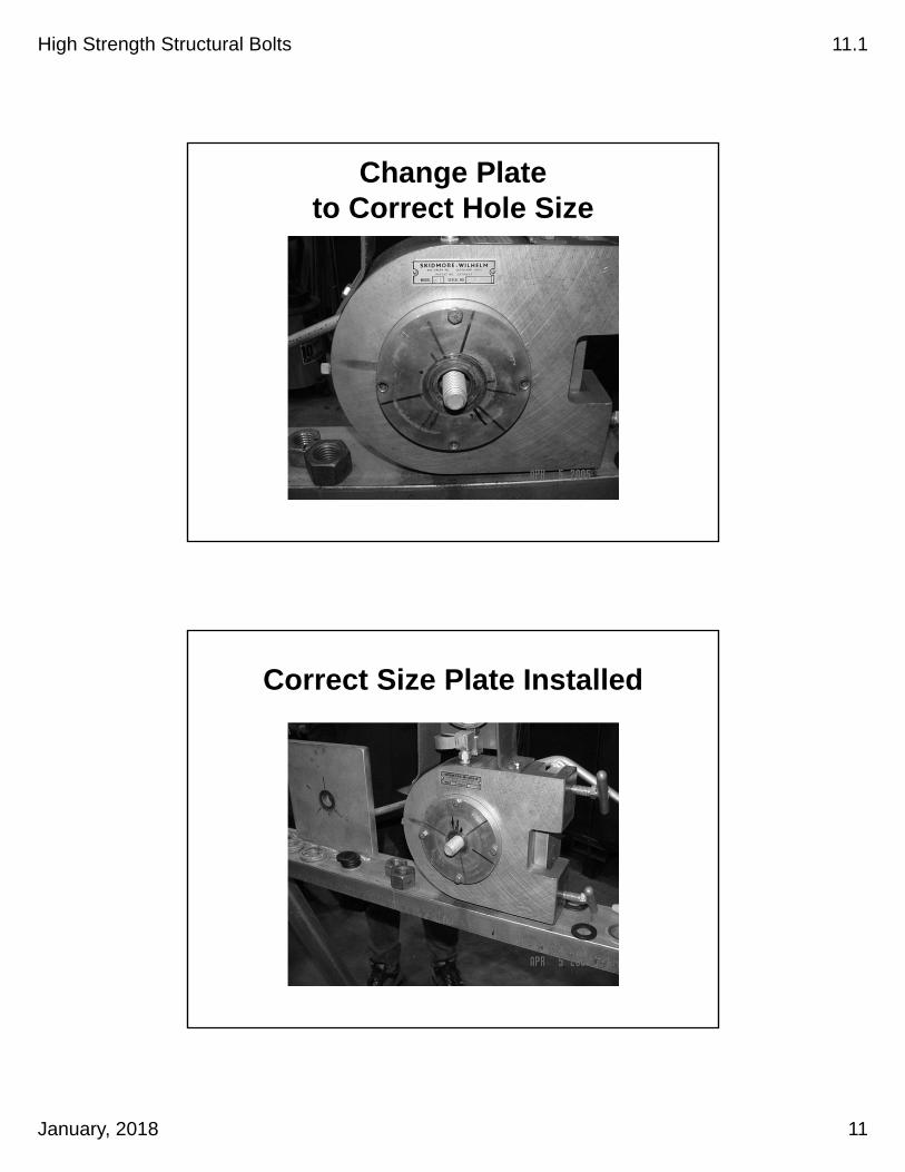
Change Plate to Correct Hole Size
Correct Size Plate Installed

High Strength Structural Bolts 11.1
January, 2018 12
Bolt Head Insert On Backside
3 to 5 threads in grip
washers orshims
one washer minimum
3 - 5 Threads in Grip

High Strength Structural Bolts 11.1
January, 2018 13
3-5 Threads in Grip
Added Washers to Maintain 3-5 Threads Within Grip
High Strength Structural Bolts 11.1
January, 2018 14
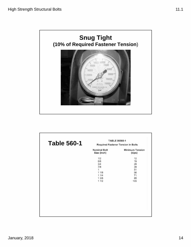
Snug Tight (10% of Required Fastener Tension)
Table 560-1
High Strength Structural Bolts 11.1
January, 2018 15
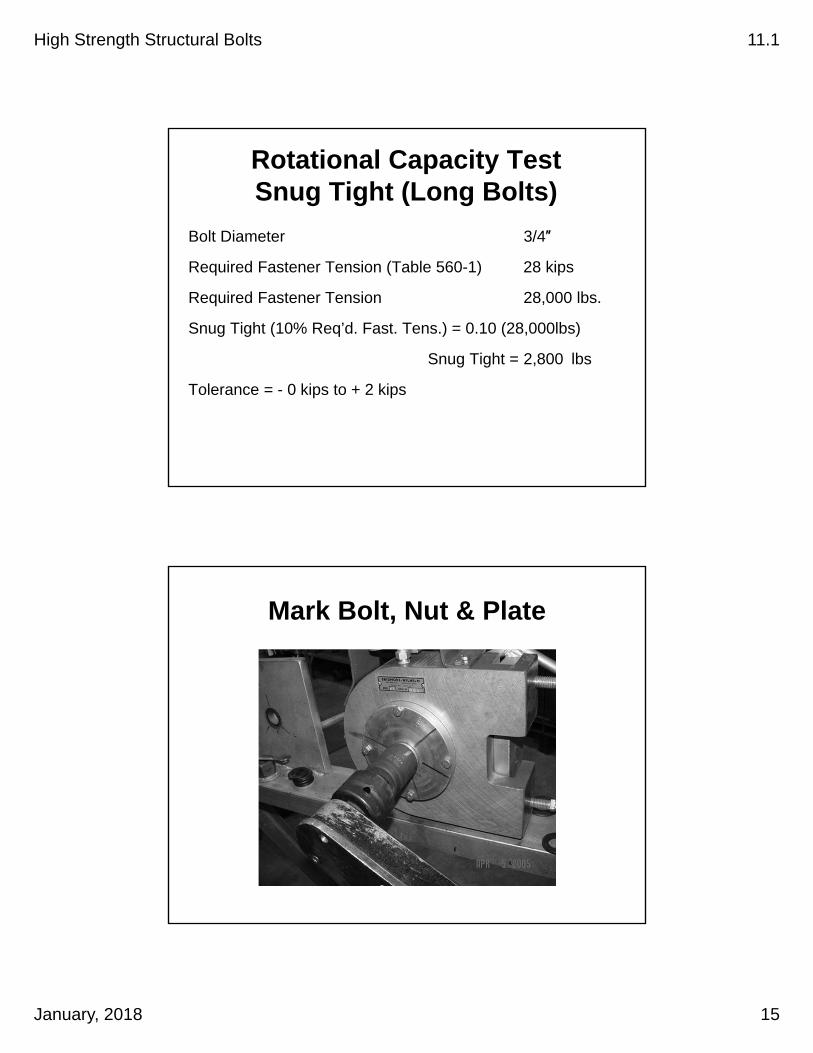
Rotational Capacity TestSnug Tight (Long Bolts)
Bolt Diameter 3/4″
Required Fastener Tension (Table 560-1) 28 kips
Required Fastener Tension 28,000 lbs.
Snug Tight (10% Req’d. Fast. Tens.) = 0.10 (28,000lbs)
Snug Tight = 2,800 lbs
Tolerance = - 0 kips to + 2 kips
Mark Bolt, Nut & Plate

High Strength Structural Bolts 11.1
January, 2018 16
Mark Bolt, Nut & Plate
Tighten to Req’d Fastener Tension

High Strength Structural Bolts 11.1
January, 2018 17
Record Torque
Rotational Capacity TestMaximum Torque, T=0.25 PD
Diameter 3/4″
Required Fastener Tension 28 kips(Table 560-1)
Max. Torque, T = 0.25 PD(P in lbs, D in ft)
Max. Torque, T = 0.25(28,000 lbs)(3/4″)(1 ft/12″) = 438 ft-lbs
Max. Torque, T = 438 ft-lbs

High Strength Structural Bolts 11.1
January, 2018 18
Turn Nut
Twice Rotation Specified in Table 560-3
Turn Nut to Twice the Rotation
Table 560-3
High Strength Structural Bolts 11.1
January, 2018 19
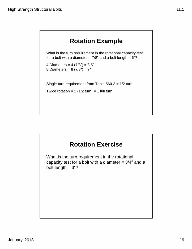
Rotation Example
What is the turn requirement in the rotational capacity test for a bolt with a diameter = 7/8″ and a bolt length = 6″?
4 Diameters = 4 (7/8″) = 3.5″8 Diameters = 8 (7/8″) = 7″
Single turn requirement from Table 560-3 = 1/2 turn
Twice rotation = 2 (1/2 turn) = 1 full turn
Rotation Exercise
What is the turn requirement in the rotational capacity test for a bolt with a diameter = 3/4″ and a bolt length = 3″?
High Strength Structural Bolts 11.1
January, 2018 20
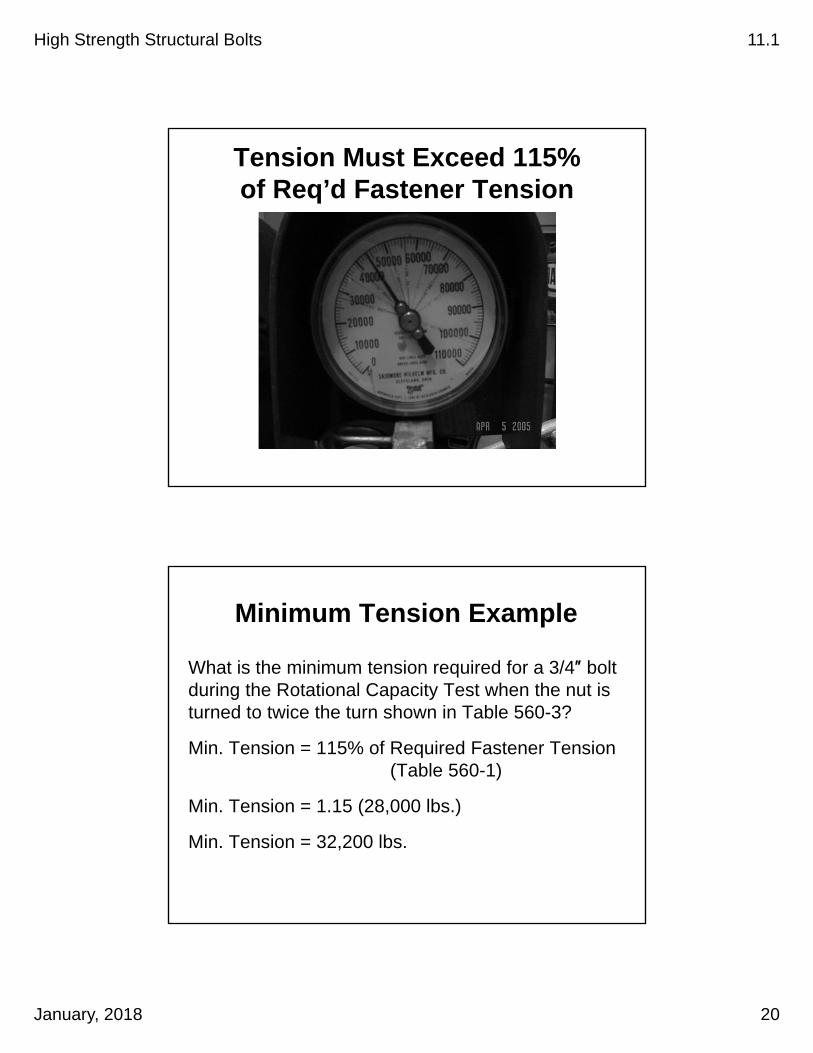
Tension Must Exceed 115% of Req’d Fastener Tension
Minimum Tension Example
What is the minimum tension required for a 3/4″ bolt during the Rotational Capacity Test when the nut is turned to twice the turn shown in Table 560-3?
Min. Tension = 115% of Required Fastener Tension (Table 560-1)
Min. Tension = 1.15 (28,000 lbs.)
Min. Tension = 32,200 lbs.

High Strength Structural Bolts 11.1
January, 2018 21
Examine Bolt and Nut
Reject assemblies showing thread stripping or torsional failure. Elongation of the threads in the grip is normal.
Rotational Capacity Test for Short Bolts

High Strength Structural Bolts 11.1
January, 2018 22
View Short Bolt Video
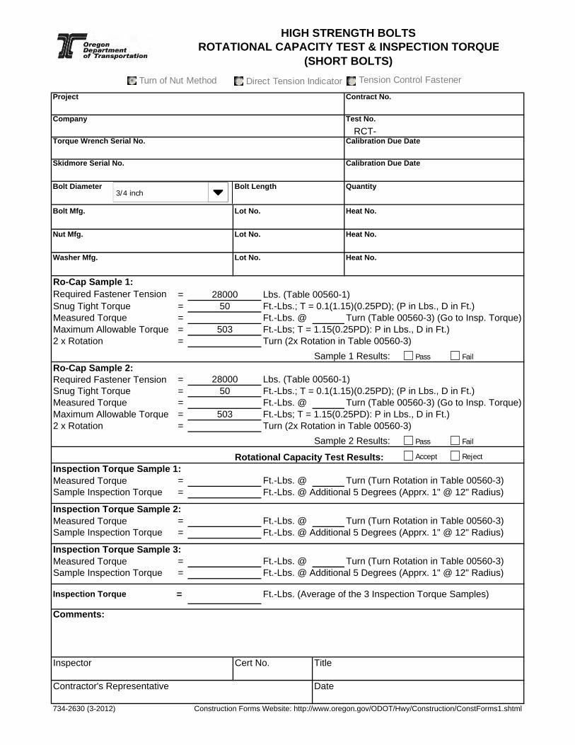
Ro-Cap Test for Short Bolts
1. Sample 2 Bolt/Washer/Nut Assemblies
2. Assemble fastener with 3-5 threads within grip
3. Snug tight (10% of max allowable torque < Torque < 20% of MAT, MAT=1.15(0.25PD)) (P in lbs, D in ft)
4. Mark nut (socket) relative to fixed bolt
5. Tighten nut to rotation in Table 560-3 and record torque (torque must not exceed 1.15 allowed torque)
6. Turn nut to twice the rotation in Table 560-3
Project Contract No.
Company Test No.
Torque Wrench Serial No. Calibration Due Date
Skidmore Serial No. Calibration Due Date
Bolt Diameter Bolt Length Quantity
Bolt Mfg. Lot No. Heat No.
Nut Mfg. Lot No. Heat No.
Washer Mfg. Lot No. Heat No.
Ro-Cap Sample 1: Required Fastener Tension = Lbs. (Table 00560-1)Snug Tight Torque = Ft.-Lbs.; T = 0.1(1.15)(0.25PD); (P in Lbs., D in Ft.)Measured Torque = Ft.-Lbs. @ Maximum Allowable Torque = Ft.-Lbs; T = 1.15(0.25PD): P in Lbs., D in Ft.)2 x Rotation = Turn (2x Rotation in Table 00560-3)
Sample 1 Results:Ro-Cap Sample 2: Required Fastener Tension = Lbs. (Table 00560-1)Snug Tight Torque = Ft.-Lbs.; T = 0.1(1.15)(0.25PD); (P in Lbs., D in Ft.)Measured Torque = Ft.-Lbs. @ Maximum Allowable Torque = Ft.-Lbs; T = 1.15(0.25PD): P in Lbs., D in Ft.)2 x Rotation = Turn (2x Rotation in Table 00560-3)
Sample 2 Results:
Rotational Capacity Test Results:Inspection Torque Sample 1:Measured Torque = Ft.-Lbs. @ Turn (Turn Rotation in Table 00560-3)Sample Inspection Torque = Ft.-Lbs. @ Additional 5 Degrees (Apprx. 1" @ 12" Radius)
Inspection Torque Sample 2:Measured Torque = Ft.-Lbs. @ Turn (Turn Rotation in Table 00560-3)Sample Inspection Torque = Ft.-Lbs. @ Additional 5 Degrees (Apprx. 1" @ 12" Radius)
Inspection Torque Sample 3:Measured Torque = Ft.-Lbs. @ Turn (Turn Rotation in Table 00560-3)Sample Inspection Torque = Ft.-Lbs. @ Additional 5 Degrees (Apprx. 1" @ 12" Radius)
Inspection Torque = Ft.-Lbs. (Average of the 3 Inspection Torque Samples)
Comments:
Inspector Cert No. Title
Contractor's Representative Date
734-2630 (3-2012) Construction Forms Website: http://www.oregon.gov/ODOT/Hwy/Construction/ConstForms1.shtml
Turn (Table 00560-3) (Go to Insp. Torque)
Turn (Table 00560-3) (Go to Insp. Torque)
#DIV/0!
50
503
503
5028000
HIGH STRENGTH BOLTS ROTATIONAL CAPACITY TEST & INSPECTION TORQUE
(SHORT BOLTS)
RCT-
28000
Pass Fail
Accept Reject
Pass Fail
3/4 inch
Turn of Nut MethodTurn of Nut Method Direct Tension IndicatorDirect Tension Indicator Tension Control FastenerTension Control Fastener

High Strength Structural Bolts 11.1
January, 2018 23
Short Bolt Method
Verification Testing
Turn-of-Nut Method

Project Contract No.
Company Test No.
Torque Wrench Serial No. Calibration Due Date
Skidmore Serial No. Calibration Due Date
Bolt Diameter Bolt Length Quantity
Bolt Mfg. Lot No. Heat No.
Nut Mfg. Lot No. Heat No.
Washer Mfg. Lot No. Heat No.
Verification Sample 1: Required Fastener Tension = Lbs. (Table 00560-1)Meas'd Tension @ Snug Tight = Lbs.(Joint Plies in Firm Contact, Full Effort on Spud Wrench)
(10% Req'd Fastener Tension < Snug Tight < 50% RFT)Measured Time = Seconds (From Snug Tight to Turn Rotation in Table 00560-3)Maximum Allowable Time = Seconds (From Snug Tight to Turn Rotation in Table 00560-3)Measured Tension = Lbs. @ Turn (Turn Rotation In Table 00560-3)Minimum Tension Required = Lbs. (1.05 X Required Fastener Tension)
Sample 1 Results:Verification Sample 2: Required Fastener Tension = Lbs. (Table 00560-1)Meas'd Tension @ Snug Tight = Lbs.(Joint Plies in Firm Contact, Full Effort on Spud Wrench)
(10% Req'd Fastener Tension < Snug Tight < 50% RFT)Measured Time = Seconds (From Snug Tight to Turn Rotation in Table 00560-3)Maximum Allowable Time = Seconds (From Snug Tight to Turn Rotation in Table 00560-3)Measured Tension = Lbs. @ Turn (Turn Rotation In Table 00560-3)Minimum Tension Required = Lbs. (1.05 X Required Fastener Tension)
Sample 2 Results:Verification Sample 3: Required Fastener Tension = Lbs. (Table 00560-1)Meas'd Tension @ Snug Tight = Lbs.(Joint Plies in Firm Contact, Full Effort on Spud Wrench)
(10% Req'd Fastener Tension < Snug Tight < 50% RFT)Measured Time = Seconds (From Snug Tight to Turn Rotation in Table 00560-3)Maximum Allowable Time = Seconds (From Snug Tight to Turn Rotation in Table 00560-3)Measured Tension = Lbs. @ Turn (Turn Rotation In Table 00560-3)Minimum Tension Required = Lbs. (1.05 X Required Fastener Tension)
Sample 2 Results:Verification Test Results:Comments:
Inspector Cert No. Title
Contractor's Representative Date
734-2747 (3-2012) Construction Forms Website: http://www.oregon.gov/ODOT/Hwy/Construction/ConstForms1.shtml
28000
10
10
29400
28000
29400
28000
VT-
HIGH STRENGTH BOLTS VERIFICATION TEST (LONG BOLTS)
29400
10
3/4 inch
Turn of Nut MethodTurn of Nut Method Direct Tension IndicatorDirect Tension Indicator Tension Control FastenerTension Control Fastener
Pass Fail
Accept Reject
Pass Fail
FailPass

High Strength Structural Bolts 11.1
January, 2018 24
Verification Testing for Long Bolts Turn-of-Nut Method
1. Sample 3 Bolt/Washer/Nut Assembles
2. Snug the bolt using method to be used on the structure
(plies of joint in firm contact; full effort on 12″ spud wrench)
(10% of RFT < Tension < 50% of RFT)
3. Mark the Bolt/Nut/Plate
4. Tighten nut to rotation in Table 560-3
5. Verify tension is 5% greater than proof load
Turn-of-Nut Verification TestingLong Bolt Example
Diameter = ¾″
Length = 3″
Required Rotation (Turns) = 1/3
Required Fastener Tension = 28,000 lbs
Req’d Verification Tension = (105%) Req’d Fast Tension
Req’d Verification Tension = (1.05)(28,000) = 29,400 lbs.
High Strength Structural Bolts 11.1
January, 2018 25
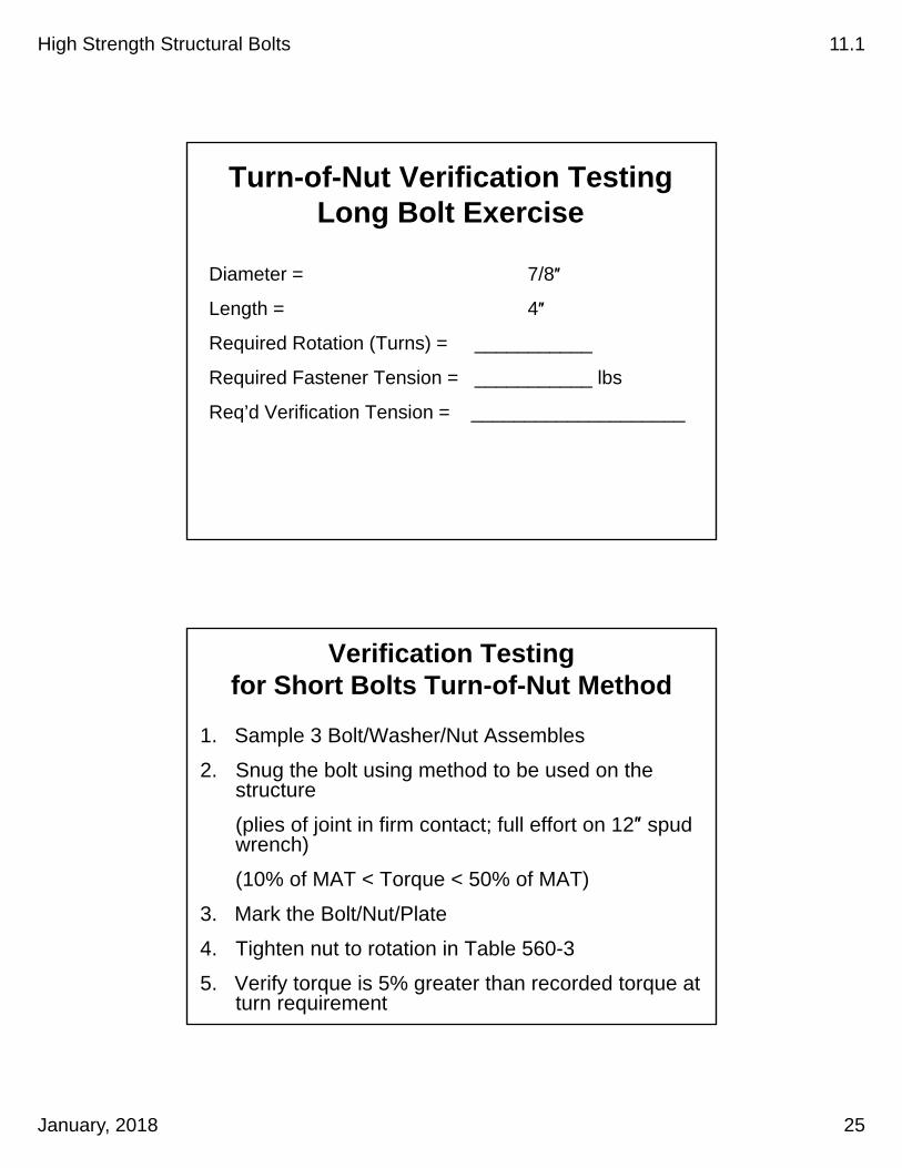
Turn-of-Nut Verification TestingLong Bolt Exercise
Diameter = 7/8″
Length = 4″
Required Rotation (Turns) = ___________
Required Fastener Tension = ___________ lbs
Req’d Verification Tension = ____________________
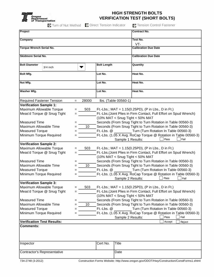
Verification Testing for Short Bolts Turn-of-Nut Method
1. Sample 3 Bolt/Washer/Nut Assembles
2. Snug the bolt using method to be used on the structure
(plies of joint in firm contact; full effort on 12″ spud wrench)
(10% of MAT < Torque < 50% of MAT)
3. Mark the Bolt/Nut/Plate
4. Tighten nut to rotation in Table 560-3
5. Verify torque is 5% greater than recorded torque at turn requirement
Project Contract No.
Company Test No.
Torque Wrench Serial No. Calibration Due Date
Skidmore Serial No. Calibration Due Date
Bolt Diameter Bolt Length Quantity
Bolt Mfg. Lot No. Heat No.
Nut Mfg. Lot No. Heat No.
Washer Mfg. Lot No. Heat No.
Required Fastener Tension = lbs. (Table 00560-1)Verification Sample 1: Maximum Allowable Torque = Ft.-Lbs.; MAT = 1.15(0.25PD), (P in Lbs., D in Ft.)Meas'd Torque @ Snug Tight = Ft.-Lbs.(Joint Plies in Firm Contact, Full Effort on Spud Wrench)
(10% MAT < Snug Tight < 50% MATMeasured Time = Seconds (From Snug Tight to Turn Rotation in Table 00560-3)Maximum Allowable Time = Seconds (From Snug Tight to Turn Rotation in Table 00560-3)Measured Torque = Ft.-Lbs. @ Turn (Turn Rotation In Table 00560-3)Minimum Torque Required = Ft.-Lbs. (1.05 X Avg. RoCap Torque @ Rotation in Table 00560-3)
Sample 1 Results:Verification Sample 2: Maximum Allowable Torque = Ft.-Lbs.; MAT = 1.15(0.25PD), (P in Lbs., D in Ft.)Meas'd Torque @ Snug Tight = Ft.-Lbs.(Joint Plies in Firm Contact, Full Effort on Spud Wrench)
(10% MAT < Snug Tight < 50% MATMeasured Time = Seconds (From Snug Tight to Turn Rotation in Table 00560-3)Maximum Allowable Time = Seconds (From Snug Tight to Turn Rotation in Table 00560-3)Measured Torque = Ft.-Lbs. @ Turn (Turn Rotation In Table 00560-3)Minimum Torque Required = Ft.-Lbs. (1.05 X Avg. RoCap Torque @ Rotation in Table 00560-3)
Sample 2 Results:Verification Sample 3: Maximum Allowable Torque = Ft.-Lbs.; MAT = 1.15(0.25PD), (P in Lbs., D in Ft.)Meas'd Torque @ Snug Tight = Ft.-Lbs.(Joint Plies in Firm Contact, Full Effort on Spud Wrench)
(10% MAT < Snug Tight < 50% MATMeasured Time = Seconds (From Snug Tight to Turn Rotation in Table 00560-3)Maximum Allowable Time = Seconds (From Snug Tight to Turn Rotation in Table 00560-3)Measured Torque = Ft.-Lbs. @ Turn (Turn Rotation In Table 00560-3)Minimum Torque Required = Ft.-Lbs. (1.05 X Avg. RoCap Torque @ Rotation in Table 00560-3)
Sample 2 Results:Verification Test Results:Comments:
Inspector Cert No. Title
Contractor's Representative Date
734-2748 (3-2012) Construction Forms Website: http://www.oregon.gov/ODOT/Hwy/Construction/ConstForms1.shtml
10
VT-
503
503
28000
503
HIGH STRENGTH BOLTS VERIFICATION TEST (SHORT BOLTS)
10
10
3/4 inch
Turn of Nut MethodTurn of Nut Method Direct Tension IndicatorDirect Tension Indicator Tension Control FastenerTension Control Fastener
Pass Fail
Accept Reject
Pass Fail
FailPass
High Strength Structural Bolts 11.1
January, 2018 26
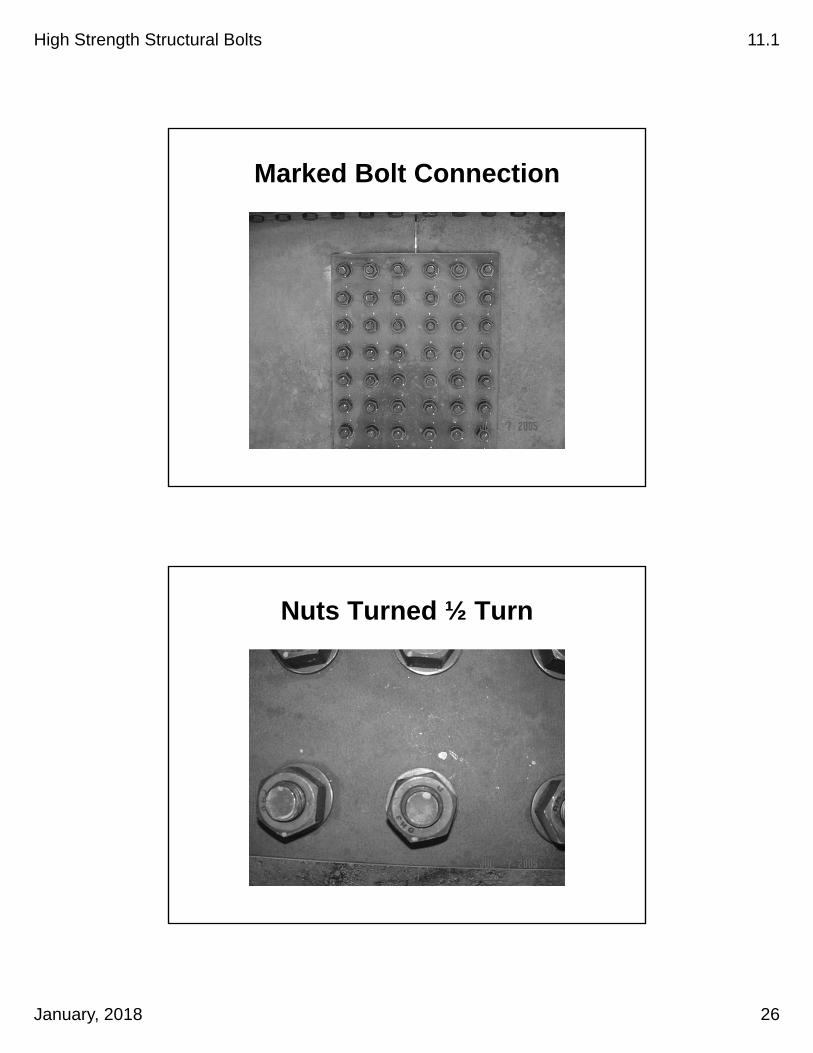
Marked Bolt Connection
Nuts Turned ½ Turn

High Strength Structural Bolts 11.1
January, 2018 27
Inspection Torque
Turn-of-Nut Method
Inspection Torque for Long Bolt Method (Turn of Nut)
1. Sample 3 Bolt/Washer/Nut assembles
2. Place in skidmore and tighten to required tension in Table 560-1
3. Measure torque required to turn the nut 5 degrees (1″ @ 12″ radius)
4. Inspection torque is the average of the 3 tests

Project Contract No.
Company Test No.
RCT-Torque Wrench Serial No. Calibration Due Date
Skidmore Serial No. Calibration Due Date
Bolt Diameter Bolt Length Quantity
Bolt Mfg. Lot No. Heat No.
Nut Mfg. Lot No. Heat No.
Washer Mfg. Lot No. Heat No.
Ro-Cap Sample 1: Required Fastener Tension = Lbs. (Table 00560-1)Snug Tight Tension = Lbs. (0.10 x Req. Fastener Tension): Tol. = -0 kips + 2 kipsMeasured Torque = Maximum Allowable Torque = Ft.-Lbs. (T < 0.25PD); (P in Lbs., D in Ft.)Measured Tension = Lbs. @ Turn (2x Rotation In Table 00560-3)Minimum Tension Required = Lbs. (1.15 X Required Fastener Tension)
Sample 1 Results:Ro-Cap Sample 2: Required Fastener Tension = Lbs. (Table 00560-1)Snug Tight Tension = Lbs. (0.10 x Req. Fastener Tension): Tol. = -0 kips + 2 kipsMeasured Torque = Maximum Allowable Torque = Ft.-Lbs. (T < 0.25PD); (P in Lbs., D in Ft.)Measured Tension = Lbs. @ Turn (2x Rotation In Table 00560-3)Minimum Tension Required = Lbs. (1.15 X Required Fastener Tension)
Sample 2 Results:
Rotational Capacity Test Results:Inspection Torque Sample 1:Required Fastener Tension = Lbs. (Table 00560-1)Measured Torque = Ft.-Lbs. @ Additional 5 Degrees (Apprx. 1" @ 12" Radius)
Inspection Torque Sample 2:Required Fastener Tension = Lbs. (Table 00560-1)Measured Torque = Ft.-Lbs. @ Additional 5 Degrees (Apprx. 1" @ 12" Radius)
Inspection Torque Sample 3:Required Fastener Tension = Lbs. (Table 00560-1)Measured Torque = Ft.-Lbs. @ Additional 5 Degrees (Apprx. 1" @ 12" Radius)
Inspection Torque = Ft.-Lbs. (Average of the 3 Inspection Torque Samples)
Comments:
Inspector Cert No. Title
Contractor's Representative Date
734-2629 (3-2012) Construction Forms Website: http://www.oregon.gov/ODOT/Hwy/Construction/ConstForms1.shtml
Ft.-Lbs. @ Required Fastener Tension (Go to Insp. Torque)
Ft.-Lbs. @ Required Fastener Tension (Go to Insp. Torque)
32200
280003000
28000
HIGH STRENGTH BOLTS ROTATIONAL CAPACITY TEST & INSPECTION TORQUE
(LONG BOLTS)
3000
438
438
32200
28000
#DIV/0!
28000
28000
Pass Fail
Accept Reject
Pass Fail
3/4 inch
Turn of Nut MethodTurn of Nut Method Direct Tension IndicatorDirect Tension Indicator Tension Control FastenerTension Control Fastener

Project Contract No.
Company Test No.
Torque Wrench Serial No. Calibration Due Date
Skidmore Serial No. Calibration Due Date
Bolt Diameter Bolt Length Quantity
Bolt Mfg. Lot No. Heat No.
Nut Mfg. Lot No. Heat No.
Washer Mfg. Lot No. Heat No.
Ro-Cap Sample 1: Required Fastener Tension = Lbs. (Table 00560-1)Snug Tight Torque = Ft.-Lbs.; T = 0.1(1.15)(0.25PD); (P in Lbs., D in Ft.)Measured Torque = Ft.-Lbs. @ Maximum Allowable Torque = Ft.-Lbs; T = 1.15(0.25PD): P in Lbs., D in Ft.)2 x Rotation = Turn (2x Rotation in Table 00560-3)
Sample 1 Results:Ro-Cap Sample 2: Required Fastener Tension = Lbs. (Table 00560-1)Snug Tight Torque = Ft.-Lbs.; T = 0.1(1.15)(0.25PD); (P in Lbs., D in Ft.)Measured Torque = Ft.-Lbs. @ Maximum Allowable Torque = Ft.-Lbs; T = 1.15(0.25PD): P in Lbs., D in Ft.)2 x Rotation = Turn (2x Rotation in Table 00560-3)
Sample 2 Results:
Rotational Capacity Test Results:Inspection Torque Sample 1:Measured Torque = Ft.-Lbs. @ Turn (Turn Rotation in Table 00560-3)Sample Inspection Torque = Ft.-Lbs. @ Additional 5 Degrees (Apprx. 1" @ 12" Radius)
Inspection Torque Sample 2:Measured Torque = Ft.-Lbs. @ Turn (Turn Rotation in Table 00560-3)Sample Inspection Torque = Ft.-Lbs. @ Additional 5 Degrees (Apprx. 1" @ 12" Radius)
Inspection Torque Sample 3:Measured Torque = Ft.-Lbs. @ Turn (Turn Rotation in Table 00560-3)Sample Inspection Torque = Ft.-Lbs. @ Additional 5 Degrees (Apprx. 1" @ 12" Radius)
Inspection Torque = Ft.-Lbs. (Average of the 3 Inspection Torque Samples)
Comments:
Inspector Cert No. Title
Contractor's Representative Date
734-2630 (3-2012) Construction Forms Website: http://www.oregon.gov/ODOT/Hwy/Construction/ConstForms1.shtml
Turn (Table 00560-3) (Go to Insp. Torque)
Turn (Table 00560-3) (Go to Insp. Torque)
#DIV/0!
50
503
503
5028000
HIGH STRENGTH BOLTS ROTATIONAL CAPACITY TEST & INSPECTION TORQUE
(SHORT BOLTS)
RCT-
28000
Pass Fail
Accept Reject
Pass Fail
3/4 inch
Turn of Nut MethodTurn of Nut Method Direct Tension IndicatorDirect Tension Indicator Tension Control FastenerTension Control Fastener

High Strength Structural Bolts 11.1
January, 2018 28
Inspection Torque for Short Bolt Method (Turn of Nut)
1. Sample 3 Bolt/Washer/Nut assembles
2. Snug tight (10% of MAT< Torque < 20% of MAT)
Maximum Allowable Torque = 1.15(0.25)PD)
3. Mark the Bolt/Nut/Plate
4. Tighten nut to rotation in Table 560-3
5. Measure torque required to turn the nut 5 degrees (1″ @ 12″ radius)
6. Inspection torque is the average of the 3 tests
Field Inspection
Turn-of-Nut Method

High Strength Structural Bolts 11.1
January, 2018 29
Field Inspection(Turn of Nut Method)
– Select at random 10% of the tensioned bolts (2 minimum) in each connection.
– Apply Inspection Torque. If none turn, the connection passes.
– If one or more fasteners turn, job torque the remaining fasteners in the connection.
– Re-tension and inspect all fasteners that turned for minimum Inspection Torque.
Field Inspection Cont’d
• Nut Turned to Rotation in Table 560-3
• +/- 30° for 1/3 & 1/2 turns
High Strength Structural Bolts 11.1
January, 2018 30
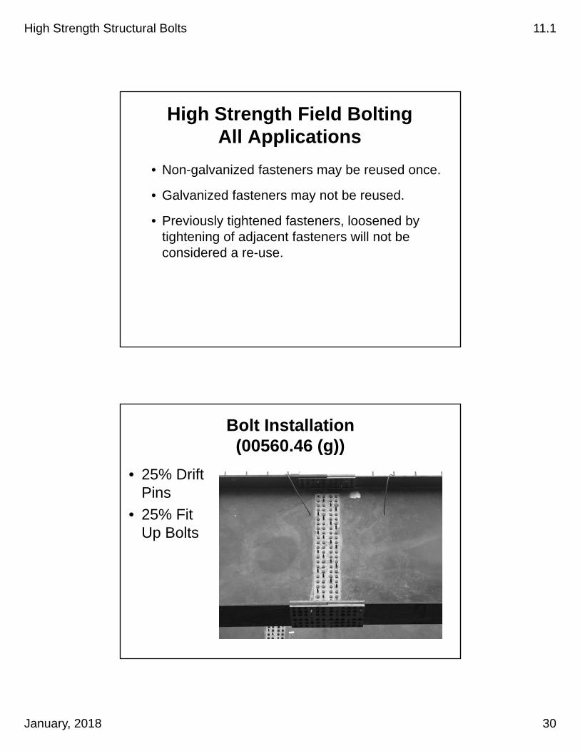
High Strength Field BoltingAll Applications
• Non-galvanized fasteners may be reused once.
• Galvanized fasteners may not be reused.
• Previously tightened fasteners, loosened by tightening of adjacent fasteners will not be considered a re-use.
Bolt Installation(00560.46 (g))
• 25% Drift Pins
• 25% Fit Up Bolts
High Strength Structural Bolts 11.1
January, 2018 31
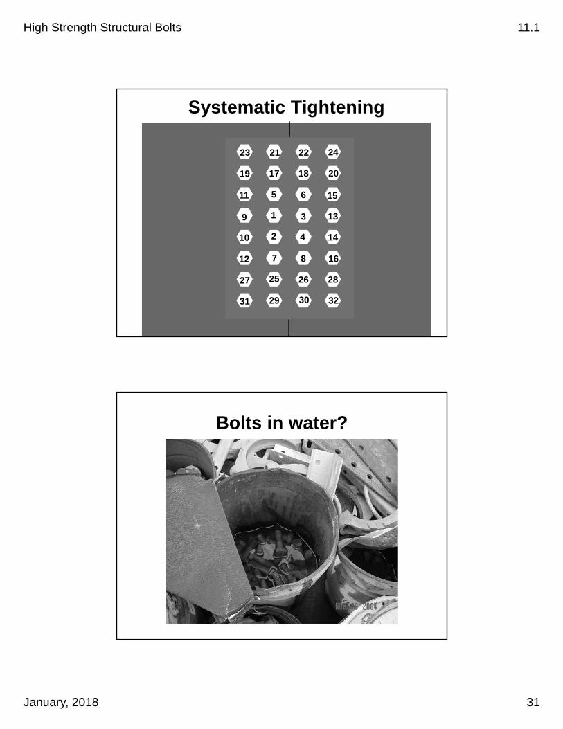
Systematic Tightening
1
2 4
3
5
8
6
7
26
30
18
22
14
16
28
32
13
15
20
24
25
29
17
21
10
12
27
31
9
11
19
23
Bolts in water?
High Strength Structural Bolts 11.1
January, 2018 32
Nuts in water?
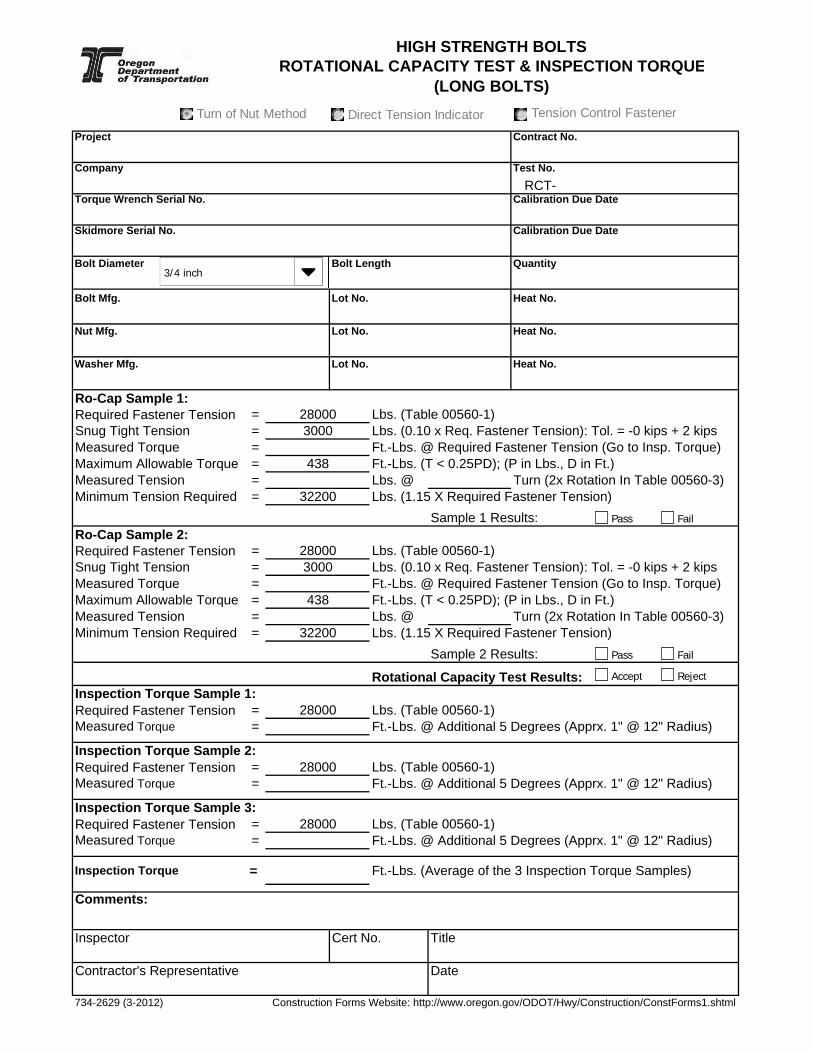
Bolt Exercise
Bolt Diameter = 3/4″
Bolt Length = 5″
Measured Torque @ Req’d Fast. Tens. = 350 ft.-lbs.
Measured Tension @ 2x Rotation = 45,000 lbs.
Complete Ro-Cap Sample 1 on the Rotational Capacity Test Form for Long Bolts.
Project Contract No.
Company Test No.
RCT-Torque Wrench Serial No. Calibration Due Date
Skidmore Serial No. Calibration Due Date
Bolt Diameter Bolt Length Quantity
Bolt Mfg. Lot No. Heat No.
Nut Mfg. Lot No. Heat No.
Washer Mfg. Lot No. Heat No.
Ro-Cap Sample 1: Required Fastener Tension = Lbs. (Table 00560-1)Snug Tight Tension = Lbs. (0.10 x Req. Fastener Tension): Tol. = -0 kips + 2 kipsMeasured Torque = Maximum Allowable Torque = Ft.-Lbs. (T < 0.25PD); (P in Lbs., D in Ft.)Measured Tension = Lbs. @ Turn (2x Rotation In Table 00560-3)Minimum Tension Required = Lbs. (1.15 X Required Fastener Tension)
Sample 1 Results:Ro-Cap Sample 2: Required Fastener Tension = Lbs. (Table 00560-1)Snug Tight Tension = Lbs. (0.10 x Req. Fastener Tension): Tol. = -0 kips + 2 kipsMeasured Torque = Maximum Allowable Torque = Ft.-Lbs. (T < 0.25PD); (P in Lbs., D in Ft.)Measured Tension = Lbs. @ Turn (2x Rotation In Table 00560-3)Minimum Tension Required = Lbs. (1.15 X Required Fastener Tension)
Sample 2 Results:
Rotational Capacity Test Results:Inspection Torque Sample 1:Required Fastener Tension = Lbs. (Table 00560-1)Measured Torque = Ft.-Lbs. @ Additional 5 Degrees (Apprx. 1" @ 12" Radius)
Inspection Torque Sample 2:Required Fastener Tension = Lbs. (Table 00560-1)Measured Torque = Ft.-Lbs. @ Additional 5 Degrees (Apprx. 1" @ 12" Radius)
Inspection Torque Sample 3:Required Fastener Tension = Lbs. (Table 00560-1)Measured Torque = Ft.-Lbs. @ Additional 5 Degrees (Apprx. 1" @ 12" Radius)
Inspection Torque = Ft.-Lbs. (Average of the 3 Inspection Torque Samples)
Comments:
Inspector Cert No. Title
Contractor's Representative Date
734-2629 (3-2012) Construction Forms Website: http://www.oregon.gov/ODOT/Hwy/Construction/ConstForms1.shtml
Ft.-Lbs. @ Required Fastener Tension (Go to Insp. Torque)
Ft.-Lbs. @ Required Fastener Tension (Go to Insp. Torque)
32200
280003000
28000
HIGH STRENGTH BOLTS ROTATIONAL CAPACITY TEST & INSPECTION TORQUE
(LONG BOLTS)
3000
438
438
32200
28000
#DIV/0!
28000
28000
Pass Fail
Accept Reject
Pass Fail
3/4 inch
Turn of Nut MethodTurn of Nut Method Direct Tension IndicatorDirect Tension Indicator Tension Control FastenerTension Control Fastener
High Strength Structural Bolts 11.1
January, 2018 33
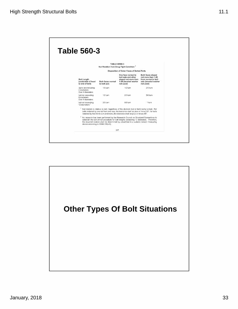
Table 560-3
Other Types Of Bolt Situations
High Strength Structural Bolts 11.1
January, 2018 34
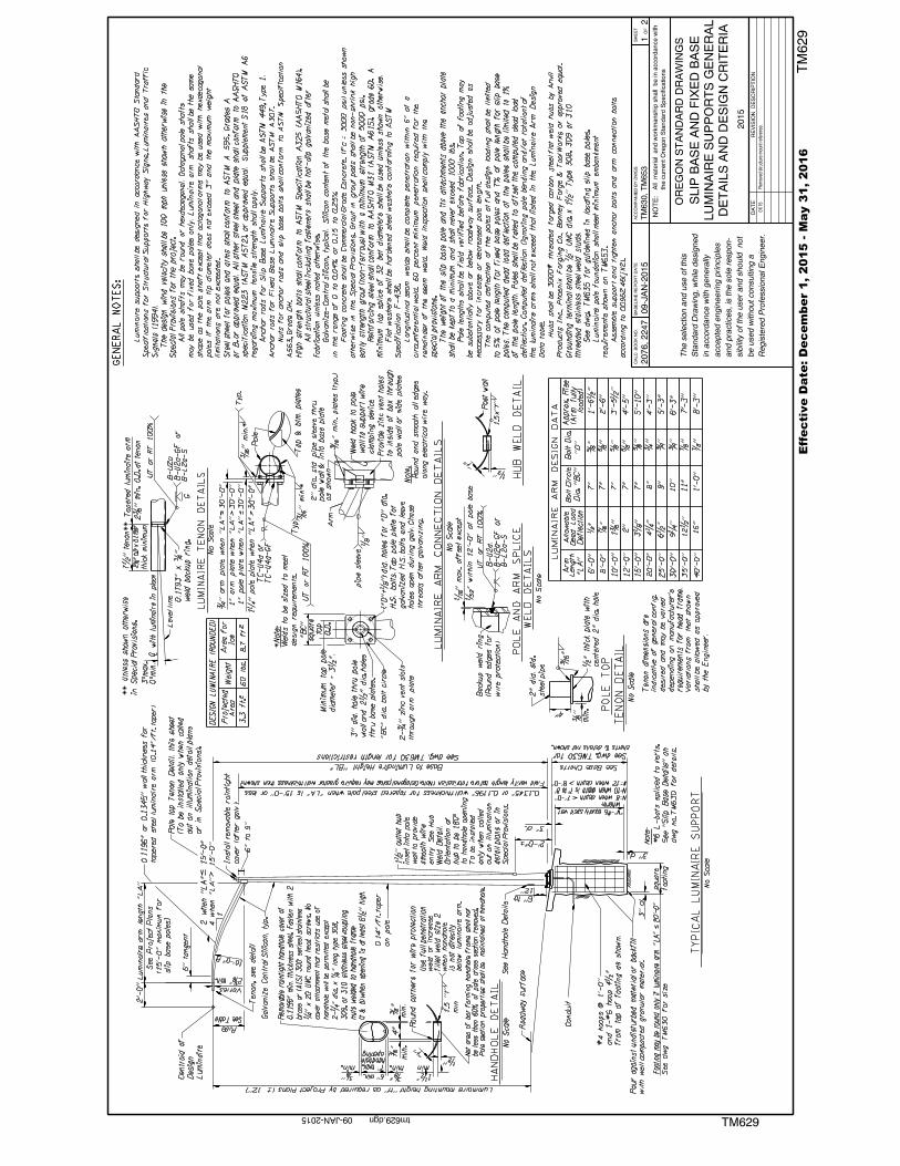
Traffic Signal & Illumination Supports (00962)
TM629 General Note
Tighten anchor bolts and arm connection bolts according to 00962.46(j)(2).


High Strength Structural Bolts 11.1
January, 2018 35
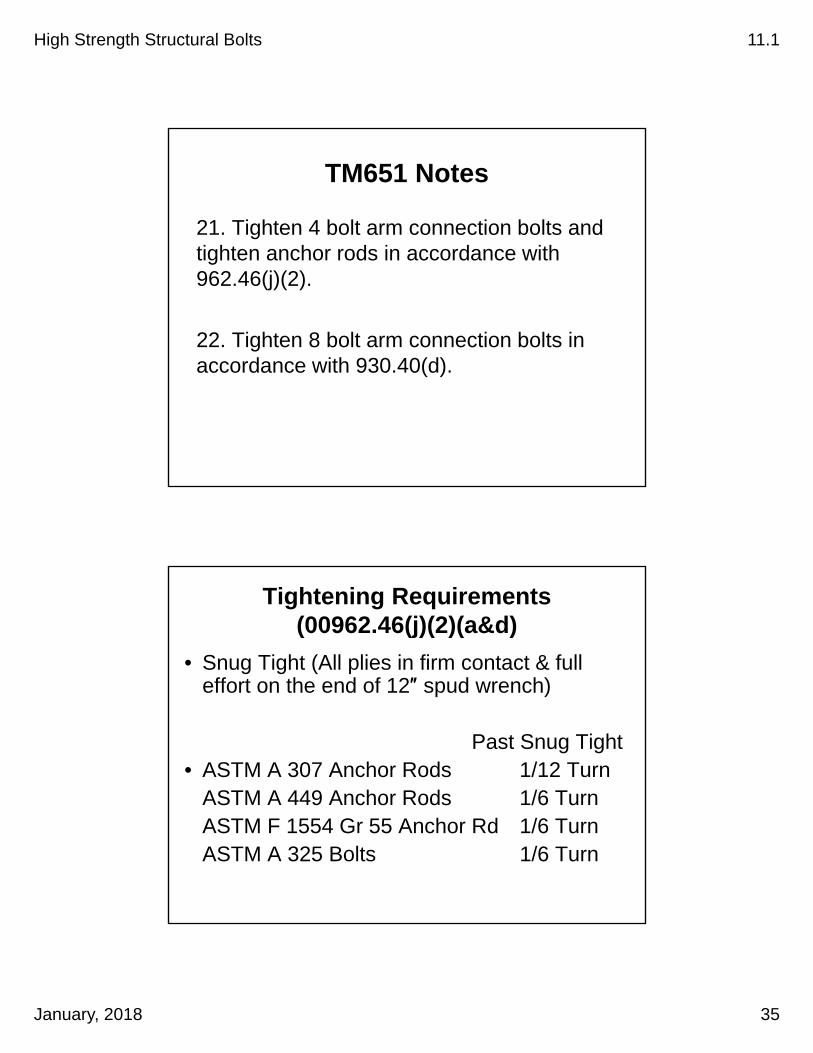
TM651 Notes
21. Tighten 4 bolt arm connection bolts and tighten anchor rods in accordance with 962.46(j)(2).
22. Tighten 8 bolt arm connection bolts in accordance with 930.40(d).
Tightening Requirements(00962.46(j)(2)(a&d)
• Snug Tight (All plies in firm contact & full effort on the end of 12″ spud wrench)
Past Snug Tight• ASTM A 307 Anchor Rods 1/12 Turn
ASTM A 449 Anchor Rods 1/6 TurnASTM F 1554 Gr 55 Anchor Rd 1/6 TurnASTM A 325 Bolts 1/6 Turn
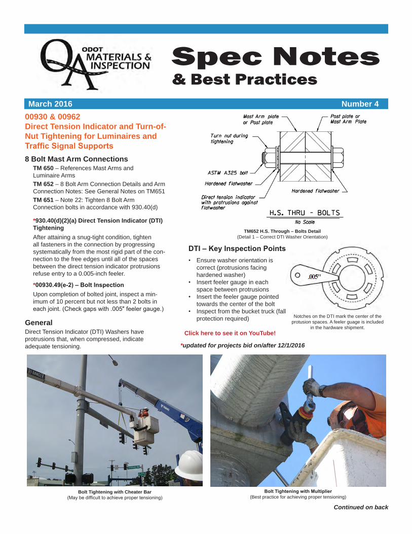
Spec Notes & Best Practices
March 2016 Number 4
Continued on back
TM652 H.S. Through – Bolts Detail(Detail 1 – Correct DTI Washer Orientation)
00930 & 00962 Direct Tension Indicator and Turn-of-Nut Tightening for Luminaires and Traffic Signal Supports8 Bolt Mast Arm Connections
TM 650 – References Mast Arms and Luminaire Arms
TM 652 – 8 Bolt Arm Connection Details and Arm Connection Notes: See General Notes on TM651
TM 651 – Note 22: Tighten 8 Bolt Arm Connection bolts in accordance with 930.40(d)
*930.40(d)(2)(a) Direct Tension Indicator (DTI) Tightening
After attaining a snug-tight condition, tighten all fasteners in the connection by progressing systematically from the most rigid part of the con-nection to the free edges until all of the spaces between the direct tension indicator protrusions refuse entry to a 0.005-inch feeler.
*00930.49(e-2) – Bolt InspectionUpon completion of bolted joint, inspect a min-imum of 10 percent but not less than 2 bolts in each joint. (Check gaps with .005″ feeler gauge.)
GeneralDirect Tension Indicator (DTI) Washers have protrusions that, when compressed, indicate adequate tensioning.
Bolt Tightening with Cheater Bar (May be difficult to achieve proper tensioning)
Bolt Tightening with Multiplier(Best practice for achieving proper tensioning)
DTI – Key Inspection Points• Ensure washer orientation is
correct (protrusions facing hardened washer)
• Insert feeler gauge in each space between protrusions
• Insert the feeler gauge pointed towards the center of the bolt
• Inspect from the bucket truck (fall protection required)
Click here to see it on YouTube!
Notches on the DTI mark the center of the protusion spaces. A feeler guage is included
in the hardware shipment.
*updated for projects bid on/after 12/1/2016

Spec Notes are prepared for inspectors by the Construction Quality Assurance Unit to provide background information around design elements and specifications. For additional Spec Notes, visit us at http://www.oregon.gov/ODOT/HWY/CONSTRUCTION/Pages/QAIndex.aspx.
If you have an idea for a Spec Notes topic, please e-mail us at [email protected] or contact us at 503.986.5453.
4 Bolt Luminaire Arm Connections & Anchor Rods (Turn-of-Nut)TM 652 – 4 Bolt Arm Connection Details and Arm Connection Notes: See General notes on TM 651
TM 650 – See details on TM 629
TM 629 – Tighten Anchor Bolts and Arm Connection bolts in ac-cordance with 962.46(j)(2)
TM 651 – Note 21: Tighten 4 Bolt Arm Connection bolts and anchor rods in accordance with 962.46(j)(2)
962.46(j)(2)(a) Anchor Rods for Signal Supports Rotate each top nut past snug as shown in (d).
962.46(j)(2)(c) High-Strength Bolts in Luminaire Arm-to-Pole Install high-strength 4-bolt connections....Rotate each top nut past snug tight as indicated in (d).
Technical ContactsTerry Thames Structure Quality [email protected]
Jaimé Viramontes, Sr. Assistant Structure Services [email protected]
Tightened BoltsPhoto shown for illustration of bolt markings only.
Signal anchor bolts require two nuts per bolt.
962.46(j)(2)(d) – Final Tightening
Connection Type Rotation Past Snug Tight
ASTM A307 Anchor Rods 30° (1/12 turn)
ASTM A449 Anchor Rods 60° (1/6 turn)
ASTM F1554 GR. 55 Anchor Rods 60° (1/6 turn)
ASTM A325 4 Bolt Connection 60° (1/6 turn)
00962.46(j)(2) – “Snug Tight” is the tighness that exists when all plies of the joint are in firm contact, and can be obtained by the full effort of a worker on the end of a 12-inch long wrench.
Turn-of-Nut Key Inspection Points• Luminaire connections must be observed/inspected at ground
level, prior to erecting pole
• Inspect leveling nuts and washers to ensure full contact with base plate prior to installation of top nut
• Be on-site for inspection
After Snug Tight, mark bolt, nut and plate prior to tightening.
Sampling of High Strength Bolts, Nuts, and Washers (NTMAG Section 00930 & 00962.10)Check to see if ODOT Materials Lab (971-673-7002) has sam-pled and tested the bolts, nuts, and washers to be used. If not previously tested, sample in the field for each lot to be used on the Project. Submit samples to the ODOT materials laboratory for testing. Do not use high strength bolts, nuts, and washers without passing laboratory report and proper quality documents.
Final tightening: Rotate Past Snug Tight per 962.46(j)(2)(a)
}1 flat = 1/6 turn
1/6 turn shown
High Strength Structural Bolts 11.1
January, 2018 36
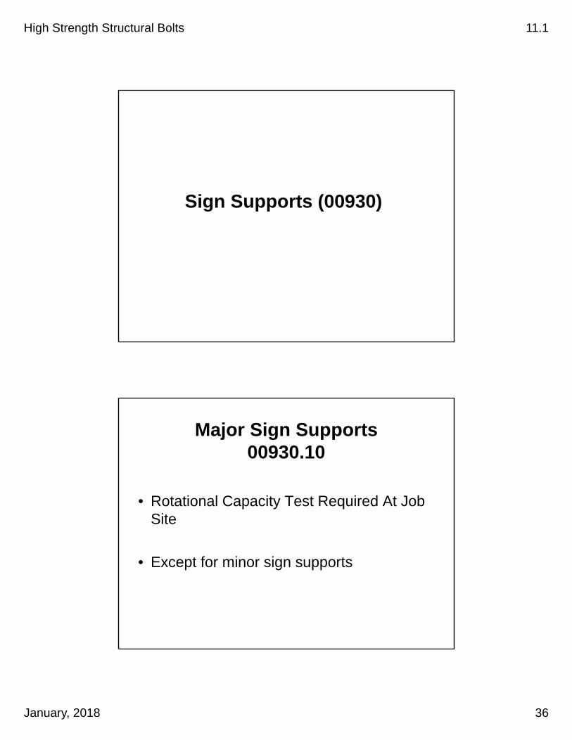
Sign Supports (00930)
Major Sign Supports00930.10
• Rotational Capacity Test Required At Job Site
• Except for minor sign supports

High Strength Structural Bolts 11.1
January, 2018 37
TM623 General Notes
All High Strength Bolts shall be considered slip critical and tightened according to 00930.40(d)(2)a unless otherwise noted.
Slip Critical Connections00930.40 (d)(2)(a)
• Install New DTI’s
• Snug Tight All
• Tighten To Full Refusal of .005 Feeler Gauge (SP00930.42(d)(2)(a))
High Strength Structural Bolts 11.1
January, 2018 38
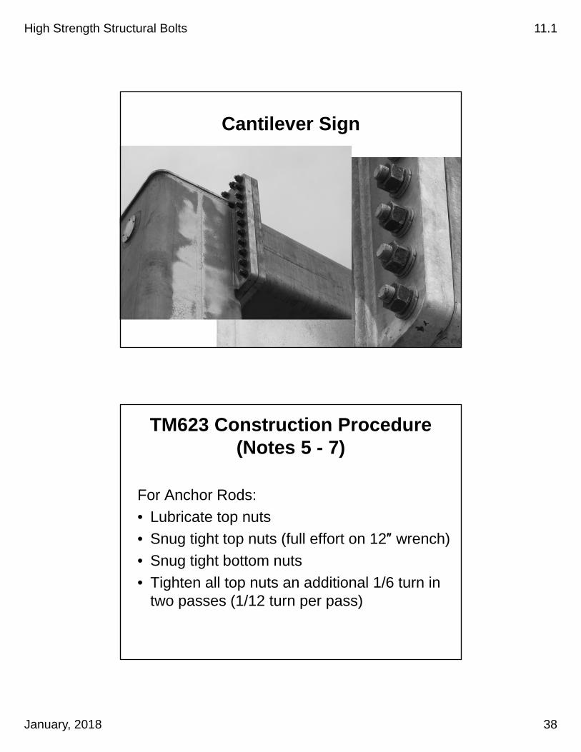
Cantilever Sign
TM623 Construction Procedure(Notes 5 - 7)
For Anchor Rods:
• Lubricate top nuts
• Snug tight top nuts (full effort on 12″ wrench)
• Snug tight bottom nuts
• Tighten all top nuts an additional 1/6 turn in two passes (1/12 turn per pass)

High Strength Structural Bolts 11.1
January, 2018 39
Cantilevered Sign Base
Resin Bonded Anchor Systems00535

High Strength Structural Bolts 11.1
January, 2018 40
Resin Bonded Anchor SystemTightening Requirements
00535.40
• Tighten to ¼ turn past snug tight
Resin Bonded Anchor SystemTest Requirements
SP00535.45
• 3 Test Anchors Prior To Production• Test To 80% of Table 535-1 Values
(For Tension Application) • Test To 50% of Table 535-1 Values
(For Shear Application)• Test 10% of Production or as Approved By EOR
(Depends on Location)

High Strength Structural Bolts 11.1
January, 2018 41


![Preloaded Bolting[1]](https://img.pdfslide.us/doc/110x75/55cf9ac2550346d033a34865/preloaded-bolting1.jpg)