Embed Size (px)
Citation preview
This document consists of 11 printed pages and 1 blank page.
DC (LK/SW) 120257/4© UCLES 2016 [Turn over
Cambridge International ExaminationsCambridge Ordinary Level
*7
93
93
74
36
6*
PHYSICS 5054/31Paper 3 Practical Test October/November 2016
2 hoursCandidates answer on the Question Paper.Additional Materials: As listed in the Confidential Instructions.
READ THESE INSTRUCTIONS FIRST
Write your Centre number, candidate number and name on all the work you hand in.Write in dark blue or black pen.You may use an HB pencil for any diagrams or graphs.Do not use staples, paper clips, glue or correction fluid.DO NOT WRITE IN ANY BARCODES.
Answer all questions.For each of the questions in Section A, you will be allowed to work with the apparatus for a maximum of 20 minutes. For the question in Section B, you will be allowed to work with the apparatus for a maximum of 1 hour.
You are expected to record all your observations as soon as these observations are made.An account of the method of carrying out the experiments is not required.
Electronic calculators may be used.You may lose marks if you do not show your working or if you do not use appropriate units.
At the end of the examination, fasten all your work securely together.The number of marks is given in brackets [ ] at the end of each question or part question.
For Examiner’s Use
1
2
3
4
Total
bestexamhelp.com
2
5054/31/O/N/16© UCLES 2016
Answer all the questions in this section.
Section A
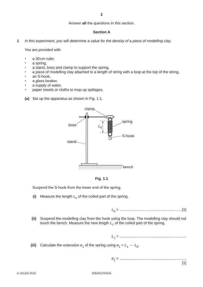
1 In this experiment, you will determine a value for the density of a piece of modelling clay.
You are provided with
• a 30 cm ruler, • a spring, • a stand, boss and clamp to support the spring, • a piece of modelling clay attached to a length of string with a loop at the top of the string, • an S-hook, • a glass beaker, • a supply of water, • paper towels or cloths to mop up spillages.
(a) Set up the apparatus as shown in Fig. 1.1.
clamp
boss
stand
L0
spring
S-hook
bench
Fig. 1.1
Suspend the S-hook from the lower end of the spring.
(i) Measure the length L0 of the coiled part of the spring.
L0 = ...........................................................[1]
(ii) Suspend the modelling clay from the hook using the loop. The modelling clay should not touch the bench. Measure the new length L1 of the coiled part of the spring.
L1 = ...............................................................
(iii) Calculate the extension e1 of the spring using e1 = L1 – L0.
e1 = ............................................................... [1]
3
5054/31/O/N/16© UCLES 2016 [Turn over
(b) Place the empty beaker below the suspended modelling clay. Lower the clamp until the modelling clay is in the beaker and the string becomes completely
slack (no tension). Pour water into the beaker until the modelling clay is fully immersed and is covered by about
1 cm of water. If the clay starts to float, then lower the clamp further. Raise the clamp slowly until the modelling clay rises from the bottom of the beaker but is still
fully immersed. Ensure that the modelling clay does not touch the sides of the beaker.
(i) Measure the new length L2 of the coiled part of the spring.
L2 = ...............................................................
(ii) Calculate the new extension e2 using e2 = L2 – L0.
e2 = ............................................................... [1]
(c) Calculate the density ρ of the modelling clay using
ρ = e1e1 – e2
× 1.0 g / cm3.
ρ = ...........................................................[2]
4
5054/31/O/N/16© UCLES 2016
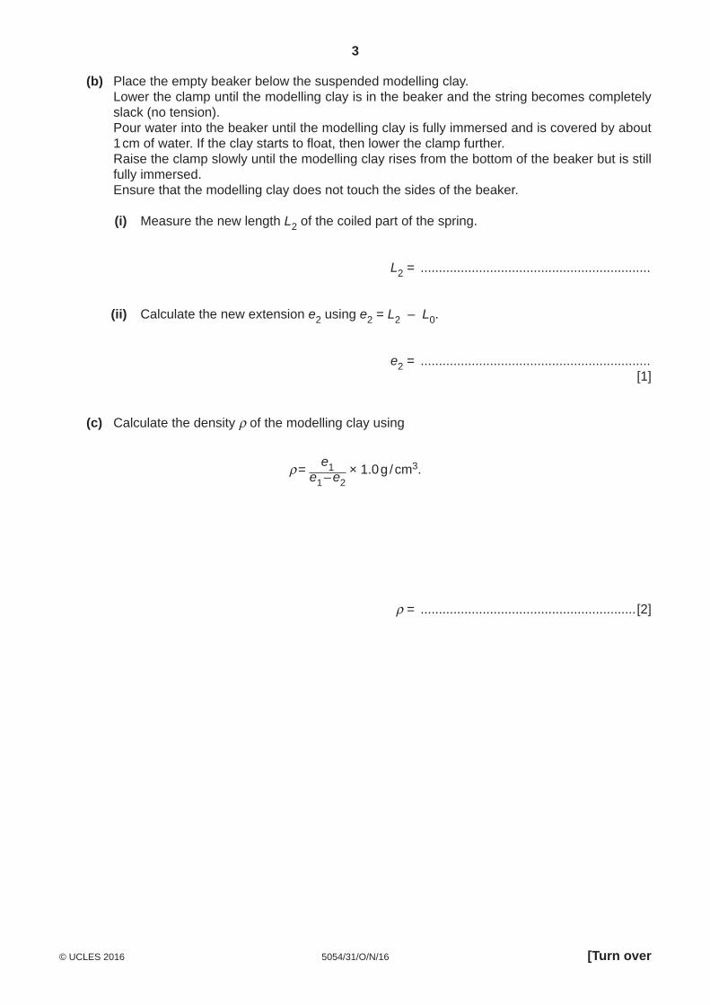
2 In this experiment, you will investigate the oscillations of a half-metre rule.
You are provided with
• a half-metre rule, • two lengths of thread with loops at one end, • two split corks, • two stands, bosses and clamps to support the split corks, • a 30 cm ruler, • an optical pin in a cork, • a stopwatch, • a set square.
(a) The Supervisor has assembled the apparatus. Do not adjust the position of the bosses and clamps on the stands. Move the loops of thread so that they are at the 10.0 cm and 40.0 cm marks on the half-metre
rule. Adjust the separation of the stands so that the two lengths of thread are vertical, as shown
in Fig. 2.1.
10.0 cm
40.0 cm
stand
clamp
boss
split cork
thread
half-metre rule
Fig. 2.1
(i) Explain how you ensured that the two lengths of thread were vertical. You may draw on Fig. 2.1 if you wish.
...........................................................................................................................................
...........................................................................................................................................
...........................................................................................................................................
.......................................................................................................................................[1]
5
5054/31/O/N/16© UCLES 2016 [Turn over
(ii) Explain how to check that the half-metre rule is horizontal.
...........................................................................................................................................
...........................................................................................................................................
.......................................................................................................................................[1]
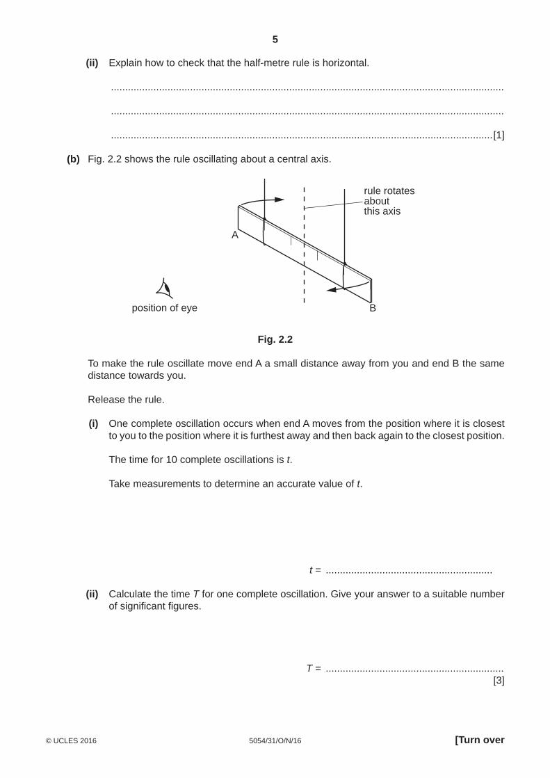
(b) Fig. 2.2 shows the rule oscillating about a central axis.
A
B
rule rotatesaboutthis axis
position of eye
Fig. 2.2
To make the rule oscillate move end A a small distance away from you and end B the same distance towards you.
Release the rule.
(i) One complete oscillation occurs when end A moves from the position where it is closest to you to the position where it is furthest away and then back again to the closest position.
The time for 10 complete oscillations is t.
Take measurements to determine an accurate value of t.
t = ...........................................................
(ii) Calculate the time T for one complete oscillation. Give your answer to a suitable number of significant figures.
T = ............................................................... [3]
6
5054/31/O/N/16© UCLES 2016
3 In this experiment, you will investigate the resistance of a diode at two values of current.
You are provided with
• a power supply, • a switch, • a resistor labelled Y, • a 10 Ω resistor, • a diode, • an ammeter, • a voltmeter, • connecting leads.
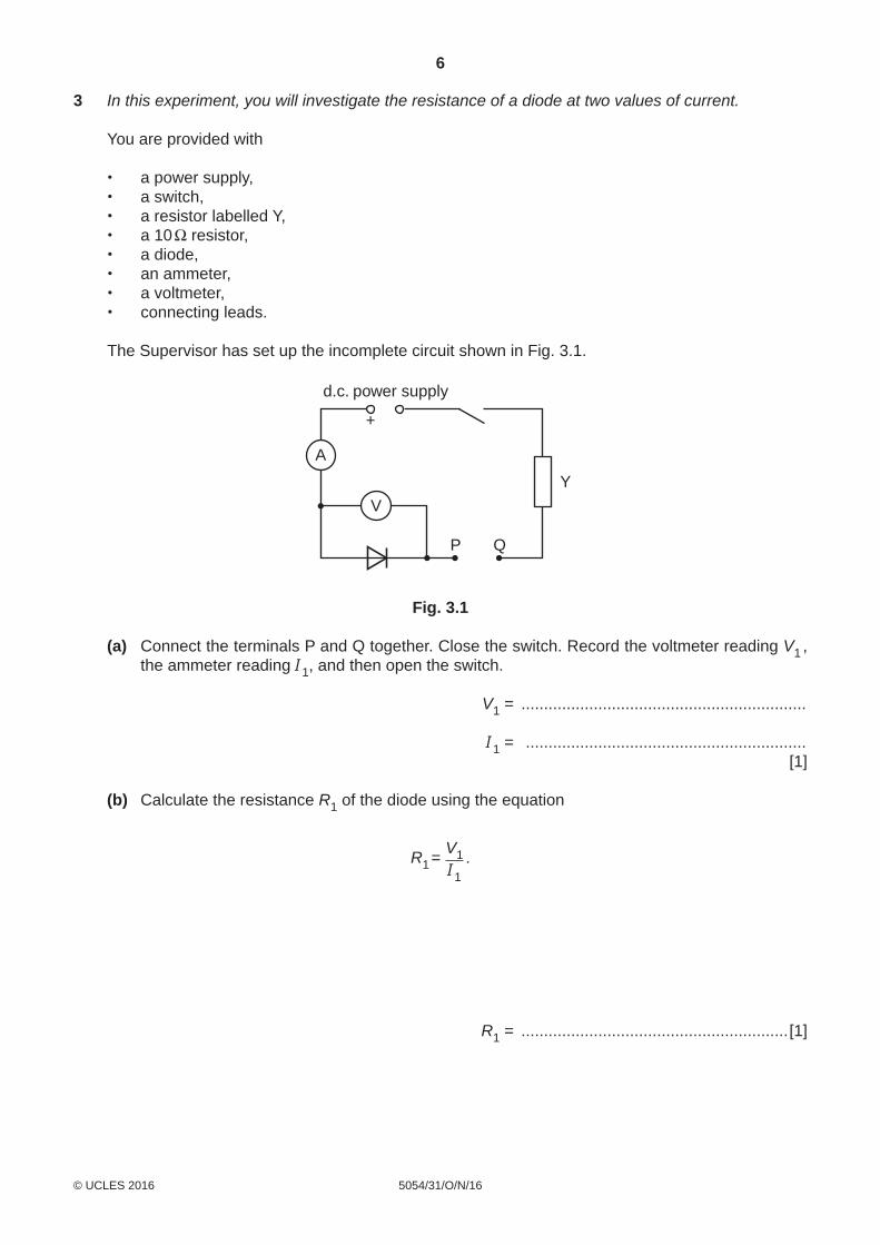
The Supervisor has set up the incomplete circuit shown in Fig. 3.1.
A
V
+
d.c. power supply
P Q
Y
Fig. 3.1
(a) Connect the terminals P and Q together. Close the switch. Record the voltmeter reading V1 , the ammeter reading I1, and then open the switch.
V1 = ...............................................................
I1 = .............................................................. [1]
(b) Calculate the resistance R1 of the diode using the equation
R1 = V1I1
.
R1 = ...........................................................[1]
7
5054/31/O/N/16© UCLES 2016 [Turn over
(c) Disconnect the terminals P and Q. Connect the 10 Ω resistor between P and Q. Close the switch. Record the voltmeter reading V2, the ammeter reading I2, and then open the switch.
V2 = ...............................................................
I2 = .............................................................. [1]
(d) Calculate the new resistance R2 of the diode using the equation
R2 = V2I2
.
R2 = ...........................................................[1]
(e) By changing the resistance between P and Q, the current in the circuit changes. State how this change in current affects the voltage across the diode and the resistance of the diode.
...................................................................................................................................................
...................................................................................................................................................
...............................................................................................................................................[1]
8
5054/31/O/N/16© UCLES 2016
Section B
4 In this experiment, you will determine the focal length of a converging lens.
You are provided with
• a converging lens, • an illuminated cross-wire object, • a lens holder, • a light source, • a screen, • a metre rule, • a set square.
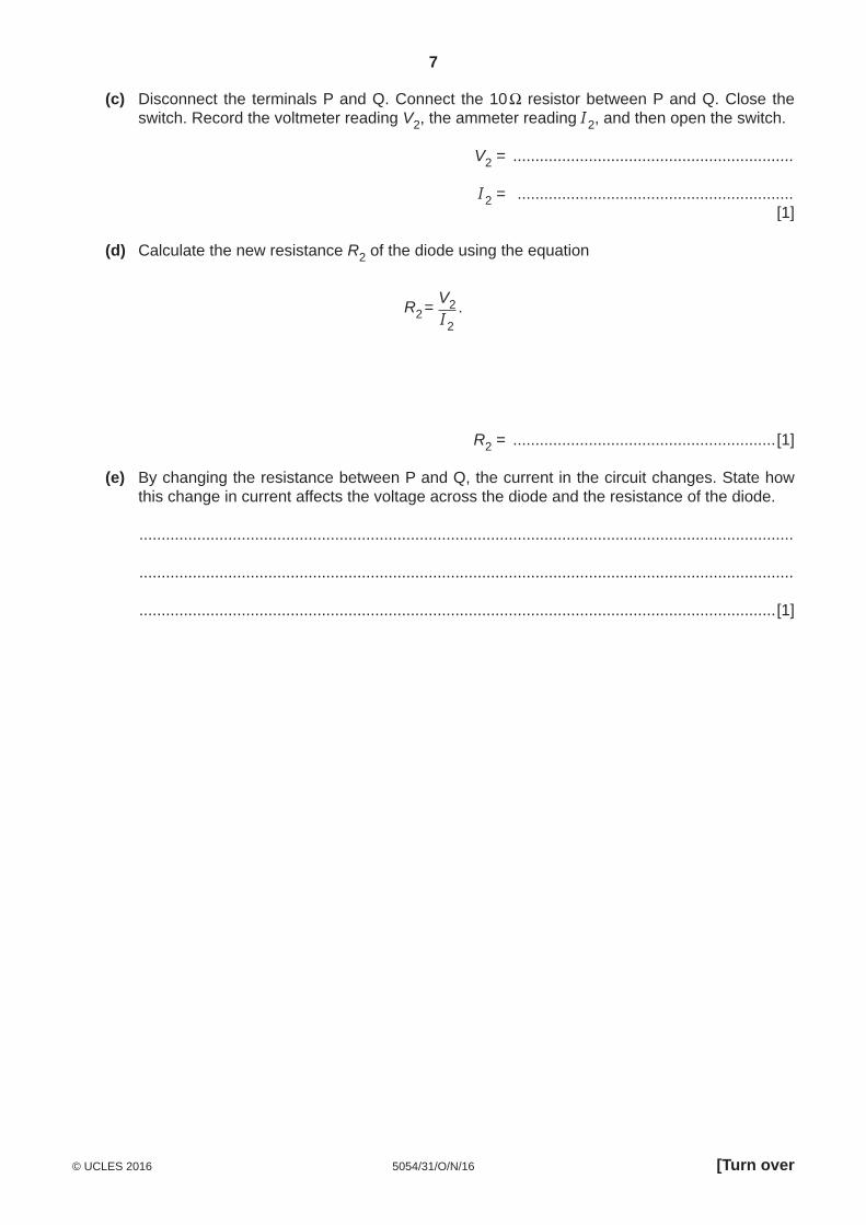
(a) Set up the apparatus as shown in Fig. 4.1.
screen
metre rule
lens inholder
light source
D
object distance
cross-wireobject
Fig. 4.1
The cross-wire object is at the 0.0 cm end of the rule and the screen is at the 100.0 cm end.
(i) By only changing the position of the lens obtain an image on the screen that is smaller than the object. Describe the technique that you use to obtain an image that is in sharp focus.
...........................................................................................................................................
...........................................................................................................................................
.......................................................................................................................................[1]
(ii) Determine an accurate value for the distance uS between the object and the lens when the image is smaller than the object and is in sharp focus on the screen.
uS = ...........................................................[2]
9
5054/31/O/N/16© UCLES 2016 [Turn over
(b) By only changing the position of the lens obtain an image on the screen that is larger than the object.
(i) Determine the new value for the object distance uL when the image is larger than the object and in sharp focus on the screen.
uL = ...............................................................
(ii) In order to change from an image that is smaller than the object to an image that is larger than the object the lens has been moved a distance d.
1. Calculate d using d = uS – uL.
d = ...............................................................
2. Calculate y using y = D 2 – d 2, where D is the distance between the object and the screen.
y = ............................................................... [2]
10
5054/31/O/N/16© UCLES 2016
(c) Repeat (a) (ii) and (b) using different values of D in the range 60 cm G D G 100 cm. The object should remain at the 0.0 cm mark on the rule and the position of the screen should be changed to give different values of D. Record your results for D, uS, uL, d and y in the table of Fig. 4.2. Include headings in your table and your initial results from (a) (ii) and (b).
Fig. 4.2 [4]
(d) Using the grid opposite, plot a graph of y / cm2 (y-axis) against D / cm (x-axis). Draw the straight line of best fit. [4]
(e) (i) Determine the gradient G of your graph.
G = ...............................................................
(ii) Calculate the numerical value f of the focal length of your lens using f = G4 .
f = ............................................................... [2]
11
5054/31/O/N/16© UCLES 2016

12
5054/31/O/N/16© UCLES 2016
Permission to reproduce items where third-party owned material protected by copyright is included has been sought and cleared where possible. Every reasonable effort has been made by the publisher (UCLES) to trace copyright holders, but if any items requiring clearance have unwittingly been included, the publisher will be pleased to make amends at the earliest possible opportunity.
To avoid the issue of disclosure of answer-related information to candidates, all copyright acknowledgements are reproduced online in the Cambridge International Examinations Copyright Acknowledgements Booklet. This is produced for each series of examinations and is freely available to download at www.cie.org.uk after the live examination series.
Cambridge International Examinations is part of the Cambridge Assessment Group. Cambridge Assessment is the brand name of University of Cambridge Local Examinations Syndicate (UCLES), which is itself a department of the University of Cambridge.
BLANK PAGE