Embed Size (px)
Citation preview
*0602334107*
This document consists of 11 printed pages and 1 blank page.
DC (CW/FD) 131603/2© UCLES 2017 [Turn over
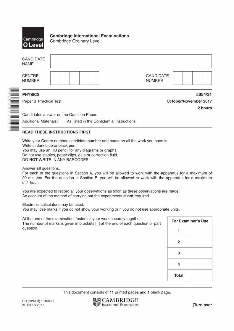
Cambridge International ExaminationsCambridge Ordinary Level
PHYSICS 5054/31Paper 3 Practical Test October/November 2017 2 hoursCandidates answer on the Question Paper.Additional Materials: As listed in the Confidential Instructions.
READ THESE INSTRUCTIONS FIRST
Write your Centre number, candidate number and name on all the work you hand in.Write in dark blue or black pen.You may use an HB pencil for any diagrams or graphs.Do not use staples, paper clips, glue or correction fluid.DO NOT WRITE IN ANY BARCODES.
Answer all questions.For each of the questions in Section A, you will be allowed to work with the apparatus for a maximum of 20 minutes. For the question in Section B, you will be allowed to work with the apparatus for a maximum of 1 hour.
You are expected to record all your observations as soon as these observations are made.An account of the method of carrying out the experiments is not required.
Electronic calculators may be used.You may lose marks if you do not show your working or if you do not use appropriate units.
At the end of the examination, fasten all your work securely together.The number of marks is given in brackets [ ] at the end of each question or part question.
For Examiner’s Use
1
2
3
4
Total
2
5054/31/O/N/17© UCLES 2017
Answer all the questions in this section.
Section A
1 In this experiment, you will investigate the oscillations of a mass connected to springs.
You are provided with
• an arrangement of two springs that are connected in series, • a single spring, • a mass labelled M, • a stand, boss and clamp from which to suspend the springs, • a stopwatch, • a second clamp and boss.
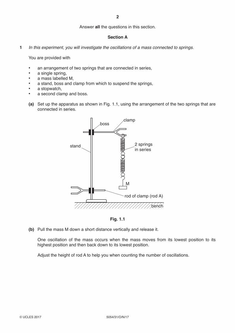
(a) Set up the apparatus as shown in Fig. 1.1, using the arrangement of the two springs that are connected in series.
stand
boss
rod of clamp (rod A)
2 springsin series
M
clamp
benchbench
Fig. 1.1
(b) Pull the mass M down a short distance vertically and release it.
One oscillation of the mass occurs when the mass moves from its lowest position to its highest position and then back down to its lowest position.
Adjust the height of rod A to help you when counting the number of oscillations.
3
5054/31/O/N/17© UCLES 2017 [Turn over
(i) Describe how you use rod A to ensure that you count complete oscillations made by the mass. You may draw a diagram if you wish.
...........................................................................................................................................
...........................................................................................................................................
...........................................................................................................................................
...........................................................................................................................................
(ii) The time for 10 oscillations is t1. Take measurements to determine an accurate value of t1.
t1 = ...............................................................
(iii) Calculate the time T1 for one oscillation. Give your answer to an appropriate number of significant figures.
T1 = ............................................................... [3]
(c) Replace the double spring arrangement by the single spring. Suspend the mass M from the single spring.
Repeat (b)(ii) and (b)(iii) so that new values are obtained for the time t2 for 10 oscillations and the time T2 for one oscillation.
t2 = ...............................................................
T2 = ............................................................... [1]
(d) Calculate TT
1
2 .
TT
1
2 = ...........................................................[1]
4
5054/31/O/N/17© UCLES 2017
2 In this experiment, you will investigate a circuit containing a light-dependent resistor.
You are provided with
• a power supply, • a switch, • a light-dependent resistor, • a resistor labelled R, • a voltmeter, • connecting leads, • a 250 cm3 glass beaker filled with water, • a light source, • a container labelled A containing a small amount of blue liquid, • safety glasses or goggles, • a 5 cm3 plastic syringe, • a stirrer, • paper towels or cloths to mop up spillages.
When using the blue liquid:
• If any liquid comes into contact with your skin wash off immediately with water. • It is recommended that you wear safety goggles / glasses.
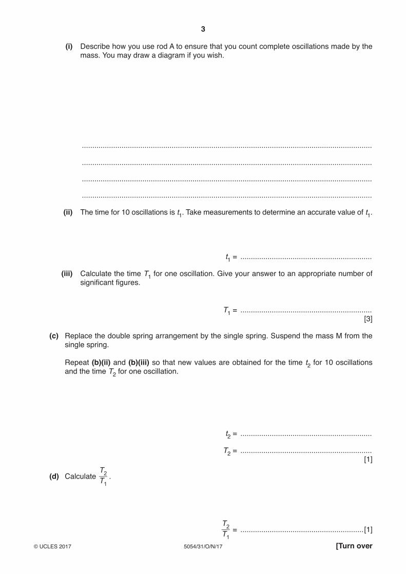
The Supervisor has set up the apparatus as shown in Fig. 2.1. Do not alter the position of the light source or the position of the light-dependent resistor (LDR).
V
lightsource
water beaker
R
Blu-tack
d.c. powersupply
LDR
Fig. 2.1
(a) Switch on the light source and close the switch in the electrical circuit.
Record the voltmeter reading V1.
V1 = ...........................................................[1]
5
5054/31/O/N/17© UCLES 2017 [Turn over
(b) (i) Use the syringe to add 1.0 cm3 (1 ml) of the blue liquid from container A to the water in the glass beaker and stir.
Record the new voltmeter reading V2.
V2 = ...............................................................
(ii) Repeat (b)(i) to add a further 1.0 cm3 of the blue liquid.
Record the new voltmeter reading V3.
V3 = ............................................................... [1]
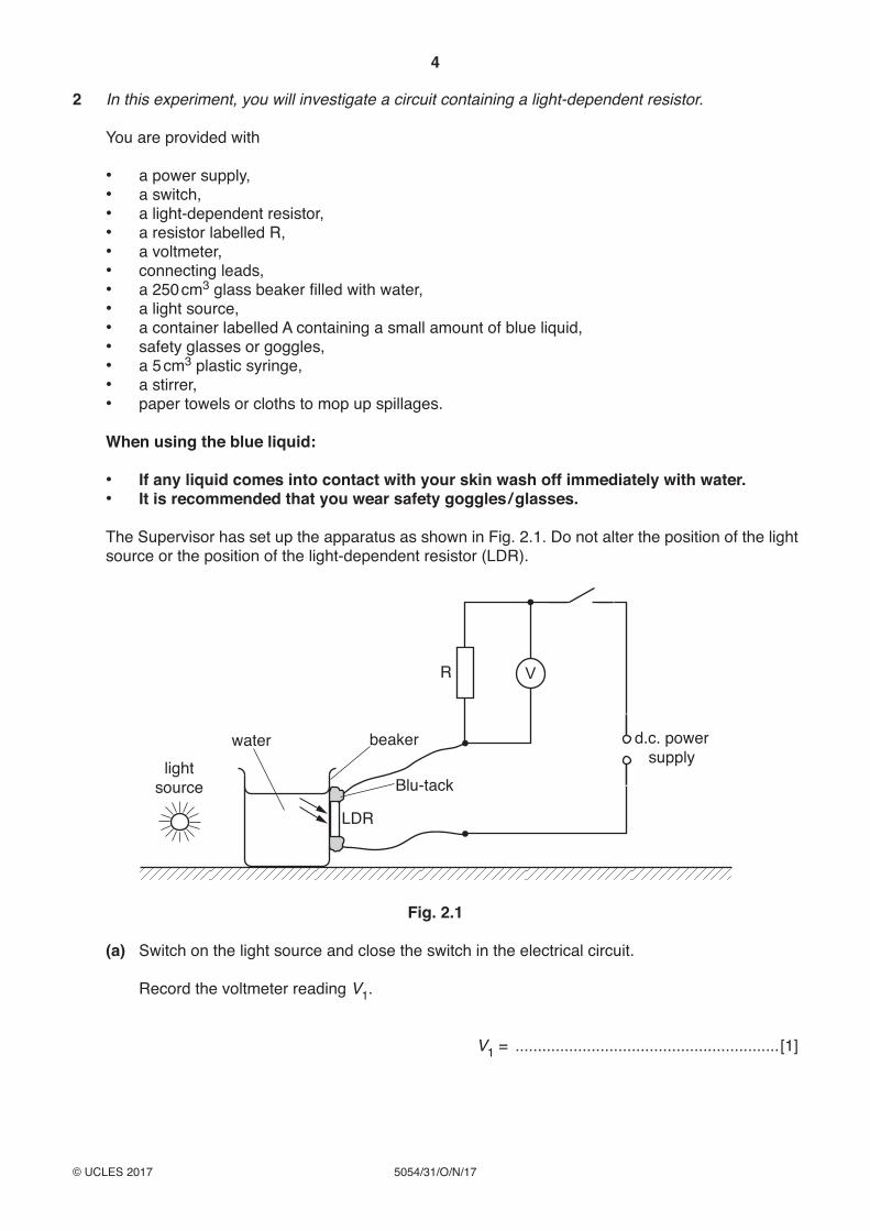
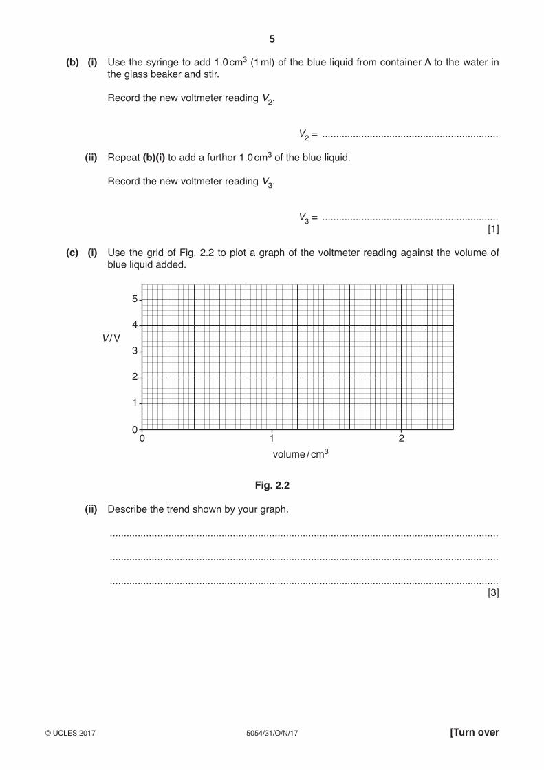
(c) (i) Use the grid of Fig. 2.2 to plot a graph of the voltmeter reading against the volume of blue liquid added.
1
00 1
volume / cm32
2
3
4
5
V / V
Fig. 2.2
(ii) Describe the trend shown by your graph.
...........................................................................................................................................
...........................................................................................................................................
...........................................................................................................................................[3]
6
5054/31/O/N/17© UCLES 2017
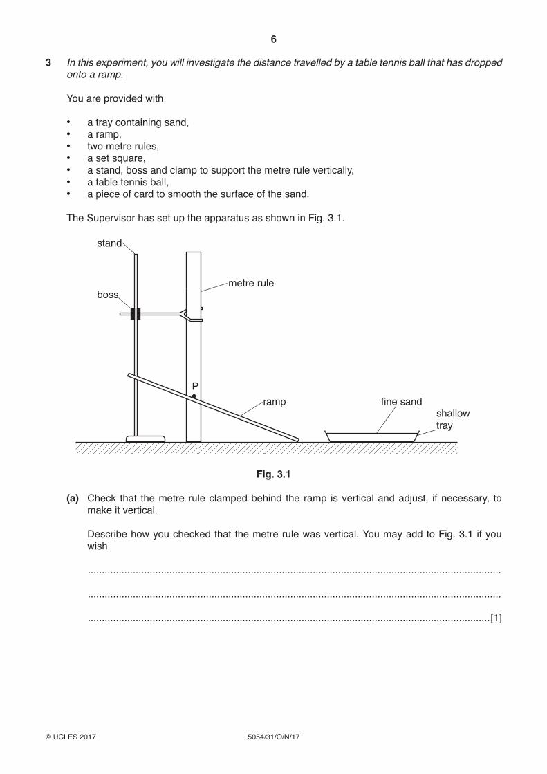
3 In this experiment, you will investigate the distance travelled by a table tennis ball that has dropped onto a ramp.
You are provided with
• a tray containing sand, • a ramp, • two metre rules, • a set square, • a stand, boss and clamp to support the metre rule vertically, • a table tennis ball, • a piece of card to smooth the surface of the sand.
The Supervisor has set up the apparatus as shown in Fig. 3.1.
stand
bossmetre rule
ramp fine sandshallowtray
P
Fig. 3.1
(a) Check that the metre rule clamped behind the ramp is vertical and adjust, if necessary, to make it vertical.
Describe how you checked that the metre rule was vertical. You may add to Fig. 3.1 if you wish.
...................................................................................................................................................
...................................................................................................................................................
...............................................................................................................................................[1]
7
5054/31/O/N/17© UCLES 2017 [Turn over
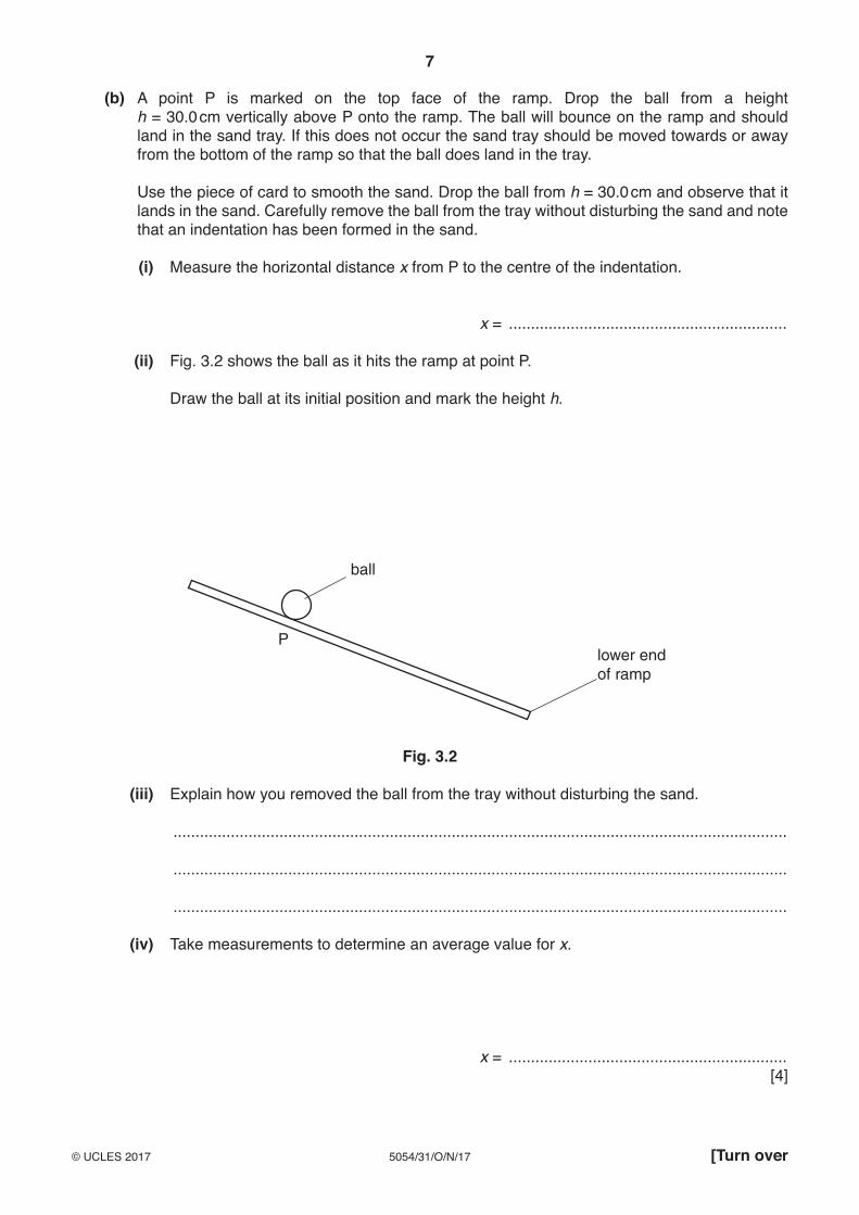
(b) A point P is marked on the top face of the ramp. Drop the ball from a height h = 30.0 cm vertically above P onto the ramp. The ball will bounce on the ramp and should land in the sand tray. If this does not occur the sand tray should be moved towards or away from the bottom of the ramp so that the ball does land in the tray.
Use the piece of card to smooth the sand. Drop the ball from h = 30.0 cm and observe that it lands in the sand. Carefully remove the ball from the tray without disturbing the sand and note that an indentation has been formed in the sand.
(i) Measure the horizontal distance x from P to the centre of the indentation.
x = ...............................................................
(ii) Fig. 3.2 shows the ball as it hits the ramp at point P.
Draw the ball at its initial position and mark the height h.
P
ball
lower endof ramp
Fig. 3.2
(iii) Explain how you removed the ball from the tray without disturbing the sand.
...........................................................................................................................................
...........................................................................................................................................
...........................................................................................................................................
(iv) Take measurements to determine an average value for x.
x = ............................................................... [4]
8
5054/31/O/N/17© UCLES 2017
Section B
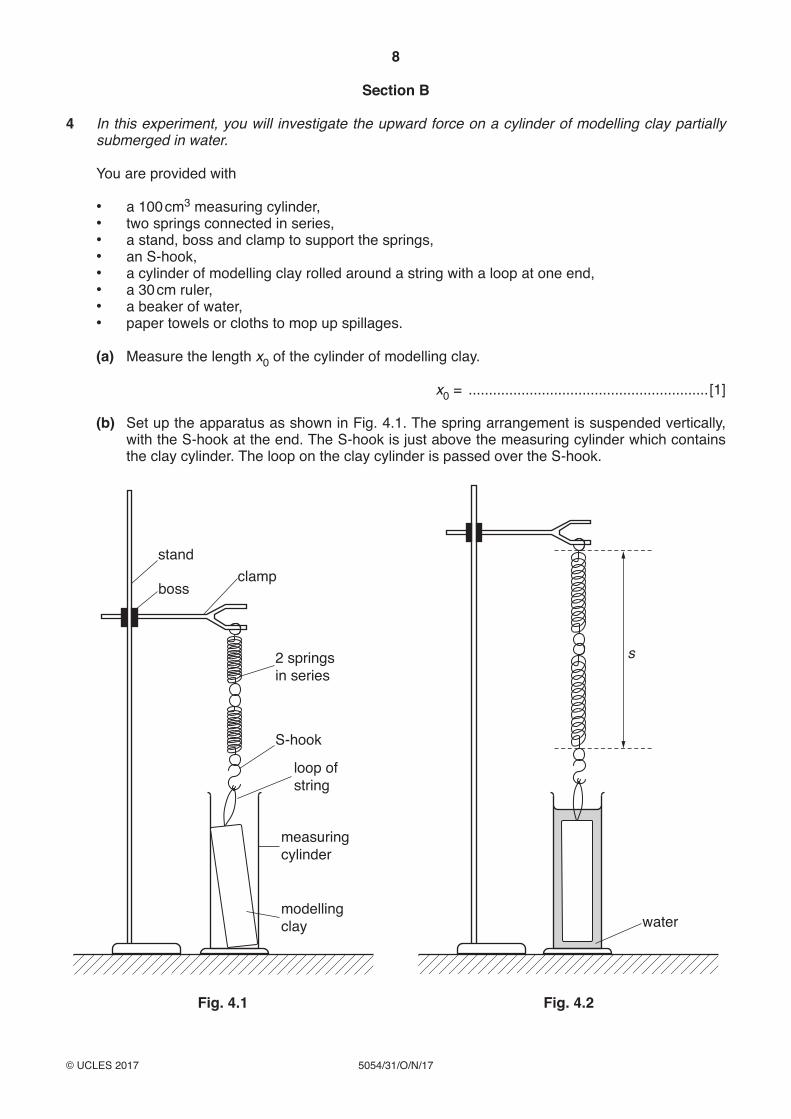
4 In this experiment, you will investigate the upward force on a cylinder of modelling clay partially submerged in water.
You are provided with
• a 100 cm3 measuring cylinder, • two springs connected in series, • a stand, boss and clamp to support the springs, • an S-hook, • a cylinder of modelling clay rolled around a string with a loop at one end, • a 30 cm ruler, • a beaker of water, • paper towels or cloths to mop up spillages.
(a) Measure the length x0 of the cylinder of modelling clay.
x0 = ...........................................................[1]
(b) Set up the apparatus as shown in Fig. 4.1. The spring arrangement is suspended vertically, with the S-hook at the end. The S-hook is just above the measuring cylinder which contains the clay cylinder. The loop on the clay cylinder is passed over the S-hook.
stand
boss
loop ofstring
S-hook
2 springsin series
clamp
modellingclay
measuringcylinder
water
s
Fig. 4.1 Fig. 4.2
9
5054/31/O/N/17© UCLES 2017 [Turn over
Note that in this experiment you will not be using the scale on the measuring cylinder.
(c) Pour water into the measuring cylinder until the clay cylinder is fully submerged and there is a depth of approximately 2 cm of water above the cylinder. Raise the boss until the base of the clay cylinder is about 1 cm above the bottom of the measuring cylinder, and the clay cylinder is fully submerged. Make minor adjustments to the apparatus to make sure that the clay cylinder does not touch the measuring cylinder and is still submerged in the water. The apparatus should be as shown in Fig. 4.2.
Explain how you checked that the clay cylinder was not touching the sides of the measuring cylinder.
...................................................................................................................................................
...................................................................................................................................................
...............................................................................................................................................[1]
(d) Measure the length s between the upper and lower loops on the spring, as shown in Fig. 4.2.
s = ...........................................................[1]
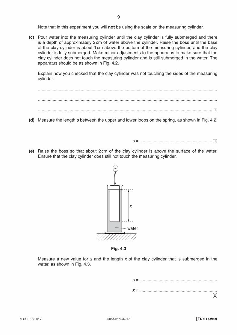
(e) Raise the boss so that about 2 cm of the clay cylinder is above the surface of the water. Ensure that the clay cylinder does still not touch the measuring cylinder.
water
x
Fig. 4.3
Measure a new value for s and the length x of the clay cylinder that is submerged in the water, as shown in Fig. 4.3.
s = ...............................................................
x = ............................................................... [2]
10
5054/31/O/N/17© UCLES 2017
(f) Continue to raise the boss to obtain a series of values of s and x.
Record your results in the table of Fig. 4.4.
Include units in the headings of the table and your results from (a), (d) and (e).
Fig. 4.4 [4]
(g) Using the grid opposite, plot a graph of s / cm (y-axis) against x / cm (x-axis).
Draw the straight line of best fit. [4]
(h) Determine the gradient G of your graph.
Give your answer to an appropriate number of significant figures.
G = ...........................................................[2]
11
5054/31/O/N/17© UCLES 2017
12
5054/31/O/N/17© UCLES 2017
Permission to reproduce items where third-party owned material protected by copyright is included has been sought and cleared where possible. Every reasonable effort has been made by the publisher (UCLES) to trace copyright holders, but if any items requiring clearance have unwittingly been included, the publisher will be pleased to make amends at the earliest possible opportunity.
To avoid the issue of disclosure of answer-related information to candidates, all copyright acknowledgements are reproduced online in the Cambridge International Examinations Copyright Acknowledgements Booklet. This is produced for each series of examinations and is freely available to download at www.cie.org.uk after the live examination series.
Cambridge International Examinations is part of the Cambridge Assessment Group. Cambridge Assessment is the brand name of University of Cambridge Local Examinations Syndicate (UCLES), which is itself a department of the University of Cambridge.
BLANK PAGE