Embed Size (px)
Citation preview

KR0100937
KAERI/RR-2078/2000
7HW1*1- ^£(2000)
Development of Contact Failure Analysis Technology
- First Year(2000) Report -

KAERI/RR-2078/2000
l - 2000
2001
7)

2.
I.
II.
Sit)-.
5-7-7} 3711 #«J
# ^ 1 tfl«|.
in.-i: JL^sfJL

IV.
Square Punch, Wedge ^ Cylinder^ ^ ^ ^ . S . ^ -^-^
J T . ^ ^ . ^ ^ tL ^^T- ^ S q u a r e P u n c h 6\]
o)
- fl
-1: 33SMI . o]
o]-g-*V ^ o^
111

A
v.
IV

SUMMARY
I. Project Title
Development of Contact Failure Analysis Technology
II. Objective and Importance of the Project
This research focuses primarily on the mechanical analysis of contact failure, which
can be advocated as an originality of the project. Fretting failure is presently considered for
the contact failure, which has been widely found in the nuclear industry (e.g., fuel, steam
generator, piping systems etc.) as well as in the mechanical industry (e.g., gear, press fits,
joints with bolt and nuts, etc.). A contacting part is often found in the structural design of
mechanical components, and the failure due to the contact is intrinsically inevitable during
service of the components. However, if we can identify the parameters that affect the failure
and procure a tool for analyzing the parameters, the failure can be controlled and reduced, in
other words, a design guideline for alleviating the contact failure is to be implemented. The
purpose of this research is to develop such a realistic methodology. To this end, it is intended
to draw a method of analyzing and controlling the contact failure using solid mechanics
theory as well as experiments. Including the above, wear and cracking failure due to contact
reduce the design life of the mechanical components considerably. Therefore, the importance
of present research cannot be underestimated since it can be used for developing a
technology of evaluating and extending the design life.
III. Scope and Contents of Project
In this research, wear and cracking failure are considered as a contact failure. As the
parameters for explaining these failures, friction energy dissipation from the contact
surface is referred to for wear, while stress intensity factors of a surface breaking crack is
studied for the cracking failure. It is the first step to evaluate contact tractions to obtain the
friction energy and the stress intensity factors which need to be quantified for the analysis
of contact failure. On the other hand, contact failure experiments are also carried out using
the fretting wear tester that has been developed for fretting test of fuel rod. The
experimental results are analyzed and compared with the theoretical analysis. For the

experimental analysis, an algorithm of calculating the wear volume is newly developed,
which gives further accurate result compared with the conventionally used method.
IV. Result of Project
Contact tractions are affected by the geometry of contacting bodies. In the present
research, square punch, wedge and cylinders are considered as the geometry. Among the
geometry, a square punch with rounded corners is basically used since it can give
generalization of the geometry. Normal traction profile is obtained in the case of the rounded
punch, and shear tractions are evaluated under the partial slip regime by using the influence
function method.
Multiplication of the shear traction and slip displacement in the slip region of the
contact provides the friction energy dissipation from the contact. Since the trace of the shear
force influences the amount of the dissipated energy, a desirable trace of the shear force may
be supposed to reduce the energy dissipation. If wear is explained as the energy dissipation,
it can be possible to suggest a certain trace of the shear force (or relative motion of the
contacting bodies).
Internal stresses are evaluated from the contact normal and shear tractions, which are to
be used for calculating the stress intensity factors of a surface breaking crack emanated from
the contact surface. Fretting condition is composed when shear force is exerted cyclically to
the contacting bodies. The stress intensity factors, K\ and Ku, are investigated during the
cyclic shear. It is found that a period of crack opening exists during a shear cycle, which is
effective for crack growing. So, to reduce the period can be a method for restraining the
cracking failure. On the other hand, the stress intensity factors vary if the roundness of the
punch changes. This result provides an idea that there can exist a desirable shape of the
contacting body, which can restrain the cracking failure. It must be a very valuable outcome
since we can control the cracking failure by changing the shape of contacting bodies in the
design stage.
In the experiment, fretting wear tester is used with the specially designed specimen.
Stationary specimen similar to the tensile test specimen is indented by a moving specimen,
which has the shape of rounded punches with three different corner radii. Wear of the contact
surface are observed in detail, which show typical shape following the partial and gross slip
regimes. In addition, an algorithm for evaluating the wear volume is newly developed using

the signal processing technique and the Fast Fourier Transform (FFT).
V. Proposal for Application
Methods developed for the contact tractions and the internal stresses can be used not
only for the analysis of the fuel fretting failure which KNFC is presently interested in, but
also for the design of the contact components which may be widely occurred during the
design task conducted by the industry including KEPCO. The fretting wear experiment
technology can be used for the similar experiments, which may be planned by the industry
where wear is brought into focus. Procurement of a design guideline and evaluation of the
structure lifetime are the subjects of the project, which can be extended from the present
work.
VII

CONTENTS
SUBMISSION
SUMMARY
CONTENTS
LIST OF FIGURES
CHAPTER 1 Introduction 1
CHAPTER 2 Research Subjects 3
SECTION 1 Analysis of Contact Tractions 3
1. Overview 3
2. Normal Traction 6
3. Shear Traction • 8
4. Numerical Analysis 12
5. Results and Discussion 17
SECTION 2 Method of Theoretical Analysis of Contact Failure 24
1. Overview 24
2. Friction Energy Dissipation 25
3. Crack Analysis 27
SECTION 3 Experiments and Calculation of Wear Volume 43
1. Fretting Wear Tester 43
2. Experimental Method and Specimen 44
3. Results 47
4. Calculation of Wear Volume • • 50
CHAPTER 3 Concluding Remarks 59
CHAPTER 4 References 60
VIII

SUMMARY
CONTENTS
4 1
4] 2
46.
7.
8.
9.
10.
2 ^
4.
5.
6.
3 *i
5.
6.
7.
8.
41 3
4 4
3
3
3
6
8
12
17
24
24
25
27
43
43Al^! : ' ' ' 44
47
Tfl-S: 50
59
60
IX

1.1.
1.2.
1.3.
1.4.
1.5.
1.6. Mindlin-Cattaneo
1.7.
1.8.
1.9.
2.1.
2.2.
2.3.
2.4.
2.5.
2.6.
2.7.
2.8. 51^1
^•(at a/w = 0.00 \,l/w = 0.56).
2.9. l/w oil 4^ - ^ ^ V ^ ft 4 ° l
0.001,0 = 30°).
3J 3.1.
3.2.
3.3. H
y o V # .
HoV
= 0.005).
^5}-(at
3.4.
3.5.
3.6.
15/imSl
a>^]f- 2.5 mm).
50 N, $.%• 400 /im ?
# (a) 2.5 mm, (b) 15 mm.
37l (a) 30 N, (b) 50

3.7.
3.8.
3.9.
3.10.
3.11.
3.12.
3.13.
30 , 20
3.10
3.10
(64)^
XI

M
^(fretting failure)^ ^- #^)1 ^ sfq- Sfe # tfcontact
tb ^ ^ - i - «>7i] 3 J ! °11- ^ # ^ ^ ° l l A i ^ ^ ^lH^(Gross Slip £ ^ GrossSliding)
OH- a-^- nlii^(PartialSlip) M^ &% £ Q ^ ] & ^n) l ^H1 flfl
1:711
31
o)
^ ^ ^ ^ . 5 1 HL l ^ . Bj-tH^ ^ ^ 1 ^ ^ ^ # 7
$14.

Si71
Sltr 7)a-i-
27))
SEM ^ #

2 S S
1. 7fl
0} S\H
7> ^-ffe
0
1 3.71
(incomplete contact)^5f £•??•£]7l£.
Ufl

^5} 7}- r^^Cf. ^1^1
3717> ^ # * B ^ *?-$•$; ^ ^ - 1 - S } ^ ^^(complete contact)^
si4.
7}
[8].
(partial slip) ^^1^1 «f l^^ H ^ ^ H # ^ l | flf ^ 4
Mindlin[10]4
Cattaneo^l fil«fl
-^r -S-

l.l. e } - ^ 31 *H
nsjuj-
3L
^^(influence function) ^ #
^ Bentall4 Johnson[13H
*>°i x ^

\. y
2.
7]-
0)
Dunders

0)
= 0) Sfe
-dt, (4)
(5)
P ;r-2^0-sin20o
{TC -2<j>0)cos<j>
tan-—^-tan-—-2 2
(6)
(7)

sin a)(8)
o) S\5L, alb = 0.9^ i f l^S. ^ tfl -g-^S] 3 7 ^ SflSS3iZ|-o]
-1.0 -0.5 0.0 0.5 1.0y la
3.
o\) (gross slip) #*fl7> € 4 . °]

(l)
2 dy n[y-ri(9)
(9)1-
°H ^
-g-
-g- (9)1- ol-g-^ nfl,

o]o)]
£.«\ ^
Bentall4 Johnson[13]^l
linear^7?| Slfe
Johnson^l
^-°l piecewise
0th
1.3.
-ofl .^| o]
10

ux-SAy
Ssy =Suy-SAy,
qx-Ssx<0,
q,Ssy<0.
(10)
(11)
(12)
x ^ y
(13)
(14)
(15)
11

(16)
(17)
(18)
4.
1.3 $•
x ^ y
[l].
+ C,
(19)
E SH- v^
1.3
12

, x ^£.
<JxAnGd
(20)
^ x-S-^^ 371, G^-
(19)
Tfl
27V ^ 1.3 4 ^
X ^- y
wi-o]
(27V-1)
collocation point
bIN 4 Q6\
collocation point
(19)
«
, tj = bnIN HZ\JL d =
-g-^
uk(m,n) = Ak\ —n=-N+l
- n -1 ) 2 ln(w - n - 1)2-2(OT -n)2ln(w -«)2+CJ, (21)
= x or
13

A=-
A y -
(1+V)KE '
0-v2)TTE
(22)
(23)
1.4
Mindlin-Cattaneo
5 a ^
^-^ 1.4 <
y »8-^=o.
. o]
9y\ \Ssy\
(24)
»<qy<jup, (26)
(27)
point 7]- JL^J- ^ ^
collocation point ^)
A] (26)-i-
-§-3, % 1-
^ ^ o ) ^ ^ nH5 a s . collocation
collocation point °fl^i ^] (27)#
collocation point ^
(26)-i-
&•%•<>]
collocation point 7\
14

(25)
collocation point
£°1 ± /# 7}
^ ^ & collocation point
collocation point 5 - 4 ^ ^1 ^l
1 2 3 4 5 6 7 8 9 1 0
i.4.
f/me
4
5
6
3
7
2
1
10
9
8
Ay
y « o H ^
(17)3)- (18)-!:
collocation point
1.4
fe 5 i^ 4-§- 4 (28)
(28)
15

No. of division in contact area,Influence functions,
Initial conditions, etc.I
Set load step variable, r = 1
Choose increment of load by incrementof rigid body displaceme nt, Ax and A
> Start 1 s t iteration, k= 1
> Start from 1 s t collocation point, / = 1
Evaluate incremental shear tractions,Sq and Sq by assuming stick at /
Yes(i.e. Stick )
t = f+ 1
No (i.e. Slip )
Introduce new incremental shear tractions, S q'x and Sq'such that (Sq'x + g/1)2 + (8q'y + g/1)2 = [p pf
Introduce surface displacements, Sux and Suy
evaluate Sq'x and Sq' from{Sux - A x) / (Su - A Y ) = {Sq'x + q}1) I (Sq1'+ qy
M)
qx'{S
Evaluate= Sq1,, +
q
<
t
MX0
1and
and
suchSq'y(Suy
that+ q''- A y ) < 0
Another load step required ?
1.5.
16

iy"l+Sqy{i,k) 5u>Xi,k)~SAy
(29)
, / ^ collocation point, *
1.5
8qy
.x^ Sqy 9J\^:
JV fe- 15-18
t ^
5.
-§-^^r Mindlin4
c<\y\<b
\y\<c(30)
o .S .^ 2P/nb,
^i.6°flfe- ^ (30)^]
, 0/AiP = 0.53.
#184 H
091
17

0.0-0.5
- Exact solution- Numerical result
0.0
y/a0.5 1.0
1.6. Mindlin-Cattaneoxr^H
x ^ y
1.4
x ' S - ^ ^ .
7}
, q> = ±
= 0.3
a 7> ^
gv-71-
2, 3, 4, 6, 8
0.8^1
nfl
18

0.5
- 0.0
-0.5
0.5
0.0
O-5"-0.51
0.5
-1.0 -0.5 0.0 0.5 1.0 -1.0 -0.5 0.0 0.5 1.0y/a y/a
(a) at point 2. (d) at point 6.
-0.5. -0.5.-1.0 -0.5 0.0 0.5 1.0 -1.0 -0.5 0.0 0.5 1.0
y/a y/a(b) at point 3. (e) at point 8.
0.5, 1 0.5 r
-0.5 -0.5-1.0 -0.5 0.0 0.5 1.0 -1.0 -0.5 0.0 0.5 1.0
y/a y/a(c) at point 4. (f) at point 10.
19

o
1.0
0.8
0.6
0.4
0.2 -
0.00
-
--,-
I
o
+ Qx ^ y
j \\
0 0.2 0.4 0.6 0.8 1.0
sliding)* °i<L
» 0.2, 0.4, 0.6, 0.8 f A
(gross
Qx2 + Qy
2 = (/i/>)2l-
Q/ =
20

a 2 + Qy2
fe collocation point)7>
^ 3.7]}
1.4 o] ^ ^ ^ 2
3 oflAi e y = 0
(self-equilibrium)^
, qy
(14) SE^ (15)1-
l H7l7>
1.9
ZL& 1.9
1 0 oflAio] ^ f ^
9X4. ^ l ^ ^ r ^ ^ 2
21

%•%<& n.% 1.7(f)7f
10 ]% ^4) 4 1
debris)7>
ZL
# Archard[17]7>
a Ai p ^ ^ - i : ^ ^ ^ o>e}lo| ^ ^ ^<g ^
7]511-
1 * 3
OH- 3 ^
fe 2 *}-€ ^ ^ ^ ^ ^ Flamant Potential •§:
22

<>l-8-S>7m-[19], Muskhelishvili Potential
23

s.l)-ir *iHt ^°ll:l-(wear debris)
(system)^
} & ^ 4 i f e Archard[21], Mindlin ^[22] , Johnson[23]
^l #^^-cfl7(1 ^(stress intensity factor)
°H
24
cfl
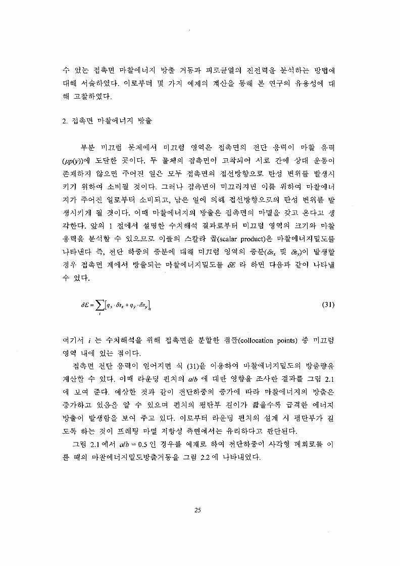
2.
1 A S 5 . ^11-^ ^^-5} ^-(scalar product)^ ^
SE
(31)
i fe- l"(collocation points)
Si
2.1
A]
2.1 4 1 ^ a/b = 0.5
nflo] 2.2
25

26

3.
1.3 ofl>H
^ collocation point)* 5>7fl «>^, Flamant
(32)
K
rX, =
5-1
m=\
5-1 ,
m=\
(34)
m
collocation point
collocation point
^ 71 ^oo
# M"B]-\ft4. ^ ,
collocation point
914. > C
((
- d)02
27

(36)
((* - md) - d)©2
rf)6>3 + 2yLx -
\ ( 3 8 )
+ ((x - ffjrf) -d)L2+ ((x - md) + d)L3}
0, = tan"1 ((x - mrf)/^), 02 = tan"1 {((x - md) - d)jy), 6>3 = tan"1 {((x - md) + d)/y},
Lx = log((x - md)2 +y2),L2= log|(x - md) - df + y1} L3 = log|(x - md) + df + y2 }.
S.5L <£#$.%<*) $& Airy ^-
I 4 ii 3.)
^el(Bueckner
-^(traction free) S ^ # ^^*>7l ^ * H 0 °1 S]£-S-
2.3
28

p(xm) or q(xm)
p(x) or q(x)
2.3. o]
A j= n A j
= JnK +K'U
(y\s')ds' +JBy. (s')k^ (y',s')ds'
(39)
(40)
, a2--fS. 1)4
vector bx-, by-7\ 5 ^
Burgers vector
SL-fS. 11)^.^4 Burgers
= x'
Kernel
l - o H G &
fe y\ J = N H ^ 7)
D 1
(39)^
q (39)
I ^ -S-^
^f^ 3.-?-=.
(40)
fe 4-8-4
:^ = A\ sin 6 + A-± cos 9 - A3 sin 20 (41)
29

$ = £, sin 2 0 + B2 cos2 0 - B3 sin20 , (42)
l 26-s\n20) (43)
9-sm29). (44)
A, ^ 5,-(i=l,2,3)fe 4
, ^ = G] cos 0 + G2 sin <9 (45)
A2 = -G3 sin <9 + G4 cos9, B2 = G3cos9 + G4sin0 (46)
(47)
G! = x^ 2/r,2 - 4(y - s)2 /rt4 + 2/r2
2 + 4(y2 + s2 )fr24
+ 32sy(y + s)2/r26}
G2={- 2(y - s)/r{2 + 4(y - sf /rf + 2(y - s)/r}
- 4<y + s)(y2 + 5sy -s2)/r$ + 32sy(y + s)3 /$ }
G3 = x{- 2/r,2 + 4(y - s)2 /r? + 2/r22
- 3s2 )
G4 = fay - s)/r? - 4(y - j)3//J4 - 2(3^ + 5s)/r22 -
s)(y2 + 34sy + 9s2 )/r24 - 32sy(y + sf / 4}
G5 = {- 2{y - s)/r,2 + 4(y - sf /rf + 2(y - s)/r?
- 4(7 + s)(y2 -6sy + s2 )/r24 - 32sy(y + s)3 /r2
6
r?
G6 = x{- 2/r,2 + 4(y - 5 ) 2 / n4 + 2/r2
2
- 4{y2 + 4sy + s2)/r24 + 32sy(y + s)2/r2
6
2
(53)
30

rl2=x2+(y-s)2,
G, ~G«1- 4 (41)^£) (44)°fl
(54)
(55)
(54)4
= rxyr = 0). t!:^, 3 (54)4 (55)5.
I f^lrf«+ f5(«)t(v,tt)rfw = /(v), ( -1<V<1) (56)-1 -1
(56)4 ^ - ^ ^° i ^ ^
^Hfloluf ^^Sfl# ^ ^ §1^- ^-f7f § 4 . ^ 1 4 Jacobi 4 ^ " ^ 4
function)* ^l-g-«H ^ H ^ ^ [29]^-S. ^ ^ ^ Si 4 .
2.3 4 £°1 5^°1 yJr^t> ^ ^ ^ 4 - B - ^ ^ ^ ^ 1 3 5UoL ^ :
§ ^ } £ S , B(u)M: 4 ^ - 4 ^°1 ^T-^lf-^4 -rrW(bounded)
31

B{u) = 5P(M) W(U) = <F{u (57)
fe(w = -1). Jacobi
v _
M/=cos(^—T^ » vy=co
(58)
(55)^
^(integration point)0lcf. ^ ^ - ^ (54)3}-
6)«fl
2V2G
(59)
(60)
(1)
32

/2£*(62)
2.4
0.0 0.2 0.4 0.6 0.8 1.0
2.4. eH:^ 371 i Si*!:
33

sit!: ^ tb# ^ inclusion
precipitate ^ ^ ^
2-5 M^^r
^ 7$J>-7\ H ^ 2.3
°lfti
0° ~ 50°
«- cfi
2.4
0.305, 0.314, 0.323, 0.378
2.3
2.5(a)
= 0.005, 0.56, 0.85, 0.99)
3-g-tt ^ f
/ > « = (63)
34

(X10"2)
-0.0.00 0.01 0.02 0.03 0.04
a I W
(a)*/
(X102)
000.00 0.01 0.02 0.03 0.04
a I W
2.5. (9=0°).
2.5(a)
K,lPm^a 3
K,
7}*]v]
fe- //w 7> ^
35

(X102)0.1
0.0
-0.4
- O 5o
!Crack
-*-" " '
Closure
0=0°
0=10°
^=30°
5=50°
2a/w (X10-2)
(X102)0.6
(X10"2)
2.6. -S- = 0.005).
= 0.005, 0.56, 0.99, 0.85
36

$14.
2.6(a)
2.5(a) ^ H ] j l ^ ^ > ] ^ g o ^ ^ ]
6(b)
^-S.^ 2 -32] 3-^(K;,)7} X]H ^ oj-
^ 4 * 1 ° 1 woV*M yBHr ^ - f l - ^ ^ ^$14. ^ S t^ " ^ 0 ! °J<H47l ^
(2)
37

l/w = 0.005
= 0.56
O-0.5
-1.0
7Rigid BodyDisplacement, A
Time
2.7.
. o)
1 H711-
2.7 o f l ^
38

2.7
43Cf.
2.7 7^o}7>
2.7
= 0.001 = 0.56 « 1 ^ ^= 0°, 10°, 30°,
2.8(a)
= 0 <a
39

(X10~3)
(X10"3)
Time
-1.0
-1.0Time
2.8.
^ ^-(at o/w = 0.001, //w = 0.56).
^ ^ A I . ^ . E l b e r
40

(X102)
(X102)
Time
(a) II w = 0.93
Time
(b) llw = 0.005
-1.0
whenp at//iv = 0.93
-1.0
2.9. l/w °\] 4 1 -
0.001, 0= 30°).
alw =
2.8(b)*l|
2.7
3.7] 7} 4 ^
41

2.9(a) ^
0.93 ^ 0.005)0)1
2.9 n e l 2.7 <fl>H£. 1"
= 0.93, H ^ 2.9(a))7|-
0.005,
nfl ^.
42

1.
3.1
3.1
10)
3.1 3.3
3.1 ^ 2)-i-
7] Sj - ^H.^4 514 A|-O]o]
3.1
LVDT(Linear Variable Differential Transformer, -L^ 3.1 £] 7)-
90° 3.1
43

PC
Fretting Wear Tester
3.1.
9:
S. % 7: LVDT, 8: I - * ,
i£^) , 10:
fe 2 3.1
3.1
2.
3715}-
44

1?R 2.5
R5
(R15
(a) (b)
3.2.
3.2 (a))4
3.2 (b))A
^ 2.5
^ 15 mm 2. ^ &
3.2 (a)
i . 7J- Type 304
15 Azm, 400
Hz
^- 30 N £fe 50 N,^: 3711 *M
30
^ 300,000
714)71
n
45

25
| 2 0
J2- 1 5
10
a<Q. 0
;;;• ;;;;;S]ip:range
0.0 0.5 1.0 1.5 2.0 2.5 3.0Number of cycles (X 105)
3.3.
3.3 ^llfe ^ # ^ ^ j ^ ^ ^ r 20 N, ?M ^ . ^ 14 Mm SL
s ] ^ ^ 300,000 S ^ t i : ^ ^ ^ f 1 ^ ^ 71 - ^
:71 ofl
3.3
7]?>(300,000 5] S]
# 400 im A
± 50
400
46
ft
£)J1
40 tun
ft^
O|«fl
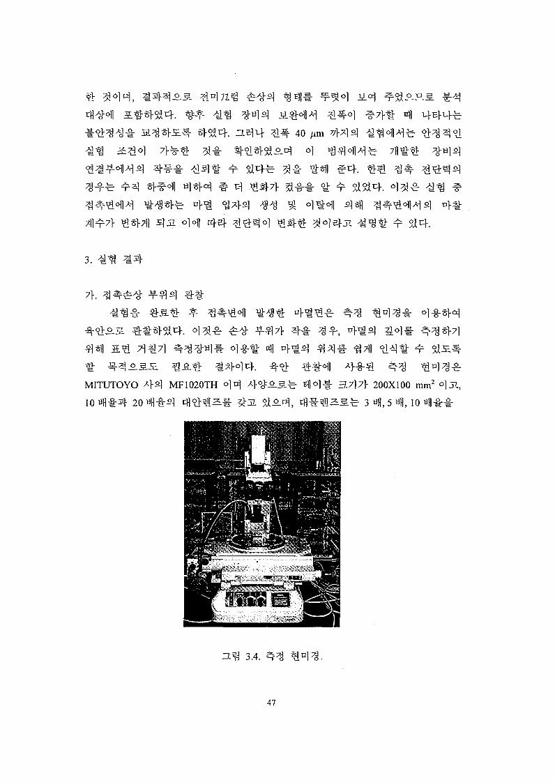
3.
MITUTOYO ^ } ^ MF1020TH ^- 3 7 ) 7 } 200X100 mm2 °}JL,
^ S S r 3 «H, 5 Hfl, 10 «!!•§:•§•
3.4. #
47

(b)
15
3.7) (a) 30 N, (b) 50 N
-S- 2.5 mm).
(a)
^ 3.6.
(b)
50 N,400
l l - (a) 2.5mm, (b) 15 mm.
200
. ^ 20°C <^] i (3 + 0.02L; L
3.4 *Hfe1 5
l 30 N
15
l - PC
3.5
50 N
3.6 (a)
3.6
2.5 mm 15 mm
400
•§••§•
CCD
48

3.6 ^ H ^. 15
2J-o.JE.3-
n>
2.5 mm o^
5>iO.H.S.[7]
stylus
^ MITUTOYO AH
. ^ ^ a . £ . ^ P profiled
^ £ f e 0.5 mm/min
stylus
fe 80 A)
3.7
5.0
3.7.
0.2 0.4 0.6 0.8Axial length (mm)
1.0
49

4. n l ^
7\. 7fliL
]o>£lJL $£4[37-39]
ZL ^-S| f-o]
t71 ^
^1 [37,39]
Cattaneo ) [ ] ,
514.
50
o] 5>Jt)-[41,42].
stylus)*
O}^- X\o\) cgTfl £ j - 2
3.7 Waterfall
Chart ^ ^ ! ^
^- itj-e* O)A> i=(|olBi7*
0.0005
^ 0.001
c V
71^717* ^
51

(l) *
^^(Fourier Transformation)*
fe 2
"&WM > ^ X-] rfl^ -f-4 ^ El (Low-pass Filter)
| A] ^V Ho
Frequency)
10Axial Direction
0 0
20
10
Transverse Direction
3.8.
30 « i ^ , 20
3.8
52

°3 ( I n v e r s e Fourier Transformation)^;
71
o]^ 4 ^ - 4 ^"^r 3!-thr(Window Function)
^ "Windowing"[43] 7]^^ ^ g ^
(64)
£ fl (^) ( ^ ) ) q 63.2%
(2) *M ^-^nf'i^-S] 3
^ y ^ yoH
53

Raw data ofthe surface
2 dimensional FFT
Determine Cutoff frequency
Low-pass filtering
2 dimensional Inverse FFT
Exponential windowing
Select datum (Fh or other)
Calculate wear volume
Graph results
rEnd
3.9.
7l| S)
A S . 0.0005 |im
y ^T "o1"^—^ 10 nm 2-1 ^-§--5.
ic Spline)-=r
MatLab®(version 5.3)[44]-§:
54

. °H 4-8-^ 3.9 4
3.12
711)
3.10
3.11
3.io
3.12 (a)°t|Ai-e x
3.12
3.10
^ . 24
3.12 <^l^i^
^- y
3.12(a)
2000
1 sfl
0.5
Axial length(mm)
150200
Transverse length(jim)
3.10.
55

0 5 10 15 20 25 30 35 40 45 50
3.11.
10 12
150100
Transverse length(jim)
(a)
10S
•8
3.12. ZT% 3.10 2] n}
50100
150200
0 Transverse length(jim)
(b)
jf:
56

(2) 4 1 JjJ-iq ?$<& *] K
3.12 (b)£] ^ - f oil ^ (64)4 ^ £ "Windowing"^
^ 3 1 ^ € 4 1 -r-^fe ^ 45.1237X10'6 mm3 4 46.4026xl0"6 mm3 A
, "Windowing" £) ^-g- <^<>fl 4 € - 4 1 T ^ ^ I * H f e 2.8% ^ £ 5 . ^ 1 He]
0.76 nm •§• T ^ ^ ^ I - 5 1 4 . -¥-3i| TJl-a- l 1 4 "Windowing"^]
7}
^- nfl "Windowing"^
Windowing" * J s | ^ ^ A * > 4 J L ^ 4 ^ ° ! 4 A ^ H-^-Zl^0!]^ "Windowing"
3.9 ^-2:).
5a* ^ $1x4. H ^ 3.13 «11 K £ N
3tl 0.76
H ^ 3.13 A
. A: a t *
3.13
3.13 4 £ £ |x>* ^«^H 4 1
^ Ra ? t ^
* 41
57

o]
Estimated regionof wear only
0 0.2 0.4 0.6 0.8 1.0 1.2 1.4
3.13.
58
2000
51 oi
• % •
3.7}2]- o}6]}
- 1 71
SEM
59

s 2 s a
(1) Johnson, K. L., 1989, Contact Mechanics, Cambridge Univ. Press.
(2) Smith, J. O. and Liu, C. K., 1953, "Stresses due to Tangential and Normal Loads on an
Elastic Solid with Application to Some Contact Problems," J. Appl. Meek, Vol. 20, pp.
157-166.
(3) McEwan E. , 1949, "Stresses in Ealstic Cylinders in Contact along a Generatrix,"
Philosophical Magazine, Vol. 40, pp. 454-460.
(4) Sackfield, A. and Hills, D. A., 1983, "Some Useful Results in the Tangentially Loaded
Hertzian Contact Problem," J. Strain Analysis, Vol. 18, No. 2, pp. 107-110.
(5) Hills, D. A. and Nowell, D., 1994, Mechanics of Fretting Fatigue, Kluwer Academic
Publishers.
(6) Kim, Hyung-Kyu and Lee, Soon-Bok, 1997, "Crack Initiation and Growth Behaviour
of Al 2024-T4 under Fretting Fatigue," Int. J. Fatigue, Vol. 19, No. 3, pp. 243-251.
(7) Ciavarella, M., Hills, D. A. and Monno, G., 1998, "The Influence of Rounded Edges
on Indentation by a Flat Punch," Proc. Instn. Mech. Engrs., Part C, Vol. 212, pp.
319-328.
(8) ^ ^ } , ol^-g-, 1996, "^-^1 ^ - g - ^ 5-ailSl * § # 2 ] 3 s h " £ i m 7 ] « 5 | fe
£ - 3 (A), ^120^, 4 131, pp. 180-188.
(9) Watrehouse, R. B., 1975, Fretting corrosion, Pergamon Press.
(10) Mindlin, R. D., 1949, "Compliance of Elastic Bodies in Contact," J. Appl. Mech., Vol.
16, pp. 259-268.
(11) Cattaneo, C, 1938, "Sul Contatto di Due Corpi Elastici: Distribuzione Locale Degli
Sforzi," Rendiconti dell' Accademia nazionale dei Lincei, Vol. 27, Sen 6, pp. 342.
(12) Hills, D. A., Nowell, D. and Sackfield, A., 1993, Mechanics of Elastic Contacts,
Butterworth-Heinemann Ltd.
(13) Bentall, R. H. and Johnson, K. L., 1968, "An Elastic Strip in Plane Rolling Contact,"
Int. J. Mech. Sci., Vol. 10, pp. 637-663.
(14) Muskhelishvili, N. I., 1958, Singular Integral Equations, Noordhoff, Leiden.
(15) Nowell, D. and Hills, D. A., 1988, "Contact Problems incorporating Elastic Layers,"
Int. J. Solids Struct, Vol. 24, No. 1, pp. 105-115.
60

(16) Private communication with Hills, D. A., 1998.
(17) Archard, J. F., 1953, "Contact and Rubbing of Flat Surfaces," J. Appl. Physic, Vol. 24,
No. 8, pp. 981-988.
(18) Iyer, S. S. and Ko, P. L., 1996, "Finite Element Modeling of Plastic Deformation,
Crack Growth and Wear Particle Formation for Sliding Wear of Power Plant
Components," Flow-Induced Vibration, PVP-Vol. 328, ASME, pp. 369-377.
(19) Kim, Hyung-Kyu, 1997, Behaviour of a Surface Oblique Crack in Fretting Fatigue, Ph.
D. Thesis, KAIST.
(20) Muskhelishvili, N. I., 1977, Some Basic Problems of Mathematical Theory of
Elasticity, Noordhoff, Leiden.
(21) Archard, J. R, 1953, "Contact and Rubbing of Flat Surfaces," J. Appl. Physic, Vol. 24,
No. 8, pp. 981-988.
(22) Mindlin, R. D. et al, 1982, "Effect of an oscillating tangential force on the contact
surfaces on elastic spheres," Proc. Is' US National Congress of Applied Mechanics, pp.
203, New York: ASME.
(23) Johnson, K. L., 1961, "Energy Dissipation at Spherical Surfaces in Contact
Transmitting Oscillating Forces," J. Mech. Eng. Sci., Vol. 3, pp. 362.
(24) 3*lfl-, 1999, " f ^ W ^ H € #&*W 3-8-*l eJ-Sr^SH ^t t ^ #
-5-^," tfltlrTMl^slfe^A^, *fl23 , aflSSl, pp. 801-813.
(25) Nowell, D. and Hills, D. A., 1987, "Open Cracks At or Near Free Edges," J. Strain
Analysis, Vol. 22, No. 3, pp. 177-185.
(26) Kim, H. -K. and Lee, S. -B., 1996, "Stress Intensity Factors of an Edge Crack
subjected to Normal and Shear Tractions," Theo. Appl. Fract. Mech, Vol. 25, No. 2, pp.
147-154.
(27) Dunders, J. and Sendeckyj, G.P., 1965, "Behavior of an Edge Dislocation near a
Bimetallic Interface," J. Appl. Physics, Vol. 36, pp. 3353-3354.
(28) Bueckner, H. R, 1958, "The Propagation of Cracks and the Energy of Elastic
Deformation," J. Appl. Mech., Vol. 80, pp. 1225-1230.
(29) Erdogan, F. et al., 1973, Methods of Analysis and Solutions of Crack Problems,
Mechanics of Fracture 1, G.C. Sih ed., Chapter 7, Noordhoff International Publishing,
Leiden.
(30) Krenk, S., 1975, "On the Use of Interpolation Polynomial for Solutions of Singular
61

Integral Equations," Quarterly Applied Mathematics, Vol. 32, pp. 479-484.
(31) Suh, N.P., 1977, "An Overview of the Delamination Theory of Wear," Wear, Vol. 44,
pp. 1-16.
(32) Suh, N.P., et ah, 1974, "Further Investigation of the Delamination Theory of Wear," J.
Lubr. Tech., Vol. 96, pp. 631-637.
(33) ^ W £| 3 Si, 1998, " ^ ^ 4^11^*1 W>fl « #*1 ^ A o^ <£*$,>•^tt7l^l*l-5j %•%*]%• 9$^7\}n^rj\n fe^], pp. 169-174.
(34) Kim, H. -K. and Lee, S. -B., 1996, "Stress Intensity Factors of an Edge Crack
subjected to Normal and Shear Tractions," Theo. Appl. Fract. Mech, Vol. 25, No. 2, pp.
147-154.
(35) Elber, W., 1970, "Fatigue Crack Closure under Cyclic Tension," Eng. Fract. Mech.,
Vol. 2, pp. 37-45.
(36) 3 1 ! T ? £] 5S1, H e U ^ P r ^ ^ ^ 1 / l i t , KAERI/TR-1570/2000,
(37) S. Fouvry, P. Kapsa and L. Vincent, Quantification of fretting damage, Wear, Vol. 200,
pp. 186-205, 1996.
(38) P. De Baets, K. Strijckmans and A.P. van Peteghem, Characterization of the fretting
wear of unlubricated steel surfaces based on the comparison of wear results obtained
by different methods, Wear, Vol. 208, pp. 169-176, 1997.
(39) M. Kalin and J. Vizintin, Use of equations for wear volume determination in fretting
experiments, Wear, Vol. 237, pp. 39-48,2000.
(40) K.H. Cho, T.H. Kim and S.S. Kim, Fretting wear characteristics of zircaloy-4 tube,
Wear, Vol.219, pp.3-7, 1998.
(41) 3 # s h ^ ^ > ^-8-^. ^ W ^ ^ ^ ^ U - i -^ ^ • • g - % ^ - ^ ^282) ^7fl*}-^rfl2l,pp. 300-305, 1998.
(42) ^ # * > , ^ Q , £ - 8 - ^ , ^ ^ 1 ^ W^-§r ol-g-^1- v}^
5\ fe^-^, ^116^1 42$., pp.33-137, 2000.
(43) D.J. Ewins, Modal Testing: Theory and Practice, pp.121, Research Studies Press,
Great Britain, 1984.
(44) Math Works Inc., User's Manual for MatLab® V5.3 Rl 1, U.S.A., 1999.
62

Square Punchy tfl«

BIBLIOGRAPHIC INFORMATION SHEETPerforming Org.
Report No.Sponsoring Org.
Report No.Standard Report No. INIS Subject Code
KAERI/RR-2078/2000
Title/Subtitle Development of Contact Failure Analysis Technology-F i r s t Year(2000) Report-
Project Managerand Department
Kim, Hyung-Kyu (Fuel Manufacturing Technology DevelopmentTeam)
Researcher andDepartment
Yoon, Kyung-Ho; Kang, Heung-Seok; Song, Kee-Nam (FueljManufacturing Technology Development Team) j
PublicationPlace
Taejon Publisher KAERIPublication
Date2001. 1.
Page p 62 111. & Tab. Yes( V ), No ( ) Size 26 Cm.
Note
Classified Open( V ), Restricted(_ Class Document
Report Type Research Report
Sponsoring Org. Contract No.
Abstract(15-20 Lines)
Contact tractions are affected by the geometry of contacting bodies. In thepresent research, square punch, wedge and cylinders are considered as the geometry.Among the geometry, a square punch with rounded corners is basically used. Normaltraction profile is obtained in the case of the rounded punch, and shear tractions areivaluated under the partial slip regime by using the influence function method.
Multiplication of the shear traction and slip displacement in the slip region of thecontact provides the friction energy dissipation from the contact. Since the trace of theshear force influences the amount of the dissipated energy, a desirable trace of theshear force may be supposed to reduce the energy dissipation. Internal stresses are:valuated from the contact normal and shear tractions, which are to be used for
calculating the stress intensity factors of a surface breaking crack emanated from thecontact surface. The stress intensity factors, K\ and Kn, are investigated during thecyclic shear. It is found that a period of crack opening exists during a shear cycle,which is effective for crack growing. So, to reduce the period can be a method forrestraining the cracking failure. On the other hand, there can exist a desirable shape ofthe contacting body, which can restrain the cracking failure. In the experiment, frettingwear tester is used with the specially designed specimen. Wear of the contact surfaceare observed in detail, which shows typical shape following the partial and gross slipregimes. An algorithm for evaluating the wear volume is newly developed using thesignal processing technique and the Fast Fourier Transform (FFT).
Subject Keywords(About 10 words)
Contact Failure, Contact Tractions, Punch with RoundedCorners, Partial Slip, Influence Function Method, Friction Energy jDissipation, Stress Intensity Factor, Cyclic Shear, Fretting Wear|Tester, Wear Volume I