Embed Size (px)
Citation preview
- 1012 -
ANALYTICAL MODELLING
of
SBEAR CONNECTED MASONRY CAVITY WALLS
by
M. Rashwan. P.E.;
Director of Research P.M.R.I. Edmonton, Alberta, Canada TSS lG7
Abstract
Cavity walls constructed of eonerete bloek baekup and elay brick veneer are beeoming very popular eonstruetion systems beeause of their arehiteetural flexibilities and favorable struetural qualities.
Reeently, a stiff metal eonneetor has been developed which has the eapabilities of ereating a eomposite aetion between both the baekup wall and veneer and henee reduees the magnitudes of the transferred loads to the baekup system and in turn results in thinner and more economical baekup walls. Extensive testing program eondueted at the University of Alberta, Edmonton, Canada, has verified the struetural eoneept on whieh the system is based (i.e. the eomposite aetion eoneept). In order to analyze the system, a simulated eonfiguration has been developed which allowed the system to be analyzed as a planner frame.
This paper presents the process of analyzing the system whieh led to the development of design load/defleetion tables. These tables would enable the struetural designers and architects to seleet the most eeonomical bloek baekup/veneer system whieh satisfies both the Code requirements and the applied loads.
- 1013 -
INTRODUCTION
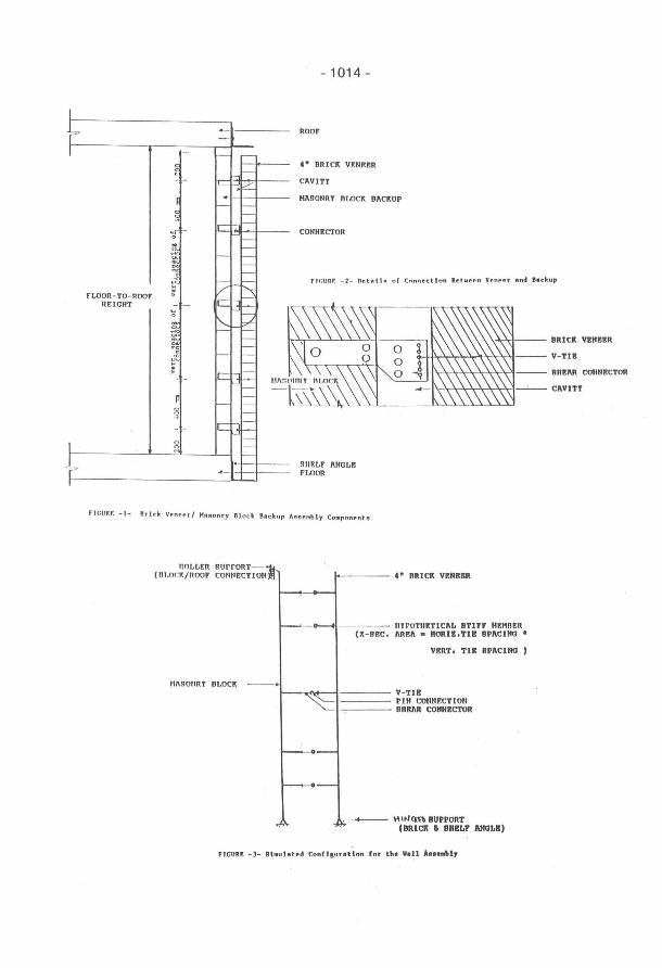
The work discussed herein has been initiated mainly for the purpose of developing a "Design Aid" that assists the structural engineers and architects in their designs of shear connected cavity walls. In developing such means, a wall assembly consists of: a concrete block backup, clay brick veneer and a shear connecting device has been simulated for computorized structural analysis purpose (Figure 1). The simulated wall assembly has been subjected to different wind pressures, suctions as well as the dead load imposed by both blocks and bricks self weights. Nine different heights (floor-to roof) have been assigned to the wall assemblies. Planner frame analysis has been used to determine the maximum normal stresses in each component due to applied loads. Based on the data accumulated for a large number of cases, simplified relationships have been developed to approximately describe the behavior of the main components of the assembly. These relationships have considered the changes in the main variables in the problem. Combining the data accumulated from the computer analysis with those from the simulated relationships, cavity walls design tables have been prepared. These tables would enable the designer/architect to select the most economical wall assembly that withstands a wide range of applied wind loads. The following sections present the parameters included in the problem and the process of developing the different relationships that were necessary to develop the load/deflection tables.
I. Parameters Included in the Structural System:
- The wall assembly subject to stress analysis regardless of the height (floor-to-roof), block width and cavity width is as shown in Figure 1.
- Details of connection between the brick veneer and backup wall, regardless of cavity width is as shown in Figure 2.
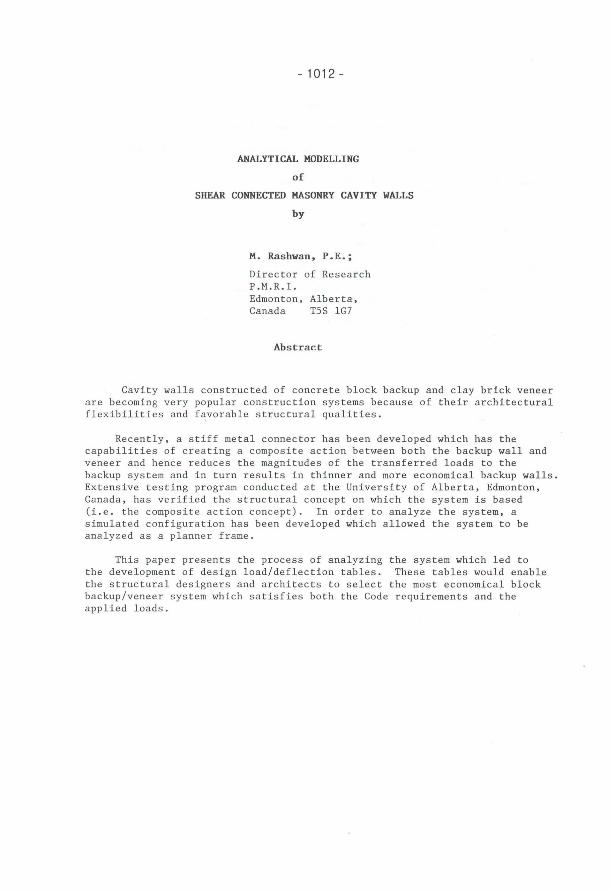
- The simulated configuration for the wall assembly for purpose of stress analysis (as a planner frame) is as shown in Figure 3.
- The following parameters are considered constants: *The width of the brick veneer : 90 mm *Cross sectional area of shear connectors :120 mm 2
*Cross sectional area of V-tie (wire) : 35.5 mm 2
*Spacing of connectors - Horizontal :800 mm Vertical
*200 and 400 mm respectively top and bottom followed by equal spacings of 600 mm (for the rest of the height).
- The following parameters are considered variables: *Floor-to-roof height: Nine different heights have been considered
for analysis, namely: 2400, 3000, 3600, 4200, 4800, 5400, 6000, 7200, and 8400 mm.
*Masonry block width: Five standard sizes have been considered namely: 90, 140, 190, 240 and 290 mm.
*Reinforcement Options: Four options have been considered namely, plain (no reinforcement), 1#15 @ 1600 mm, 1#15 @ 800 mm and 11115 @ 400 mm.
*Cavity Width: Three cavity widths have been considered, namely, 50 mm, 75 mm and 100 mm.
*Wind Load: Two values have been considered, namely: 0.6 kPa and 1.0 kPa (or 1.2 kPa in some cases).
L r
I
l=
---
. - -
-~,
r-'6- -.. t -
" -;/ FLOOR - TO- ROOF :
IIEIGHT ir- '-
f ~
c--" . > Ic -P o r--o ., - - Ic o o
-
--
~
r--r--r--c--c--c--c--c--
~ f--p r--c--c--c--c--c--f-- IIlIS t t- --c--c----I----r--r--r--.-- t--
- 1014 -
Roor
4" ORICI{ VENEER
CAVITJ
HASONRJ BLOCK BACIIUP
CONNECTOR
f 1f:IIIH: - 2- n(! t n l '1'1 o f Cnnnec:t l 0" fte twtt!n ~ ~ " ee r a.,d e.c ltup
SIIELF ANGLE FLOOR
\-'I:\t--- BRICII VENBER
COIINECTOR
Fl GU RF. - 1- Rrlck Ve nepr l HA80nry Bloc lt BII c ku p AS8e mbl y COlllponente
nOLLEn GUrrOnT(DLOCK/noOF COIINECTION 4" BRI!=I{ VEIIBBR
IIlrOTIIITICAL 8Tlrr IIEHnER (X - BEC. AnEA • II0Rlll.TIS BPIICIHII •
VERT. TIS 8PIICIHII )
~--~~~i----- V- TI!
•
r I li COIINECT I OH ~--- DUBlin CONlltlCTOR
_ ~,rJ<n\ BUPPORT
(BRlCII • SUtlLr ANIILtI)
- 1015 -
11. The AnaIysis and Data AccumuIation:
PIanner frame analysis were performed in order to accumuIate stress values, for different components of the system, according to the different loading conditions.
It should be noted that two sets of analysis were conducted in order to best describe the behavior of the assembly. These are: A) For uncracked backup wall: where the aIlowable tensile stress in
the concrete bIock governs the designo B) For cracked backup wall: where the reinforcement begin to
effectively resist the tensiIe forces introduced by the lateral wind Ioads.
The following sections present the assumptions used for each set of anaIysis as well as the simulation process that led to the development of the various relationships used to calculate the data presented in the Load/ Deflection tables.
(A) Uncracked Section Analysis: Values of mortar bedded area, moment of inertia, section modular, limiting stresses and modulus of elasticity were calculated according to the Canadian Code (5304-84).
After analyzing the cases for 90 mm and 140 mm block sizes for their corresponding heights, it became evident that proportional relationships exist among some of the variables in the problem. These relationships can be expressed mathematically as follows:
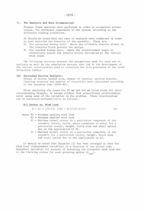
A-I Stress vs. Wind Load
W
where Wl W2 fl
f2
Wl + «f-fl) «W2 - Wl)/(f2-fl»)
Minimum applied wind load Maximum applied wind load
(1)
Maximum normal stress in a particular component of the assembly (block, brick, shear connector or wire) for a particular cavity, height, block size and steel option due to the application of Wl. Maximum normal stress in a particular component of the assembly for a particular cavity, height, block size and steel option due to the application of W2.
It should be noted that Equation (1) has been arranged so that the wind Ioad (independent variables) is a function of the stress (the dependent variable) for purpose of determing the allowable wind load due to the limiting stress for each grouting option (f
lim).
- 1016 -
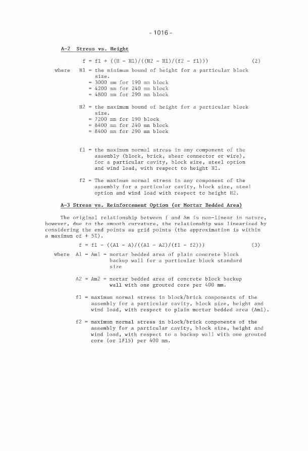
A-2 Stress vs. Height
f fl+ «H - Hl)/«H2 - Hl)/(f2 - fl))) (2)
where Hl the minimum bound of height for a particular block size. 3000 mm for 190 mm block 4200 mm for 240 mm block 4800 mm for 290 mm block
H2 the maximum bound of height for a particular block size. 7200 mm for 190 block 8400 mm for 240 mm block 8400 mm for 290 mm block
fl the maximum normal stress in any component of the assembly (block, brick, shear connector or wire), for a particular cavity, block size, steel option and wind load, with respect to height Hl.
f2 The maximum normal stress in any component of the assembly for a particular cavity, block size, steel option and wind load with respect to height H2.
A-3 Stress vs. Reinforcement Option (or Mortar Bedded Area)
The original relationship between f and Am is non-linear in nature, however, due to the smooth curvature, the relationship was linearized by considering the end points as grid points (the approximation is within a maximum of + 5%).
where
f fl- «Al - A)/«Al - A2)/(fl - f2))) (3)
Al Aml = mortar bedded area of plain concrete block backup wall for a particular block standard size
A2 Am2 mortar bedded area of concrete block backup wall with one grouted core per 400 mm.
fl maximum normal stress in block/brick components of the assembly for a particular cavity, block size, height and wind load, with respect to plain mortar bedded area (Aml).
f2 maximum normal stress in block/brick components of the assembly for a particular cavity, block size, height and wind load, with respect to a backup wall with one grouted core (or 1#15) per 400 mm.
- 1017 -
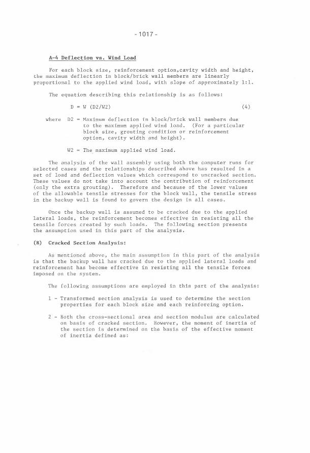
A-4 Deflection vs. Wind Load
For each block size, reinforcement option,cavity width and height, the maximum deflection in block/brick wall members are linearly proportional to the applied wind load, with slope of approximately 1:1.
The equation describing this relationship is as follows :
D
where D2
W (D2/W2) (4)
Maximum deflection in block/brick wall members due to the maximum applied wind load. (For a particular block size, grouting condition or reinforcement option, cavity width and height).
W2 ~ The. maximum applied wind load.
The analysis of the wall assembly using both the computer runs for selected cases and the relationships described above has resulted in a set of load and deflection values which correspond to uncracked section. These values do not take into account the contribution of reinforcement (only the extra grouting). Therefore and because of the lower values of the allowable tensile stresses for the block wall, the tensile stress in the backup wall is found to govern the design in alI cases.
Once the backup wall is assumed to be cracked due to the applied lateral loads, the reinforcement becomes effective in resisting alI the tensile forces created by such loads. The following section presents the assumption used in this part of the analysis.
(B) Cracked Section Analysis:
As mentioned above, the main assumption in this part of the analysis is that the backup wall has cracked due to the applied lateral loads and reinforcement has become effective in resisting alI the tensile forces imposed on the system.
The following assumptions are employed in this part of the analysis:
1 - Transformed section analysis is used to determine the section properties for each block size and each reinforcing option.
2 - Both the cross - sectional area and section modulus are calculated on basis of cracked section. However, the moment of inertia of the section is determined on the basis of the effective moment of inertia defined as:
- 1018 -
I eff (I cr + I un)/2
where I eff effective moment of inertia I cr cracked moment of inertia I un uncracked moment of inertia
It should be noted that the above value is taken from the Code (S304-M84) and adapted in this analysis because of the following reason. since the wall will not crack over the full height but only where the maximum stresses occur, a high penalty (i.e. higher stresses and deflection and lower allowable loads) would be imposed on the wall if the cracked moment of inertia is used instead.
It should be noted that the same relations developed earlier for the uncracked section were adapted lor the cracked section although non-linearity exists for Relationship -1-. From simplifying purposes the relationship was assumed linear since the curvature values were insignificant.
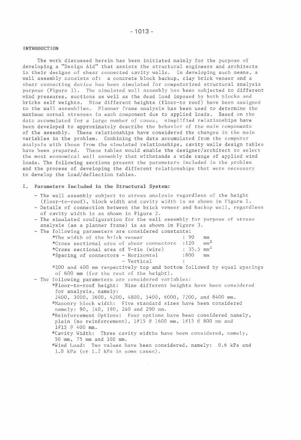
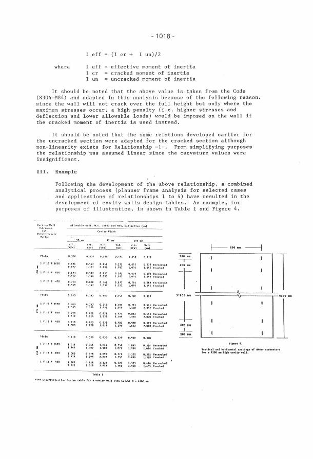
111. Example
Following the development of the above relationship, a combined analytical process (planner frame analysis for selected cases and applications of relationships 1 to 4) have resulted in the dev e lopment of cavity walls design tables. An example, for purposes of illustration, is shown in Table 1 and Figure 4.
--~~-----_. ---- ------ - ---~ .• (. - "p \1,,11 All o ....... '. Unt r . V.L. (lr., .nd H,1 •. D.fhct",,, (_) T"h ' n~".
c ... !!, VUlh .~tnf .. ~cr .. ' .. t
"pIlo" __ --..1~ _ ____ ..!!_- Igo _
\1.1 .• Dtr. V.L ner. II.l. D,,, Il_r:,,~~r_._) __ ~) (to,., (-)
n .HO 0.50' n. 5~O 0.'1'1 0.5'" 0.41'
, , J5' HOO 0 .59 ' 0.561 O. '~1 0.511 0.U7 0 .H2 0 , 11111 1.1" n.11I11 I .nu 1.001 1.148
~ t' 15 (I .0<1 0 . 61] 0.592 D.U) 0.5111 0 . 611 0.590 n._H 1 . 1U n.,.) 1.141 1.0H 1.141 , , n, '" 0 . 111 0.611 0 , '(,1 0 .6 11 0.1'1 0.618
1.1" l . nH 1. 152 1.0'" 1.141
rI ~ I .. O.1l) O.6~O 0.)54 0.710 0 , 1(,'
,. n (li 11\00 0 . 100 0 . ]6) 0 . 14) 0 . )87 0.791 0 .411 1.)" 2 .I H 1.41! 1 . 0" I.UI 2 . 041
~ ,. '" .... 0.190 0.411 0.111 0 . 421 O . ." O. U) 1.114 1.,,, 1 . 10~ LHA 1 .010
I ' U, ... 0 . 910 (LU) O.UI o .• ., 0."1 O.SI' I .'OA 1.911 1.~14 1 . 106 I.~U f.021
PI.o,I .. 0.'10 n.lU 0."0 o.,,, 0.'40 o.no ,. u , IfliOO 1 .016 O.", 1.0U 0 . )54 1.0'1 o.),.
I.''''' 1.0fl' 1."" 1.071 l.'U I. OU
~ " 15' ... 1.080 0.)1' 1.0'0 O.Hl 1.102 O.ln f.'" 1.2911 !.U! 1 .150 2.,,, 1.1"
I' n" lO' LU) 0.414 1.'11 0 . 4U 1.)) 0.416 1.fliH 1.)1' f.fl51 · 1 . 'fll f."1 1.40'
T",h I
"In<l ln.",n,f1ectlon .'.'.-" t.hh foI' • cnlt, v.lI vlth he""t •• unn _
200 _
--,-Uncu(hj 400 _
Cud .• "
l Uncuch' Cr.c",".
Uncuch4 Crachd
5'100 ""
Uncrach'
-L r:uch'
Ullene ..... "lIIehol
U"lI:rtelt •• "nelt •• UO'"
---L-200 _
U .. enclt •• Cuc .....
tlllenelt •• CU( ....
O .. lI:uelt •• Cud ••
I
J-IOO- ---I
'utlt.1 111' horl .. , .. t.l .,.eI .... Ir ...... e_d .... , .... UOO _ lIl ... enlt, "11.
- 1019 -
IV. Conclusions and Recommendations:
The above analytical process has resulted in the development of allowable load/deflection tables for the conditions and assumptions presented earlier. The main objective of developing such tables is to assist the structural engineer/architect in selecting the most appropriate and economical wall assembly for selected applied loads. Certain limitations apply for the use of these tables. These limitations are briefly discussed as follows:
1. Height Limitations: The tables are developed for selected heights namely 2400, 3000, 3600, 4200, 4800, 5400, 6000, 7200, and 8400 mm. The allowable load/deflection values presented in the tables are those for each specific height.
2. Cavity Widths: Three cavity widths have been used for these tables. Those values of the cavity width namely 50, 75 and 100 mm respectively were selected on the basis of the commercial insulation sheets thickness available and commonly used for constructing such walls. From the analysis data it was evident that no apparent mathematical relationship exists between the cavity width and the stress and/or allowable loads. However, it was noticed that the stresses decrease in the blocks, bricks and V-tie with increasing cavity and they increase with increasing cavity in the shear connectors. As a result the allowable wind "loads are expected to increase with increasing cavity width. (It is recommended that specific analysis is conducted in case of different cavity width is given since no direct interpolation is available).
3. Connectors Spacings: Only one spacing namely 800 mm horizontally by 600 mm vertically is adopted in the analysis. This spacing arrangement was selected as the most economical arrangement for the connectors for straight cavity walls with no openings. However, if large and frequent openings exist in the wall, spacings, both vertical and horizontal may be reduced and specific analysis should be conducted.
4. Veneer Clay Brick Width: 90 mm clay brick was used as the veneer wall for this analysis. Again, this standard size has been selected based on the common practice of constructing such types of walls.
References:
1. C. S .A. Standard, CAN3-S304-M84 "Masonry Design for Buildings"
2. J. Glanville and M. Hatzinikolas "Engineered Masonry Design," First Edition, Winston House Publications, Winnipeg, Manitoba, Canada.
3. P. Papanikolas, "Shear Connected Cavity Walls" M.Sc., Thesis, University of Alberta, Edmonton, Alberta, 1990.