Embed Size (px)
Citation preview
10. Selection Criteria for the Rocket Engine System Design and Overview on the Principles Relevant to the Use of Nuclear Power Sources in Outer Space
Team 2
Outline
1. Introduction 1.1 Selection Options and Criteria
1.2 The Best Viable Propulsion Options 1.3 A Little History On Nuclear Space Propulsion
2. Nuclear Propulsion Concepts 2.1 Nuclear Electric Propulsion
2.1.1 Variable Specific Impulse Magnetoplasma Rocket Engine (NEP) 2.1.2 DC Electron- Bombardment Rocket Engine Design 2.1.3 Pulsed Inductive Thruster 2.1.4 Pulsed Plasma Thruster
2.2 Nuclear Thermal Propulsion (Fission) 2.2.1 Solid Core (NERVA)
2.2.2 Liquid Core 2.2.3 Gas Core 2.3 Fusion/Antimatter Propulsion 2.3.1 Inertial Confinement (VISTA) 2.3.2 Magnetic Confinement Fusion 2.3.3 Antimatter-Catalyzed Micro-Fission/Fusion 2.3.4 Antimatter Annihilation 3. Our Analysis and Calculations 3.1 NERVA Analysis
3.2 Sample Calculations 3.3 MATLAB Code 3.3.1 Code for Earth to Mars Transfer 3.3.2 Code for Mars to Earth Transfer 3.4 Pulsed Inductive Thruster Analysis 3.4.1 Earth to Mars Transfer (from GEO) 3.4.2 Mars to Earth Transfer 3.4.3 Propulsion Mass Analysis 3.5 Nuclear Electric Power Generation 4. Cost Analysis
4.1 Components 4.1.1 Mission Support 4.1.2 Space Lift
2
4.1.3 Vehicle Components 5. Recommendations 6. Sources
ROCKET ENGINE SYSTEM DESIGN
ABSTRACT
Why nuclear space propulsion? Because of its high performance potential, nuclear
space propulsion could be utilized for manned missions and cargo transport to the moon or Mars, unmanned explorations of the outer planets, and earth orbit transfers of satellites. High performance space nuclear reactors for power and/or propulsion present a unique and challenging set of engineering requirements. Combining the most efficient requirements of a space vehicle is imperative because we not only want to enhance our fullest range of power and capability, but also minimize waste, unnecessary space, and the life risk of our astronauts. Thus, we must examine and understand the best factors that contribute to nuclear rocket performance for thrusting the human race into the next generation of exploratory space missions.
1. INTRODUCTION
Work is currently being undertaken to make the mission to Mars the next “giant
leap for mankind”. For this amazing dream to happen, we must first consider the most efficient way possible to get astronauts to Mars. Nuclear propulsion is the most attractive option. However, there are many different nuclear propulsion options as well as other propulsion options that must be considered. Not only that but how should our selection criteria be based? The next few paragraphs entertain this question as well as add what we feel as the best viable options as well as a little history of nuclear propulsion. 1.1 Selection Criteria for Rocket Engine System Design
Propulsion options include chemical, nuclear thermal, electric, and hybrid NEP/NTP propulsion concepts. The selection criteria when looking into a rocket engine system design are that of specific impulse, thrust, weight, shielding, material, cost, reliability, and fuel type. 1.2 The Best Viable Propulsion Options NASA designers have encompassed nuclear power technologies in propelling spacecraft and piloted space systems into orbit. The two primary options are Nuclear Electric Propulsion (NEP) and Nuclear Thermal Propulsion (NTP). In general, nuclear electric propulsion system consists of the arcjet concept, electric ion thrusters, or magnetoplasmadynamic thrusters powered by a nuclear reactor. On the other hand,
3
nuclear thermal propulsion system features a nuclear reactor that heats a “propellant” (a working fluid of hydrogen), and the hot, expanding propellant forces through the reactor with the aid of a turbo pump subsystem. Specifically, NTP systems consist of fission or fusion concepts as well as antimatter. 1.3 A Little History on Nuclear Space Propulsion In the 1960’s, NASA had continued the long-range flight program originally proposed by the Air Force to develop a nuclear-propelled upper stage for a rocket. NASA pursued the prospect of distant manned planetary exploration, which depended on more efficient thrust per pound in fuel propulsion. Advantages of NEP and NTP systems over conventional chemical propulsion methods include reduced travel times and/or reduced masses for science and human exploration missions. NASA engineers experienced failures during numerous initial testings, primarily due to the intense radiation density and temperatures from the nuclear source upon the existing rocket components. Radiation corrosion prematurely deteriorated the materials. Finally, in December 1967 the modified nuclear reactor named NRX-A6 ran successfully for one hour at full power, paving for improvements in long-range flight duration and refined reactor fuel elements that reduced radiation control in half. During this period, research and implementation of radioisotope thermoelectric generators in the SNAP program progressed. The possibility of expeditions to Mars spurs applications of improved NEP and NTP-propelled spacecraft. Interplanetary travel will be a feasible extension towards new, unexplored frontiers. During 1969 and 1970, concepts on nuclear dependence for proposed manned Mars missions were actively established. Through out the years, NASA anticipated eventual departures from Earth on nuclear powered spacecraft destined to reach nearby planets, like Mars. Along with conventional fission reactors, the process of fusion for interstellar flight propulsion was studied as early as 1966 by Dwain F. Spencer of the Jet Propulsion Laboratory. Research on controlled nuclear fusion was at an early stage and numerous challenges (mechanical and financial) still exist now. Space Mission Analysis For any space mission, there are a couple basic questions that must be considered while researching this project. First, what is the total trip time? We need to know the trip time because we need to know how much fuel we need as well as other supplies for the mission. Second, what is the mass of the payload we want to send there (and bring back)? The mass affects the overall mission because the more mass we have the more thrust and power we will need.
2. NUCLEAR PROPULSION CONCEPTS
The rocket engine design is like the heart of a space vehicle. It sets the groundwork for the space vehicle design as well as gets the vehicle off the ground. For this first part, we will present the different schematics of rocket engine design each NEP, NTP, and antimatter options. The key things to keep in mind here are that a rocket engine should
4
meet the NASA requirements. These requirements being that it should be able to withstand 500 to 1000 days in space and to carry 80 tons of cargo.
2.1 Nuclear Electric Propulsion
2.1.1 Variable Specific Impulse Magnetoplasma Rocket Engine (Figure on next page)
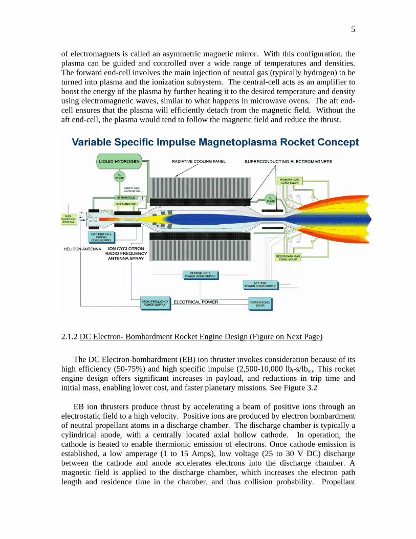
The advanced Space Propulsion Laboratory is developing a new type of rocket technology, the Variable Specific Impulse Magnetoplasma Rocket (VASIMR). See Figure 3.1. This plasma rocket drive is not powered by conventional chemical reactions as today’s rockets are, but by electrical energy that heats the propellant. The propellant is a plasma that reaches extreme temperatures, up to 50,000 degrees Celsius and above. Some scientists call this the fourth state of matter. This new type of technology could dramatically shorten human transit times between planets (about 3 months to Mars). Not only will planetary missions be fast, but also the plasma drive will propel robotic cargo missions with very large payloads (more than 100 tons to Mars). Trip times and payloads are major concerns when using conventional rockets. Basically, the VASIMR works in five steps. First, an injector feeds hydrogen or helium gas into quartz tubing. Second, a Helicon Antenna ionizes the gas. Third, Magnetic Coils generate a field that confines the ionized gas in a “mirror”. Fourth, two Icrh Antennas heat the gas to incredibly high temperatures from fifty thousand to a million degrees Kelvin. Finally, a Vacuum Chamber captures the hot gas as it escapes the magnetic confinement, which in turn would propel a vehicle. The first step to understanding how the VASIMR operates is learning about plasma. A plasma state can be achieved when a substance, in its gaseous state, is heated to very high temperatures. At these temperatures, electrons are stripped, or lost, from the neutral atoms. The result is electrons, which hold a negative charge, and ionized atoms, which hold a positive charge. These mix together to make an electrically neutral “soup” of charged particles that is plasma. Plasma is a very common occurrence in nature. In fact, ninety-nine percent of the universe is in some form of a plasma state, including lightning, very hot flames, nebulas, the sun and other stars. No known material can contain plasma at the extreme temperature required of the VASIMR. Fortunately, plasmas can be partially contained by a magnetic field. A magnetic field is a force field around a conductor that results from the flow of electrical current. Charged particles in a magnetic field move in spiral orbits around and along the lines of force. They are contained in appropriately shaped “magnetic bottles.” A unique feature of the VASIMR is its capability to vary or “modulate” the plasma exhaust while maintaining maximum power. This technique is similar to the function of the transmission in a conventional automobile. Two parameters are varied during a typical operation: thrust and the velocity of the particles leaving at the rocket exhaust. The latter is called the specific impulse. As the ship moves away from a planet’s gravity, the thrust is reduced and the specific impulse increases. The trust is raised and the specific impulse drops as the ship slows down to enter and orbit about its destination planet. The VASIMR system consists of three major magnetic cells, denoted as “forward,” “central,” and “aft.” This particular configuration
5
of electromagnets is called an asymmetric magnetic mirror. With this configuration, the plasma can be guided and controlled over a wide range of temperatures and densities. The forward end-cell involves the main injection of neutral gas (typically hydrogen) to be turned into plasma and the ionization subsystem. The central-cell acts as an amplifier to boost the energy of the plasma by further heating it to the desired temperature and density using electromagnetic waves, similar to what happens in microwave ovens. The aft end-cell ensures that the plasma will efficiently detach from the magnetic field. Without the aft end-cell, the plasma would tend to follow the magnetic field and reduce the thrust.
2.1.2 DC Electron- Bombardment Rocket Engine Design (Figure on Next Page)
The DC Electron-bombardment (EB) ion thruster invokes consideration because of its
high efficiency (50-75%) and high specific impulse (2,500-10,000 lbf-s/lbm). This rocket engine design offers significant increases in payload, and reductions in trip time and initial mass, enabling lower cost, and faster planetary missions. See Figure 3.2
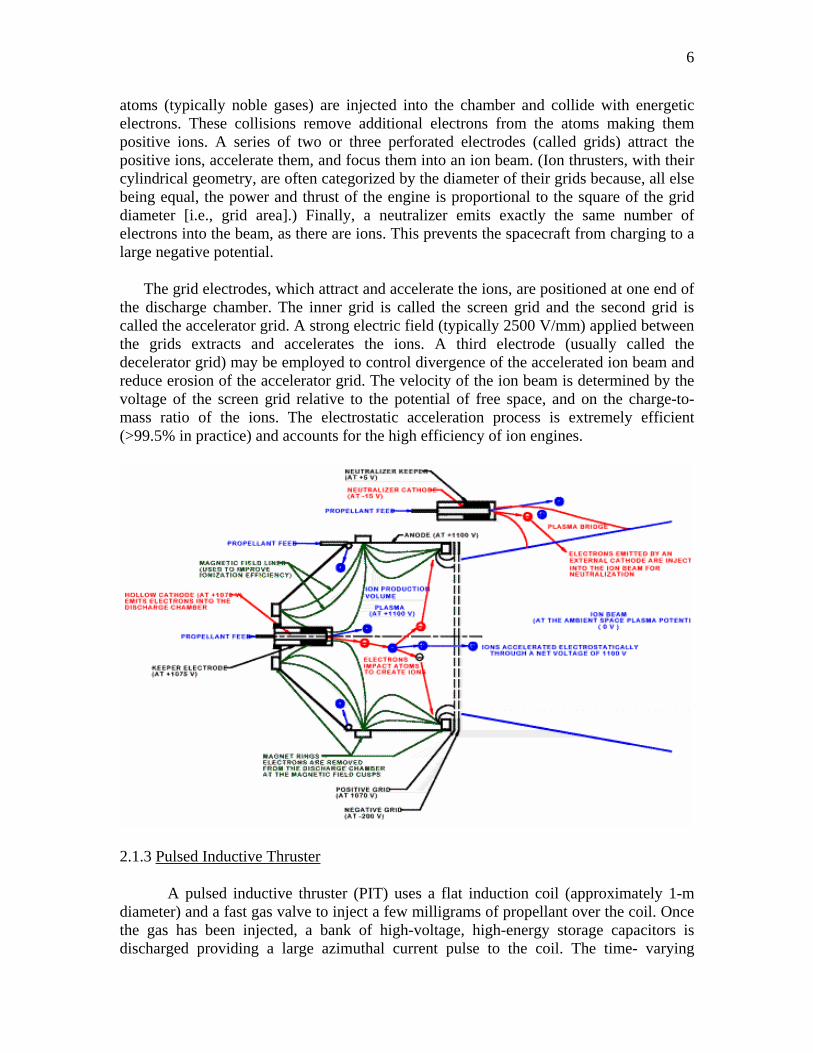
EB ion thrusters produce thrust by accelerating a beam of positive ions through an electrostatic field to a high velocity. Positive ions are produced by electron bombardment of neutral propellant atoms in a discharge chamber. The discharge chamber is typically a cylindrical anode, with a centrally located axial hollow cathode. In operation, the cathode is heated to enable thermionic emission of electrons. Once cathode emission is established, a low amperage (1 to 15 Amps), low voltage (25 to 30 V DC) discharge between the cathode and anode accelerates electrons into the discharge chamber. A magnetic field is applied to the discharge chamber, which increases the electron path length and residence time in the chamber, and thus collision probability. Propellant
6
atoms (typically noble gases) are injected into the chamber and collide with energetic electrons. These collisions remove additional electrons from the atoms making them positive ions. A series of two or three perforated electrodes (called grids) attract the positive ions, accelerate them, and focus them into an ion beam. (Ion thrusters, with their cylindrical geometry, are often categorized by the diameter of their grids because, all else being equal, the power and thrust of the engine is proportional to the square of the grid diameter [i.e., grid area].) Finally, a neutralizer emits exactly the same number of electrons into the beam, as there are ions. This prevents the spacecraft from charging to a large negative potential.
The grid electrodes, which attract and accelerate the ions, are positioned at one end of the discharge chamber. The inner grid is called the screen grid and the second grid is called the accelerator grid. A strong electric field (typically 2500 V/mm) applied between the grids extracts and accelerates the ions. A third electrode (usually called the decelerator grid) may be employed to control divergence of the accelerated ion beam and reduce erosion of the accelerator grid. The velocity of the ion beam is determined by the voltage of the screen grid relative to the potential of free space, and on the charge-to-mass ratio of the ions. The electrostatic acceleration process is extremely efficient (>99.5% in practice) and accounts for the high efficiency of ion engines.
2.1.3 Pulsed Inductive Thruster
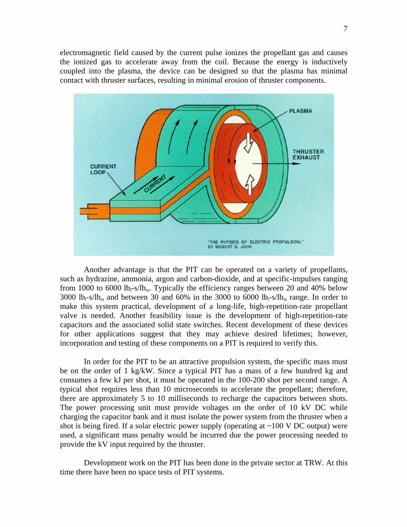
A pulsed inductive thruster (PIT) uses a flat induction coil (approximately 1-m diameter) and a fast gas valve to inject a few milligrams of propellant over the coil. Once the gas has been injected, a bank of high-voltage, high-energy storage capacitors is discharged providing a large azimuthal current pulse to the coil. The time- varying
7
electromagnetic field caused by the current pulse ionizes the propellant gas and causes the ionized gas to accelerate away from the coil. Because the energy is inductively coupled into the plasma, the device can be designed so that the plasma has minimal contact with thruster surfaces, resulting in minimal erosion of thruster components.
Another advantage is that the PIT can be operated on a variety of propellants, such as hydrazine, ammonia, argon and carbon-dioxide, and at specific-impulses ranging from 1000 to 6000 lbf-s/lbm. Typically the efficiency ranges between 20 and 40% below 3000 lbf-s/lbm and between 30 and 60% in the 3000 to 6000 lbf-s/lbm range. In order to make this system practical, development of a long-life, high-repetition-rate propellant valve is needed. Another feasibility issue is the development of high-repetition-rate capacitors and the associated solid state switches. Recent development of these devices for other applications suggest that they may achieve desired lifetimes; however, incorporation and testing of these components on a PIT is required to verify this.
In order for the PIT to be an attractive propulsion system, the specific mass must be on the order of 1 kg/kW. Since a typical PIT has a mass of a few hundred kg and consumes a few kJ per shot, it must be operated in the 100-200 shot per second range. A typical shot requires less than 10 microseconds to accelerate the propellant; therefore, there are approximately 5 to 10 milliseconds to recharge the capacitors between shots. The power processing unit must provide voltages on the order of 10 kV DC while charging the capacitor bank and it must isolate the power system from the thruster when a shot is being fired. If a solar electric power supply (operating at ~100 V DC output) were used, a significant mass penalty would be incurred due the power processing needed to provide the kV input required by the thruster.
Development work on the PIT has been done in the private sector at TRW. At this time there have been no space tests of PIT systems.
8
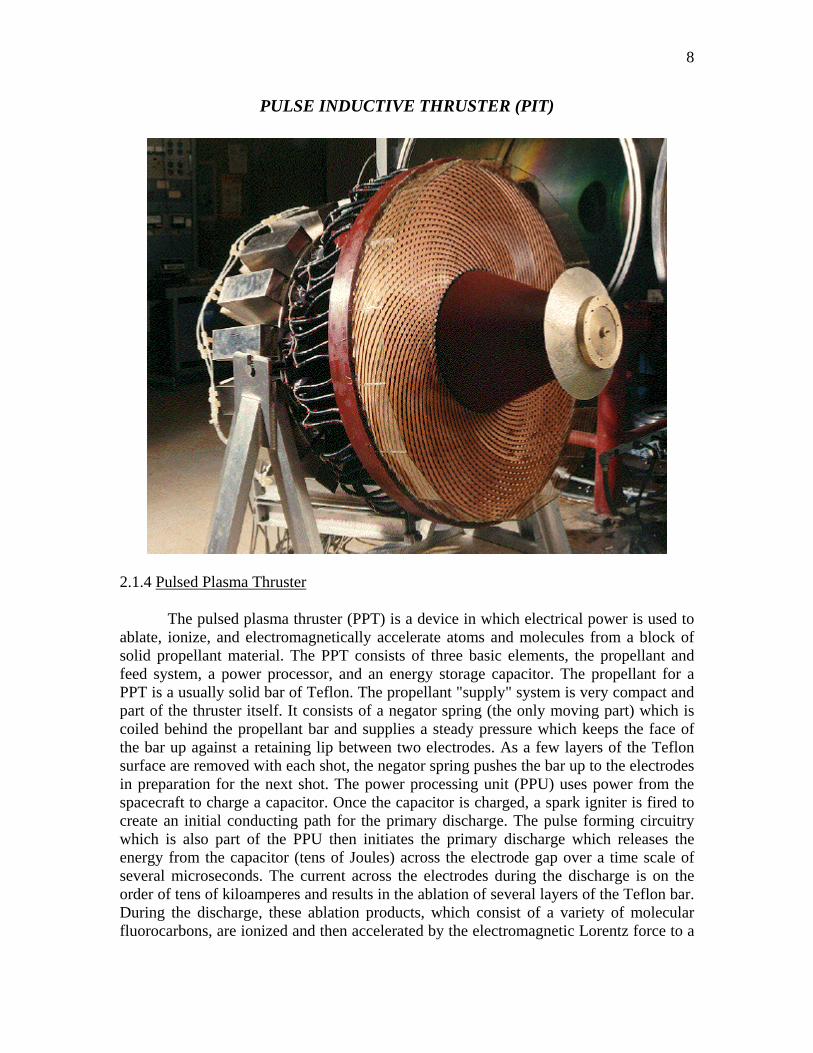
PULSE INDUCTIVE THRUSTER (PIT)
2.1.4 Pulsed Plasma Thruster
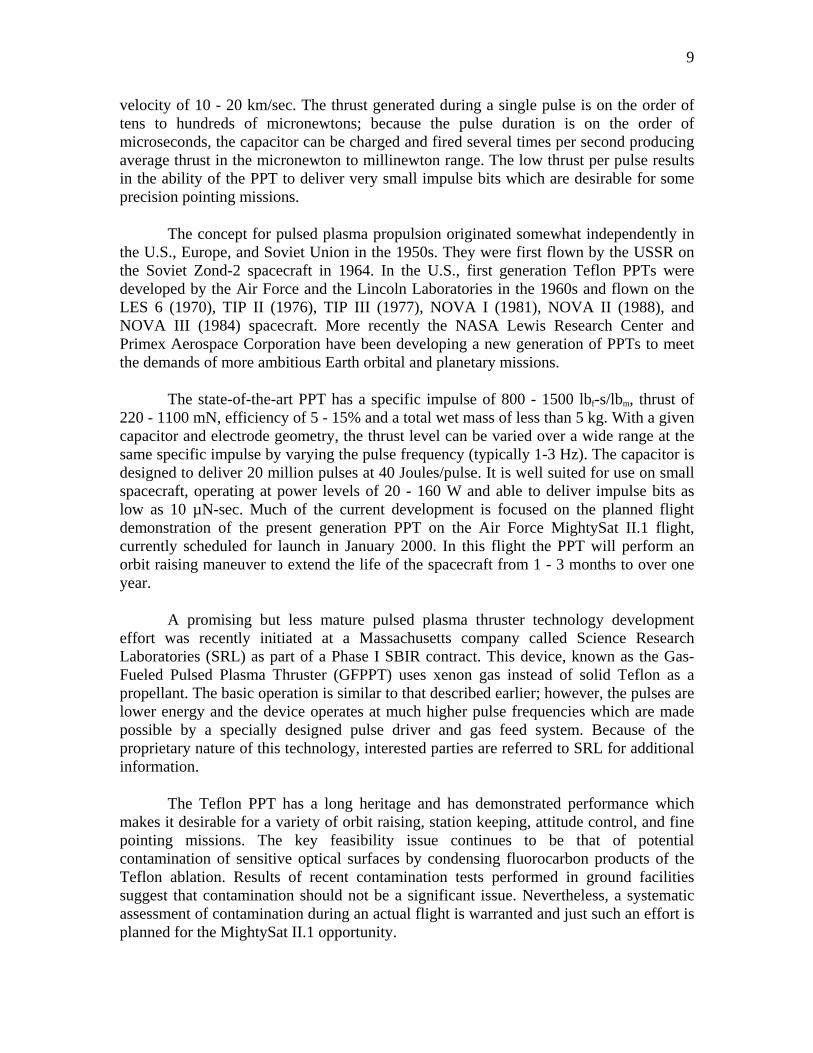
The pulsed plasma thruster (PPT) is a device in which electrical power is used to ablate, ionize, and electromagnetically accelerate atoms and molecules from a block of solid propellant material. The PPT consists of three basic elements, the propellant and feed system, a power processor, and an energy storage capacitor. The propellant for a PPT is a usually solid bar of Teflon. The propellant "supply" system is very compact and part of the thruster itself. It consists of a negator spring (the only moving part) which is coiled behind the propellant bar and supplies a steady pressure which keeps the face of the bar up against a retaining lip between two electrodes. As a few layers of the Teflon surface are removed with each shot, the negator spring pushes the bar up to the electrodes in preparation for the next shot. The power processing unit (PPU) uses power from the spacecraft to charge a capacitor. Once the capacitor is charged, a spark igniter is fired to create an initial conducting path for the primary discharge. The pulse forming circuitry which is also part of the PPU then initiates the primary discharge which releases the energy from the capacitor (tens of Joules) across the electrode gap over a time scale of several microseconds. The current across the electrodes during the discharge is on the order of tens of kiloamperes and results in the ablation of several layers of the Teflon bar. During the discharge, these ablation products, which consist of a variety of molecular fluorocarbons, are ionized and then accelerated by the electromagnetic Lorentz force to a
9
velocity of 10 - 20 km/sec. The thrust generated during a single pulse is on the order of tens to hundreds of micronewtons; because the pulse duration is on the order of microseconds, the capacitor can be charged and fired several times per second producing average thrust in the micronewton to millinewton range. The low thrust per pulse results in the ability of the PPT to deliver very small impulse bits which are desirable for some precision pointing missions.
The concept for pulsed plasma propulsion originated somewhat independently in the U.S., Europe, and Soviet Union in the 1950s. They were first flown by the USSR on the Soviet Zond-2 spacecraft in 1964. In the U.S., first generation Teflon PPTs were developed by the Air Force and the Lincoln Laboratories in the 1960s and flown on the LES 6 (1970), TIP II (1976), TIP III (1977), NOVA I (1981), NOVA II (1988), and NOVA III (1984) spacecraft. More recently the NASA Lewis Research Center and Primex Aerospace Corporation have been developing a new generation of PPTs to meet the demands of more ambitious Earth orbital and planetary missions.
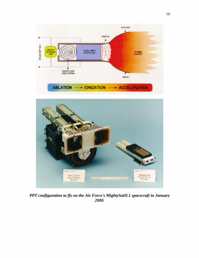
The state-of-the-art PPT has a specific impulse of 800 - 1500 lbf-s/lbm, thrust of 220 - 1100 mN, efficiency of 5 - 15% and a total wet mass of less than 5 kg. With a given capacitor and electrode geometry, the thrust level can be varied over a wide range at the same specific impulse by varying the pulse frequency (typically 1-3 Hz). The capacitor is designed to deliver 20 million pulses at 40 Joules/pulse. It is well suited for use on small spacecraft, operating at power levels of 20 - 160 W and able to deliver impulse bits as low as 10 µN-sec. Much of the current development is focused on the planned flight demonstration of the present generation PPT on the Air Force MightySat II.1 flight, currently scheduled for launch in January 2000. In this flight the PPT will perform an orbit raising maneuver to extend the life of the spacecraft from 1 - 3 months to over one year.
A promising but less mature pulsed plasma thruster technology development effort was recently initiated at a Massachusetts company called Science Research Laboratories (SRL) as part of a Phase I SBIR contract. This device, known as the Gas-Fueled Pulsed Plasma Thruster (GFPPT) uses xenon gas instead of solid Teflon as a propellant. The basic operation is similar to that described earlier; however, the pulses are lower energy and the device operates at much higher pulse frequencies which are made possible by a specially designed pulse driver and gas feed system. Because of the proprietary nature of this technology, interested parties are referred to SRL for additional information.
The Teflon PPT has a long heritage and has demonstrated performance which makes it desirable for a variety of orbit raising, station keeping, attitude control, and fine pointing missions. The key feasibility issue continues to be that of potential contamination of sensitive optical surfaces by condensing fluorocarbon products of the Teflon ablation. Results of recent contamination tests performed in ground facilities suggest that contamination should not be a significant issue. Nevertheless, a systematic assessment of contamination during an actual flight is warranted and just such an effort is planned for the MightySat II.1 opportunity.
10
PPT configuration to fly on the Air Force's MightySatII.1 spacecraft in January 2000.
11
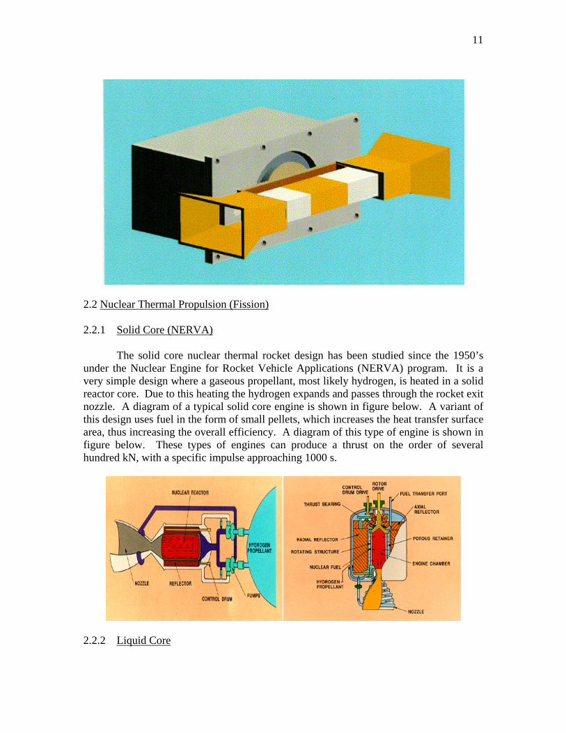
2.2 Nuclear Thermal Propulsion (Fission) 2.2.1 Solid Core (NERVA)
The solid core nuclear thermal rocket design has been studied since the 1950’s under the Nuclear Engine for Rocket Vehicle Applications (NERVA) program. It is a very simple design where a gaseous propellant, most likely hydrogen, is heated in a solid reactor core. Due to this heating the hydrogen expands and passes through the rocket exit nozzle. A diagram of a typical solid core engine is shown in figure below. A variant of this design uses fuel in the form of small pellets, which increases the heat transfer surface area, thus increasing the overall efficiency. A diagram of this type of engine is shown in figure below. These types of engines can produce a thrust on the order of several hundred kN, with a specific impulse approaching 1000 s.
2.2.2 Liquid Core
12
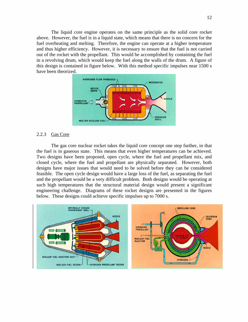
The liquid core engine operates on the same principle as the solid core rocket above. However, the fuel is in a liquid state, which means that there is no concern for the fuel overheating and melting. Therefore, the engine can operate at a higher temperature and thus higher efficiency. However, it is necessary to ensure that the fuel is not carried out of the rocket with the propellant. This would be accomplished by containing the fuel in a revolving drum, which would keep the fuel along the walls of the drum. A figure of this design is contained in figure below. With this method specific impulses near 1500 s have been theorized.
2.2.3 Gas Core
The gas core nuclear rocket takes the liquid core concept one step further, in that the fuel is in gaseous state. This means that even higher temperatures can be achieved. Two designs have been proposed, open cycle, where the fuel and propellant mix, and closed cycle, where the fuel and propellant are physically separated. However, both designs have major issues that would need to be solved before they can be considered feasible. The open cycle design would have a large loss of the fuel, as separating the fuel and the propellant would be a very difficult problem. Both designs would be operating at such high temperatures that the structural material design would present a significant engineering challenge. Diagrams of these rocket designs are presented in the figures below. These designs could achieve specific impulses up to 7000 s.
13
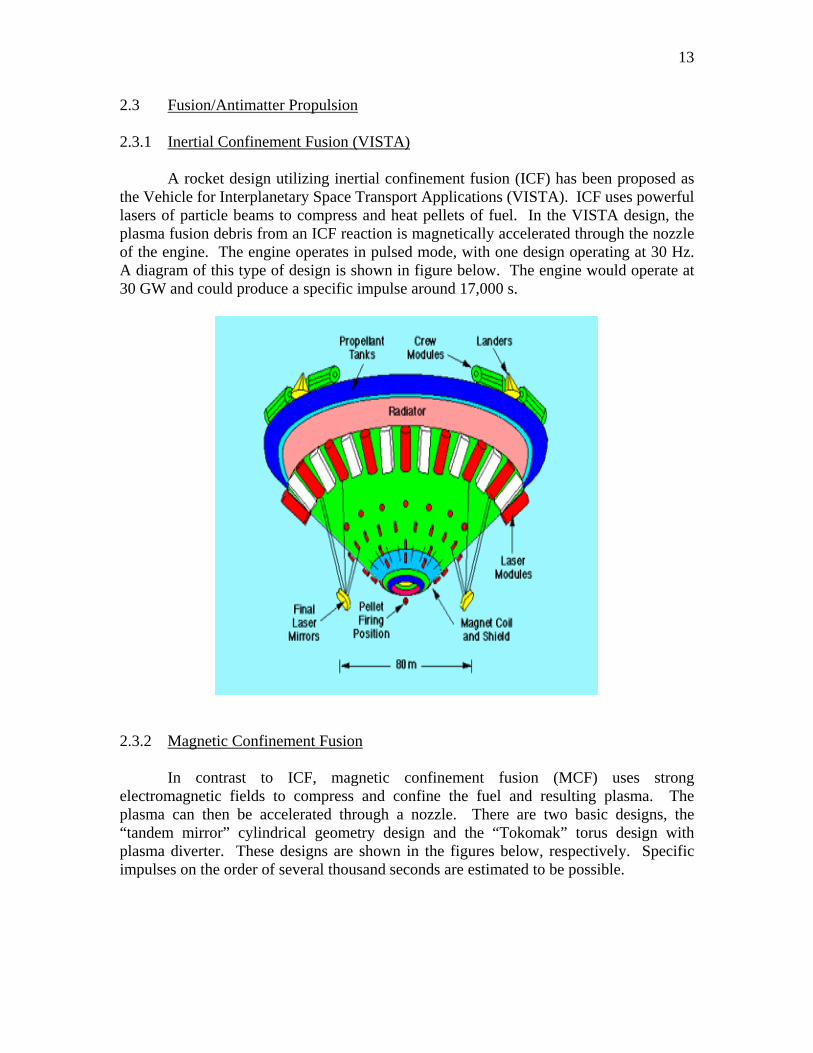
2.3 Fusion/Antimatter Propulsion 2.3.1 Inertial Confinement Fusion (VISTA) A rocket design utilizing inertial confinement fusion (ICF) has been proposed as the Vehicle for Interplanetary Space Transport Applications (VISTA). ICF uses powerful lasers of particle beams to compress and heat pellets of fuel. In the VISTA design, the plasma fusion debris from an ICF reaction is magnetically accelerated through the nozzle of the engine. The engine operates in pulsed mode, with one design operating at 30 Hz. A diagram of this type of design is shown in figure below. The engine would operate at 30 GW and could produce a specific impulse around 17,000 s.
2.3.2 Magnetic Confinement Fusion
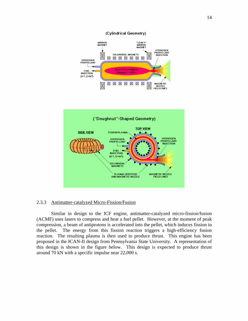
In contrast to ICF, magnetic confinement fusion (MCF) uses strong electromagnetic fields to compress and confine the fuel and resulting plasma. The plasma can then be accelerated through a nozzle. There are two basic designs, the “tandem mirror” cylindrical geometry design and the “Tokomak” torus design with plasma diverter. These designs are shown in the figures below, respectively. Specific impulses on the order of several thousand seconds are estimated to be possible.
14
2.3.3 Antimatter-catalyzed Micro-Fission/Fusion
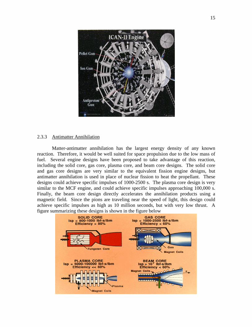
Similar in design to the ICF engine, antimatter-catalyzed micro-fission/fusion (ACMF) uses lasers to compress and heat a fuel pellet. However, at the moment of peak compression, a beam of antiprotons is accelerated into the pellet, which induces fission in the pellet. The energy from this fission reaction triggers a high-efficiency fusion reaction. The resulting plasma is then used to produce thrust. This engine has been proposed in the ICAN-II design from Pennsylvania State University. A representation of this design is shown in the figure below. This design is expected to produce thrust around 70 kN with a specific impulse near 22,000 s.
15
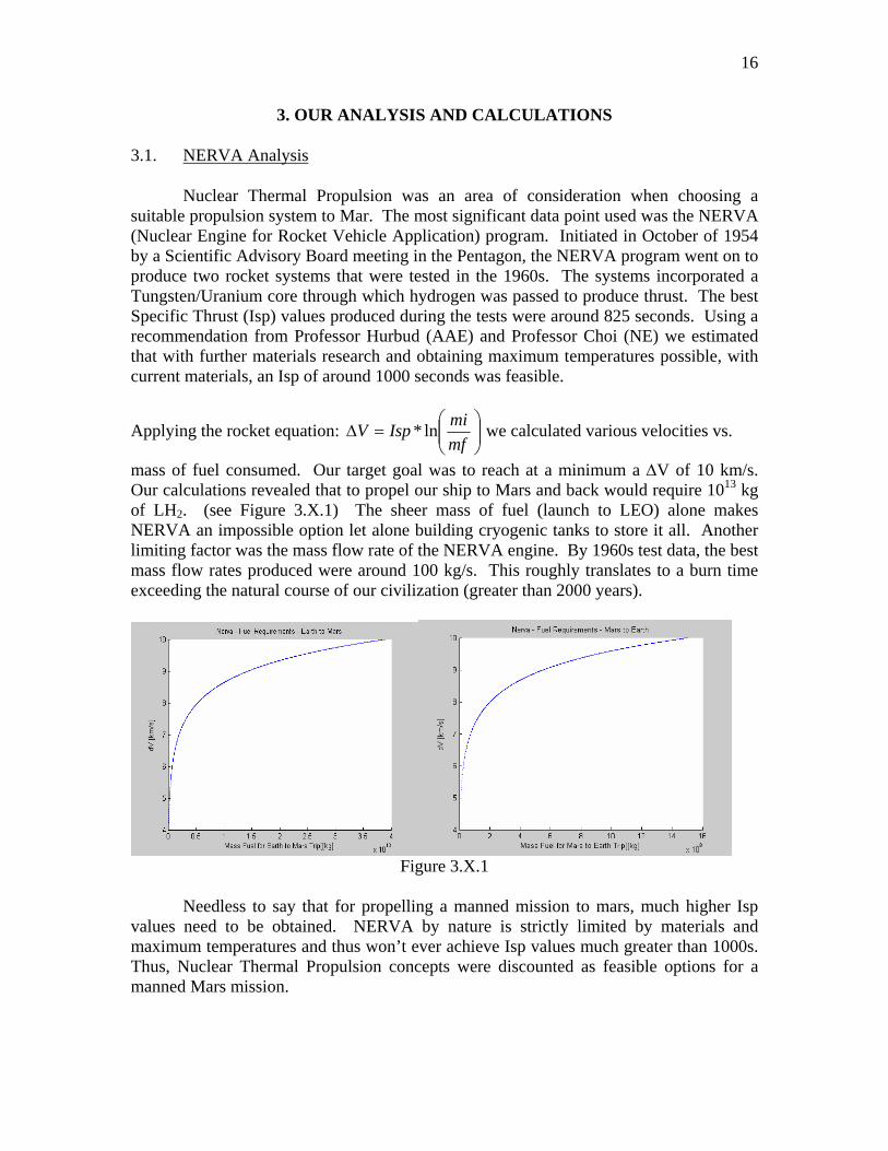
2.3.3 Antimatter Annihilation Matter-antimatter annihilation has the largest energy density of any known reaction. Therefore, it would be well suited for space propulsion due to the low mass of fuel. Several engine designs have been proposed to take advantage of this reaction, including the solid core, gas core, plasma core, and beam core designs. The solid core and gas core designs are very similar to the equivalent fission engine designs, but antimatter annihilation is used in place of nuclear fission to heat the propellant. These designs could achieve specific impulses of 1000-2500 s. The plasma core design is very similar to the MCF engine, and could achieve specific impulses approaching 100,000 s. Finally, the beam core design directly accelerates the annihilation products using a magnetic field. Since the pions are traveling near the speed of light, this design could achieve specific impulses as high as 10 million seconds, but with very low thrust. A figure summarizing these designs is shown in the figure below
16
3. OUR ANALYSIS AND CALCULATIONS
3.1. NERVA Analysis
Nuclear Thermal Propulsion was an area of consideration when choosing a suitable propulsion system to Mar. The most significant data point used was the NERVA (Nuclear Engine for Rocket Vehicle Application) program. Initiated in October of 1954 by a Scientific Advisory Board meeting in the Pentagon, the NERVA program went on to produce two rocket systems that were tested in the 1960s. The systems incorporated a Tungsten/Uranium core through which hydrogen was passed to produce thrust. The best Specific Thrust (Isp) values produced during the tests were around 825 seconds. Using a recommendation from Professor Hurbud (AAE) and Professor Choi (NE) we estimated that with further materials research and obtaining maximum temperatures possible, with current materials, an Isp of around 1000 seconds was feasible.
Applying the rocket equation: ⎟⎟⎠
⎞⎜⎜⎝
⎛=∆
mfmiIspV ln* we calculated various velocities vs.
mass of fuel consumed. Our target goal was to reach at a minimum a ∆V of 10 km/s. Our calculations revealed that to propel our ship to Mars and back would require 1013 kg of LH2. (see Figure 3.X.1) The sheer mass of fuel (launch to LEO) alone makes NERVA an impossible option let alone building cryogenic tanks to store it all. Another limiting factor was the mass flow rate of the NERVA engine. By 1960s test data, the best mass flow rates produced were around 100 kg/s. This roughly translates to a burn time exceeding the natural course of our civilization (greater than 2000 years).
Figure 3.X.1
Needless to say that for propelling a manned mission to mars, much higher Isp
values need to be obtained. NERVA by nature is strictly limited by materials and maximum temperatures and thus won’t ever achieve Isp values much greater than 1000s. Thus, Nuclear Thermal Propulsion concepts were discounted as feasible options for a manned Mars mission.
17
3.2 Sample Calculations
∆V Calculations:
⎟⎟⎠
⎞⎜⎜⎝
⎛=∆
mfmiIspV ln*
NEP Sample (Earth to Mars):
⎟⎠⎞
⎜⎝⎛=∆
271250947250ln*)8000(V = 10,000 m/s
Burn-time Calculations:
mmfuelbt&
=
NEP Sample (Mars to Earth):
dayss
daykg
skgbt 91.13600*24
1*1
*165300==
3.3 MATLAB Code
3.3.1 Code for Earth to Mars Transfer %Thrust Analysis %NUCL 497S, Group 2 %Fall 2003 clf clc clear hold on mdry = 105950; %[kg] - Dry Mass mfuel2 = 165300; %[kg] - Return trip fuel mass %[kg] - Initial Mass of Mars <-> Earth Transfer Fuels Isp = 8000; % hold on for mfuel1 = 10000:1000:1000000000%[kg] - Earth to Mars transfer fuel [lithium or ion fuel] mf = mdry + mfuel2; %[kg] - Final Mass After Earth-Mars Transfer Burn dV = Isp*log((mfuel1+mdry+mfuel2)/mf); if dV >= 10000 dV mfuel1 break break end plot(mfuel1,(dV/1000))
18
end ylabel('dV [km/s]') xlabel('Mass Fuel for Earth to Mars Trip[[kg]') title('Pulsed Inductive Thruster Array - Fuel Requirements - Earth to Mars') mfrthrstr = 10; %[g/sec] mfr = (mfrthrstr/1000)*(100); %[kg/s] bt = (mfuel1/mfr)/(3600*24) %Burntime [days] 3.3.2 Code for Mars to Earth Transfer %Thrust Analysis %NUCL 497S, Group 2 %Fall 2003 clf clc clear hold on mdry = 66351; %[kg] - Dry Mass Isp = 8000; % hold on for mfuel2 = 1000:100:9000000 %[kg] - Earth to Mars transfer fuel [lithium or ion fuel] mf = mdry; %[kg] - Final Mass After Earth-Mars Transfer Burn dV = Isp*log((mdry+mfuel2)/mf); if dV >= 10000 dV mfuel2 break break end plot(mfuel2,(dV/1000)) end ylabel('dV [km/s]') xlabel('Mass Fuel for Mars to Earth Trip[[kg]') title('Pulsed Inductive Thruster Array - Fuel Requirements - Mars to Earth') mfrthrstr = 10; %[g/sec] mfr = (mfrthrstr/1000)*(100); %[kg/s] bt = (mfuel2/mfr)/(3600*24) %Burntime [days]
19
3.4 Pulsed Inductive Thruster Analysis In the limited scope of our understanding of NEP we made a few major assumptions which add a significant amount of uncertainty and error to our analysis. For the simple goal of understanding the most viable option for NEP, we assumed the following:
a. The equation: ⎟⎟⎠
⎞⎜⎜⎝
⎛=∆
mfmiIspV ln* applies
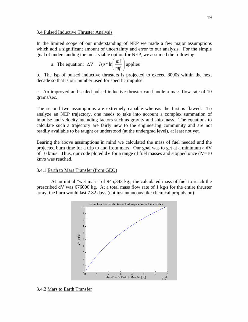
b. The Isp of pulsed inductive thrusters is projected to exceed 8000s within the next decade so that is our number used for specific impulse. c. An improved and scaled pulsed inductive thruster can handle a mass flow rate of 10 grams/sec. The second two assumptions are extremely capable whereas the first is flawed. To analyze an NEP trajectory, one needs to take into account a complex summation of impulse and velocity including factors such as gravity and ship mass. The equations to calculate such a trajectory are fairly new to the engineering community and are not readily available to be taught or understood (at the undergrad level), at least not yet. Bearing the above assumptions in mind we calculated the mass of fuel needed and the projected burn time for a trip to and from mars. Our goal was to get at a minimum a dV of 10 km/s. Thus, our code ploted dV for a range of fuel masses and stopped once dV=10 km/s was reached. 3.4.1 Earth to Mars Transfer (from GEO)
At an initial “wet mass” of 945,343 kg., the calculated mass of fuel to reach the prescribed dV was 676000 kg. At a total mass flow rate of 1 kg/s for the entire thruster array, the burn would last 7.82 days (not instantaneous like chemical propulsion).
3.4.2 Mars to Earth Transfer
20
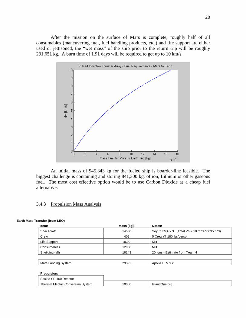
After the mission on the surface of Mars is complete, roughly half of all
consumables (maneuvering fuel, fuel handling products, etc.) and life support are either used or jettisoned, the “wet mass” of the ship prior to the return trip will be roughly 231,651 kg. A burn time of 1.91 days will be required to get up to 10 km/s.
An initial mass of 945,343 kg for the fueled ship is boarder-line feasible. The biggest challenge is containing and storing 841,300 kg. of ion, Lithium or other gaseous fuel. The most cost effective option would be to use Carbon Dioxide as a cheap fuel alternative. 3.4.3 Propulsion Mass Analysis
Earth Mars Transfer (from LEO) Item: Mass [kg]: Notes: Spacecraft 14500 Soyuz TMA x 3 (Total Vh = 18 m^3 or 635 ft^3) Crew 408 5 Crew @ 180 lbs/person Life Support 4600 MIT Consumables 12000 MIT Sheilding (all) 18143 20 tons - Estimate from Team 4 Mars Landing System 29392 Apollo LEM x 2 Propulsion:
Scaled SP-100 Reactor Thermal Electric Conversion System 10000 IslandOne.org
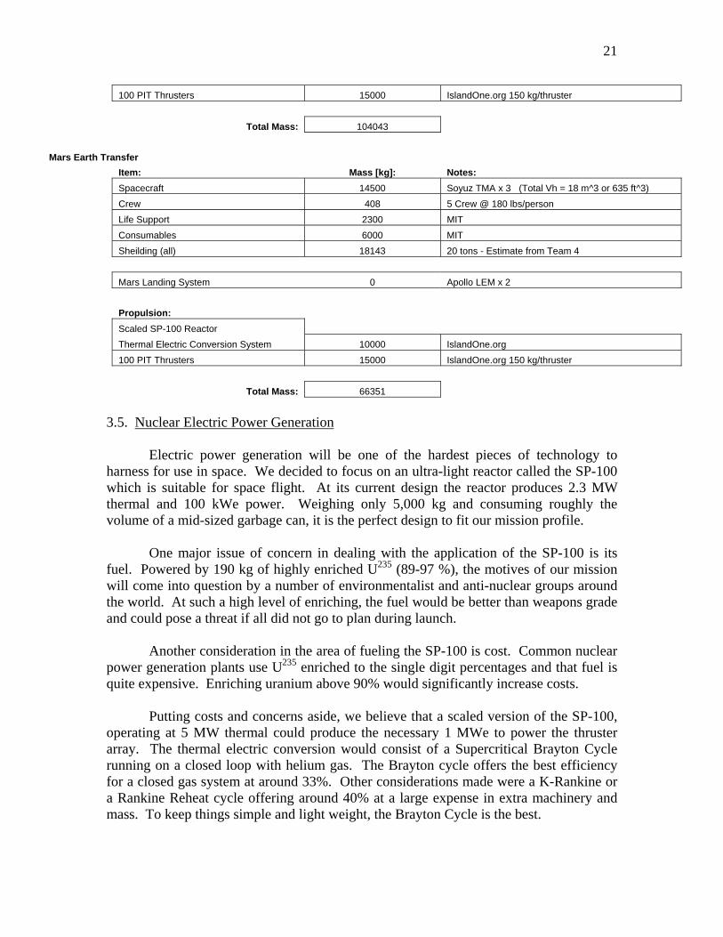
21
100 PIT Thrusters 15000 IslandOne.org 150 kg/thruster Total Mass: 104043 Mars Earth Transfer Item: Mass [kg]: Notes: Spacecraft 14500 Soyuz TMA x 3 (Total Vh = 18 m^3 or 635 ft^3) Crew 408 5 Crew @ 180 lbs/person Life Support 2300 MIT Consumables 6000 MIT Sheilding (all) 18143 20 tons - Estimate from Team 4 Mars Landing System 0 Apollo LEM x 2 Propulsion:
Scaled SP-100 Reactor Thermal Electric Conversion System 10000 IslandOne.org 100 PIT Thrusters 15000 IslandOne.org 150 kg/thruster Total Mass: 66351
3.5. Nuclear Electric Power Generation
Electric power generation will be one of the hardest pieces of technology to harness for use in space. We decided to focus on an ultra-light reactor called the SP-100 which is suitable for space flight. At its current design the reactor produces 2.3 MW thermal and 100 kWe power. Weighing only 5,000 kg and consuming roughly the volume of a mid-sized garbage can, it is the perfect design to fit our mission profile.
One major issue of concern in dealing with the application of the SP-100 is its
fuel. Powered by 190 kg of highly enriched U235 (89-97 %), the motives of our mission will come into question by a number of environmentalist and anti-nuclear groups around the world. At such a high level of enriching, the fuel would be better than weapons grade and could pose a threat if all did not go to plan during launch.
Another consideration in the area of fueling the SP-100 is cost. Common nuclear
power generation plants use U235 enriched to the single digit percentages and that fuel is quite expensive. Enriching uranium above 90% would significantly increase costs.
Putting costs and concerns aside, we believe that a scaled version of the SP-100,
operating at 5 MW thermal could produce the necessary 1 MWe to power the thruster array. The thermal electric conversion would consist of a Supercritical Brayton Cycle running on a closed loop with helium gas. The Brayton cycle offers the best efficiency for a closed gas system at around 33%. Other considerations made were a K-Rankine or a Rankine Reheat cycle offering around 40% at a large expense in extra machinery and mass. To keep things simple and light weight, the Brayton Cycle is the best.
22
In using a thermodynamic cycle to produce electricity, we need to incorporate a large system to radiate waste energy during the constant pressure heat rejection step of the cycle. To produce 1 MWe we would have to dump 3.35 MW of thermal energy out into space. This will require a large radiator array which will have to be incorporated into our ships design.
4. COST ANALYSIS
4.1 Components
There are several components to calculating the cost of a mission or missions to mars. There are many things that need to be taken care of. Items such as earth based mission control and monitoring equipment and personnel. Another consideration is the space lift of all of the components of the space ship and the assembly of the ship in space. There is also the cost of the actual vehicle to be designed and built for the mission. And lastly there is the Recovery teams needed to recover our spacecraft and human mars pioneers after the mission ensuring their safety and the environmental and inhabitants of earth. 4.1.1 Mission Support NASA’s current budget for Mission support is 2.9 Billion dollars a year to ensure all the space missions being conducted are taken care of adequately. The Mars mission will no doubt require many more human resources with will make the cost absurdly high. The mission will be taking about a year and a half in which mission control must be manned 24 hours a day 7 days a week to support the crew. There will need to be Space weather monitoring to predict and monitor solar flares and radiation hazards to the crew. Along with live references for all major systems and large communication and data transferring capabilities, cost of the mission skyrockets. New facilities designed for the mission along with new tools to build and maintain the spacecraft must also be built. These are just a few of the things that will add to the cost of mission support. 4.1.2 Space Lift There are many options out there for launch vehicles; however for this mission it has been determined that something similar to a Titan IV would be the best rocket to compare costs of lunches with. A larger rocket like the Saturn V would be better suited to launching the components of the spaceship, however the rocket is very old and out dated. So its cost for launches would not be as accurate as the Titan IV. The Titan IV can launch 21,700 kilograms per launch at a cost of $19,000 per kilogram, putting the payload in to a Low Earth Orbit(LEO) with the International Space Station(ISS) With a launch cost of about 140 million dollars per launch with 44 launches needed to get the parts to orbit for the assembly of the spaceship. It will be approximately 6.16 billion dollars just to get the pieces to LEO for assembly at the ISS. 4.1.3 Vehicle Components
23
There will be much cost to the components of the space vehicle along with the
vehicle itself. Some components to keep in mind are the engine development and production costs. This is be very costly due to the new nature of the technology and the fact that we will need to produce a large array of the most powerful thrusters we can manufacture, with the best specific impulse available. Another component to consider is the shielding that will need to be developed to protect the crew and instrumentation from harmful radiation both from space and the nuclear reactor on board providing power for the engines and spacecraft. The cost of research and fabrication could be considerable. The actual structures developed in the space craft weather composite or metal will need to be developed to maintain a level of safety for the stress and strains the spacecraft may endure in it flight. Other things the will add to the cost are the required communications equipment that will have to operate over long distances between earth and Mars in possibly harsh space conditions that could interfere with the avionics. Cost of development of sophisticated equipment along with sophisticated life support equipment will need to also be factored in.
4.1.4 Recovery There will have to be rescue and recovery teams on standby by for when the crew launches to the International Space station for the beginning or their mission and when the crew returns to earth from their mission. These crews are deployed to the landing sites and the military often aids in being on standby to assist in search and rescue. Transportation cost for the crew up to the station and back could be taken care of with the current shuttles or what next space vehicle we have for transportation to and from the ISS. Hazardous waste and materials disposal is another costly resource required for space flight. Most space flight involves using chemicals and materials that are often toxic or harmful to living organisms. These crews typically contain or remove these hazardous parts for the space shuttle and make it safe for people to examine the crew and clear the return vehicle.
The mission to Mars will be a costly one for sure. Exact costs are hard to predict because so much needs to be done in research and development of new technologies. The mission requires many things that are not exactly off the shelf technology so new things will have to be developed to make the mission obtainable. This will be a costly investment but will definitely pay off in the long run in benefits to the world in new technologies such as what happened when the United States decided to go the moon. So many new technologies that previously were not heard of suddenly became technologies everyday people stated finding uses for. So is this huge cost of a manned mission to mars worth it? The answer is yes, because the world will gain much in new technology from the research and development still needed to be done to make this mission a reality.
5. RECOMMENDATIONS
It won’t be too much longer until humanity experiences the next Apollo 11. Mars will only be the first domino that will set off a countless series of new space exploration
24
expeditions. With execution of our options at hand, and further research in propulsion humanity will have the power and knowledge to not only take a giant leap forward, but also have a running start.
6. SOURCES
“Nuclear Thermal Propulsion.” Online. Available: http://128.227.144.214/research/ntp.html November 24, 2003 “History of U.S. Nuclear Space Program.” Online. Available:
http://starfire.ne.uiuc.edu/~ne201/1996/space/history.html November 24, 2003. “Thermal Nuclear Propulsion.” Online. Available:
http://engineering.rowan.edu/~lapi5653/Report3.html November 24, 2003 “Getting More Miles Per Gallon.” Online. Available: http://www.astrodigital.org/space/nuclear.html November 24, 2003 “Advanced Propulsion Concepts.” Online. Available: http://sec353.jpl.nasa.gov/apc/index.html December 5, 2003 Chang Diaz, Franklin R. “The VASIMR Rocket.” Scientific American November 2000:
90-97 “VASIMR.” Online. Available: http://204.121.16.115:81/spacenuke/subpages/aspl.htm November 24, 2003 “VASIMR.” Online. Availabe:
http://memebers.optusnet.com.au/~tdharvy/Space/Vasimr.htm November 24, 2003
“Launch and Propulsion systems.” Online. Available:
http://www.hobbyspace.com/Links/LaunchPropulsion.html December 5, 2003
“NERVA History.” Online Available: http://www.astronautix.com/ December 6, 2003 **One site of note that contributed significantly to this report was www.islandone.org/APC, numerous articles were taken and used off of this website and used directly.


![Interstellar 2014 - Interstellar 2014 HDCAM [[ENG]]](https://img.pdfslide.us/doc/110x75/577cc0fb1a28aba71191d2d3/interstellar-2014-interstellar-2014-hdcam-eng.jpg)
