Embed Size (px)
Citation preview
M7-13
FABRICATION STANDARDS
COMMUNICATIONS & POWER INDUSTRIES LLCMICROWAVE POWER PRODUCTS DIVISION
Revision: BC
ECO: MPP622853March 5, 2021
MANUFACTURING SPECIFICATION
FABRICATION STANDARDSSpec. No.: M7-13
ECO: MPP622853 Rev. BC
Date: March 5, 2021
Page i of iii
Communications & Power Industries LLC � Microwave Power Products Division � P.O. Box 50750 � Palo Alto � California � 94303-0750
TABLE OF CONTENTS
PREFACE ................................................................................................................................................... 1
REFERENCES ............................................................................................................................................ 1
DEFINITIONS.............................................................................................................................................. 1
1.0 RAW MATERIALS............................................................................................................................ 2
2.0 STANDARDS FOR RAW-MATERIAL MACHINING ALLOWANCES................................................ 3
2.1 Minimums.............................................................................................................................. 3
2.2 Calculation of Raw-Material Dimensions ............................................................................... 3
2.3 Tubing................................................................................................................................... 5
3.0 CERTIFICATION .............................................................................................................................. 5
3.1 Delivery or Storage of Certifications ..................................................................................... 5
3.2 Requirements on All Certifications ........................................................................................ 6
3.3 Certification Types ................................................................................................................ 6
4.0 PACKAGING AND LABELING ......................................................................................................... 7
4.1 Parts Protection in Packing ................................................................................................... 7
4.2 Transportation....................................................................................................................... 8
4.3 Package Labeling ................................................................................................................. 9
4.4 Packaging and Labeling of Beryllium Containing Parts and Materials .................................. 9
5.0 GEOMETRIC DIMENSIONING AND TOLERANCING SYSTEM .................................................... 10
5.1 Unspecified Tolerance ........................................................................................................ 10
5.2 Unspecified Finish .............................................................................................................. 10
5.3 Unspecified Flatness .......................................................................................................... 10
5.4 Unspecified Cylindricity ....................................................................................................... 11
5.5 Unspecified Perpendicularity .............................................................................................. 11
5.6 Unspecified Parallelism....................................................................................................... 11
5.7 Unspecified Concentricity ................................................................................................... 11
5.8 Unspecified Position ........................................................................................................... 12
5.9 Unspecified Circularity ........................................................................................................ 12
5.10 Unspecified Countersinks ................................................................................................... 12
6.0 TOOLING ....................................................................................................................................... 12
7.0 CLEANING, PLATING, AND COATING OF SURFACES ............................................................... 12
8.0 BURRS........................................................................................................................................... 13
8.1 Definition............................................................................................................................. 13
MANUFACTURING SPECIFICATION
FABRICATION STANDARDSSpec. No.: M7-13
ECO: MPP622853 Rev. BC
Date: March 5, 2021
Page ii of iii
Communications & Power Industries LLC � Microwave Power Products Division � P.O. Box 50750 � Palo Alto � California � 94303-0750
8.2 Types .................................................................................................................................. 13
8.3 Height ................................................................................................................................. 13
8.4 Removal.............................................................................................................................. 13
8.5 Edges ................................................................................................................................. 14
8.6 Corners ............................................................................................................................... 14
8.7 Sheet Metal......................................................................................................................... 15
9.0 THREADS ...................................................................................................................................... 15
9.1 Internal Threads.................................................................................................................. 15
9.2 Threaded Holes .................................................................................................................. 15
9.3 Threaded Parts ................................................................................................................... 16
9.4 Full-Form Threads .............................................................................................................. 16
9.5 Unspecified Thread Class of Fit .......................................................................................... 16
10.0 SHEET-METAL PRODUCTS FABRICATION REQUIREMENTS ................................................... 16
10.1 Sheet Metal......................................................................................................................... 16
10.2 Features and Surfaces ....................................................................................................... 16
10.3 Machined Features ............................................................................................................. 16
10.4 Circular Runout ................................................................................................................... 17
10.5 Washer-Type Punching ...................................................................................................... 17
10.6 Flatness .............................................................................................................................. 17
10.7 Parallelism and Perpendicularity ......................................................................................... 18
10.8 Edges and Corners ............................................................................................................. 18
10.9 Stock Thickness after Forming ........................................................................................... 18
10.10 Breakaway .......................................................................................................................... 18
10.11 Burrs ................................................................................................................................... 19
10.12 Burr Symbols and Drawing Callouts ................................................................................... 19
11.0 CASTING AND FORGING REQUIREMENTS ................................................................................ 19
11.1 Position ............................................................................................................................... 20
11.2 Flatness .............................................................................................................................. 20
11.3 Cleanup .............................................................................................................................. 21
11.4 Mismatch ............................................................................................................................ 21
11.5 Draft .................................................................................................................................... 21
11.6 Repair ................................................................................................................................. 21
12.0 EDM FABRICATION REQUIREMENTS ......................................................................................... 21
APPENDIX: Geometric Symbology ............................................................................................... 22
MANUFACTURING SPECIFICATION
FABRICATION STANDARDSSpec. No.: M7-13
ECO: MPP622853 Rev. BC
Date: March 5, 2021
Page 1 of 23
Revision InformationUpdated to add clarification on minimum raw material stock size in Section 2.2.
ATTENTIONUNLESS OTHERWISE SPECIFIED ON THE PURCHASE ORDER(S) OR CPI INTERNAL
SHOP WORK ORDER(S), CONFORMANCE TO ALL REQUIREMENTS OF THE DRAWING(S) AND SPECIFICATION(S) IS MANDATORY.
PREFACE
The object of the Fabrication Standards Specification M7-13 is to supplement the design information on CPI drawings for microwave Vacuum Electron Device (VED) assemblies and components. Suppliers and CPI manufacturing units shall be responsible for the implementation of these standards in the performance of work for CPI as outlined in CPI purchase orders and shop work orders.
This standard reflects the technical requirements for the Microwave Power Products Division (MPP) of Communications and Power Industries LLC.
The previous Section 6.0, “Coolants, Lubricants, and Solvents,” which has been a part of past revisions, is now a separate, subordinate document (M7-179, “Approved Lubricants, Coolants, and Solvents”) to facilitate subsequent revisions. All data therein are still considered flow-down requirements from M7-13.
Failure to comply with the requirements contained in the Fabrication Standards may result in the
rejection of the material produced. In the event of a conflict between the standards, the drawing,
and/or the purchase order, the purchase order shall take precedence, the drawing next, and then
the standards.
All questions from Suppliers concerning the interpretation of the standards shall be directed to the CPI MPP Purchasing Department. Additional information or revisions shall be provided to Suppliers and all CPI departments engaged in fabrication of piece parts, subassemblies, and finished products.
REFERENCES (Latest Revision)
40 CFR, Part 82 Protection of Stratospheric Ozone ASME Y14.5 Dimensions and TolerancingFED-STD-H28 Screw Thread Standards for Federal ServicesCPI M7-35 Inventory PackagingCPI M7-179 Approved Lubricants, Coolants, and SolventsCPI P0-1 Approved Sources for Raw Materials and Processes (Including Sections 1,
2, 3, and 4)CPI P0-3 Supplier Quality System RequirementsCPI P18-2 Clean Packaging of Supplier-Provided Parts
DEFINITIONS
CMM Coordinate Measuring MachineEDM Electrical Discharge MachiningEPA Environmental Protection AgencyMMC Maximum Material Condition Non-Vacuum Assembly An assembly that is not within or part of the vacuum envelopeNon-Vacuum Part A part that is not within or part of the vacuum envelopeOFE Oxygen Free Electronic

MANUFACTURING SPECIFICATION
FABRICATION STANDARDSSpec. No.: M7-13
ECO: MPP622853 Rev. BC
Date: March 5, 2021
Page 2 of 23
PO Purchase OrderP-Spec Purchasing SpecificationRFS Regardless of Feature SizeVacuum Assembly An assembly that is within or part of the vacuum envelopeVacuum Part A part that is within or part of the vacuum envelopeVED Vacuum Electron Device (modern name for “microwave tube”)1.0 RAW MATERIALS
The performance of VEDs is critically dependent upon the strict conformance of raw materials to specifications and to proper processing and cleanliness practices. CPI’s products are subjected to numerous high-temperature cycles during their assembly and processing and must still retain high- vacuum integrity, strength, and inherent thermal and magnetic properties. To this end, the Supplier shall be required to use ONLY the material specified on the drawing or on the PO to fabricate the required parts.
NOTEUSE OF UNAUTHORIZED MATERIAL IS NOT ALLOWED.
Violations shall result in removal from the Approved Supplier List and possible exposure to consequential damages.
Some of the raw materials used by CPI have directional properties resulting from segregation or inclusions that can seriously jeopardize the vacuum integrity of microwave VEDs. For example,
Low-carbon steels have regions of high-carbon content.
Stainless steels contain sulfide or oxide inclusions.
Cupronickel occasionally exhibits slag inclusions.
During ingot reduction, these concentrations of impurities are “stretched out” in the rolling or drawing direction, forming “stringers” (i.e., in the plane of flat or sheet stock and on the axis for bar stock). CPI parts that are designed for vacuum applications will always prescribe a material orientation to ensure that a potential stringer leak path will run parallel to the vacuum wall instead of piercing it. Allowable forms are defined in the purchasing specification (P-Spec) and denoted in the materials block of individual drawings by a P-Spec suffix. The “Grain Symbol” (
GRAIN ) may also be used in instances of critical orientation.
Sourcing of raw materials shall be in strict accordance with CPI P0-1, “Approved Sources for Raw Materials and Processes.”
All raw materials must be positively identified and directly traceable to the certifications that demonstrate the material’s conformance to stated requirements.
Surplus material, including remnants, overage, and scrap, that cannot be traced directly to its certifications shall under no circumstances be used to fabricate parts for CPI.
Alternate forms of raw materials (i.e., plate, bar, sheet, etc.) may not be substituted without written approval from CPI.
It is unallowable to use welded tubing or to roll and weld flat stock unless specifically prescribed in the drawing or PO.
It is unallowable to repair parts by welding, plugging, flame spraying, or other methods without written approval from CPI.
MANUFACTURING SPECIFICATION
FABRICATION STANDARDSSpec. No.: M7-13
ECO: MPP622853 Rev. BC
Date: March 5, 2021
Page 3 of 23
2.0 STANDARDS FOR RAW-MATERIAL MACHINING ALLOWANCES
This section prescribes machining allowances for raw materials to ensure the removal of surface defects and oxides. Material with no allowance has been demonstrated to have a useable surface as received.
2.1 Minimums
The allowances specified are minimums to be removed from each side. Where greater amounts must be removed, it is recommended that an equal amount be removed from both sides as permitted by available raw-material dimensions. If surface defects are still visible after removal of the machining allowance, the material should not be used at all.
2.2 Calculation of Raw-Material Dimensions
The minimum size of the raw material shall be determined as follows:
Determine the “Finished” dimension from the print and ADD the following amounts:
For Chromium Copper/Chromium Zirconium Copper Alloys
(All Forms Except Castings and Forgings)
Under 0.250″ Thick 0.251″ to 1.000″ Thick Above 1.000″ Thick
0.020″ from each surface 0.030″ from each surface 0.060″ from each surface
For Chromium Copper/Chromium Zirconium Copper Alloys Castings and Forgings
Under 0.250″ Thick 0.251″ to 1.000″ Thick Above 1.000″ Thick
0.020″ from each surface 0.10″ from each surface 0.50″ from each surface
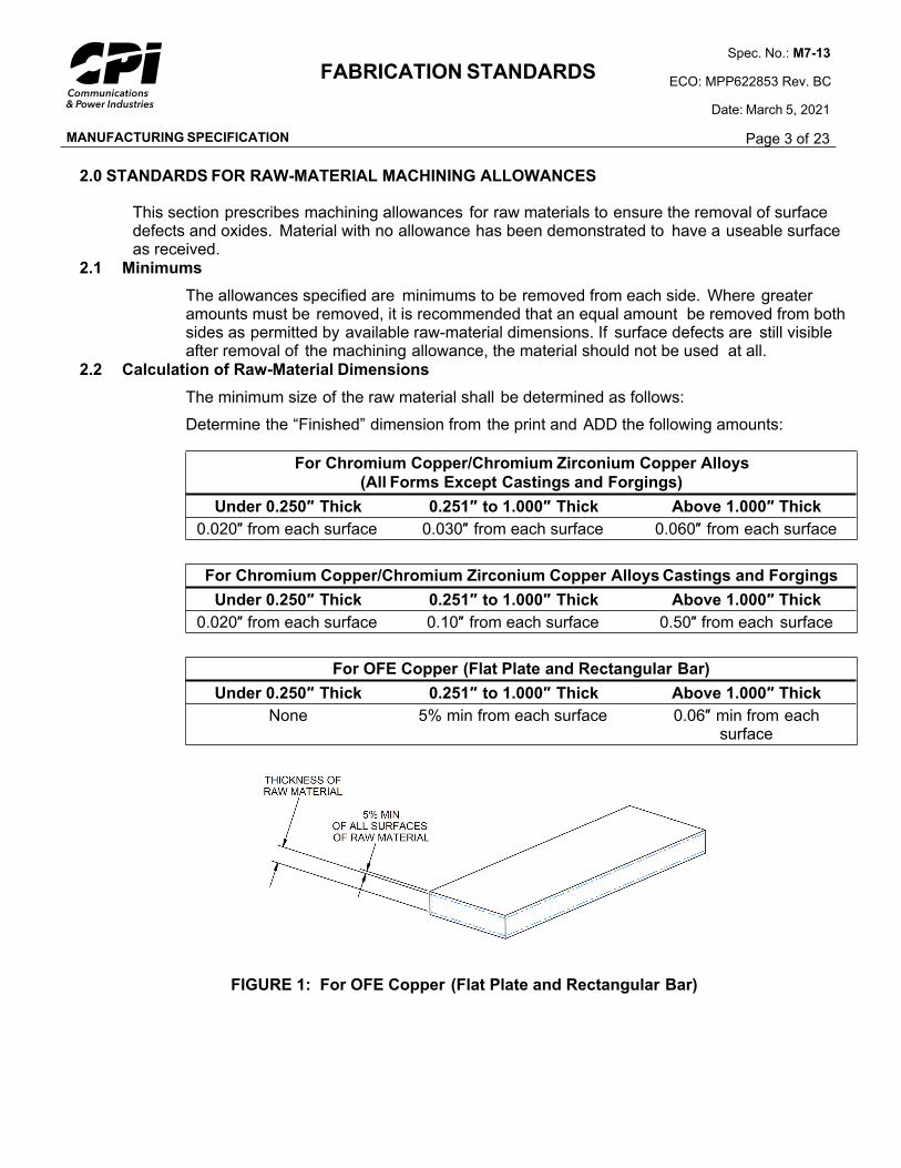
For OFE Copper (Flat Plate and Rectangular Bar)
Under 0.250″ Thick 0.251″ to 1.000″ Thick Above 1.000″ Thick
None 5% min from each surface 0.06″ min from each surface
FIGURE 1: For OFE Copper (Flat Plate and Rectangular Bar)
MANUFACTURING SPECIFICATION
FABRICATION STANDARDSSpec. No.: M7-13
ECO: MPP622853 Rev. BC
Date: March 5, 2021
Page 4 of 23
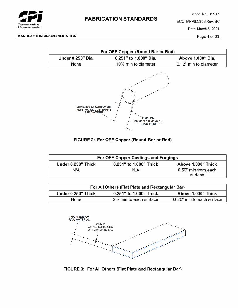
For OFE Copper (Round Bar or Rod)
Under 0.250″ Dia. 0.251″ to 1.000″ Dia. Above 1.000″ Dia.
None 10% min to diameter 0.12″ min to diameter
FIGURE 2: For OFE Copper (Round Bar or Rod)
For OFE Copper Castings and Forgings
Under 0.250″ Thick 0.251″ to 1.000″ Thick Above 1.000″ Thick
N/A N/A 0.50″ min from each surface
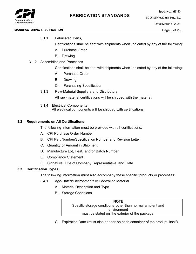
For All Others (Flat Plate and Rectangular Bar)
Under 0.250″ Thick 0.251″ to 1.000″ Thick Above 1.000″ Thick
None 2% min to each surface 0.020″ min to each surface
FIGURE 3: For All Others (Flat Plate and Rectangular Bar)
2% MINOF ALL SURFACESOF RAW MATERIAL

MANUFACTURING SPECIFICATION
FABRICATION STANDARDSSpec. No.: M7-13
ECO: MPP622853 Rev. BC
Date: March 5, 2021
Page 5 of 23
For All Others (Round Bar or Rod)
Under 0.250″ Dia. 0.251″ Dia. to 1.000″ Dia. Above 1.000″ Dia.
None 4% min to diameter 0.040″ min to diameter
FIGURE 4: For All Others (Round Bar or Rod)
2.3 Tubing
The raw-material sizes for the OD of tubing shall be calculated in the same way as the round bar diameter.
The maximum ID of tubing shall be calculated by DEDUCTING the following amounts from the “Finished” dimension:
Under 1.000″ ID Above 1.000″ IDNone 0.040″ min
3.0 CERTIFICATION
This section defines the items requiring certification as specified by CPI and states the minimum information that must accompany the parts or assemblies.
3.1 Delivery or Storage of Certifications
This section defines the instances wherein the Supplier is to include the certification with the shipment. In all cases, the Supplier is to maintain certifications as Quality Records at its facility in accordance with P0-3, “Supplier Quality System Requirements.” Any of the following phrases, or a similar phrase with the same intent, may be used to indicate that certifications must be supplied with shipments:
A. Certification Required
B. Certs. Required
C. Certified Reports Shall Be Provided with Shipment
MANUFACTURING SPECIFICATION
FABRICATION STANDARDSSpec. No.: M7-13
ECO: MPP622853 Rev. BC
Date: March 5, 2021
Page 6 of 23
3.1.1 Fabricated Parts,
Certifications shall be sent with shipments when indicated by any of the following:
A. Purchase Order
B. Drawing
3.1.2 Assemblies and Processes
Certifications shall be sent with shipments when indicated by any of the following:
A. Purchase Order
B. Drawing
C. Purchasing Specification
3.1.3 Raw-Material Suppliers and Distributors
All raw-material certifications will be shipped with the material.
3.1.4 Electrical ComponentsAll electrical components will be shipped with certifications.
3.2 Requirements on All Certifications
The following information must be provided with all certifications:
A. CPI Purchase Order Number
B. CPI Part Number/Specification Number and Revision Letter
C. Quantity or Amount in Shipment
D. Manufacture Lot, Heat, and/or Batch Number
E. Compliance Statement
F. Signature, Title of Company Representative, and Date
3.3 Certification Types
The following information must also accompany these specific products or processes:
3.4.1 Age-Dated/Environmentally Controlled Material
A. Material Description and Type
B. Storage Conditions
NOTE Specific storage conditions other than normal ambient and
environment must be stated on the exterior of the package.
C. Expiration Date (must also appear on each container of the product itself)
MANUFACTURING SPECIFICATION
FABRICATION STANDARDSSpec. No.: M7-13
ECO: MPP622853 Rev. BC
Date: March 5, 2021
Page 7 of 23
3.4.2 Ceramics
A. Material Description
B. Method of Manufacture (i.e., isostatic, extruded, etc.)
3.4.3 Raw Material (When required by CPI Purchasing Specification)
A. CPI Material Purchasing Specifications (i.e., P3-1B, P1-7D, etc.)
B. Size and/or Shape of Material
C. Test Reports (chemical and physical)
3.4.4 Special Processing (Typical processing certifications include plating, priming, heat-treating, ceramic metallizing, brazing, welding, etc.)
A. Total Quantity Processed
B. Definition of Process (CPI specification, MIL specification, or other brief description)
3.4.5 Specific Requirements or Tests (Mechanical, Electrical, Environmental)
Description of the specific item being certified
A. CPI Drawing and Note Number
B. Applicable Specification and Requirement4.0 PACKAGING AND LABELING
4.1 Parts Protection in Packing
Parts shall be packaged for shipment so they are protected from damage and contamination, prevented from nesting and entangling, and easy to unpack. Step 4.1.2B lists several packaging schemes that can be used as an aid. For more detail on packaging items, see Section 1 of M7-35, “Inventory packaging.”
4.1.1 Unacceptable Packing Materials
Dusty and linty materials such as sawdust, shredded newspaper, and excelsior.
No use of tape on parts smaller than 2.0 square inches or diameter.
4.1.2 Suitable Packing Materials
A. Cellulose wadding (Kimpack), corrugated paper board, and expanded plastics (specific notes on drawings concerning packing requirements take precedence.)
MANUFACTURING SPECIFICATION
FABRICATION STANDARDSSpec. No.: M7-13
ECO: MPP622853 Rev. BC
Date: March 5, 2021
Page 8 of 23
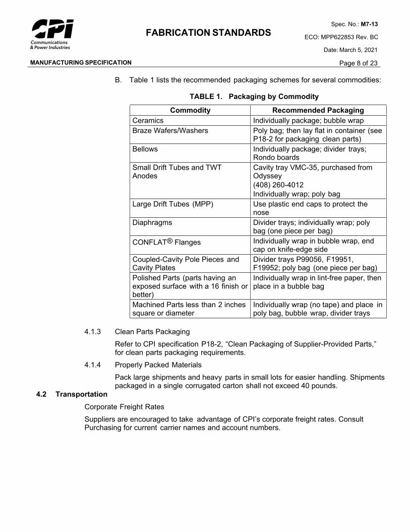
B. Table 1 lists the recommended packaging schemes for several commodities:
TABLE 1. Packaging by Commodity
Commodity Recommended Packaging
Ceramics Individually package; bubble wrap
Braze Wafers/Washers Poly bag; then lay flat in container (see P18-2 for packaging clean parts)
Bellows Individually package; divider trays; Rondo boards
Small Drift Tubes and TWT Anodes
Cavity tray VMC-35, purchased from Odyssey
(408) 260-4012
Individually wrap; poly bag
Large Drift Tubes (MPP) Use plastic end caps to protect the nose
Diaphragms Divider trays; individually wrap; poly bag (one piece per bag)
CONFLAT® Flanges Individually wrap in bubble wrap, end cap on knife-edge side
Coupled-Cavity Pole Pieces and Cavity Plates
Divider trays P99056, F19951, F19952; poly bag (one piece per bag)
Polished Parts (parts having an exposed surface with a 16 finish or better)
Individually wrap in lint-free paper, then place in a bubble bag
Machined Parts less than 2 inches square or diameter
Individually wrap (no tape) and place in poly bag, bubble wrap, divider trays
4.1.3 Clean Parts Packaging
Refer to CPI specification P18-2, “Clean Packaging of Supplier-Provided Parts,” for clean parts packaging requirements.
4.1.4 Properly Packed Materials
Pack large shipments and heavy parts in small lots for easier handling. Shipments packaged in a single corrugated carton shall not exceed 40 pounds.
4.2 Transportation
Corporate Freight Rates
Suppliers are encouraged to take advantage of CPI’s corporate freight rates. Consult Purchasing for current carrier names and account numbers.
MANUFACTURING SPECIFICATION
FABRICATION STANDARDSSpec. No.: M7-13
ECO: MPP622853 Rev. BC
Date: March 5, 2021
Page 9 of 23
4.3 Package Labeling
4.3.1 Label Requirements
Label each package as follows:
A. Name of Supplier
B. CPI Division Purchase Order Number
C. Receiving Area
D. CPI Division Part Number and Revision Letter
E. Quantity (use same unit of measure as stated on purchase order)
F. Other applicable information (i.e., Just-in-Time Delivery labels, EPA requirements, clean parts labels, etc.)
4.3.2 Multiple Container Lots
Lots shipped in more than one container must be sequentially labeled (i.e., Box 1 of 3, Box 2 of 3, etc.)
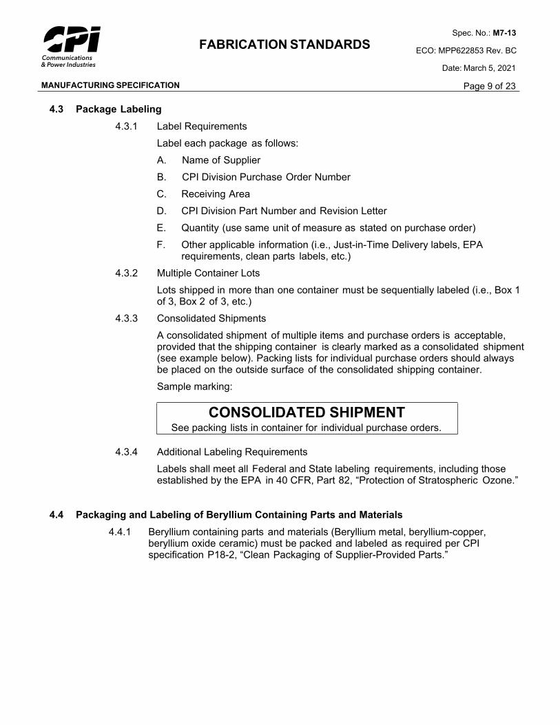
4.3.3 Consolidated Shipments
A consolidated shipment of multiple items and purchase orders is acceptable, provided that the shipping container is clearly marked as a consolidated shipment (see example below). Packing lists for individual purchase orders should always be placed on the outside surface of the consolidated shipping container.
Sample marking:
CONSOLIDATED SHIPMENTSee packing lists in container for individual purchase orders.
4.3.4 Additional Labeling Requirements
Labels shall meet all Federal and State labeling requirements, including those established by the EPA in 40 CFR, Part 82, “Protection of Stratospheric Ozone.”
4.4 Packaging and Labeling of Beryllium Containing Parts and Materials
4.4.1 Beryllium containing parts and materials (Beryllium metal, beryllium-copper, beryllium oxide ceramic) must be packed and labeled as required per CPI specification P18-2, “Clean Packaging of Supplier-Provided Parts.”

MANUFACTURING SPECIFICATION
FABRICATION STANDARDSSpec. No.: M7-13
ECO: MPP622853 Rev. BC
Date: March 5, 2021
Page 10 of 23
5.0 GEOMETRIC DIMENSIONING AND TOLERANCING SYSTEM
Interpret dimensions and tolerances according to the latest revision of ANSI Y14.5, “Dimensions and Tolerancing.”
5.1 Unspecified Tolerance
When the tolerance limit is not specified on the drawing or sketch, the following shall apply:
Decimal: 1 place ±0.12 places ±0.023 places ±0.0054 places ±0.0005
Fraction: ±1/64Angles: ±1°
5.2 Unspecified Finish
The finish requirement for machined surfaces shall be 125 unless otherwise specified.
Flaws are not included in surface finish measurements. The following flaws are not acceptable unless otherwise specified:
Splits, tears, and cracks
Displaced metal, folds (ironed-in or smeared-over scratches and burrs)
Inclusions (imbedded particles—chips, burrs, foreign matter)
Oxide (rust or corrosion)
Seams
The surface finish must not exceed the average value of microinches shown by the symbol
( ).
Unless otherwise specified, the general finish in the title block applies only to machined surfaces.
Commercial stock surface finish is acceptable when “stock” is specified as a dimension.
5.3 Unspecified Flatness
When flatness is not specified, it shall not exceed the values in Table 2 and shall not violate the MMC perfect-form boundary.
MANUFACTURING SPECIFICATION
FABRICATION STANDARDSSpec. No.: M7-13
ECO: MPP622853 Rev. BC
Date: March 5, 2021
Page 11 of 23
TABLE 2: Flatness Tolerance
Surface Finish
Required
Unit Variation
in any Direction
Total Variation
if Length is 1″ or More
63
or better
0.003 in. per in. 0.003 times the longest element of the feature with a maximum of 0.012
64
or rougher
0.005 in. per in. 0.005 times the longest element of the feature with a maximum of 0.020
5.4 Unspecified Cylindricity
When cylindricity is not specified on the drawing, diameters shall be cylindrical within one-half the feature size tolerance and shall not violate the MMC perfect-form boundary.
5.5 Unspecified Perpendicularity
When implied right (90 ) angles are not specified in the drawing, they shall be within ±0 15’ of the intended 90 angle or 0.004 inch per inch maximum error and shall not violate the MMC perfect-form boundary.
5.6 Unspecified Parallelism
When surfaces shown in parallel relationship are not specified on the drawing, they shall be parallel within 0.002 inch per inch of width or length and shall not violate the MMC perfect-form boundary.
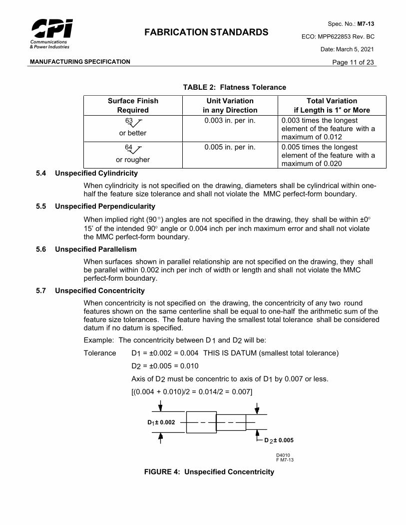
5.7 Unspecified Concentricity
When concentricity is not specified on the drawing, the concentricity of any two round features shown on the same centerline shall be equal to one-half the arithmetic sum of the feature size tolerances. The feature having the smallest total tolerance shall be considered datum if no datum is specified.
Example: The concentricity between D1 and D2 will be:
Tolerance D1 = ±0.002 = 0.004 THIS IS DATUM (smallest total tolerance)
D2 = ±0.005 = 0.010
Axis of D2 must be concentric to axis of D1 by 0.007 or less.
[(0.004 + 0.010)/2 = 0.014/2 = 0.007]
D4010F M7-13
D ± 0.0052
D ± 0.0021
FIGURE 4: Unspecified Concentricity
MANUFACTURING SPECIFICATION
FABRICATION STANDARDSSpec. No.: M7-13
ECO: MPP622853 Rev. BC
Date: March 5, 2021
Page 12 of 23
5.8 Unspecified Position
When positional symmetry is not specified, ( formerly ) features shown as lying on
the centerline of a part (i.e., a slot in a screw head) shall be symmetrical within the total width tolerance of the feature.
5.9 Unspecified Circularity
Diameters that do not have a specified roundness tolerance shall be round within one-half the feature size tolerance but must not extend beyond the MMC perfect-form boundary.
5.10 Unspecified Countersinks
Unless otherwise specified, all countersinks shall be 82 ±5.6.0 TOOLING
Parts contamination can result from contact with some materials commonly used for tooling. Tooling made of brass, bronze, or platinum shall not be used. Cadmium- or zinc-plated tooling shall not be used.
Exception: Parts that are not used inside the vacuum envelope of microwave, power-grid, and X-ray VEDs (or similar devices) are exempt from this requirement. These parts are either made from brass, aluminum, zinc, lead, and plastic or designated by the drawing as not used in the vacuum envelope of the VED.
7.0 CLEANING, PLATING, AND COATING OF SURFACES
All fabricated parts must be received at CPI free of machining lubricants, oils, contaminants, and particles. (The exception to this rule shall be components made from materials that would rust if not protected by an approved rust inhibitor. Materials in this category shall be degreased and coated with an approved rust inhibitor before being packaged for shipment or introduced into the Supplier's stock).
Plating, coating, or other metal finishing to be performed by Suppliers shall be specified on the drawing using military or industry standards. All quality-assurance provisions in the standard shall apply. Processes to be performed within CPI shall refer to the CPI specification.
When a part or assembly drawing specifies plating or coating, dimensions on the drawing are the machined/fabricated dimensions. The part or assembly has been designed to allow for the application of the plating or coating as specified. Any dimensions that apply after plating will be noted separately.
Specified coating thicknesses are the average thickness for the entire part. Normal thickness distribution based on current density is assumed. For example, areas of high-current density, such as sharp edges and outer ends of parts, can have considerably more than the specified coating thickness. Areas of critical thickness will be noted on the drawing. Compliance to critical thickness specifications must be verified and documented.
All threaded holes shall be masked prior to plating or painting to ensure there is no buildup of the plating or paint in the threaded hole.
MANUFACTURING SPECIFICATION
FABRICATION STANDARDSSpec. No.: M7-13
ECO: MPP622853 Rev. BC
Date: March 5, 2021
Page 13 of 23
8.0 BURRS
Burrs adversely affect VED performance by acting as traps for chemical cleaning solutions, serving as “virtual” leaks and as point emission sources in areas of high-electrical potential.
8.1 Definition
A burr is found at the edge of a stamped or machined feature and is defined as a small projection of material that interrupts the normal contour of the plane or surface. (Note that this definition says a burr can only occur at an edge of a feature; anything on the surface is a nodule or particle, etc.)
8.2 Types
Various types of burrs are defined as follows:
An imbedded burr is any burr that has been pressed into the material.
A feather burr is a very fine or thin burr generally less than 0.001-inch thick.
A hanging burr is a burr that is not firmly attached to the workpiece.
A rolled-over burr is a tight burr that is curled over on itself in such a manner that it traps contaminants within itself.
NOTE: ROLLED-OVER AND IMBEDDED BURRS ARE NOT ALLOWED. EMBEDDED PARTICLES ARE NOT ALLOWED.
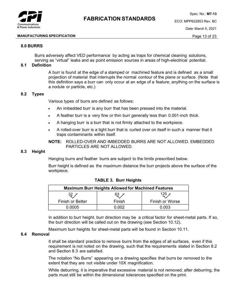
8.3 Height
Hanging burrs and feather burrs are subject to the limits prescribed below.
Burr height is defined as the maximum distance the burr projects above the surface of the workpiece.
TABLE 3. Burr Heights
Maximum Burr Heights Allowed for Machined Features
32
Finish or Better
63
Finish
125
Finish or Worse
0.0005 0.002 0.003
In addition to burr height, burr direction may be a critical factor for sheet-metal parts. If so, the burr direction will be called out on the drawing (see Section 10.12).
Maximum burr heights for sheet-metal parts will be found in Section 10.11. 8.4 Removal
It shall be standard practice to remove burrs from the edges of all surfaces, even if this requirement is not noted on the drawing, such that the requirements stated in Section 8.2 and Section 8.3 are satisfied.
The notation “No Burrs” appearing on a drawing specifies that burrs be removed to the extent that they are not visible under 10X magnification.
While deburring, it is imperative that excessive material is not removed; after deburring, the parts must still be within the dimensional tolerances specified on the print.
MANUFACTURING SPECIFICATION
FABRICATION STANDARDSSpec. No.: M7-13
ECO: MPP622853 Rev. BC
Date: March 5, 2021
Page 14 of 23
The deburring method used must not introduce any contamination, and all loose particles must be removed.
Contamination resulting from embedded particles introduced during the deburring processes can adversely affect the performance of our product. The use of bonded abrasives (i.e., a Cratex stick) that can leave embedded particles is NOT acceptable.
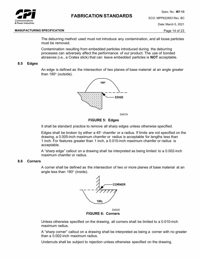
8.5 Edges
An edge is defined as the intersection of two planes of base material at an angle greater
than 180 (outside).
EDGE
180¡
D4019
FIGURE 5: Edges
It shall be standard practice to remove all sharp edges unless otherwise specified.
Edges shall be broken by either a 45 chamfer or a radius. If limits are not specified on the drawing, a 0.005-inch maximum chamfer or radius is acceptable for lengths less than 1 inch. For features greater than 1 inch, a 0.010-inch maximum chamfer or radius is acceptable.
A “sharp edge” callout on a drawing shall be interpreted as being limited to a 0.002-inch maximum chamfer or radius.
8.6 Corners
A corner shall be defined as the intersection of two or more planes of base material at an
angle less than 180 (inside).
CORNER
180¡
D4020
FIGURE 6: Corners
Unless otherwise specified on the drawing, all corners shall be limited to a 0.010-inch maximum radius.
A “sharp corner” callout on a drawing shall be interpreted as being a corner with no greater than a 0.002-inch maximum radius.
Undercuts shall be subject to rejection unless otherwise specified on the drawing.
180
MANUFACTURING SPECIFICATION
FABRICATION STANDARDSSpec. No.: M7-13
ECO: MPP622853 Rev. BC
Date: March 5, 2021
Page 15 of 23
8.7 Sheet Metal
For additional requirements concerning burrs on sheet-metal products, see Section 10.11.9.0 THREADS
All threads, unless otherwise specified on the drawing, shall conform to the unified tabulations and formulations of FED-STD-H28, “Screw Thread Standards for Federal Services.” Unified form threads, American National Form threads, special threads, and unified miniature screw threads shall be defined by the unified system.
9.1 Internal Threads
All internal threads shall be tapped using standard machine screw taps or machined. THREAD-FORMING TOOLS ARE PROHIBITED UNLESS OTHERWISE SPECIFIED as formed threads can trap contaminants. EXCEPTION: Parts that are not used inside the vacuum envelope of vacuum-electron devices are exempt from this requirement. These parts are either made from brass, aluminum, zinc, lead, or plastic or are designated by the drawing as not used in the vacuum envelope of the VED.
9.2 Threaded Holes
All threaded holes shall be countersunk 82 ± 5 to a diameter equal to at least the major diameter of the specified thread. In the case of through-holes, this requirement shall apply to both ends. The countersink diameter shall not exceed 0.020 inch over the major thread diameter.
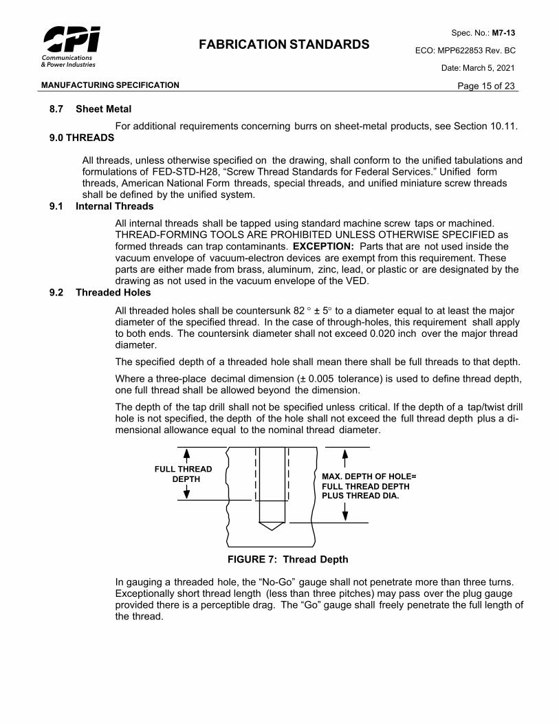
The specified depth of a threaded hole shall mean there shall be full threads to that depth.
Where a three-place decimal dimension (± 0.005 tolerance) is used to define thread depth, one full thread shall be allowed beyond the dimension.
The depth of the tap drill shall not be specified unless critical. If the depth of a tap/twist drill hole is not specified, the depth of the hole shall not exceed the full thread depth plus a di-mensional allowance equal to the nominal thread diameter.
MAX. DEPTH OF HOLE=
FULL THREAD DEPTHPLUS THREAD DIA.
FULL THREAD
DEPTH
FIGURE 7: Thread Depth
In gauging a threaded hole, the “No-Go” gauge shall not penetrate more than three turns. Exceptionally short thread length (less than three pitches) may pass over the plug gauge provided there is a perceptible drag. The “Go” gauge shall freely penetrate the full length of the thread.
MANUFACTURING SPECIFICATION
FABRICATION STANDARDSSpec. No.: M7-13
ECO: MPP622853 Rev. BC
Date: March 5, 2021
Page 16 of 23
9.3 Threaded Parts
The end of all external threads shall be chamfered at 45 ± 5 to the minor diameter.
9.4 Full-Form Threads
The length of fully formed threads is dimensioned. When only one dimension is used to specify the length of threads, it is interpreted to mean the length of fully formed threads, excluding runout. Where a chamfer, not exceeding two pitches in length, exists at the entering end of the thread, it is included in the length of fully formed threads. Figure 5 below shows methods of delineating with no limit on runout.
THREAD LENGTH
X.XXX X.XXX
D4025
FIGURE 8: Thread Length
9.5 Unspecified Thread Class of Fit
TABLE 4: Thread Class
Thread Description Thread Class of Fit
External Threads 2A
Internal Threads 2B
External Threads (Metric) 6G
Internal Threads (Metric) 6H
Threaded Inserts (#3–#8) 2B
Threaded Inserts (>#8) 2B or 3B
10.0 SHEET-METAL PRODUCTS FABRICATION REQUIREMENTS
10.1 Sheet Metal
Sheet metal is considered to be sheet stock that has a nominal thickness of 0.250 (1/4) inch or less.
10.2 Features and Surfaces
Features and surfaces of sheet-metal parts shall be within drawing dimensional limits of size in the unrestrained condition unless otherwise specified.
10.3 Machined Features
Obvious machined features such as countersinks, chamfers, screw threads, and close-tolerance (0.003 inch or less) holes shall conform to the body of this standard.
MANUFACTURING SPECIFICATION
FABRICATION STANDARDSSpec. No.: M7-13
ECO: MPP622853 Rev. BC
Date: March 5, 2021
Page 17 of 23
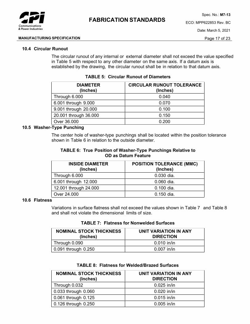
10.4 Circular Runout
The circular runout of any internal or external diameter shall not exceed the value specified in Table 5 with respect to any other diameter on the same axis. If a datum axis is established by the drawing, the circular runout shall be in relation to that datum axis.
TABLE 5: Circular Runout of Diameters
DIAMETER
(Inches)
CIRCULAR RUNOUT TOLERANCE
(Inches)
Through 6.000 0.040
6.001 through 9.000 0.070
9.001 through 20.000 0.100
20.001 through 36.000 0.150
Over 36.000 0.200
10.5 Washer-Type Punching
The center hole of washer-type punchings shall be located within the position tolerance shown in Table 6 in relation to the outside diameter.
TABLE 6: True Position of Washer-Type Punchings Relative to
OD as Datum Feature
INSIDE DIAMETER
(Inches)
POSITION TOLERANCE (MMC)
(Inches)
Through 6.000 0.030 dia.
6.001 through 12.000 0.060 dia.
12.001 through 24.000 0.100 dia.
Over 24.000 0.150 dia.
10.6 Flatness
Variations in surface flatness shall not exceed the values shown in Table 7 and Table 8 and shall not violate the dimensional limits of size.
TABLE 7: Flatness for Nonwelded Surfaces
NOMINAL STOCK THICKNESS
(Inches)
UNIT VARIATION IN ANY
DIRECTION
Through 0.090 0.010 in/in
0.091 through 0.250 0.007 in/in
TABLE 8: Flatness for Welded/Brazed Surfaces
NOMINAL STOCK THICKNESS
(Inches)
UNIT VARIATION IN ANY
DIRECTION
Through 0.032 0.025 in/in
0.033 through 0.060 0.020 in/in
0.061 through 0.125 0.015 in/in
0.126 through 0.250 0.005 in/in
MANUFACTURING SPECIFICATION
FABRICATION STANDARDSSpec. No.: M7-13
ECO: MPP622853 Rev. BC
Date: March 5, 2021
Page 18 of 23
10.7 Parallelism and Perpendicularity
The elements of flat sheet-metal surfaces that are shown as parallel or perpendicular shall
be parallel or perpendicular to each other within 3 . The datum shall be the longest adjacent surface that is parallel or perpendicular to the surface being measured.
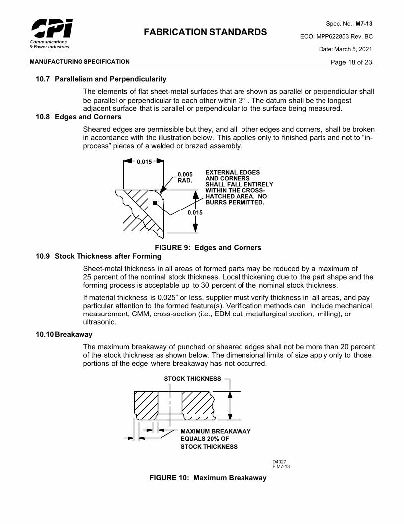
10.8 Edges and Corners
Sheared edges are permissible but they, and all other edges and corners, shall be broken in accordance with the illustration below. This applies only to finished parts and not to “in-process” pieces of a welded or brazed assembly.
0.015
0.005RAD.
EXTERNAL EDGESAND CORNERSSHALL FALL ENTIRELYWITHIN THE CROSS-HATCHED AREA. NOBURRS PERMITTED.
0.015
FIGURE 9: Edges and Corners
10.9 Stock Thickness after Forming
Sheet-metal thickness in all areas of formed parts may be reduced by a maximum of 25 percent of the nominal stock thickness. Local thickening due to the part shape and the forming process is acceptable up to 30 percent of the nominal stock thickness.
If material thickness is 0.025” or less, supplier must verify thickness in all areas, and pay particular attention to the formed feature(s). Verification methods can include mechanical measurement, CMM, cross-section (i.e., EDM cut, metallurgical section, milling), or ultrasonic.
10.10Breakaway
The maximum breakaway of punched or sheared edges shall not be more than 20 percent of the stock thickness as shown below. The dimensional limits of size apply only to those portions of the edge where breakaway has not occurred.
D4027F M7-13
STOCK THICKNESS
MAXIMUM BREAKAWAY
EQUALS 20% OF
STOCK THICKNESS
FIGURE 10: Maximum Breakaway
MANUFACTURING SPECIFICATION
FABRICATION STANDARDSSpec. No.: M7-13
ECO: MPP622853 Rev. BC
Date: March 5, 2021
Page 19 of 23
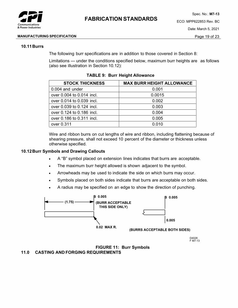
10.11Burrs
The following burr specifications are in addition to those covered in Section 8:
Limitations — under the conditions specified below, maximum burr heights are as follows (also see illustration in Section 10.12):
TABLE 9: Burr Height Allowance
STOCK THICKNESS MAX BURR HEIGHT ALLOWANCE
0.004 and under 0.001
over 0.004 to 0.014 incl. 0.0015
over 0.014 to 0.039 incl. 0.002
over 0.039 to 0.124 incl. 0.003
over 0.124 to 0.186 incl. 0.004
over 0.186 to 0.311 incl. 0.005
over 0.311 0.010
Wire and ribbon burrs on cut lengths of wire and ribbon, including flattening because of shearing pressure, shall not exceed 10 percent of the diameter or thickness unless otherwise specified.
10.12Burr Symbols and Drawing Callouts
A “B” symbol placed on extension lines indicates that burrs are acceptable.
The maximum burr height allowed is shown adjacent to the symbol.
Arrowheads may be used to indicate the side on which burrs may occur.
Symbols placed on both sides indicate that burrs are acceptable on both sides.
A radius may be specified on an edge to show the direction of punching.
D4028F M7-13
B 0.005
0.005
(BURRS ACCEPTABLE BOTH SIDES)
B 0.005
0.02 MAX R.
(1.75) (BURR ACCEPTABLE
THIS SIDE ONLY)
FIGURE 11: Burr Symbols
11.0 CASTING AND FORGING REQUIREMENTS
MANUFACTURING SPECIFICATION
FABRICATION STANDARDSSpec. No.: M7-13
ECO: MPP622853 Rev. BC
Date: March 5, 2021
Page 20 of 23
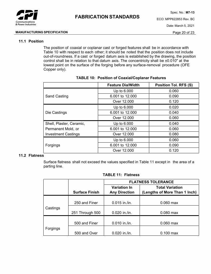
11.1 Position
The position of coaxial or coplanar cast or forged features shall be in accordance with Table 10 with respect to each other; it should be noted that the position does not include out-of-roundness. If a cast or forged datum axis is established by the drawing, the position control shall be in relation to that datum axis. The concentricity shall be ±0.010″ at the lowest point on the surface of the forging before any surface-removal procedure (OFE Copper only).
TABLE 10: Position of Coaxial/Coplanar Features
Feature Dia/Width Position Tol. RFS (S)
Up to 6.000 0.060
Sand Casting 6.001 to 12.000 0.090
Over 12.000 0.120
Up to 6.000 0.020
Die Castings 6.001 to 12.000 0.040
Over 12.000 0.060
Shell, Plaster, Ceramic, Up to 6.000 0.040
Permanent Mold, or 6.001 to 12.000 0.060
Investment Castings Over 12.000 0.080
Up to 6.000 0.060
Forgings 6.001 to 12.000 0.090
Over 12.000 0.120
11.2 Flatness
Surface flatness shall not exceed the values specified in Table 11 except in the area of a parting line.
TABLE 11: Flatness
FLATNESS TOLERANCE
Surface Finish
Variation In
Any Direction
Total Variation
(Lengths of More Than 1 Inch)
250 and Finer 0.015 in./in. 0.060 max
Castings
251 Through 500 0.020 in./in. 0.080 max
500 and Finer 0.010 in./in. 0.060 max
Forgings
500 and Over 0.020 in./in. 0.100 max
MANUFACTURING SPECIFICATION
FABRICATION STANDARDSSpec. No.: M7-13
ECO: MPP622853 Rev. BC
Date: March 5, 2021
Page 21 of 23
11.3 Cleanup
Gates, risers, flash, runners, and parting lines on surfaces not subject to subsequent machining shall be trimmed and blended smooth with the part contour. Surfaces subject to subsequent machining shall be finished according to normal industry practice.
11.4 Mismatch
Parting-line mismatch for forgings shall not exceed 0.05 inch maximum. Mismatch is defined as a defect resulting from die misalignment, producing an offset on the surfaces of the forging at the parting line. The mismatch of castings shall be contained within the applicable position requirements.
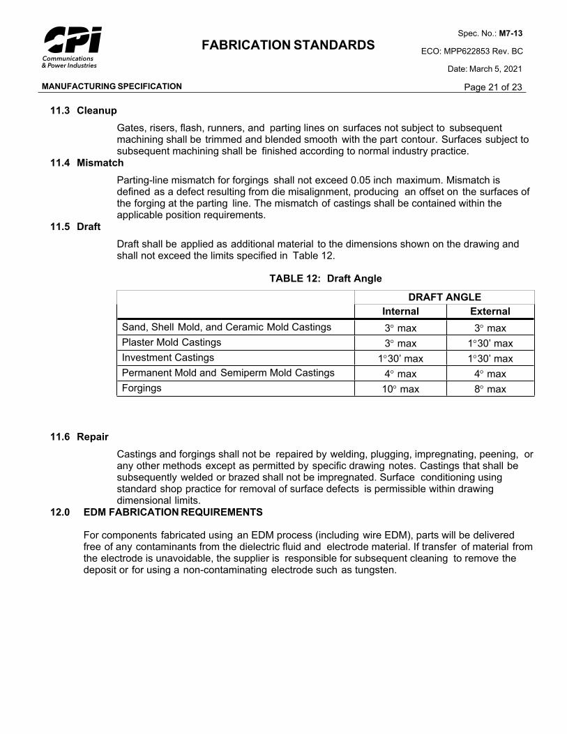
11.5 Draft
Draft shall be applied as additional material to the dimensions shown on the drawing and shall not exceed the limits specified in Table 12.
TABLE 12: Draft Angle
DRAFT ANGLE
Internal External
Sand, Shell Mold, and Ceramic Mold Castings 3 max 3 max
Plaster Mold Castings 3 max 130’ max
Investment Castings 130’ max 130’ max
Permanent Mold and Semiperm Mold Castings 4 max 4 max
Forgings 10 max 8 max
11.6 Repair
Castings and forgings shall not be repaired by welding, plugging, impregnating, peening, or any other methods except as permitted by specific drawing notes. Castings that shall be subsequently welded or brazed shall not be impregnated. Surface conditioning using standard shop practice for removal of surface defects is permissible within drawing dimensional limits.
12.0 EDM FABRICATION REQUIREMENTS
For components fabricated using an EDM process (including wire EDM), parts will be delivered free of any contaminants from the dielectric fluid and electrode material. If transfer of material from the electrode is unavoidable, the supplier is responsible for subsequent cleaning to remove the deposit or for using a non-contaminating electrode such as tungsten.
MANUFACTURING SPECIFICATION
FABRICATION STANDARDSSpec. No.: M7-13
ECO: MPP622853 Rev. BC
Date: March 5, 2021
Page 22 of 23
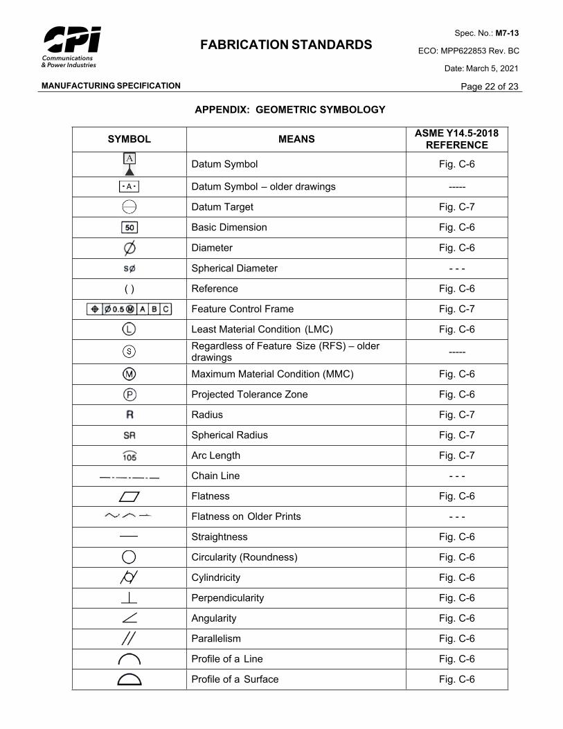
APPENDIX: GEOMETRIC SYMBOLOGY
SYMBOL MEANSASME Y14.5-2018
REFERENCE
Datum Symbol Fig. C-6
Datum Symbol – older drawings -----
Datum Target Fig. C-7
Basic Dimension Fig. C-6
Diameter Fig. C-6
Spherical Diameter - - -
( ) Reference Fig. C-6
Feature Control Frame Fig. C-7
Least Material Condition (LMC) Fig. C-6
Regardless of Feature Size (RFS) – older drawings
-----
Maximum Material Condition (MMC) Fig. C-6
Projected Tolerance Zone Fig. C-6
Radius Fig. C-7
Spherical Radius Fig. C-7
Arc Length Fig. C-7
Chain Line - - -
Flatness Fig. C-6
Flatness on Older Prints - - -
Straightness Fig. C-6
Circularity (Roundness) Fig. C-6
Cylindricity Fig. C-6
Perpendicularity Fig. C-6
Angularity Fig. C-6
Parallelism Fig. C-6
Profile of a Line Fig. C-6
Profile of a Surface Fig. C-6
MANUFACTURING SPECIFICATION
FABRICATION STANDARDSSpec. No.: M7-13
ECO: MPP622853 Rev. BC
Date: March 5, 2021
Page 23 of 23
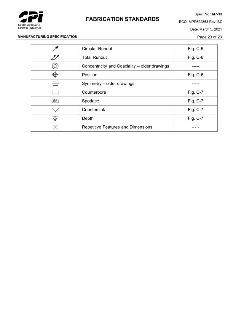
Circular Runout Fig. C-6
Total Runout Fig. C-6
Concentricity and Coaxiality – older drawings -----
Position Fig. C-6
Symmetry – older drawings -----
Counterbore Fig. C-7
Spotface Fig. C-7
Countersink Fig. C-7
Depth Fig. C-7
Repetitive Features and Dimensions - - -


![Illuminating OpenMP + MPI Performance€¦ · cpi-mpi.c:48 cpi-mpi.c:84 cpi-mpi.c:109 cpi-mpi.c:97 1.0% cpi-mpi [program] main main [OpenMP region O] MPI Finalize MPI Reduce Showing](https://img.pdfslide.us/doc/110x75/6022cc2b9a65990f6b41506f/illuminating-openmp-mpi-performance-cpi-mpic48-cpi-mpic84-cpi-mpic109-cpi-mpic97.jpg)