Embed Size (px)
Citation preview
1.0 Introduction
The QShifter is our latest high performance creation for quick shifting. It is a "Strain Gauge" sensor type that, thanks to own electronic and manufacturing tricks, guarantees reliable and long lasting performances. This product is intended for use on a closed circuit only. It's not homologated for road use. The manufacturer of this product is not liable for any kind of damage or injury deriving to the operator, vehicle, or to third parties from the use of this product.
DISCLAIMERS
• System setup must always be done with bike stop and on stands.
• A wrong setting could affect, partially or fully, the system effectiveness damaging the gearbox.
• System setting is responsibility of the user and not of the manufacturer. Take care to sensor fixing to avoid it unscrew or interfere with other parts of the bike.
• The use of this product is at the total discretion of the private parties.
• The manufacturer of this product is not liable for any kind of damage or injury deriving to the operator, vehicle, or to third parties from the use of the product.
• Each system modification, both hardware and software and harness or single components, could affect the system functionality with potential damage or injury caused to the operator, vehicle, or to third parts and delete the product warranty.
• Installation must be done carefully following these instructions. It’s strongly recommended to test the product and the bike after the installation.
• Installation is a very critical operation for system effectiveness. Be sure that it is done by competent and specialized personnel.
1.0 Introduzione
QShifter è la nostra proposta di cambio elettronico. E’ formato da un sensore di tipo "Strain Gauge" che, grazie all'elettronica ed alle tecniche costruttive impiegate, garantisce prestazioni affidabili e durature nel tempo. E’ un prodotto solo per uso pista. Non è omologato per uso stradale. L’azienda non si assume alcuna responsabilità per uso improprio né per danni eventualmente causati a terzi, al veicolo e al pilota.
AVVERTENZE
• L’impostazione del sistema deve essere sempre fatta a moto ferma sul cavalletto.
• Un’errata regolazione potrebbe rendere il sistema del tutto o in parte inefficace comportando rotture degli ingranaggi del cambio.
• La corretta impostazione del sistema è responsabilità dell’utilizzatore e non del fabbricante. Porre particolare attenzione al fissaggio del sistema al fine di evitare che si sviti o che vada ad interferire con altre parti in movimento.
• L’impiego di tale sistema è a discrezione dell’utilizzatore.
• L’azienda non si assume alcuna responsabilità per uso improprio né per danni eventualmente causati a terzi, al Ogni modifica al sistema, sia hardware che software che ai cablaggi o componenti singoli può influenzare il corretto funzionamento del sistema, con danni al pilota, al mezzo o a terzi, e far decadere la garanzia del prodotto.
• L’installazione va effettuata seguendo attentamente le presenti istruzioni. E' fortemente raccomandato testare il prodotto e la moto dopo l'installazione.
• Il montaggio è un’operazione molto critica per il funzionamento del sistema. Accertarsi che venga eseguito da personale specializzato.
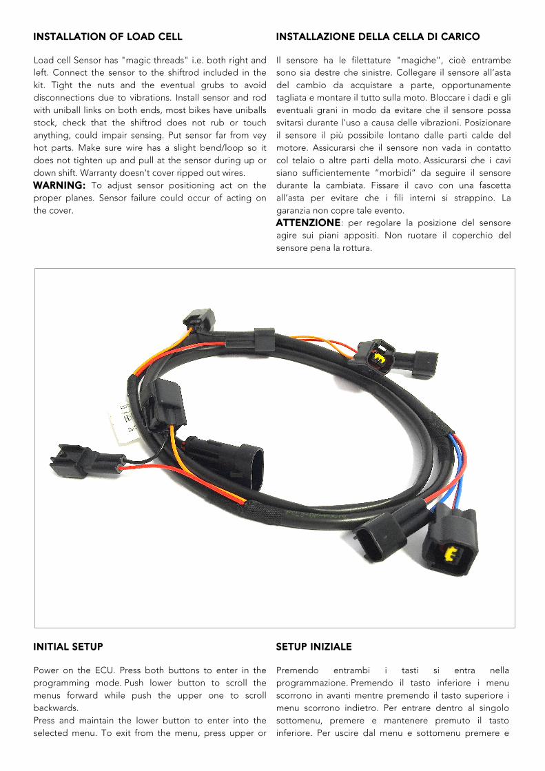
INSTALLATION OF LOAD CELL
Load cell Sensor has "magic threads" i.e. both right and left. Connect the sensor to the shiftrod included in the kit. Tight the nuts and the eventual grubs to avoid disconnections due to vibrations. Install sensor and rod with uniball links on both ends, most bikes have uniballs stock, check that the shiftrod does not rub or touch anything, could impair sensing. Put sensor far from vey hot parts. Make sure wire has a slight bend/loop so it does not tighten up and pull at the sensor during up or down shift. Warranty doesn't cover ripped out wires. WARNING: To adjust sensor positioning act on the proper planes. Sensor failure could occur of acting on the cover.
INSTALLAZIONE DELLA CELLA DI CARICO
Il sensore ha le filettature "magiche", cioè entrambe sono sia destre che sinistre. Collegare il sensore all’asta del cambio da acquistare a parte, opportunamente tagliata e montare il tutto sulla moto. Bloccare i dadi e gli eventuali grani in modo da evitare che il sensore possa svitarsi durante l'uso a causa delle vibrazioni. Posizionare il sensore il più possibile lontano dalle parti calde del motore. Assicurarsi che il sensore non vada in contatto col telaio o altre parti della moto. Assicurarsi che i cavi siano sufficientemente “morbidi” da seguire il sensore durante la cambiata. Fissare il cavo con una fascetta all’asta per evitare che i fili interni si strappino. La garanzia non copre tale evento. ATTENZIONE: per regolare la posizione del sensore agire sui piani appositi. Non ruotare il coperchio del sensore pena la rottura.
INITIAL SETUP
Power on the ECU. Press both buttons to enter in the programming mode. Push lower button to scroll the menus forward while push the upper one to scroll backwards. Press and maintain the lower button to enter into the selected menu. To exit from the menu, press upper or
SETUP INIZIALE
Premendo entrambi i tasti si entra nella programmazione. Premendo il tasto inferiore i menu scorrono in avanti mentre premendo il tasto superiore i menu scorrono indietro. Per entrare dentro al singolo sottomenu, premere e mantenere premuto il tasto inferiore. Per uscire dal menu e sottomenu premere e
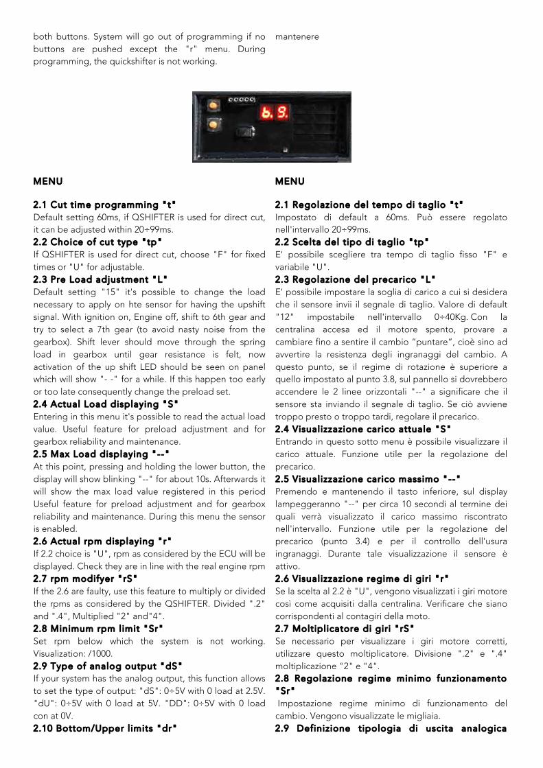
both buttons. System will go out of programming if no buttons are pushed except the "r" menu. During programming, the quickshifter is not working.
mantenere
MENU
2.1 Cut t ime programming "t" Default setting 60ms, if QSHIFTER is used for direct cut, it can be adjusted within 20÷99ms. 2.2 Choice of cut type "tp" If QSHIFTER is used for direct cut, choose "F" for fixed times or "U" for adjustable. 2.3 Pre Load adjustment "L" Default setting "15" it's possible to change the load necessary to apply on hte sensor for having the upshift signal. With ignition on, Engine off, shift to 6th gear and try to select a 7th gear (to avoid nasty noise from the gearbox). Shift lever should move through the spring load in gearbox until gear resistance is felt, now activation of the up shift LED should be seen on panel which will show "- -" for a while. If this happen too early or too late consequently change the preload set. 2.4 Actual Load displaying "S" Entering in this menu it's possible to read the actual load value. Useful feature for preload adjustment and for gearbox reliability and maintenance. 2.5 Max Load displaying "--" At this point, pressing and holding the lower button, the display will show blinking "--" for about 10s. Afterwards it will show the max load value registered in this period Useful feature for preload adjustment and for gearbox reliability and maintenance. During this menu the sensor is enabled. 2.6 Actual rpm displaying "r" If 2.2 choice is "U", rpm as considered by the ECU will be displayed. Check they are in line with the real engine rpm 2.7 rpm modifyer "rS" If the 2.6 are faulty, use this feature to multiply or divided the rpms as considered by the QSHIFTER. Divided ".2" and ".4", Multiplied "2" and"4". 2.8 Minimum rpm limit "Sr" Set rpm below which the system is not working. Visualization: /1000. 2.9 Type of analog output "dS" If your system has the analog output, this function allows to set the type of output: "dS": 0÷5V with 0 load at 2.5V. "dU": 0÷5V with 0 load at 5V. "DD": 0÷5V with 0 load con at 0V. 2.10 Bottom/Upper l imits "dr"
MENU
2.1 Regolazione del tempo di taglio "t" Impostato di default a 60ms. Può essere regolato nell'intervallo 20÷99ms. 2.2 Scelta del t ipo di taglio "tp" E' possibile scegliere tra tempo di taglio fisso "F" e variabile "U". 2.3 Regolazione del precarico "L" E' possibile impostare la soglia di carico a cui si desidera che il sensore invii il segnale di taglio. Valore di default "12" impostabile nell'intervallo 0÷40Kg. Con la centralina accesa ed il motore spento, provare a cambiare fino a sentire il cambio “puntare”, cioè sino ad avvertire la resistenza degli ingranaggi del cambio. A questo punto, se il regime di rotazione è superiore a quello impostato al punto 3.8, sul pannello si dovrebbero accendere le 2 linee orizzontali "--" a significare che il sensore sta inviando il segnale di taglio. Se ciò avviene troppo presto o troppo tardi, regolare il precarico. 2.4 Visualizzazione carico attuale "S" Entrando in questo sotto menu è possibile visualizzare il carico attuale. Funzione utile per la regolazione del precarico. 2.5 Visualizzazione carico massimo "--" Premendo e mantenendo il tasto inferiore, sul display lampeggeranno "--" per circa 10 secondi al termine dei quali verrà visualizzato il carico massimo riscontrato nell'intervallo. Funzione utile per la regolazione del precarico (punto 3.4) e per il controllo dell'usura ingranaggi. Durante tale visualizzazione il sensore è attivo. 2.6 Visualizzazione regime di gir i "r" Se la scelta al 2.2 è "U", vengono visualizzati i giri motore così come acquisiti dalla centralina. Verificare che siano corrispondenti al contagiri della moto. 2.7 Moltiplicatore di gir i "rS" Se necessario per visualizzare i giri motore corretti, utilizzare questo moltiplicatore. Divisione ".2" e ".4" moltiplicazione "2" e "4". 2.8 Regolazione regime minimo funzionamento "Sr" Impostazione regime minimo di funzionamento del cambio. Vengono visualizzate le migliaia. 2.9 Definizione tipologia di uscita analogica

If your system has the analog output, set "5"=±50Kg, "10"=±100Kg. 2.11 Pushing/Pull ing"CE" "C" Pushing o "E" Pulling. 2.12 Smoothness "rr" If you chose for dynamic cut (par 2.2), higher values means smoothness increase. Initially set the ideal upshift rpm. Visualization: /1000
"dS" Se l'SGRACE è dotato di uscita analogica è possibile definirne gli intervalli: "dC": 0÷5V con lo 0 nel mezzo. "dU":0÷5Vconlo0a5V."dd":0÷5Vconlo0a0V. 2.10 Regolazione fondoscala "dr" Se richiesta la versione con uscita analogica, permette di definire la soglia massima del carico. "5"=±50Kg, "10"=±100Kg. 2.11 Regolazione verso di lavoro "CE" E' possibile impostare il verso di lavoro in "C" compressione o "E" estensione. 2.12 Regolazione dolcezza intervento "rr" Se si sceglie il taglio dinamico (par 2.2), più è alto e maggiore sarà la dolcezza di intervento. Impostare inizialmente il regime ideale di cambiata. Vengono visualizzate le migliaia.
CONNECTIONS OF PLUG&PLAY HARNESS
Connect the proper harness you find in the kit to ignition/injection (depends on bike model). Connect Black wire to the battery ground.
COLLEGAMENTO DEL CABLAGGIO OF PLUG&PLAY
Collegare alle bobine il cablaggio fornito al momento dell’ordine, verificando che i fili rossi siano collegati al filo +12 che arriva a cisacuna bobina. In caso contrario contattare l’assistenza. Collegare il filo nero a massa
START After powering, the ECU makes a general check and, if passed, the display will show the firmware version. WARNING: don’t act on the sensor till this procedure has finished. Whenever the pre load threshold is passed (par. 2.3), the display will show "--". In case of failure, on the display will appear an "E" followed by a number. Give this code to the assistance.
ACCENSIONE All'accensione la centralina effettua un check e, se superato, il display indica per 2 secondi la versione del firmware installato. ATTENZIONE: Non agire sul sensore finchè il display non termina la sequenza di cui sopra. Ogni volta che viene superata la soglia di precarico impostata "L" (paragrafo 2.3) nel display indicherà. "--" . In caso di rotture sul display comparirà un'indicazione "E" seguita da un numero. Comunicare questo codice all'assistenza.
GRIPONE is a trademark owned by GUBELLINI s.a.s. di Diego Gubell ini & C. - Via Fiorentina 3508/H 40059
Medicina (BO) ITALY www.gripone.com - [email protected]