Embed Size (px)
Citation preview

10 IEEE TRANSACTIONS ON SOFTWARE ENGINEERING. VOL. 15. NO. I. JANUARY 1989
A Modified Priority Based Probe Algorithm for D istributed Deadlock Detection and Resolution
ALOK N. CHOUDHARY, STUDENT MEMBER, IEEE, WALTER H. KOHLER, SENIOR MEMBER, IEEE, JOHN A. STANKOVIC, SENIOR MEMBER, IEEE, AND DON TOWSLEY, MEMBER, IEEE
Abstract-This paper presents a modified priority based probe al- gorithm for deadlock detection and resolution in distributed database systems. The original priority based probe algorithm was presented by Sinha and Natarajan based on work by Chandy, Misra, and Haas. Various examples are used to show that the original priority based al- gorithm either fails to detect deadlocks or reports deadlocks which do not exist in many situations. A modified algorithm which eliminates these problems is proposed. This algorithm has been tested through simulation and appears to be error free. Finally, the performance of the modified algorithm is briefly discussed.
Index Terms-Concurrency control, deadlock detection, distributed database.
I. INTRODUCTION
T HIS paper presents a modified priority based probe algorithm for deadlock detection and resolution in
distributed database systems. The original priority based probe algorithm was presented by Sinha and Natarajan in [9] based on work by Chandy, Misra, and Haas [3], [4]. Sinha and Natarajan [9] assigned priorities to transactions and used the priorities to reduce the number of probe mes- sages that are forwarded. Two variations of the algorithm were discussed: a basic algorithm to detect deadlocks when only exclusive lock requests by transactions are al- lowed and an extended algorithm when shared and mul- tiple lock requests are allowed. Sinha and Natarajan did not implement the algorithm, nor prove its correctness.
In this paper we show that in many situations Sinha and Natarajan’s algorithm either fails to detect a deadlock cycle or detects a nonexistent (false) deadlock. We also explain why such situations arise and modify their algo- rithm in order to make it work correctly. The final result is a refined priority based probe algorithm to detect and resolve distributed deadlocks. We have extensively tested
Manuscript received July 31, 1986; revised December 30, 1987. This work was supported by the National Science Foundation under Grant SDB- 8418216 and by the Naval Underwater Systems Center under Contract NOO140-84-M-WM07.
A. N. Choudhary was with the Department of Electrical and Computer Engineering, University of Massachusetts, Amherst, MA 01003. He is now with the Computer Systems Group, University of Illinois at Urbana-Cham- paign, Urbana, IL 61801.
W. H. Kohler is with Digital Equipment Corporation, Marlboro, MA 01752.
J. A. Stankovic and D. Towsley are with the Department of Computer and Information Science, University of Massachusetts, Amherst, MA 01003.
IEEE Log Number 8824597.
this algorithm through simulation without finding any er- rors.
The rest of this paper is organized as follows. The dis- tributed database model is briefly discussed in Section II. For a detailed description of the database model and the original algorithms the reader is referred to [9]. Section III contains examples illustrating those situations in which the original algorithm either fails to detect deadlocks or detects false deadlocks. Modifications to eliminate these problems are suggested with each example. Our modified probe algorithm is then presented in Section IV. The tests performed on our algorithm are described in Section V. The impact of the modifications on the performance of the algorithm is also discussed in Section V. Finally, Section VI summarizes the paper.
II. THE DISTRIBUTED DATABASE SYSTEM MODEL
A distributed database system is modeled as a collec- tion of sites (or nodes) which communicate through mes- sages. The messages arrive at a destination site in the same order in which they were sent from a source site. Mes- sages are neither lost nor duplicated and are transmitted error-free. See Sinha and Natarajan [9] and Chandy, Misra, and Haas [3], [4] for further details.
Transactions execute concurrently in some globally se- rializable order [ 11, [2]. Each site has many data items which are accessed by transactions. Each data item is managed by a data manager which has the exclusive right to operate on it. Transactions use the two phase locking protocol (2PL) to access data items [6]. If a transaction wants to lock a data item, it must send a lock request to the data manager managing that data item. A data man- ager grants a lock request on a data item if it is free (un- locked), otherwise it places the request in a queue, called the Request-Q. A transaction can only access a data item after it has acquired a lock on the data item. A transaction which has obtained a lock on a data item is called the holder of the data item, and a transaction waiting in the queue for a lock is called a requester. If shared locks are allowed then there may be more than one holder of a data item. However we focus only on the basic algorithm by Sinha and Natarajan which assumes that transactions only request exclusive locks. Although a data manager may manage many data items, it is assumed that a data man- ager manages only one data item [9] in order to simplify the understanding of the algorithm.
0098-5589/89/0100-OOlO$Ol .OO 0 1989 IEEE

CHOUDHARY er al.: ALGORITHM FOR DISTRIBUTED DEADLOCK DETECTION AND RESOLUTION 11
A transaction can be in one of two states: active or wait. If a transaction has a lock request pending then it is in the wait state, otherwise it is active. A transaction changes its state from active to wait if its lock request cannot be granted. Once a transaction enters the wait state, it cannot request more locks until all of its pending requests are satisfied.
In Sinha and Natarajan’s algorithm, transactions are as- signed priorities where each transaction has a distinct priority. We use the following notation to denote the priority ordering. For two transactions Tj and q, Prior- ity ( Ti) > Priority ( Tj) iff i < j. This will be denoted as Ti > 7;.
III. ERRORS AND DEFICIENCIES
In this section we discuss the cases in which the algo- rithm presented by Sinha and Natarajan [9] either fails to detect a deadlock cycle or detects a false deadlock (a deadlock which does not exist). We also suggest correc- tions to the algorithm which will eliminate these prob- lems. For the convenience of the reader, the basic algo- rithm [9, pp. 69-701 is included in the Appendix. However, the reader is refered to [9] for a detailed de- scription of this algorithm.
There are three basic deficiencies in Sinha and Natara- jan’s algorithm. First, some deadlocks are not detected because probes are initiated and transmitted only once. Second, there are numerous instances when the algorithm detects false deadlocks or fails to detect some deadlocks because it overlocks the possibility that transactions may wait transitively on a deadlock cycle. Third, there are times when the algorithm detects false deadlocks because transactions and data managers save old probes.
In order to understand the problems with the Sinha and Natarajan algorithm and the new algorithm, we introduce the concept of an antagonist ic conf7ict [9].
Dejinition 1: An antagonistic conflict occurs between two transactions if one transaction (called the holder) locks a data item and the other transaction with a higher priority (called the requester) requests that data item. The requester is said to face an antagonistic conflict.
A deadlock is detected by circulating a message, called the probe, through the deadlock cycle. The occurrence of an antagonistic conflict at a data item triggers the initia- tion of a probe. A timeout period can also be introduced to delay the initiation of the algorithm. A probe is an or- dered pair (initiator, junior), where initiator denotes the requester which faced an antagonistic conflict and trig- gered the deadlock detection computation. The element junior denotes the transaction with the lowest priority from among the transactions traversed by the probe.
A data manager sends a probe only to the transaction holding its data, while a transaction sends a probe only to the data manager from which it is waiting to receive a lock grant.
The notation
Tj x, lj . H
means that transaction Ti is waiting for a data item X,, presently held by transaction 7;. The arc between 7; and Tj simply denotes the wait-for relationship. Note that T, does not communicate with q directly. T; sends its request to the data manager managing data item X,, denoted as DM(X,). If T > q when DM(X,) initiates a probe (K, Tj) and sends it to q. Furthermore, DM(Xk) forwards each probe (initiator, junior) it receives from T; to Tj if initiator > Tj.
Before we proceed with the different examples of how Sinha and Natarajan’s algorithm fails, we provide the fol- lowing concise, high level description of their algorithm. The algorithm consists of two parts. The first part is con- cerned with the detection of the deadlock through the propagation of probes. Throughout this phase, transac- tions may be required to store some of these probes. The second part of the algorithm is concerned with resolving a deadlock. This includes first notifying the lowest prior- ity transaction within the cycle that it will be the abort victim and a subsequent phase to remove unnecessary probes stored by other transactions in the cycle. This last phase is initiated by the deadlock victim through the prop- agation of a special clean message. Once again, we refer the reader to [9] for complete details of the algorithm.
A. Undetected Deadlocks In this subsection, we describe conditions under which
a deadlock cycle will not be detected by the Sinha and Natarajan algorithm. We describe how the algorithm can be modified to avoid this problem.
Consider the example shown in Fig. l(a). Assume that DM( Xi ) initiated a probe ( T, , T5) that propagated to T,, then to T4 and finally to T3. Transactions T,, T4, and T3 each store the probe ( T,, T5) in their respective probe_Q’s. Now suppose T3 commits and releases its locks. If T2 is first in the request-Q it will be granted the lock on X3. ’ This situation is shown in Fig. l(b). Now, if T2 requests a lock for a data item presently held by T,, say X4 as shown in Fig. l(c) using a dashed line, a dead- lock cycle will be formed. According to Sinha and Nata- rajan’s algorithm, this deadlock will never be detected. DM( X4) will not initiate a probe because T3 does not face an antagonistic conflict. Even if it faced an antagonistic conflict and initiated a probe, the probe would stop at T1 because TI is the highest priority transaction in the cycle. The probe ( T, , T, ), the only probe which can potentially detect this deadlock cycle, was not and will never be propagated to T2.
The following must be added to part A. 1 of Sinha and Natarajan’s algorithm [9] (see Appendix).
c) When a transaction completes or aborts it re- leases its locks. The data manager associated with each released data item assigns the lock for the data item to some transaction waiting for that data item (if one exists). Each data manager then requests all
‘The situation is possible no matter what scheme is used for granting a lock if there is more than one transaction waiting.
12 IEEE TRANSACTIONS O N SOFTWARE ENGINEERING. VOL. 15. NO. I. JANUARY 1989
(a) (b) Fig. 1. An undetected deadlock. (a) Initial state. (b) State after release by
T3. (c) Resulting undetected deadlock.
remaining transactions waiting on the new lock to transmit their complete probe-Q’s to itself (The identities of these transactions are obtained from the data manager’s request-Q.) The data manager for- wards each received probe (initiator, junior) to the new holder of the lock for which initiator exceeds the priority of the new holder.
Let us return to the example in Fig. 1. At the time that T, completes, it releases its locks and DM( Xs ) grants T2 the lock on Xs. DM( X,) then requests all of the probes in T4’s probe-Q. Transaction T4 sends probe ( T, , T5) to DM( X, ) which DM( Xs ) in turn transfers to T2. There- fore, when the deadlock cycle is formed in Fig. l(c), T2 will send the probe ( T, , T, ) to DM( X4) and conse- quently, DM( X4) will detect the deadlock cycle.
Similar examples can be constructed such that a dead- lock will form which will not be detected following the abortion of a transaction. Consequently, the above actions must also be performed when transactions abort.
B. False Deadlocks In addition to the above mentioned problems, the al-
gorithm detects false deadlocks. “False deadlock” does not have a universal definition. However, the most widely accepted definition of a false deadlock is “a deadlock which does not exist when reported by an algorithm. ” We present two examples that illustrate cases where false deadlocks are detected due to external (or transitive) probes and old probes.
1) A False Deadlock Due to External Probe: Consider the case shown in Fig. 2(a). In this example, transactions T, and T2 have locked data items X, (not shown in the figure because no other transactions are waiting on them) and X4, respectively, and T4 has locked data items X, and X,. In addition, T, , T2, and T4 have requested items Xs, X,, and X4, respectively. Although T, does not form a part of the deadlock cycle, its probe ( T, , T4) will be stored in the probe-Q of T4 and T2. When the deadlock cycle is detected by the probe initiated by T2, T4 is chosen as the transaction to be aborted in order to resolve the deadlock. Before it aborts, T4 sends a clean (victim, initiator) mes- sage to the data manager for which it was waiting (DM(X,) in this case). This message is transferred be- tween the transactions within the deadlock cycle until it reaches the initiator, T2, where it is discarded. The pur- pose of the clean message is to allow transactions to re- move probes that contain T4. The argument for allowing
Fig. 2. Example of a false deadlock. (a) Initial deadlock. (b) Resolution. (c) False deadlock.
T2 to discard the clean message is that T2 should not have any probe in its probe-Q containing the victim, T4, as its initiator orjunior, because T2 is the highest priority trans- action in the deadlock cycle. This argument, however, is valid only when there are no transactions waiting transi- tively on a deadlock cycle [such as T, waiting on the cycle T2T4 in Fig. 2(a)]. As we can observe in this example, T2’s probe-Q contains a probe ( T,, T4). After the dead- lock resolution, both T, and T2 acquire the locks to X, and X2, respectively, and become active again as illustrated in Fig. 2(b). Now assume T, requests a data item X, held by T,. It waits for T, as shown in Fig. 2(c). According to the algorithm (A.2.b of the original algorithm), T2 will trans- mit a copy of the probe ( T, , T4 ) to DM( X, ), Upon receipt of this probe, DM( X, ) will declare a deadlock with T4 as the victim. Therefore, we observe that not only is a dead- lock detected which does not exist but, in this example, the victim itself does not exist in the system!
The algorithm should be modified in the following way in order to eliminate the false deadlock in the example. Once the transaction is chosen to abort, it should initiate a clean message which should not be discarded until it returns to the transaction to be aborted. Each transaction in the cycle, (initiator included) should use the informa- tion contained in the message to clean its probe-Q.
2) False Deadlocks Due to Old Information: We now consider an example that requires a significant change to the original algorithm. Consider the example in Fig. 3(a). A deadlock exists between T2 and T4. Transactions T,, T3, and T5 wait transitively on T4. Assume T,‘s probe (T,, Ts) has propagated to T2 and T4 and is stored in their re- spective probe_Q’s. The cycle contains only two trans- actions and is detected by T2’s probe. After the resolution, T2’s probe-Q will be cleaned of any probe containing T4 as a consequence of the modification suggested in Section III-B-l. However, T2’s probe Q contains the probe ( T,, T5). Fig. 3(b) shows the wait-for relationship after the resolution. Note that Xs has been granted to T3 and X4 to T2. Now, assume that T2 requests data item X5 held by T, as shown in Fig. 3(c). Consequently, DM(X,) will de- clare a deadlock because it will receive the probe ( T, , T5) stored in T2’s probe-Q. Obviously it is a false deadlock and T5 will be aborted unnecessarily.
In general, each transaction waiting transitively on a deadlock cycle can initiate a probe2 (like T, did in this
*Antagonistic conflict criteria has to be satisfied. However, case it can be satisfied for all but one transaction 191.
in the

CHOUDHARY et 01.: ALGORITHM FOR DISTRIBUTED DEADLOCK DETECTION AND RESOLUTION 13
(a) (b) Cc) Fig. 3. Another false deadlock example. (a) Initial deadlock. (b) After res-
olution. (c) False deadlock.
example) which can potentially declare a false deadlock. We can think of two alternative solutions to this problem. The first solution is to ignore this kind of false deadlock under the assumption that it will rarely occur. The second solution is to modify the algorithm in order to eliminate it. If we choose to avoid this type of false deadlock, then the probe-Q’s of all the transactions involved in a dead- lock cycle should be cleansed of all the probes upon re- ceipt of the clean message. Unfortunately, this cleansing has the following side effect-some future deadlocks may now remain undetected because of the removal of some probes during the cleansing. To avoid this situation, all of the transactions which were involved in the detected deadlock cycle or were waiting for data items held by the transactions involved in the deadlock cycle should re- transmit and/or reinitiate the probes. This change will generate a larger number of messages than the original Sinha and Natarajan algorithm thus negating some of the performance benefits claimed in [9].
C. The Necessity of Probe Retransmission and Reinitiation
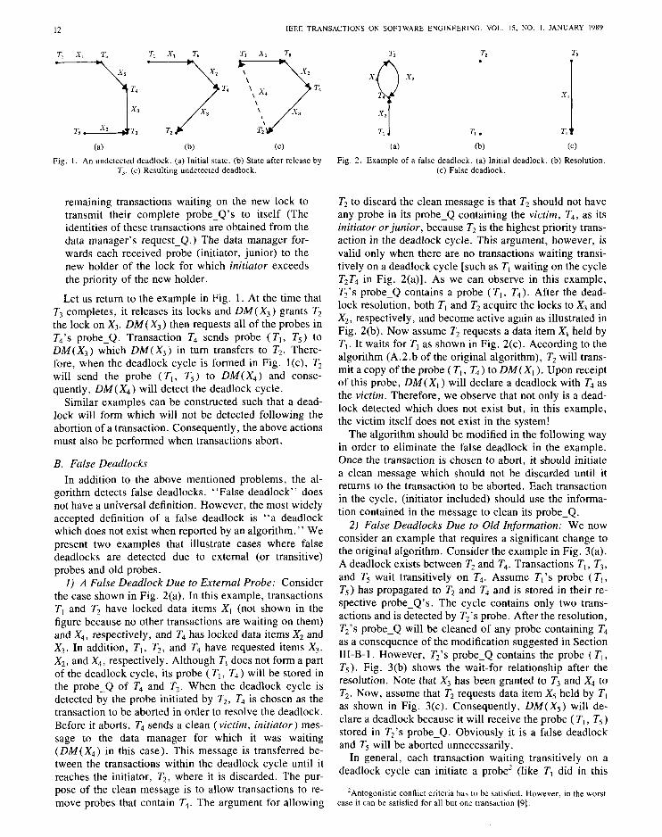
In this subsection we show why reinitiation and re- transmission of probes by those transactions which were earlier waiting transitively on a deadlock cycle, is re- quired. Fig. 4 shows a situation similar to one shown in Fig. 3. A deadlock cycle exists between transactions T3, T4, and TX. Transactions T, and T5 wait transitively on the deadlock cycle. Suppose T, initiated a probe (T,, T5) which is stored in the probe-Q’s of T,, T4 and T2. After the deadlock is detected at DM( X,) by the probe ( T2, T4), T4 is aborted as the deadlock victim. The modified reso- lution step cleans the probe-Q’s of T3 and T2 of all the probes including the probe (T,, T5). Fig. 4(b) shows the situation after the deadlock is resolved. Now, if T3 starts waiting for T,, a deadlock will be formed as shown in Fig. 4(c). Since T3’s probe-Q is empty and T3 is not the high- est priority transaction, this deadlock will not be detected unless either T=, retransmits its probe-Q or DM( X, ) rein- itiates a probe on behalf of T,.” Therefore, we observe that after a deadlock resolution, retransmission and rein- itiations of probes by those transactions which are waiting transitively on the deadlock cycle is needed.
‘If T, was directly waiting on the deadlock cycle then reinitiation would be necessary; in this example retransmission of probes by T5 is sufficient.
(a) (b) Cc) Fig. 4. An example illustrating the necessity of reinitiating and retrans-
mitting probes. (a) Initial deadlock. (b) After resolution. (c) Undetected deadlock.
D. Summary of Dejciencies We have presented examples illustrating those cases
where either the Probe Algorithm [9] fails to detect dead- locks, or detects false deadlock. Let us summarize the reasons for such deficiencies in the algorithm. First, the major cause for detecting false deadlock or failing to de- tect some deadlocks is that the algorithm overlooks the possibility that transactions may wait transitively on a deadlock cycle. Second, the algorithm fails to include those cases in which, after a transition releases locks, new transactions which now acquire those locks may get in- volved in a deadlock. This is because probes are either not initiated or transmitted more than once. Third, there are times when the algorithm detects false deadlocks be- cause transactions and data managers save old probes in probe-Q’s in order to reduce message overhead. This un- fortunately introduces the possibility of retaining old probes, which may later result in false deadlocks. All three of these problems were illustrated by the examples in Sec- tion III-B through Section 111-B-2. The next section con- tains the statement of the modified priority based probe algorithm in which these problems do not arise.
IV. MODIFIED PROBE ALGORITHM
In this section we present a modified probe algorithm which incorporates all the modifications we have sug- gested in the previous section. We keep the basic struc- ture of the original algorithm presented by Sinha and Na- tarajan [9] and incorporate the changes at the appropriate places. The changes are highlighted using boldface text. The algorithm makes no assumptions about the schedul- ing policy of a data manager. When two or more trans- actions simultaneously wait for a data item, the data man- ager may assign the lock for that data item to any transaction. In the case that the owner of a lock, holder releases the lock and it is assigned to some other trans- action, we shall refer to the second transaction as new holder.
A. The Revised Basic Deadlock Detection Algorithm The basic deadlock detection algorithm now has the fol-
lowing steps. 1) A data manager initiates, propagates, or reinitiates
a probe in the following situations. a) When a data item is locked by a transaction, if a
lock request arrives from another transaction, and re-

14 IEEE TRANSACTIONS ON SOFTWARE ENGINEERING, VOL. 15, NO. 1. JANUARY 1989
quester > holder, the data manager initiates a probe and sends it to the holder.
b) When the current holder releases a data item, the data manager schedules a “waiting lock request.” If there are more lock requests still in the request-Q, then for each lock request for which requester > new holder, the data manager initiates a probe and sends it to the new holder.
When a data manager initiates a probe it sets
initiator : = requester; junior : = holder;
c) When a transaction completes or aborts it re- leases its locks. The data manager associated with each released data item assigns the lock for the data item to some transaction (heretofore referred to as new holder) waiting for that data item (if one exists). Each data manager then requests all remaining transactions waiting on the new lock to transmit their complete probe-Q’s to itself. (The identities of these transac- tions is obtained from the data manager’s request Q.) The data manager forwards each received probe&i- tiutor, junior) to new holder the lock for which initiator > new holder.
2) Each transaction maintains a queue, called a probe-Q, where it stores all probes received by it. The probe-Q of a transaction contains information about the transactions which wait for it directly, or transitively. Since a transaction follows 2PL, the information con- tained in the probe-Q of a transaction remains valid until it aborts or commits.
After a transaction enters the second phase of the 2PL, it does not discard the probe-Q. However, dur- ing the second phase, any probe received is ignored.
Otherwise, a transaction sends a probe or a copy of its probe-Q to the data manager, where it is waiting in the following three cases.
a) When a transction T receives probe (initiator, junior), it performs the following.
if ( junior > T) then junior : = T, save the probe in the probe-Q; if T is in wait state then transmit a copy of the saved probe to the data
manager where it is waiting;
b) When a transaction issues a lock request to a data manager and waits for the lock to be granted (i.e., it goes from active to wait state), it transmits a copy of each probe stored in its probe-Q to that data manager.
c) If a transaction is waiting and receives a re- quest for its probe-Q from the data manager where it is waiting, it sends a copy of its probe-Q to the data manager. (This may occur as a consequence of part A.1.c.)
3) When a data manager receives probe (initiator, jun- ior) from one of its requesters, it performs the following.
if holder > initiator then discard the probe
else if holder < initiator then propagate the probe to the holder else declare deadlock and initiate deadlock resolu-
tion;
When a deadlock is detected, the detecting data manager has the identities of two members of the cycle, initiator and junior, i.e., the highest and lowest priority transac- tions, respectively. The junior is chosen as the deadlock victim.
B. The Deadlock Resolution and Post Resolution Computation
This consists of the following three steps. 1) To abort the victim, the data manager that detects
the deadlock sends an abort signal to the victim. The iden- tity of the initiator is also sent along with the abort signal: abort (victim, initiator). Since victim is aborted, it is nec- essary to discard those probes (from the probe-Q of var- ious transactions) that have victim as their junior or ini- tiator. Hence, on receiving an abort-signal, the victim does the following.
a) It initiates a message, clean (victim, initiator), sends it to the data manager where it is waiting.
b) The victim enters abort phase only when its clean message returns to itself. Once it enters the abort phase, the victim releases all the locks it held, with- draws its pending request, and aborts. During this phase, it discards any probe or clean message that it receives.
2) When a data manager receives clean (victim, initi- ator) message, it does the following.
a) It propagates the clean message to its holder. b) It reinitiates probes for each requester for
which requester > holder. c) It requests each transaction in the request-Q to
retransmit its probe-Q. This corresponds to part c) of A.l.
3) When a transaction T receives clean (junior, initi- ator) message, it acts as follows.
purge every probe from its probe-Q; if T is in wait state
then if T = junior then enter the abort phase and release all
locks else propagate the clean message to the data man-
ager where T is waiting else discard the clean message.
V. COMMENTS ON THE PERFORMANCE AND
CORRECTNESS OF THE ALGORITHM
The performance of the modified algorithm will be de- graded compared to the original algorithm by Sinha and Natarajan [9] because additional overhead is incurred in order for the algorithm to work correctly. We briefly dis- cuss the impact of the modifications on the message over- head and the delay involved for detecting deadlocks.
I) Message Overhead: The message overhead is the

CHOUDHARY PI al.: ALGORITHM FOR DISTRIBUTED DEADLOCK DETECTION AND RESOLUTION 15
number of messages that must be sent in order to perform deadlock detection. It is no longer true that if a deadlock was detected and resolved and, if later another deadlock forms involving all or a subset of the members of the first cycle, it will be detected using fewer messages as claimed in [9]. The reason is that after a deadlock is resolved, all members of the cycle discard all the probes from their probe_Q’s. Therefore, to detect the second deadlock in- volving the same transactions or a subset of these trans- actions, the number of messages are not reduced because probes need to be retransmitted. In fact, the number of messages to detect the second deadlock can be greater than the number required to detect the first deadlock. Trans- actions waiting transitively also have to send probes again, even though they were not a part of the cycle earlier and may not be a part of a cycle in the future.
2) Delay: The delay denotes the time required to de- tect a deadlock once the deadlock is formed. This also increases over that in the original algorithm because probes need to be retransmitted. Since the probe initiated on behalf of the highest priority transaction detects a deadlock, the delay depends on when the highest priority transaction enters the wait state. However, if the highest priority transaction has to retransmit or reinitiate a probe, the delay can be large even if the highest priority trans- action entered the wait state much earlier than the other members of the cycle. Fig. 4(c) is a good example of this situation. For the second deadlock in Fig. 4(c) it does not matter when T, entered the wait state. It has to retransmit its probe because the earlier probe was cleaned by all the transactions when the first deadlock was resolved.
In addition to the delay introduced due to reinitiation and retransmission, another form of delay is incurred in aborting a transaction. Part B 1 .a of the modified algo- rithm suggests that a deadlock victim releases its re- sources only after its clean message returns to itself. Therefore, transactions waiting on resources held by the victim can not acquire the resources even though the dead- lock has been detected and resolved. This is not exactly a delay for detecting a deadlock but a delay in the sub- sequent processing by transactions. This delay will al- ways be proportional to the deadlock cycle length.
We do not have a formal proof of correctness for the modified probe algorithm. Lacking a formal proof, the algorithm has been extensively tested through simulation. In fact, we discovered the deficiencies of the Sinha and Natarajan algorithm for exclusive locks while imple- menting that algorithm in a distributed database simula- tor. As we discovered the deficiencies described in Sec- tion III, we modified the algorithm until it became the algorithm found in Section IV. After this point in time, the algorithm neither failed to discover a deadlock nor detected a false deadlock. The algorithm has been tested by simulation for a distributed database system on five nodes each containing 1000 data items. The number of users on the system ranged from 2 to 200. Each user re- peatedly executed transactions until approximately 20 000 transactions were committed. Each transaction requested on the average 16 exclusive locks. The number of users
on the system was used to control the frequency of dead- lock occurrence. When the number of users was large ( -2OO), the probability that a transaction conflicts with another transaction on one data item request was 0.3. In this case, the probability of a transaction becoming part of a deadlock cycle on a single data item request lock was as high as 0.02. In these cases, the probability that a transaction would become part of a deadlock during its lifetime was approximately 0.3. These simulations pro- duced many deadlock cycles with an average length of ten. In addition many situations arose where transactions waited on deadlock cycle transitively. In each of these cases the modified algorithm performed correctly. The reader is referred to [5] for further details on the simula- tion study.
VI. CONCLUSIONS
In this paper we presented a modified probe algorithm based on priorities to detect and resolve deadlocks in dis- tributed database systems. We illustrated through various examples how the algorithm presented by Sinha and Na- tarajan [9] failed to work correctly in many situations. We observed that the major cause for detecting false deadlock or failing to detect some deadlocks is that the algorithm overlooks the possibility of transactions waiting transi- tively on a deadlock cycle. Also, the algorithm fails to include those cases in which, after a transaction releases locks, new transactions which now acquire those locks may get involved in a deadlock. We also suggested mod- ifications to the algorithm to eliminate the errors. Al- though we have not formally proven that the modified al- gorithm works in all possible cases, extensive simulation evidence leads us to believe that it is correct.
We would like to point out that the modifications we suggested for the basic algorithm are also required for the extended algorithm proposed by Sinha and Natarajan to detect deadlocks when shared and multiple lock requests are allowed. Since the Sinha and Natarajan extended al- gorithm includes the basic algorithm in its entirety, and those extensions do not resolve the deficiencies, all the modifications we suggested apply. A detailed discussion can be found in [5].
Finally, we would like to point out that it is important to implement and test a distributed algorithm in order to gain a high degree of confidence in whether it performs correctly if no formal proof of correctness is developed. This was apparently not done for the original Sinha and Natarajan algorithm.
APPENDIX THE PRIORITY BASED PROBE ALGORITHM
The following is a description of the basic deadlock de- tection algorithm reported by Sinha and Natarajan [9, pp. 69-701.
A. The Basic Deadlock Detection Algorithm The basic deadlock detection algorithm has three steps. 1) A data manager initiates a probe in the following
two situations.

16 IEEE TRANSACTIONS ON SOFTWARE ENGINEERING, VOL. 15, NO. I. JANUARY 1989
a) When a data item is locked by a transaction, if a lock request arrives from another transaction, and re- quester > holder, the data manager initiates a probe and sends it to the holder.
b) When a holder releases the data item, the data manager schedules a waiting lock request. If there are more lock requests still in the request-Q, then for each lock request for which requester > new holder, the data manager initiates a probe and sends it to the new holder.
When a data manager initiates a probe it sets
initiator : = requester; junior := holder;
2) Each transaction maintains a queue, called a probe-Q, where it stores all the probes received by it. The probe-Q of a transaction contains information about the transactions which wait for it directly, or transitively. Since a transaction follows 2PL, the information con- tained in the probe-Q of a transaction remains valid until the transaction aborts or commits.
After a transaction enters the second phase of the 2PL, it can never get involved in a deadlock. Hence, when it enters the second phase, it discards the probe-Q. During the second phase, any probe received is ignored.
A transaction sends a probe to the data manager, where it is waiting in the following two cases.
a) When a transaction T receives probe (initiator, junior), it performs the following.
if ( junior > T) then junior : = T, save the probe in the probe-Q; if T is in wait state then transmit a copy of the saved probe to the data
manager where it is waiting;
b) When a transaction issues a lock request to a data manager and waits for the lock to be granted (i.e., it goes from active to wait state), it transmits a copy of each probe stored in its probe-Q to that data manager.
3) When a data manager receives probe (initiator, jun- ior) from one of its requesters, it performs the following.
if holder > initiator then discard the probe else if holder < initiator
then propagate the probe to the holder else declare deadlock and initiate deadlock resolu-
tion;
When a deadlock is detected, the detecting data manager has the identities of the two members of the cycle, initi- ator and junior, i.e., the highest and lowest priority trans- actions, respectively. The junior is chosen as the dead- lock victim.
B. The Deadlock Resolution and Post Resolution Computation
This consists of the following three steps. 1) To abort the victim, the data manager that detects
the deadlock sends an abort signal to the victim. The iden-
tity of the initiator is also sent along with the abort signal: abort (victim, initiator). Since victim is aborted, it is nec- essary to discard those probes (from the probe-Q of var- ious transactions) that have victim as their junior or ini- tiator. Hence, on receiving an abort-signal, the victim does the following.
a) It initiates a message, clean (victim, initiator), sends it to the data manager where it is waiting, and enters the abort phase. Since the initiator is the highest priority transaction of the deadlock cycle, its probe-Q will never contain any probe generated by the other members of the cycle. Consequently, probe-Q’s of transactions, from in- itiator to victim in the direction of the probe traversal, will not contain a probe having victim as junior or initi- ator. And hence, the clean message carries the identity of the initiator beyond which it need not traverse.
b) In abort phase, the victim releases all the locks it held, withdraws its pending request, and aborts. During this phase, it discards any probe or clean message that it receives.
2) When a data manager receives clean (victim, initi- ator) message, it propagates the message to the holder of its data.
3) When a transaction T receives clean (victim, initi- ator) message, it acts as follows.
purge from the probe-Q every probe that has victim as its junior or initiator of that probe;
if T is in wait state then if T = initiator
then discard the clean message else propagate the clean message to the data man-
ager where it is waiting else discard the clean message;
A transaction discards the clean message in the follow- ing two situations: 1) the transaction is in active state or, 2) the transaction is the same as the initiator of the clean message received.
After “cleaning up” its probe-Q as described above, each member transaction of the deadlock cycle retains the remaining probes in its probe-Q. In the future, if the re- maining members (or any subset of them) get involved in a deadlock cycle, it will be detected with fewer number of messages, since probes have already traversed some edges of the cycle.
ACKNOWLEDGMENT
We would like to acknowledge M. Roesler for pointing out an error in the algorithm in an earlier version of this paper.
REFERENCES
[I] P. Bernstein and N. Goodman, “Concurrency control in distributed database systems,” ACM Compur. Surveys, vol. 13, no. 2, pp. 185 221, June 1981.
[2] -, “A sophisticates’s introduction to distributed database concur- rency control,” in Proc. 8th Int. Conf. Very Large Data Bases, Sept. 1982.
[3] K. M. Chandy and J. Misra, “A distributed algorithm for detecting resource deadlocks in distributed systems,” in Proc. ACM SIGACT-

CHOUDHARY of al.: ALGORITHM FOR DISTRIBUTED DEADLOCK DETECTION AND RESOLUTION 17
141
[51
161
I71
WI
191
SIGOPS Svmp. Principles of Distributed Computing. Ottawa, Ont., Canada, Aig: 1982. K. M. Chandv. J. Misra, and L. M. Haas, “Distributed deadlock de- tection,” ACM Trans. Comput. Syst., vol. 1. pp. 144-156. May 1983. A. N. Choudhary. “Two distributed deadlock detection algorithms and their performance, ” Master’s thesis, Dep. ECE, Univ. Massachusetts. Amherst. Feb. 1986. K. P. Eswaran. J. N. Gray, R. A. Lorie. and 1. L. Traiger. “The notion of consistency and predicate locks in a database system,” Com- mun. ACM, vol. 19, pp. 624-633. Nov. 1976. V. Gligor and S. H. Shattuck, “On deadlock detection in distributed systems, ” IEEE Truns. So&vat-e Eng.. vol. SE-6, no. 5, Sept. 1980. R. Obermarck. “Distributed deadlock detection algorithm,” ACM Trans. Database SW., vol. 7, pp. 187-208. June 1982. M. K. Sinha and N. Natarajan. *‘A priority based distributed deadlock detectIon algorithm,” IEEE Trans. Software Eng.. vol. SE-11. no. 1. pp. 67-80, Jan. 1985.
Alok N. Choudhary (S’88) received the B.E. (Hans.) degree in electrical engineering from Birla Insiitute of Technology and Science, Pilani, In- dia, in 1982. He worked as a Systems Analyst and Designer from 1982 to 1984. He received the M.S. degree in electrical and computer engineering from the University of Massachusetts. Amherst. in 1986.
He is currently with the Coordinated Science Laboratory. University of Illinois. Urbana-Cham- paign, where he is working toward the Ph.D. de-
gree. He was a Visiting Scientist at IBM. T. J. Watson Research Center. Yorktown Heights, NY. during the summers of 1987 and 1988. His re- search interests include computer architecture. parallel processing, parallel architectures for integrated vision systems. high speed transaction proces\- ing. and distributed computing.
Mr. Choudhary is a student member of the Association for Computing Machinery.
Walter H. Kohler (S’66-M’73-SM‘86) received the B.S.E.. M.S.. M.A., and Ph.D. degrees in electrical engineering from Princeton University. Princeton, NJ.
From 1968 to 1969 he was a member of the Technical Staff of Bell Telephone Laboratories, Holmdel. NJ. Since 1972 he has been with the Department of Electrical and Computer Engineer- ing, University of Massachusetts. Amherst. He has also been a consultant to research and devel- opment groups within the Digital Equipment Cor-
poration since 1979. His research interests include the design, measure- ment, and modeling of distributed computer systems.
Dr. Kohler is a member of the IEEE Computer Society and the Asso- ciation for Computing Machinery.
John A. Stankovic (S’77-M’79-SM’86) re- ceived the B.S. degree in electrical engineering and the M.S. and Ph.D. degrees in computer sci- ence from Brown University, Providence, RI. in 1970, 1976, and 1979, respectively.
He is currently an Associate Professor in the Department of Computer and Information Sci- ence, University of Massachusetts at Amherst. His current research interests include investigating various approaches to distributed scheduling on general-purpose but highly integrated distributed
systems, developing means for controlling and scheduling tasks on distrib- uted hard real-time systems, and developing database partitioning proto- cols.
Prof. Stankovic received an Outstanding Scholar Award from the School of Engineering, University of Massachusetts. He has recently published a tutorial text entitled Reliable Distributed System Softwwre (IEEE Computer Society), and was the General Chairman for the 1986 Real-Time Systems Symposium.
Don Towsley (M’78) received the B.A. degree in physics and the Ph.D. degree in computer sci- ences from the University of Texas at Austin in 1971 and 1975, respectively.
From 1976 to 1985 he was a member of the faculty of the Department of Electrical and Com- puter Engineering at the University of Massachu- setts, Amherst, where he achieved the rank of As- sociate Professor. He is currently an Associate Professor of Computer and Information Science at the University of Massachusetts. During 1982-
1983, he was a Visiting Scientist at the IBM Thomas J. Watson Research Center, Yorktown Heights. NY. His research interests are in computer net- works, distributed computer systems. and performance evaluation.
Dr. Towsley is currently an Associate Editor of Networks and IEEE TRANSACTIONS ON COMMUNICATIONS. He is also a member of the Associa- tion for Computing Machinery and the Operations Research Society of America.