Embed Size (px)
Citation preview

10. ACCEPTED EQUIPMENT
10.1 GENERAL In order to meet the minimum specifications of these Electric Service Requirements, certain equipment shall have the acceptance of the Company. Manufacturers of equipment covered by these regulations may be required to submit samples of such equipment for Company acceptance. The Company will list the manufacturer's catalog number of accepted equipment in the following tables of this section. Each table lists equipment that is accepted only for the class of service and conditions described in the table heading. Accepted equipment is not interchangeable between tables unless listed in each table by manufacturer's catalog number.
Prefix/suffix, number/letter variations to catalog numbers as listed, that identify items such as hub size of hub plate, are acceptable with local regional approval.
The company reserves the right to install security devices on equipment that contains unmetered conductors.
Accepted Equipment Rev-6 August, 2008 Page 1 of 23
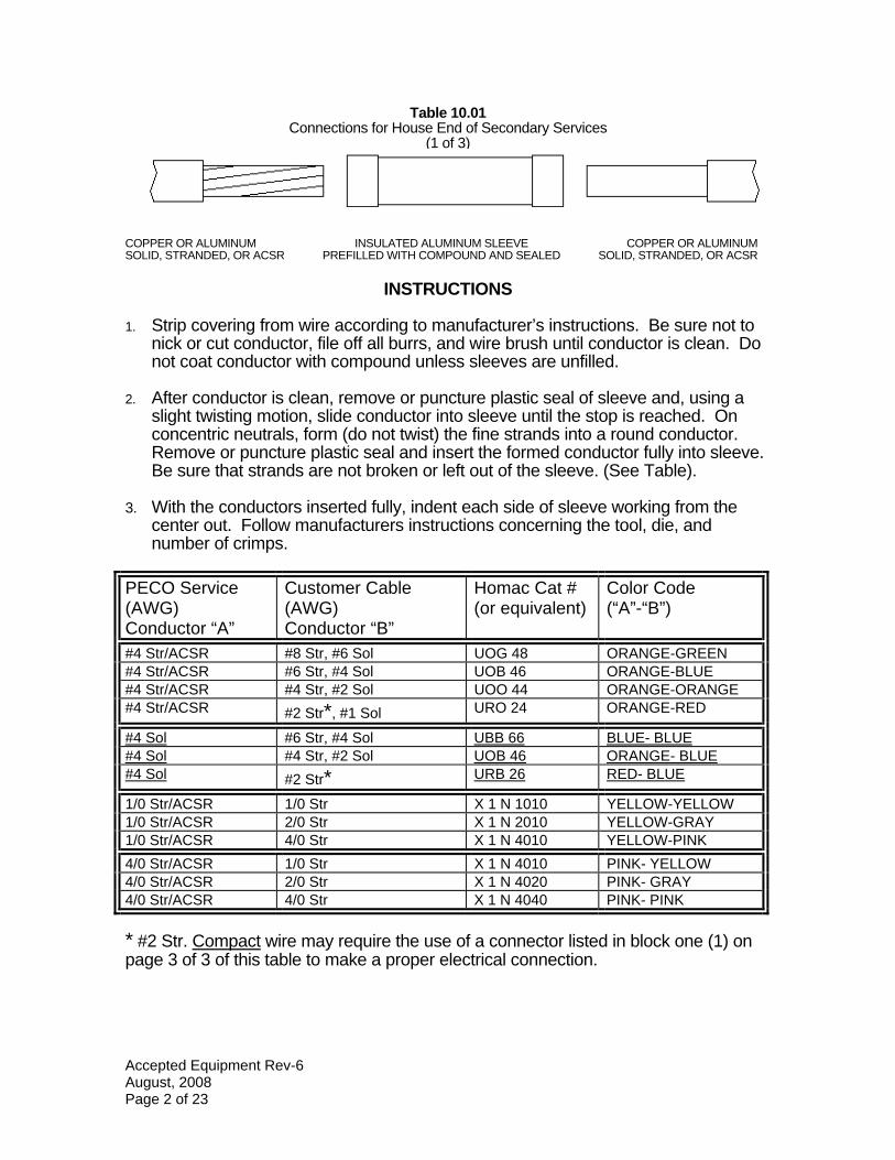
Table 10.01 Connections for House End of Secondary Services
(1 of 3)
COPPER OR ALUMINUM INSULATED ALUMINUM SLEEVE COPPER OR ALUMINUM SOLID, STRANDED, OR ACSR PREFILLED WITH COMPOUND AND SEALED SOLID, STRANDED, OR ACSR
INSTRUCTIONS
1. Strip covering from wire according to manufacturer’s instructions. Be sure not to nick or cut conductor, file off all burrs, and wire brush until conductor is clean. Do not coat conductor with compound unless sleeves are unfilled.
2. After conductor is clean, remove or puncture plastic seal of sleeve and, using a slight twisting motion, slide conductor into sleeve until the stop is reached. On concentric neutrals, form (do not twist) the fine strands into a round conductor. Remove or puncture plastic seal and insert the formed conductor fully into sleeve. Be sure that strands are not broken or left out of the sleeve. (See Table).
3. With the conductors inserted fully, indent each side of sleeve working from the center out. Follow manufacturers instructions concerning the tool, die, and number of crimps.
PECO Service (AWG) Conductor “A”
Customer Cable (AWG) Conductor “B”
Homac Cat # (or equivalent)
Color Code (“A”-“B”)
#4 Str/ACSR #8 Str, #6 Sol UOG 48 ORANGE-GREEN #4 Str/ACSR #6 Str, #4 Sol UOB 46 ORANGE-BLUE #4 Str/ACSR #4 Str, #2 Sol UOO 44 ORANGE-ORANGE #4 Str/ACSR #2 Str*, #1 Sol URO 24 ORANGE-RED
#4 Sol #6 Str, #4 Sol UBB 66 BLUE- BLUE #4 Sol #4 Str, #2 Sol UOB 46 ORANGE- BLUE #4 Sol #2 Str* URB 26 RED- BLUE
1/0 Str/ACSR 1/0 Str X 1 N 1010 YELLOW-YELLOW 1/0 Str/ACSR 2/0 Str X 1 N 2010 YELLOW-GRAY 1/0 Str/ACSR 4/0 Str X 1 N 4010 YELLOW-PINK 4/0 Str/ACSR 1/0 Str X 1 N 4010 PINK- YELLOW 4/0 Str/ACSR 2/0 Str X 1 N 4020 PINK- GRAY 4/0 Str/ACSR 4/0 Str X 1 N 4040 PINK- PINK
* #2 Str. Compact wire may require the use of a connector listed in block one (1) onpage 3 of 3 of this table to make a proper electrical connection.
Accepted Equipment Rev-6 August, 2008 Page 2 of 23

Table 10.01 Connectors for House End of Secondary Services
(2 of 3)
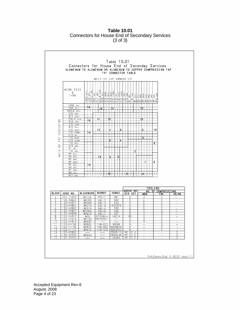
INSTRUCTIONS FOR INSTALLING COMPRESSION “ H “ TAP CONNECTORS
1. Use these connectors for non-tension splice or tap connections of aluminum-toaluminum conductors, or of aluminum to copper conductors, as shown above.
2. Be sure to use the correct size connectors and tooling as per manufacturersrecommendations.
3. Install the connectors so that the aluminum or ACSR conductors are physically above the copper conductors.
4. Strip conductor as shown above, wire brush until metal is clean. Apply antioxidant compound and make connection immediately.
CAUTION: Do not nick or cut conductors in stripping process!
5. Place stripped conductor in groove, allowing it to extend ½ “ beyond connectorfrom end to end using full number of indents as per manufacturersrecommendations.
6. Install an insulated tap cover if appropriate.
Accepted Equipment Rev-6 August, 2008 Page 3 of 23
DC D f(_)
::::, D z D (_)
0... <C f-
oe D
:z H <C ::e
BLOCK
1 2 3 4 5 6 7 8 8
1 0 11 1 2 1 3 14 1 5 1 6
Table 1 0.01 Connectors for House End of S econday Services
ALUMINUM TD ALUMINUM DR ALUMINUM TD COPPER COMPRESSION TAP "H" CONNECTOR TABLE
MAIN DR TAP CONDUCTOR
WI RE SIZE ID
& L • ~i • 0 o L C. L 0. ~ L L ro L ID
~ ~ 8~ ID E L....! L
TYPE ID~ ~ 0 0 0 ~ g ·a L L -' ID ~~ ~~~ ID ~ ID ID": ID ro ro o ~ (I) 0 0
D ID ID ID ro oD co D r--co Do OD OD OD OD D D D UJ UJ D r--c,,
U) --- ------ ------ ------ ------ ---- NM N...- ""'"' ...-co _ _ ,.._
U) U) ""'"' "'""' ""'"' ...-N -N -N ,,._
"""" """" """" """""" 1 ODO str. I I I I I I I I I I I I I I I I I I I -l--1 750 str. ,,-a1-,, ...1):" -,,,ti,77-~,,,--,,,ti,7-i-
55 6 .5 str. t-++--t- +--t-'j-f-t-t-- --t--1-t- +--t-1-t-t- --t-1 L-1- I I I I I II I I I I I I I I I I I
bUU str. L-1- _J 7 _L LLJ_ -LLJ_J-1-L.LJ__J_I_L.L+ _j_ 477 str. I I I.I I I I I I I I I I I I I I I I I I 33 6 .4 acsr 1.,.J ~~I~ T,r:zr-,,,77-,,,Tf13r,t 7-350 str. ..,
i ,,,--,,,7,-,--,,7-n-,, 7-
4/0 acsr t-+ --t-1-t- +-+-I- -+-+--+--t- -t-t-+--t-1-t-t-L -I-4/0 str. L-1- _j I_L _j__j_j _ _ .[_.[__j_j_ -LLJ__J_I-L.L+ _J_ 3 /0 acsr Ll_ _J~tL J__J'ZJ_ -tf-H-+H-H~~t, JJQ_ 4/U comp. 11-41 I I I I I I 2/0 str ,T ---j--1-(- I I I
-+-+--+---l- -(-+--+---l-la(-+--1-I
1 /0 acsr 11 ,---t----i- ----i-
2/0 comp t-+ --t-1-t- +-+.--1-=t~jj __ e---1--+--l-l-e-+-1--I-
-+_J_._ +-+~- -d-1 /0 str. L-1- _J-l-L J__j_J_ _.L.L-l_J __ L.LJ__J_I_L.L+ JL 2/0 sol. I I
~--j : I I I
: I : : : : : : : : It- + #1 str. I I I I I 1 /0 sol. rT ,--1-, T,,--, ,,,-rrc.r,-1-rr+ 7-
#2 str. ---t-1-r -t--t--1- -+- -t---t--1-rt-~---t-1-rt-L rt--.-+ --J_I_._ +-+-I- -\ -+-+--l-e---1- : -I-
#3 str. L-1- _j7L_a_ J__j5.J _ _ Jl! _j_j_J_L.L _J_I_L.L1 _J_ #2 sol. L-1- -b+ J__J_J_
-t -t+-H+ +1-~t, _J_ #4 acsr I I I I I Bl #4 str. ~11=
,--1-, T,,--, ,,,-rr ,-1-rr+ 7-#3 sol. 7--I-, ,---t----i- -, ---t7----i-,, 7-1-,,-1- 7-
#4 sol. t-+ --t-J-t- +-+-I- -+- -+--t--1-t-t- --t-1-t-+-t -I-
#8 sol. L-1-J__J-J-L tt7--tt+i~+ -t+:-a~t+ _j_l #1 0 sol. I I I I~ I I '
TDD LI NG BURNDY HDMAC
GttuvE DR NO. DF COMPRES SI DNS CODE NO. BLACKBURN DIE SET MDB Y35 45/46 132-14882 WR158 YH0-1 0B1 0 4 2 -132-14851 WR188 YH0-2 0B2 0 5 2 -132-14877 WR288 YHD-3 D83 D 5 2 -132-14884 WR278 YHD-4 D82020 D 5 2 -132-14852 WR378 YHD-5 D85 D 5 2 -132-14887 WR388L YHD-6 D86 D 7 3 -132-14888 WR418 YHD-7 D87 D 7 3 -132-14812 WR8 YPC2A8U-L UB214 BG 3 1 -132-14813 WRl 38 YPC26R8U-L - 0 4 2 -132-14914 WR502 - - D 4 2 -132-14136 WR885 YHN-525 NB500 N - 3 -132-14145 WR835 YHN-550 NB50040 N 2 -
132-14147 WR815 YHN-500 NB60020 N 2 -132-12855 - - ZB95410 KR OR z - 3 132-14232 WR949 - ZB95440 KR OR z - 3 132-14233 - - ZB854 KR OR z - - 5
Ref.Constr.Std. S-0252 sheet-11
Table 10.01 Connectors for House End of Secondary Services
(3 of 3)
Accepted Equipment Rev-6 August, 2008 Page 4 of 23

ACCEPTABLE EQUIPMENT
PRECAST MANHOLES
• 4’ x 6’ x 7’ deep inside dimensions (min.(*)) with traffic bearing 30” entry casting and manhole cover
• Local suppliers of precast manholes include A. C. Miller Concrete Products and Rotundo Pre-cast
PRECAST 3 PHASE TRANSFORMER FOUNDATION
• 7’ X 7’ OR 8’ X 8’ Top • Local suppliers of precast transformer foundations include A. C. Miller Concrete
Products and Rotundo Pre-cast
WALL MOUNTED METAL SPLICE BOX
• 42” X 42” X 24” deep (min.(*)), NEMA 3R rated; with a 36” piece of perforated Unistrut welded horizontally to the inside back of the cabinet 18” from the top and centered left to right; with 2 hinged, gasketed, lockable doors (3 - point latch mechanism with padlocking handle) - Unity Manufacturing # PEC424224DDCT3 or equivalent.
• 60” X 42” X 24” deep, NEMA 3R rated; with a 54” piece of perforated Unistrut welded horizontally to the inside back of the cabinet 18” from the top and centered left to right; with 2 hinged, gasketed, lockable doors (3 - point latch mechanism with padlocking handle) - Unity Manufacturing # PEC604224DDCT3 or equivalent.
PEDESTAL TYPE SPLICE MODULE (*)
• Durham model # AMSPR32127-0 with fiberglass ground sleeve / without primary hardware
• Nordic model # ND-350 without primary hardware • Power Design, Inc. model # CJP-30-41-L2-MG-1462-NPJ without primary hardware
FIBERGLASS SWITCH MODULE BASES
• 43” X 37 ½” (4KV & 15KV Distribution) • 65” x 69 ½” (34KV Distribution) • Highline Fiberglass Products, Nordic Fiberglass Products, Electraglass
(*) = Sizes listed are minimums. Larger sizes may be necessary dependent upon the load requirements of your project.
Accepted Equipment Rev-6 August, 2008 Page 5 of 23
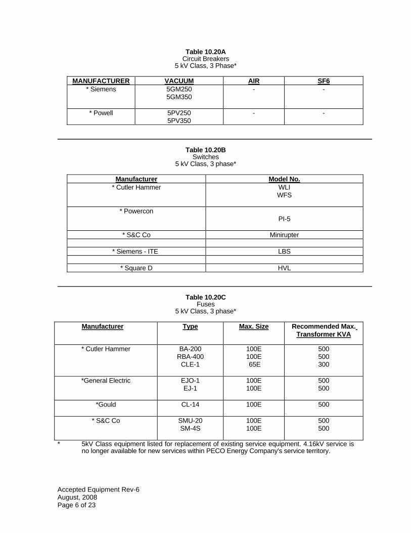
Table 10.20A Circuit Breakers
5 kV Class, 3 Phase*
MANUFACTURER VACUUM AIR SF6 * Siemens 5GM250
5GM350 - -
* Powell 5PV250 5PV350
- -
Table 10.20B Switches
5 kV Class, 3 phase*
Manufacturer Model No. * Cutler Hammer WLI
WFS
* Powercon PI-5
* S&C Co Minirupter
* Siemens - ITE LBS
* Square D HVL
Table 10.20C Fuses
5 kV Class, 3 phase*
Manufacturer Type Max. Size Recommended Max. Transformer KVA
* Cutler Hammer BA-200 RBA-400
CLE-1
100E 100E 65E
500 500 300
*General Electric EJO-1 EJ-1
100E 100E
500 500
*Gould CL-14 100E 500
* S&C Co SMU-20 SM-4S
100E 100E
500 500
* 5kV Class equipment listed for replacement of existing service equipment. 4.16kV service is no longer available for new services within PECO Energy Company's service territory.
Accepted Equipment Rev-6 August, 2008 Page 6 of 23
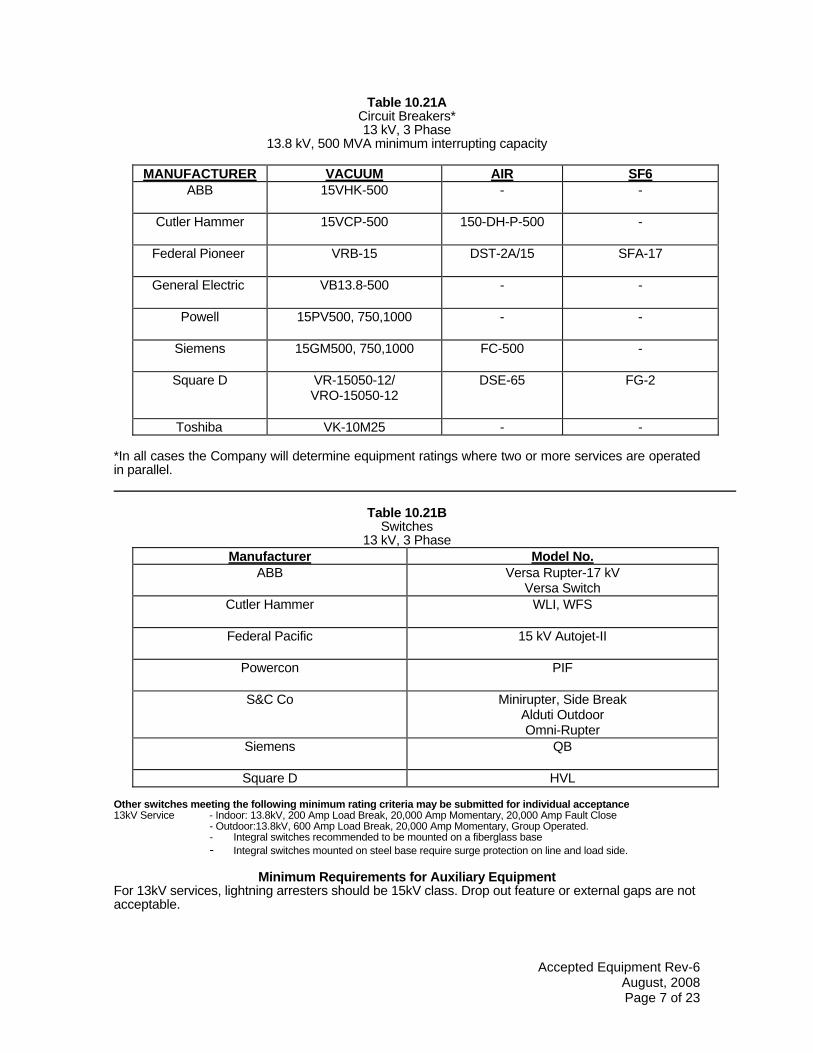
Table 10.21A Circuit Breakers* 13 kV, 3 Phase
13.8 kV, 500 MVA minimum interrupting capacity
MANUFACTURER VACUUM AIR SF6 ABB 15VHK-500 - -
Cutler Hammer 15VCP-500 150-DH-P-500 -
Federal Pioneer VRB-15 DST-2A/15 SFA-17
General Electric VB13.8-500 - -
Powell 15PV500, 750,1000 - -
Siemens 15GM500, 750,1000 FC-500 -
Square D VR-15050-12/ VRO-15050-12
DSE-65 FG-2
Toshiba VK-10M25 - -
*In all cases the Company will determine equipment ratings where two or more services are operated in parallel.
Table 10.21B Switches
13 kV, 3 Phase Manufacturer Model No.
ABB Versa Rupter-17 kV Versa Switch
Cutler Hammer WLI, WFS
Federal Pacific 15 kV Autojet-II
Powercon PIF
S&C Co Minirupter, Side Break Alduti Outdoor Omni-Rupter
Siemens QB
Square D HVL
Other switches meeting the following minimum rating criteria may be submitted for individual acceptance13kV Service - Indoor: 13.8kV, 200 Amp Load Break, 20,000 Amp Momentary, 20,000 Amp Fault Close
- Outdoor:13.8kV, 600 Amp Load Break, 20,000 Amp Momentary, Group Operated. - Integral switches recommended to be mounted on a fiberglass base - Integral switches mounted on steel base require surge protection on line and load side.
Minimum Requirements for Auxiliary Equipment For 13kV services, lightning arresters should be 15kV class. Drop out feature or external gaps are not acceptable.
Accepted Equipment Rev-6 August, 2008 Page 7 of 23
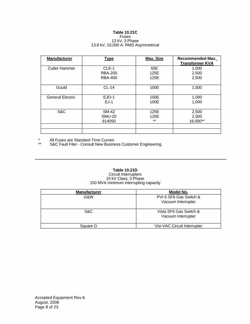
Table 10.21C Fuses
13 kV, 3 Phase 13.8 kV, 10,000 A. RMS Asymmetrical
Manufacturer Type Max. Size Recommended Max. Transformer KVA
Cutler Hammer CLE-1 RBA-200 RBA-400
65E 125E 125E
1,000 2,500 2,500
Gould CL-14 100E 1,500
General Electric EJO-1 EJ-1
100E 100E
1,000 1,000
S&C SM-4Z SMU-20 814050
125E 125E
**
2,500 2,500
16,000**
* All Fuses are Standard Time Curves ** S&C Fault Fiter - Consult New Business Customer Engineering
Table 10.21D Circuit Interrupters
15 kV Class, 3 Phase 150 MVA minimum interrupting capacity
Manufacturer Model No. G&W PVI-5 SF6 Gas Switch &
Vacuum Interrupter
S&C Vista SF6 Gas Switch & Vacuum Interrupter
Square D Visi-VAC Circuit Interrupter
Accepted Equipment Rev-6 August, 2008 Page 8 of 23
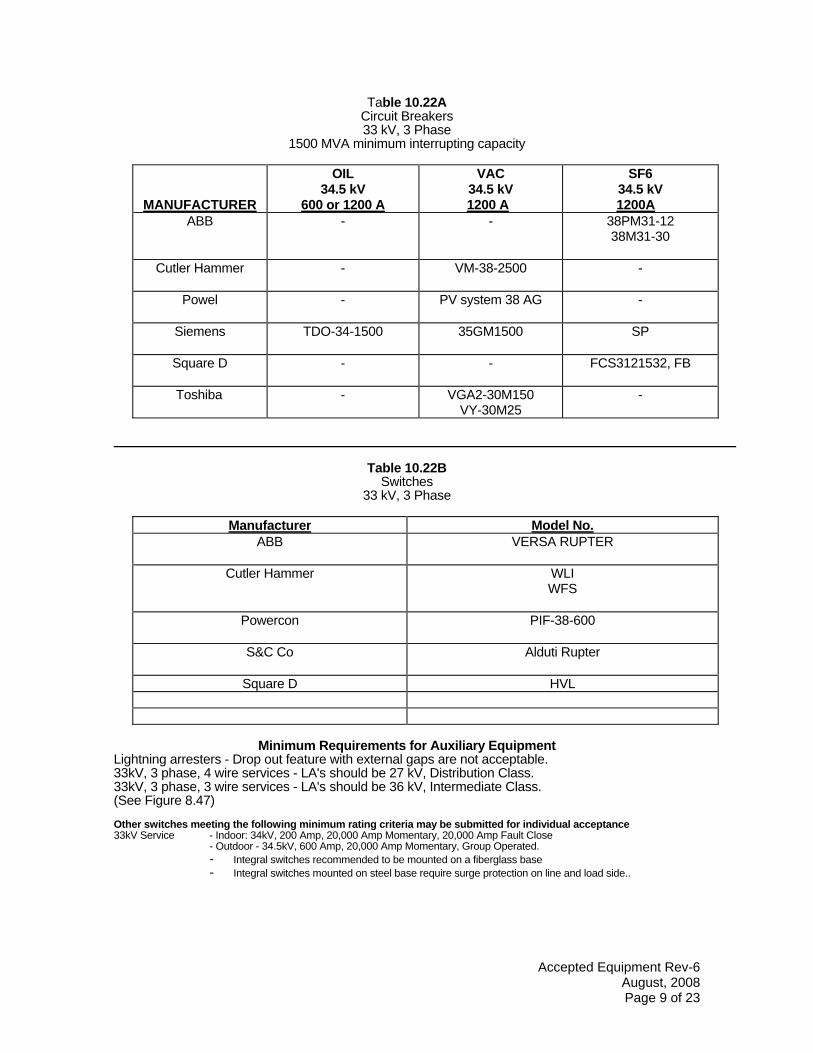
Table 10.22A Circuit Breakers 33 kV, 3 Phase
1500 MVA minimum interrupting capacity
MANUFACTURER
OIL 34.5 kV
600 or 1200 A
VAC 34.5 kV 1200 A
SF6 34.5 kV 1200A
ABB - - 38PM31-12 38M31-30
Cutler Hammer - VM-38-2500 -
Powel - PV system 38 AG -
Siemens TDO-34-1500 35GM1500 SP
Square D - - FCS3121532, FB
Toshiba - VGA2-30M150 VY-30M25
-
Table 10.22B Switches
33 kV, 3 Phase
Manufacturer Model No. ABB VERSA RUPTER
Cutler Hammer WLI WFS
Powercon PIF-38-600
S&C Co Alduti Rupter
Square D HVL
Minimum Requirements for Auxiliary Equipment Lightning arresters - Drop out feature with external gaps are not acceptable. 33kV, 3 phase, 4 wire services - LA's should be 27 kV, Distribution Class. 33kV, 3 phase, 3 wire services - LA's should be 36 kV, Intermediate Class. (See Figure 8.47)
Other switches meeting the following minimum rating criteria may be submitted for individual acceptance33kV Service - Indoor: 34kV, 200 Amp, 20,000 Amp Momentary, 20,000 Amp Fault Close
- Outdoor - 34.5kV, 600 Amp, 20,000 Amp Momentary, Group Operated. - Integral switches recommended to be mounted on a fiberglass base - Integral switches mounted on steel base require surge protection on line and load side..
Accepted Equipment Rev-6 August, 2008 Page 9 of 23
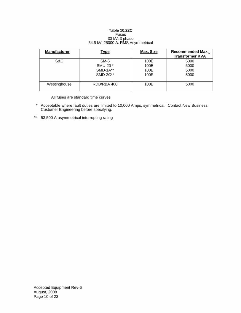
Table 10.22C Fuses
33 kV, 3 phase34.5 kV, 28000 A. RMS Asymmetrical
Manufacturer Type Max. Size Recommended Max. Transformer KVA
S&C SM-5 SMU-20 * SMD-1A** SMD-2C**
100E 100E 100E 100E
5000 5000 5000 5000
Westinghouse RDB/RBA 400 100E 5000
All fuses are standard time curves
* Acceptable where fault duties are limited to 10,000 Amps, symmetrical. Contact New Business Customer Engineering before specifying.
** 53,500 A asymmetrical interrupting rating
Accepted Equipment Rev-6 August, 2008 Page 10 of 23
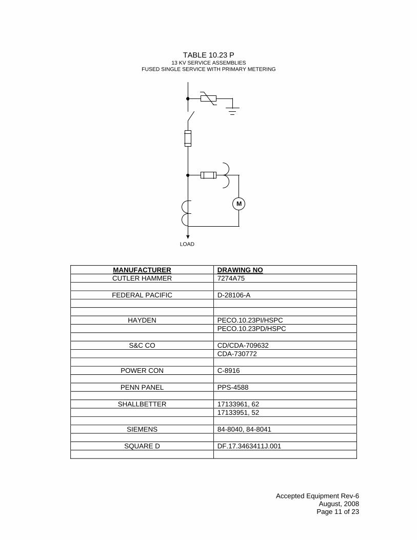
TABLE 10.23 P 13 KV SERVICE ASSEMBLIES
FUSED SINGLE SERVICE WITH PRIMARY METERING
M
LOAD
MANUFACTURER DRAWING NO CUTLER HAMMER 7274A75
FEDERAL PACIFIC D-28106-A
HAYDEN PECO.10.23PI/HSPC PECO.10.23PD/HSPC
S&C CO CD/CDA-709632 CDA-730772
POWER CON C-8916
PENN PANEL PPS-4588
SHALLBETTER 17133961, 62 17133951, 52
SIEMENS 84-8040, 84-8041
SQUARE D DF.17.3463411J.001
Accepted Equipment Rev-6 August, 2008
Page 11 of 23
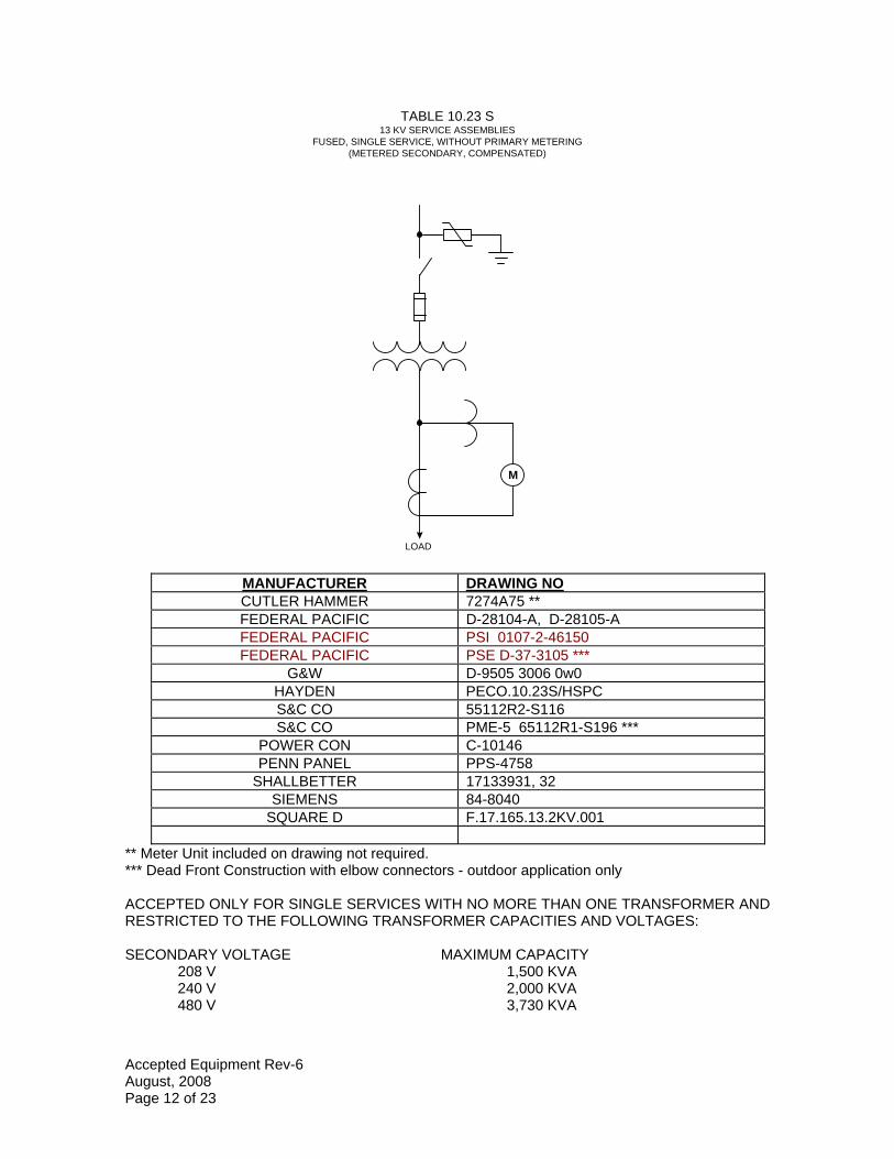
TABLE 10.23 S 13 KV SERVICE ASSEMBLIES
FUSED, SINGLE SERVICE, WITHOUT PRIMARY METERING (METERED SECONDARY, COMPENSATED)
M
LOAD
MANUFACTURER DRAWING NO CUTLER HAMMER 7274A75 ** FEDERAL PACIFIC D-28104-A, D-28105-A FEDERAL PACIFIC PSI 0107-2-46150 FEDERAL PACIFIC PSE D-37-3105 ***
G&W D-9505 3006 0w0 HAYDEN PECO.10.23S/HSPC S&C CO 55112R2-S116 S&C CO PME-5 65112R1-S196 ***
POWER CON C-10146 PENN PANEL PPS-4758
SHALLBETTER 17133931, 32 SIEMENS 84-8040
SQUARE D F.17.165.13.2KV.001
** Meter Unit included on drawing not required. *** Dead Front Construction with elbow connectors - outdoor application only
ACCEPTED ONLY FOR SINGLE SERVICES WITH NO MORE THAN ONE TRANSFORMER AND RESTRICTED TO THE FOLLOWING TRANSFORMER CAPACITIES AND VOLTAGES:
SECONDARY VOLTAGE MAXIMUM CAPACITY 208 V 1,500 KVA 240 V 2,000 KVA 480 V 3,730 KVA
Accepted Equipment Rev-6 August, 2008 Page 12 of 23
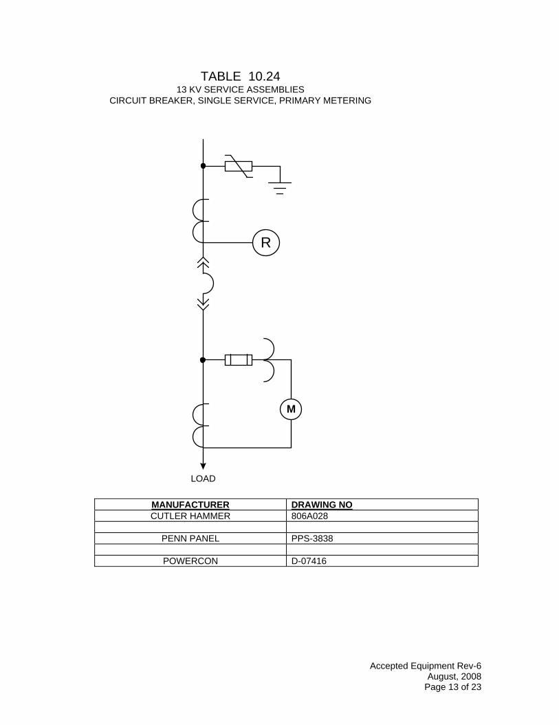
TABLE 10.24 13 KV SERVICE ASSEMBLIES
CIRCUIT BREAKER, SINGLE SERVICE, PRIMARY METERING
M
R
LOAD
MANUFACTURER DRAWING NO CUTLER HAMMER 806A028
PENN PANEL PPS-3838
POWERCON D-07416
Accepted Equipment Rev-6 August, 2008
Page 13 of 23
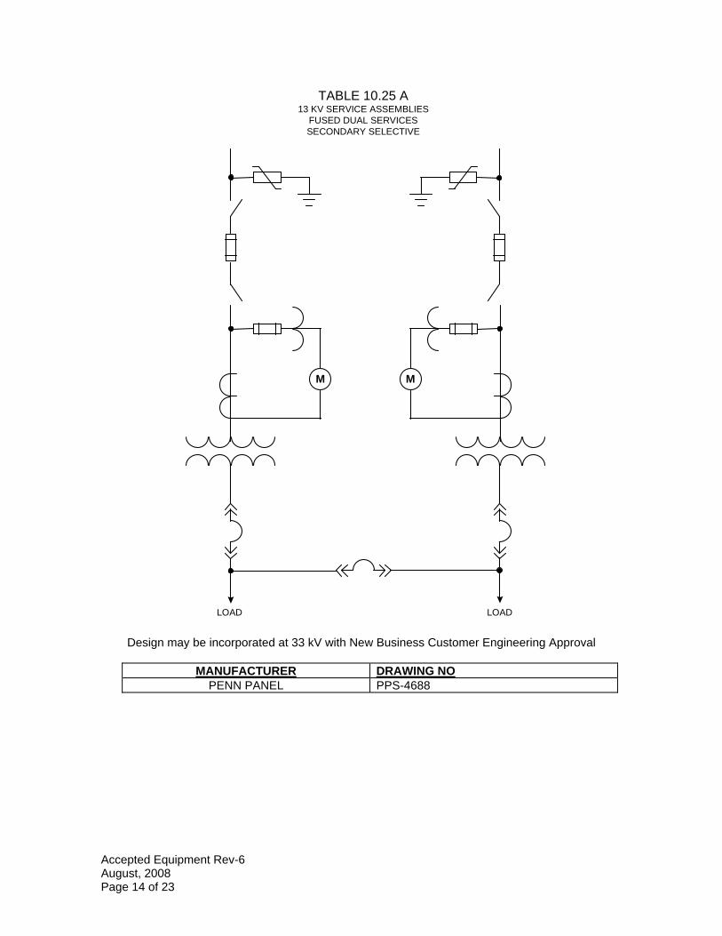
TABLE 10.25 A 13 KV SERVICE ASSEMBLIES
FUSED DUAL SERVICES SECONDARY SELECTIVE
M M
LOAD LOAD
Design may be incorporated at 33 kV with New Business Customer Engineering Approval
MANUFACTURER DRAWING NO PENN PANEL PPS-4688
Accepted Equipment Rev-6 August, 2008 Page 14 of 23
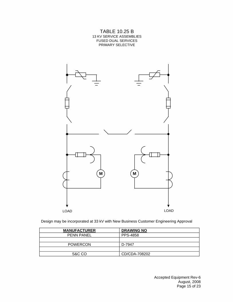
TABLE 10.25 B 13 KV SERVICE ASSEMBLIES
FUSED DUAL SERVICES PRIMARY SELECTIVE
M M
LOAD LOAD
Design may be incorporated at 33 kV with New Business Customer Engineering Approval
MANUFACTURER DRAWING NO PENN PANEL PPS-4858
POWERCON D-7947
S&C CO CD/CDA-708202
Accepted Equipment Rev-6 August, 2008
Page 15 of 23
-
~>-0 O<~
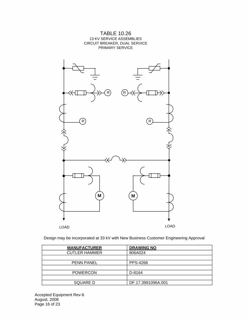
TABLE 10.26 13 KV SERVICE ASSEMBLIES
CIRCUIT BREAKER, DUAL SERVICE PRIMARY SERVICE
M M
R R
R R
LOAD LOAD
Design may be incorporated at 33 kV with New Business Customer Engineering Approval
MANUFACTURER DRAWING NO CUTLER HAMMER 806A024
PENN PANEL PPS-4268
POWERCON D-8164
SQUARE D DF.17.3991096A.001
Accepted Equipment Rev-6 August, 2008 Page 16 of 23
~ - -
\
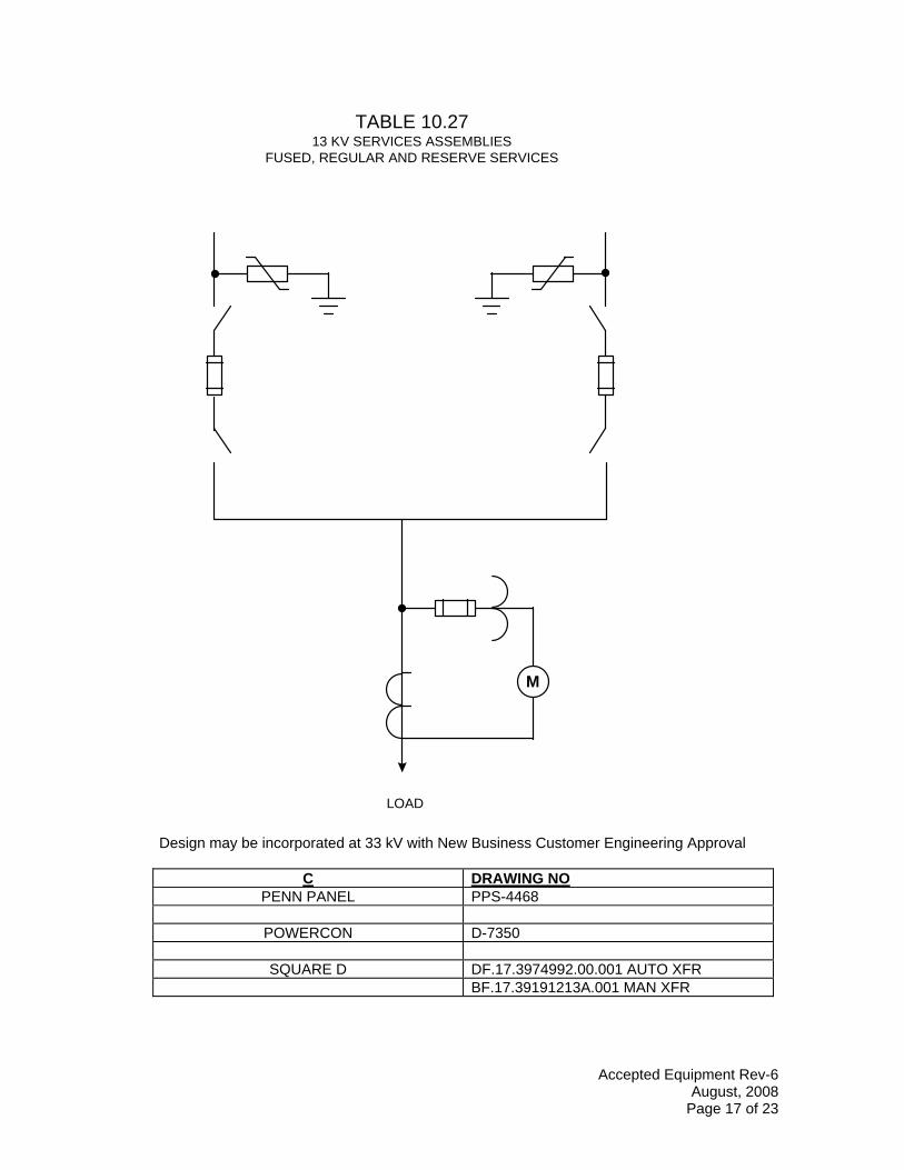
TABLE 10.27 13 KV SERVICES ASSEMBLIES
FUSED, REGULAR AND RESERVE SERVICES
M
LOAD
Design may be incorporated at 33 kV with New Business Customer Engineering Approval
C DRAWING NO PENN PANEL PPS-4468
POWERCON D-7350
SQUARE D DF.17.3974992.00.001 AUTO XFR BF.17.39191213A.001 MAN XFR
Accepted Equipment Rev-6 August, 2008
Page 17 of 23
- -- -
~>-{) 0<frr=m
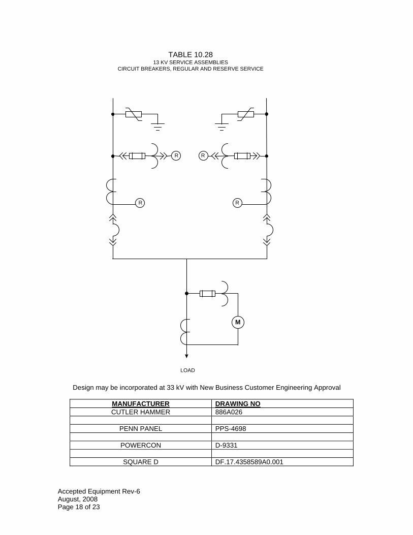
TABLE 10.28 13 KV SERVICE ASSEMBLIES
CIRCUIT BREAKERS, REGULAR AND RESERVE SERVICE
R
M
R
R R
LOAD
Design may be incorporated at 33 kV with New Business Customer Engineering Approval
MANUFACTURER DRAWING NO CUTLER HAMMER 886A026
PENN PANEL PPS-4698
POWERCON D-9331
SQUARE D DF.17.4358589A0.001
Accepted Equipment Rev-6 August, 2008 Page 18 of 23
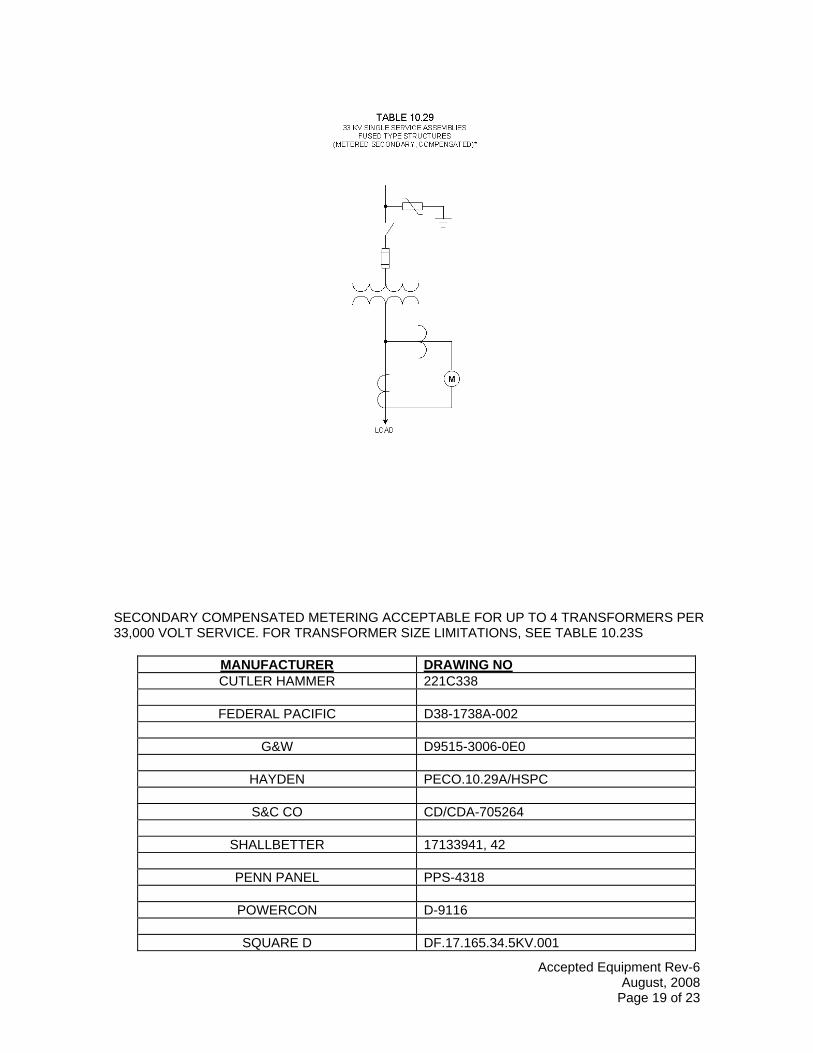
TABLE 10.29 33 KV SINGLE SERVICE ASSEMBLIES
FUSED TYPE STRUCTURES (METERED SECOND/IRY. COMPENSATED)'
LOAD
SECONDARY COMPENSATED METERING ACCEPTABLE FOR UP TO 4 TRANSFORMERS PER 33,000 VOLT SERVICE. FOR TRANSFORMER SIZE LIMITATIONS, SEE TABLE 10.23S
MANUFACTURER DRAWING NO CUTLER HAMMER 221C338
FEDERAL PACIFIC D38-1738A-002
G&W D9515-3006-0E0
HAYDEN PECO.10.29A/HSPC
S&C CO CD/CDA-705264
SHALLBETTER 17133941, 42
PENN PANEL PPS-4318
POWERCON D-9116
SQUARE D DF.17.165.34.5KV.001
Accepted Equipment Rev-6 August, 2008
Page 19 of 23
M
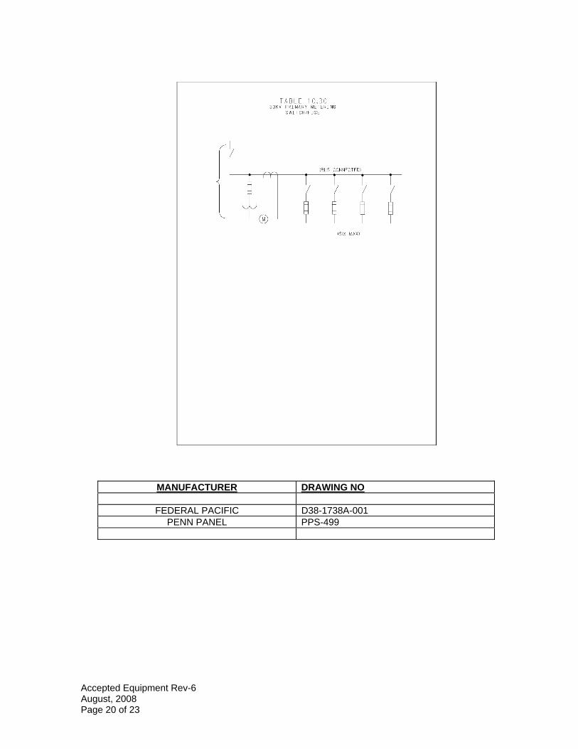
TABLE 10.30 33KV PRIMARY METER I NG
SWITCH/FUSE
(BUS CONNECTED)
ISIX MAX)
MANUFACTURER DRAWING NO
FEDERAL PACIFIC D38-1738A-001 PENN PANEL PPS-499
Accepted Equipment Rev-6 August, 2008 Page 20 of 23
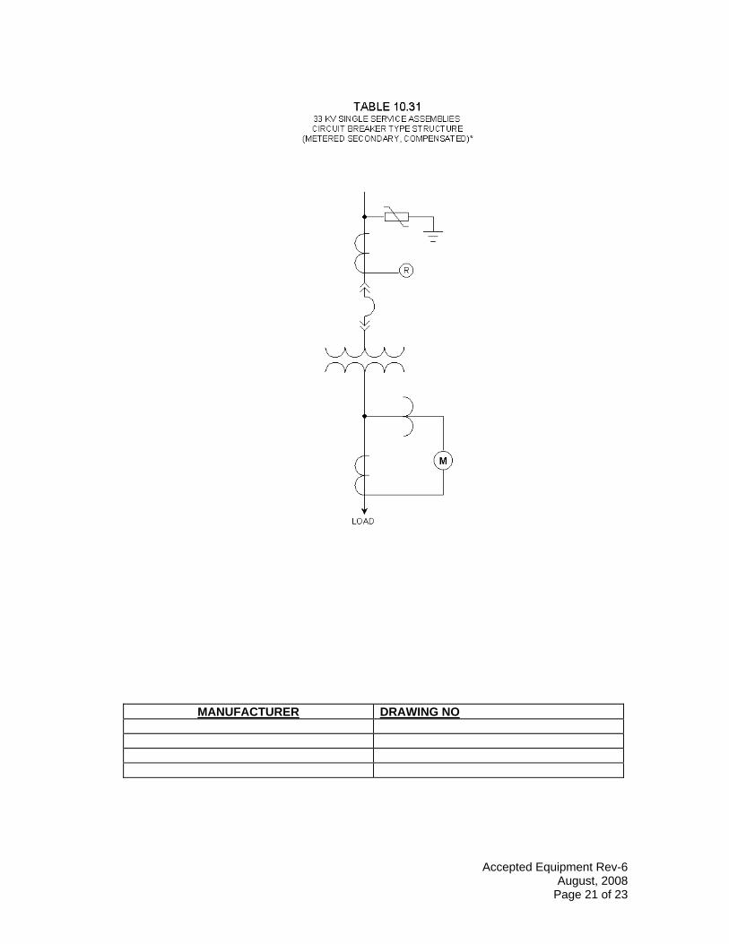
TABLE 10.31 33 KV SINGLE SERVICE ASSEMBLIES CIRCUIT BREAKER TYPE STRUCTURE
(METERED SEC ON DAR Y, COMPENSATED)*
M
LOAD
MANUFACTURER DRAWING NO
Accepted Equipment Rev-6 August, 2008
Page 21 of 23
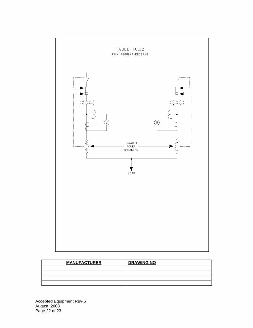
TABLE 10.32 33KV REGULAR/RESERVE
i-----i--I L ____ •
r----• ii_! •----J •----,
M
I): DRAW OUT :J' -------- ) ...... a------- POWER ----------1~• ( --------
'V BREAKERS \V
y i y LOAD
MANUFACTURER DRAWING NO
Accepted Equipment Rev-6 August, 2008 Page 22 of 23
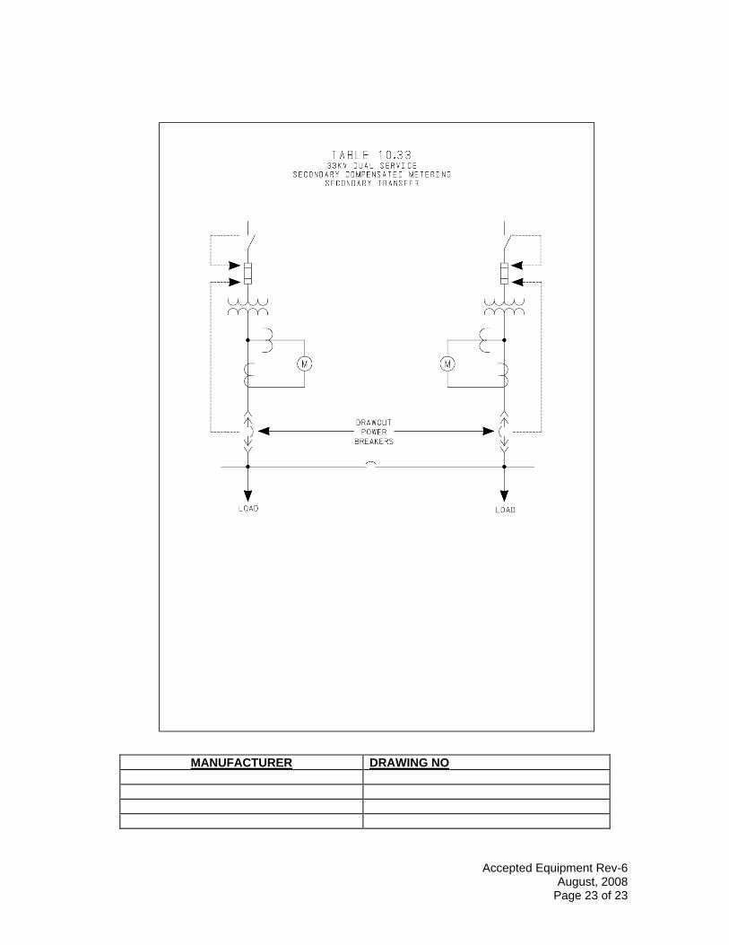
TABLE 10.33 33KV DUAL SERVICE
SECONDARY COMPENSATED METERING SECONDARY TRANSFER
M M
ii ..... .
•----J •----,
~ DRAWOUT '.I' -------- ) ....... ________ POWER ________ ..,_ ( --------
---------------! -BR:_KERS --------+----I
LOAD LOAD
MANUFACTURER DRAWING NO
Accepted Equipment Rev-6 August, 2008
Page 23 of 23