Embed Size (px)
Citation preview

10 & 20 TON UTILITY PRESS
OWNERS MANUAL
BENCH AND FLOOR MODEL PRESSES
10 & 20 Ton single acting manual hydraulic press
FOR YOUR OWN SAFETY AND
OPTIMUM OPERATION READ
INSTRUCTION MANUAL BEFORE
OPERATING PRESS
RETAIN THIS MANUAL FOR
FURTHER REFERENCE.
10 TON BENCH PRESS 10 TON FLOOR PRESS 20 TON FLOOR PRESS
# 972200 #972210 #972220
1
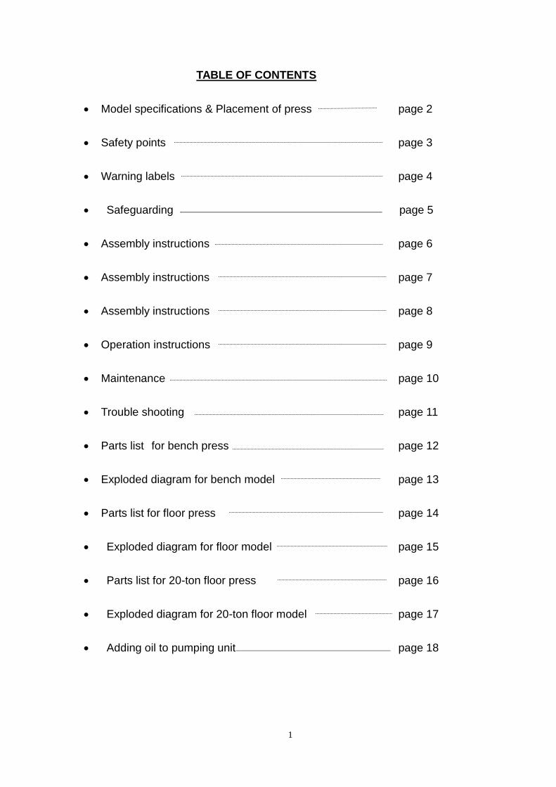
TABLE OF CONTENTS
• Model specifications & Placement of press page 2
• Safety points page 3
• Warning labels page 4
• Safeguarding page 5
• Assembly instructions page 6
• Assembly instructions page 7
• Assembly instructions page 8
• Operation instructions page 9
• Maintenance page 10
• Trouble shooting page 11
• Parts list for bench press page 12
• Exploded diagram for bench model page 13
• Parts list for floor press page 14
• Exploded diagram for floor model page 15
• Parts list for 20-ton floor press page 16
• Exploded diagram for 20-ton floor model page 17
• Adding oil to pumping unit page 18
2
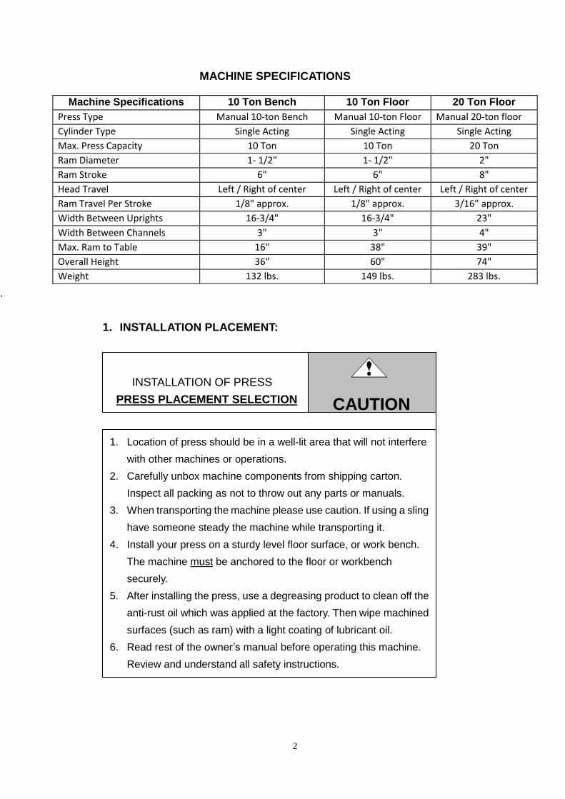
MACHINE SPECIFICATIONS
.
1. INSTALLATION PLACEMENT:
CAUTION
Machine Specifications 10 Ton Bench 10 Ton Floor 20 Ton Floor
Press Type Manual 10-ton Bench Manual 10-ton Floor Manual 20-ton floor
Cylinder Type Single Acting Single Acting Single Acting
Max. Press Capacity 10 Ton 10 Ton 20 Ton
Ram Diameter 1- 1/2" 1- 1/2" 2"
Ram Stroke 6" 6" 8"
Head Travel Left / Right of center Left / Right of center Left / Right of center
Ram Travel Per Stroke 1/8" approx. 1/8" approx. 3/16” approx.
Width Between Uprights 16-3/4" 16-3/4" 23"
Width Between Channels 3" 3" 4"
Max. Ram to Table 16" 38" 39"
Overall Height 36" 60" 74"
Weight 132 lbs. 149 lbs. 283 lbs.
INSTALLATION OF PRESS
PRESS PLACEMENT SELECTION
1. Location of press should be in a well-lit area that will not interfere
with other machines or operations.
2. Carefully unbox machine components from shipping carton.
Inspect all packing as not to throw out any parts or manuals.
3. When transporting the machine please use caution. If using a sling
have someone steady the machine while transporting it.
4. Install your press on a sturdy level floor surface, or work bench.
The machine must be anchored to the floor or workbench
securely.
5. After installing the press, use a degreasing product to clean off the
anti-rust oil which was applied at the factory. Then wipe machined
surfaces (such as ram) with a light coating of lubricant oil.
6. Read rest of the owner’s manual before operating this machine.
Review and understand all safety instructions.
3
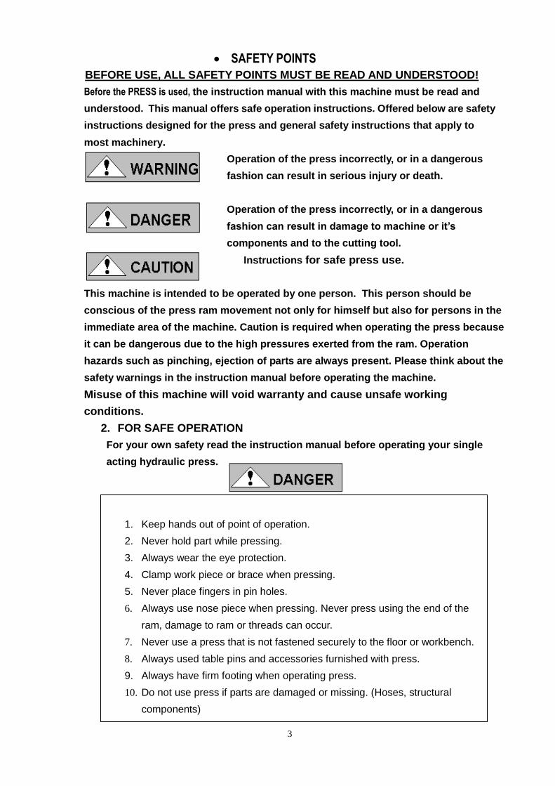
1. Keep hands out of point of operation.
2. Never hold part while pressing.
3. Always wear the eye protection.
4. Clamp work piece or brace when pressing.
5. Never place fingers in pin holes.
6. Always use nose piece when pressing. Never press using the end of the
ram, damage to ram or threads can occur.
7. Never use a press that is not fastened securely to the floor or workbench.
8. Always used table pins and accessories furnished with press.
9. Always have firm footing when operating press.
10. Do not use press if parts are damaged or missing. (Hoses, structural
components)
• SAFETY POINTS
BEFORE USE, ALL SAFETY POINTS MUST BE READ AND UNDERSTOOD!
Before the PRESS is used, the instruction manual with this machine must be read and
understood. This manual offers safe operation instructions. Offered below are safety
instructions designed for the press and general safety instructions that apply to
most machinery.
Operation of the press incorrectly, or in a dangerous
fashion can result in serious injury or death.
Operation of the press incorrectly, or in a dangerous
fashion can result in damage to machine or it’s
components and to the cutting tool.
Instructions for safe press use.
Intend use :
This machine is intended to be operated by one person. This person should be
conscious of the press ram movement not only for himself but also for persons in the
immediate area of the machine. Caution is required when operating the press because
it can be dangerous due to the high pressures exerted from the ram. Operation
hazards such as pinching, ejection of parts are always present. Please think about the
safety warnings in the instruction manual before operating the machine.
Misuse of this machine will void warranty and cause unsafe working
conditions.
2. FOR SAFE OPERATION
For your own safety read the instruction manual before operating your single
acting hydraulic press.

4
3. WARNING LABELS:
READ AND UNDERSTAND THESE WARNING LABELS PLACED ON THIS
MACHINE BEFORE OPERATING. MAKE SURE ALL PERSONS IN THE AREA
OF THE PRESS ARE AWARE OF THESE WARNINGS.
UNDER NO CIRCUMSTANCES SHOULD THESE LABELS BE REMOVED!
Establish solid footing Keep hands away Guard workpiece to
To prevent falls from point of prevent projectiles
operation from reaching operator
WEAR EYE PROTECTION
All pins must be inserted before
applying any pressure Keep finger out of pin holes
5
SAFEGUARDING THE POINT OF OPERATION
ANSI B11.2 – Hydraulic Power Presses
Safety Requirements for Construction, Care and Use
It is important that Dake press users have a clear understanding of their responsibility
involving the care and use of their Dake hydraulic press, including point-of-operation safe
guards. Dake strongly recommends that Dake press users obtain a copy of the current
American National Standard Institute (ANSI) B11.2 standard, for a more complete
understanding of their responsibilities.
ANSI B11.2 states the following, relative to point of operation safeguarding:
“Normally, only the employer (press user) can determine the requirements of the press
productions system components, including the dies and methods for feeding. There fore, the
employer is ultimately responsible to designate and provide the point-of-operation
safeguarding system”.
The standard also discusses additional responsibilities of the employer. Some of the key
responsibilities are:
The employer is responsible for the safety, use and care of the hydraulic power press
production system.
The employer is responsible to consider the sources of hazards for all tasks to be
implemented on the hydraulic power press production system.
The employer is required to eliminate or control identified hazards in the scope of their work
activity.
The employer is responsible for the training of personnel, caring for, inspecting, maintaining
and operating hydraulic press production systems to ensure their competence.
The employer is responsible to provide and ensure that point-of-operation safeguarding is
used, checked, maintained and where applicable, adjusted on ever production operation
performed on a press production system.
A complete and current copy of the ANSI B11.2 standard can be obtained by contacting
the following:
American National Standards Institute
1430 Broadway
New York, NY 10018
AMT – The Association for Manufacturing Technology
7901 Westpark Drive
Mclean, VA 22102
6
4. ASSEMBLY INSTRUCTIONS:
FOR DAKE MODEL MECHANICS UTILITY 10 & 20 TON BENCH AND FLOOR MODEL
PRESSES.
Your new Dake Press has been packaged in a manner to prevent damage to any critical
components, some assembly will be required. All parts in the accessory box are critical to
the function of your press. Please review the parts breakdown to insure you have all
components required. Please refer to the parts breakdown and exploded diagrams on
pages 12-17 of this owner’s manual.
Your press head frame, uprights and head traverse ram plate has been pre-assembled at
the factory. You will be required to install the worktable, ram, pumping unit and base angles.
Follow the simple instructions below for quick assembly. Assembly may be made easier if
the frame is laid down flat with the front facing upward.
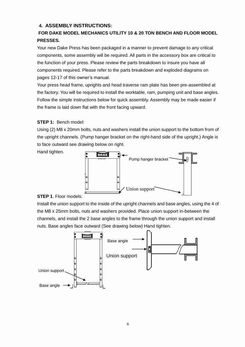
STEP 1: Bench model:
Using (2) M8 x 20mm bolts, nuts and washers install the union support to the bottom from of
the upright channels. (Pump hanger bracket on the right-hand side of the upright.) Angle is
to face outward see drawing below on right.
Hand tighten.
Pump hanger bracket
Union support
STEP 1. Floor models:
Install the union support to the inside of the upright channels and base angles, using the 4 of
the M8 x 25mm bolts, nuts and washers provided. Place union support in-between the
channels, and install the 2 base angles to the frame through the union support and install
nuts. Base angles face outward (See drawing below) Hand tighten.
Base angle
Union support
Union support
Base angle
7
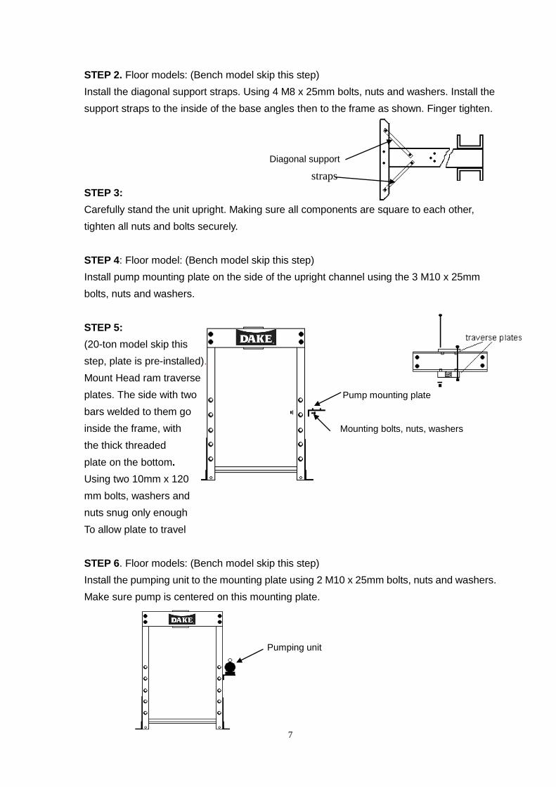
STEP 2. Floor models: (Bench model skip this step)
Install the diagonal support straps. Using 4 M8 x 25mm bolts, nuts and washers. Install the
support straps to the inside of the base angles then to the frame as shown. Finger tighten.
Diagonal support
straps
STEP 3:
Carefully stand the unit upright. Making sure all components are square to each other,
tighten all nuts and bolts securely.
STEP 4: Floor model: (Bench model skip this step)
Install pump mounting plate on the side of the upright channel using the 3 M10 x 25mm
bolts, nuts and washers.
STEP 5:
(20-ton model skip this
step, plate is pre-installed).
Mount Head ram traverse
plates. The side with two Pump mounting plate
bars welded to them go
inside the frame, with Mounting bolts, nuts, washers
the thick threaded
plate on the bottom.
Using two 10mm x 120
mm bolts, washers and
nuts snug only enough
To allow plate to travel
STEP 6. Floor models: (Bench model skip this step)
Install the pumping unit to the mounting plate using 2 M10 x 25mm bolts, nuts and washers.
Make sure pump is centered on this mounting plate.
Pumping unit

8
STEP 7:
With press standing upright and all bolts tightened install the worktable. Insert two table pins
in the two lowest holes. Take the worktable and tilt it at a sharp angle and insert it in the
uprights. (NOTE: The gussets welded to the table are at slight angles. The narrowest
dimension of these gussets go down. See drawing) (Step 1) Once worktable is in the
uprights turn it level and lower down and set it on the table pins. (Step 2) Take care when
doing this, a helper would be advised.
Gussets inside table
Step 1
Lower
Narrowest dimension
Step 2
STEP 8:
Locate the cylinder and remove the plastic protective cap on the end of the ram. (If
applicable) Carefully screw the cylinder from the top into the head traverse ram plate. Screw
this in as tight as possible while keeping the cylinder’s hydraulic hose fitting facing to the
right or pump side. (Cylinder may not be totally tight while keeping the fitting facing this way,
but it will not effect the presses operation.)
Using Teflon tape install the gauge to the Hose fitting
top of the cylinder facing forward.
When gauge and hose fittings Gauge
are in correct position install the
spanner nut on the bottom of cylinder
and snug up.
STEP 9:
On the bench model hang the pumping unit in its holder bracket on the side of the frame.
Remove the plastic protective cap from the end of the hydraulic hose. Screw the hydraulic
hose onto the cylinder hose fitting. The fitting has a knurled collar that you can tighten by
hand. (Do not use a wrench because damage may occur to the fitting) The hose has a check
valve that prevents oil from escaping so if hose is ever removed air will not get in the system.
9
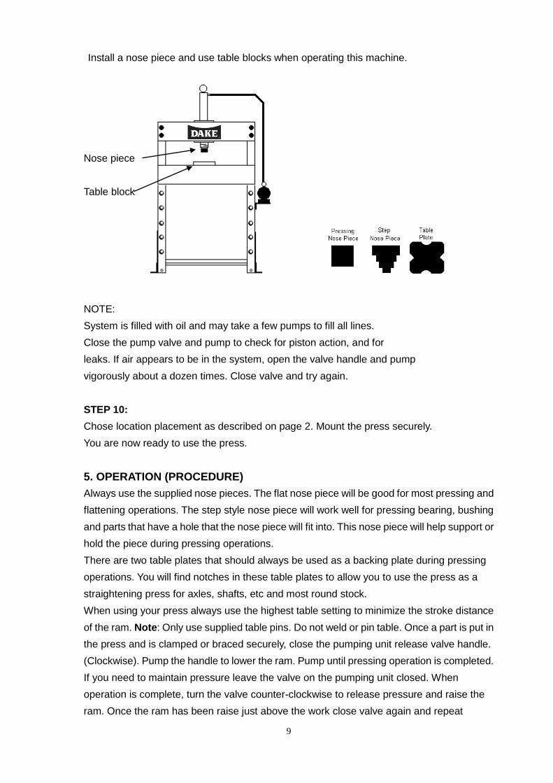
Install a nose piece and use table blocks when operating this machine.
Nose piece
Table block
NOTE:
System is filled with oil and may take a few pumps to fill all lines.
Close the pump valve and pump to check for piston action, and for
leaks. If air appears to be in the system, open the valve handle and pump
vigorously about a dozen times. Close valve and try again.
STEP 10:
Chose location placement as described on page 2. Mount the press securely.
You are now ready to use the press.
5. OPERATION (PROCEDURE)
Always use the supplied nose pieces. The flat nose piece will be good for most pressing and
flattening operations. The step style nose piece will work well for pressing bearing, bushing
and parts that have a hole that the nose piece will fit into. This nose piece will help support or
hold the piece during pressing operations.
There are two table plates that should always be used as a backing plate during pressing
operations. You will find notches in these table plates to allow you to use the press as a
straightening press for axles, shafts, etc and most round stock.
When using your press always use the highest table setting to minimize the stroke distance
of the ram. Note: Only use supplied table pins. Do not weld or pin table. Once a part is put in
the press and is clamped or braced securely, close the pumping unit release valve handle.
(Clockwise). Pump the handle to lower the ram. Pump until pressing operation is completed.
If you need to maintain pressure leave the valve on the pumping unit closed. When
operation is complete, turn the valve counter-clockwise to release pressure and raise the
ram. Once the ram has been raise just above the work close valve again and repeat
10
operation on the next part. There is no need to raise the ram all the way to the top each
time.
If pressing application requires a certain tonnage, press until the gauge reads the
appropriate tonnage then stop. Release pressure and repeat operation.
NOTE: Never pump the ram down fully and dead head the ram in the cylinder. Only build
pressure when using the table plates or a part is being pressed. Failure to do this may cause
ram seal damage and leaking.
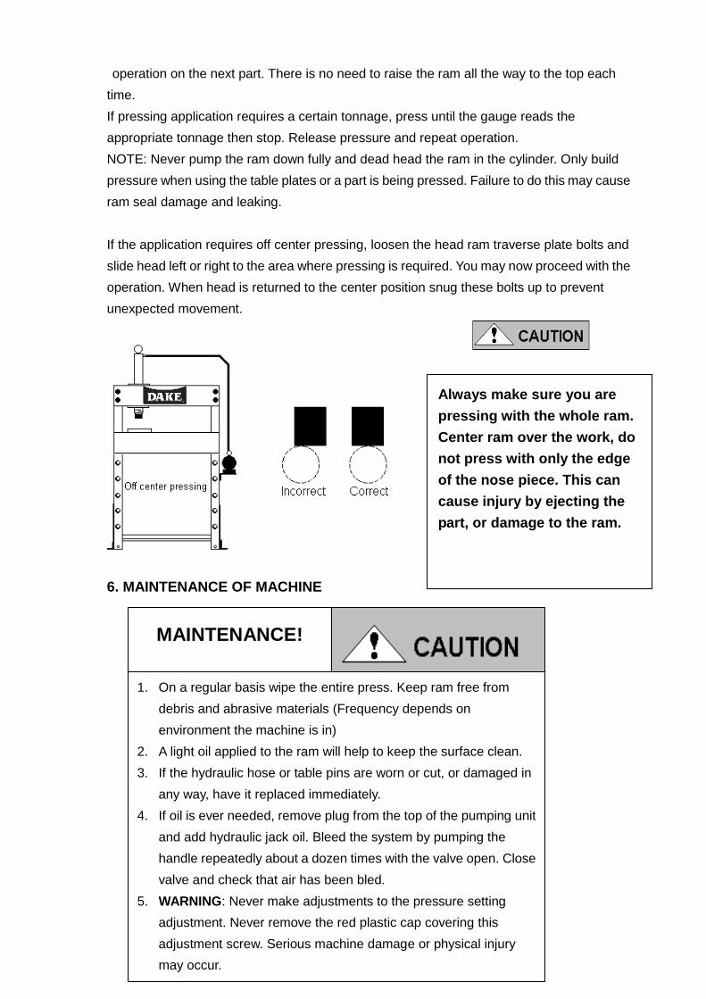
If the application requires off center pressing, loosen the head ram traverse plate bolts and
slide head left or right to the area where pressing is required. You may now proceed with the
operation. When head is returned to the center position snug these bolts up to prevent
unexpected movement.
Always make sure you are
pressing with the whole ram.
Center ram over the work, do
not press with only the edge
of the nose piece. This can
cause injury by ejecting the
part, or damage to the ram.
6. MAINTENANCE OF MACHINE
MAINTENANCE!
1. On a regular basis wipe the entire press. Keep ram free from
debris and abrasive materials (Frequency depends on
environment the machine is in)
2. A light oil applied to the ram will help to keep the surface clean.
3. If the hydraulic hose or table pins are worn or cut, or damaged in
any way, have it replaced immediately.
4. If oil is ever needed, remove plug from the top of the pumping unit
and add hydraulic jack oil. Bleed the system by pumping the
handle repeatedly about a dozen times with the valve open. Close
valve and check that air has been bled.
5. WARNING: Never make adjustments to the pressure setting
adjustment. Never remove the red plastic cap covering this
adjustment screw. Serious machine damage or physical injury
may occur.
11
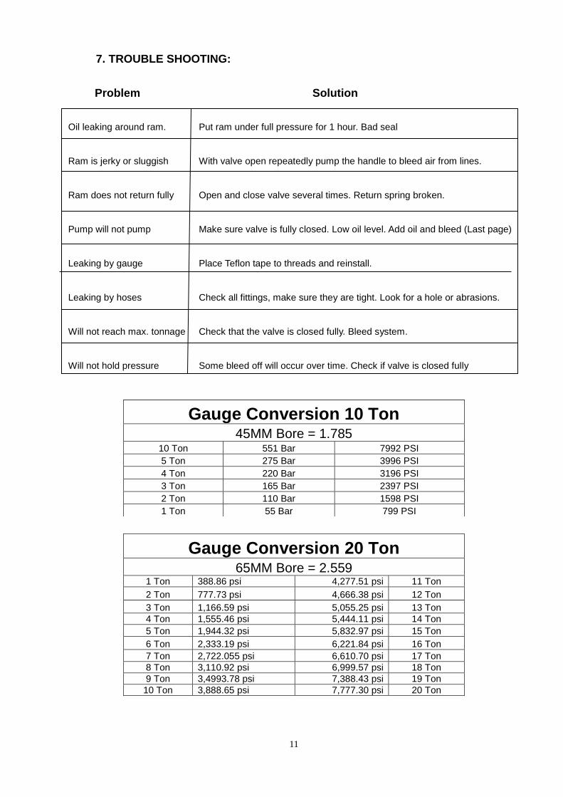
7. TROUBLE SHOOTING:
Problem Solution
Oil leaking around ram. Put ram under full pressure for 1 hour. Bad seal
Ram is jerky or sluggish With valve open repeatedly pump the handle to bleed air from lines.
Ram does not return fully Open and close valve several times. Return spring broken.
Pump will not pump Make sure valve is fully closed. Low oil level. Add oil and bleed (Last page)
Leaking by gauge Place Teflon tape to threads and reinstall.
Leaking by hoses Check all fittings, make sure they are tight. Look for a hole or abrasions.
Will not reach max. tonnage Check that the valve is closed fully. Bleed system.
Will not hold pressure Some bleed off will occur over time. Check if valve is closed fully
Gauge Conversion 10 Ton 45MM Bore = 1.785
10 Ton 551 Bar 7992 PSI
5 Ton 275 Bar 3996 PSI
4 Ton 220 Bar 3196 PSI
3 Ton 165 Bar 2397 PSI
2 Ton 110 Bar 1598 PSI
1 Ton 55 Bar 799 PSI
Gauge Conversion 20 Ton 65MM Bore = 2.559
1 Ton 388.86 psi 4,277.51 psi 11 Ton 2 Ton 777.73 psi 4,666.38 psi 12 Ton 3 Ton 1,166.59 psi 5,055.25 psi 13 Ton 4 Ton 1,555.46 psi 5,444.11 psi 14 Ton 5 Ton 1,944.32 psi 5,832.97 psi 15 Ton 6 Ton 2,333.19 psi 6,221.84 psi 16 Ton 7 Ton 2,722.055 psi 6,610.70 psi 17 Ton 8 Ton 3,110.92 psi 6,999.57 psi 18 Ton 9 Ton 3,4993.78 psi 7,388.43 psi 19 Ton 10 Ton 3,888.65 psi 7,777.30 psi 20 Ton

12
8. PARTS LIST
10 TON BENCH UTILITY PRESS PARTS LIST
Ref # Dake Part # Description Qty.
1 301139 Frame upright channel 2
2 301138 Head frame channel 2
3 / 19 301137 / 301133 Head ram traverse plates 1 upper & lower
4 301136 Bolt M12 x 110mm 6
5 301135 Lock washer 12mm 6
6 301134 Nut M12 x 4 6
7 301132 Union support 1
8 301131 Base angle 2
9 301130 Bolt M8 x 20 6
10 301129 Lock washer 8mm 6
11 301128 Nut M8 6
12 301127 Flat nose piece 1
13 301126 Step nose piece 1
14 301125 Table pin 2
15 301124 Table plate 2
16 301123 Work table 1
17 301122 Ram / Cylinder 1
17A 302382 Cylinder spring 1
18 301121 Pumping unit 1
20 301150 Bolt M10 x 140 2
21 302277 Washer 10mm 2
22 301149 Lock washer 10mm 2
23 301141 Nut 10mm 2
24 301120 Gauge 1
25 302276 Ring 1
Items not shown
302318 Cylinder Seal kit
302382 Spring for cylinder
302310 Fitting Nipple
302309 Fitting Coupler
302554 Pump repair kit
302508 Hydraulic hose w/Coupling
Spare seals should be stored in safe location out of direct sunlight.
When ordering, parts have model and date of purchase information ready.
For assistance call Dake Customer Service at 1-800-937-3253 or fax to 1-800-846-3253
e-mail to [email protected]
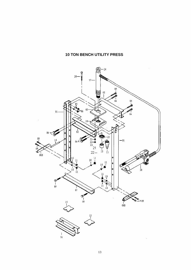
13
10 TON BENCH UTILITY PRESS

14
10 TON FLOOR UTILITY PRESS PARTS LIST
Ref # Dake Part # Description Qty.
1 301154 Frame upright channel 2
2 301153 Head frame channel 2
3 / 4 301152 / 301151 Head ram traverse plates 1 upper & lower
5 301150 Bolt M10 x 120mm 2
6 301149 Lock washer 10mm 2
7 301148 Union Support 1
8 301147 Base angle 2
9 301146 Bolt M8 x 25 12
10 301129 Lock washer 8mm 12
11 301128 Nut M8 12
12 301145 Angle support strap 4
13 301144 Pump support bracket 1
14 301143 Bolt M10 x 25 5
15 301142 Lock washer 10mm 4
16 301141 Nut M10 4
17 301123 Work table 1
18 301124 Table plate 2
19 301127 Flat nose piece (1-5/8 – 12) 1
20 301126 Step nose piece (1-5/8 – 12) 1
21 301140 Ram / Cylinder 1
21A 302383 Cylinder spring 1
22 301121 Pumping unit 1
23 301125 Table pin 2
24 301136 Bolt M12 x 110mm 4
25 301135 Lock washer 12mm 4
26 301134 Nut M12 4
27 302274 Bolt M8 x 25 4
28 301120 Gauge 1
29 302275 Ring 1
Items not shown
302318 Seal kit
302383 Cylinder spring
302310 Fitting Nipple
302309 Fitting Coupler
302554 Pump repair kit
302508 Hydraulic hose w/Coupling
Spare seals should be stored in safe location out of direct sunlight.
When ordering, parts have model and date of purchase information ready.
For assistance call Dake Customer Service at 1-800-937-3253 or fax to 1-800-846-3253
e-mail to [email protected]

15
10 TON FLOOR UTILITY PRESS
16
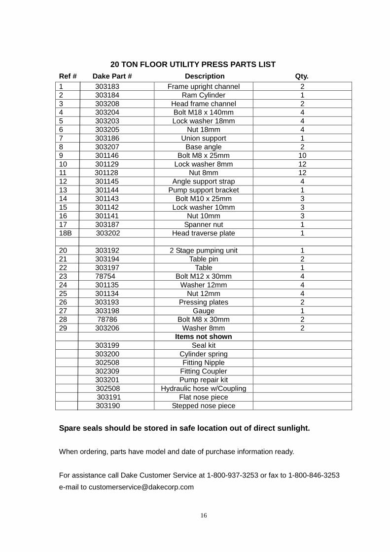
20 TON FLOOR UTILITY PRESS PARTS LIST
Ref # Dake Part # Description Qty.
1 303183 Frame upright channel 2
2 303184 Ram Cylinder 1
3 303208 Head frame channel 2
4 303204 Bolt M18 x 140mm 4
5 303203 Lock washer 18mm 4
6 303205 Nut 18mm 4
7 303186 Union support 1
8 303207 Base angle 2
9 301146 Bolt M8 x 25mm 10
10 301129 Lock washer 8mm 12
11 301128 Nut 8mm 12
12 301145 Angle support strap 4
13 301144 Pump support bracket 1
14 301143 Bolt M10 x 25mm 3
15 301142 Lock washer 10mm 3
16 301141 Nut 10mm 3
17 303187 Spanner nut 1
18B 303202 Head traverse plate 1
20 303192 2 Stage pumping unit 1
21 303194 Table pin 2
22 303197 Table 1
23 78754 Bolt M12 x 30mm 4
24 301135 Washer 12mm 4
25 301134 Nut 12mm 4
26 303193 Pressing plates 2
27 303198 Gauge 1
28 78786 Bolt M8 x 30mm 2
29 303206 Washer 8mm 2
Items not shown
303199 Seal kit
303200 Cylinder spring
302508 Fitting Nipple
302309 Fitting Coupler
303201 Pump repair kit
302508 Hydraulic hose w/Coupling
303191 Flat nose piece
303190 Stepped nose piece
Spare seals should be stored in safe location out of direct sunlight.
When ordering, parts have model and date of purchase information ready.
For assistance call Dake Customer Service at 1-800-937-3253 or fax to 1-800-846-3253
e-mail to [email protected]
17
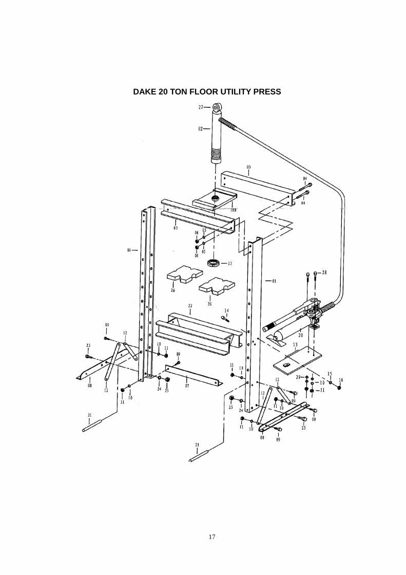
DAKE 20 TON FLOOR UTILITY PRESS
18
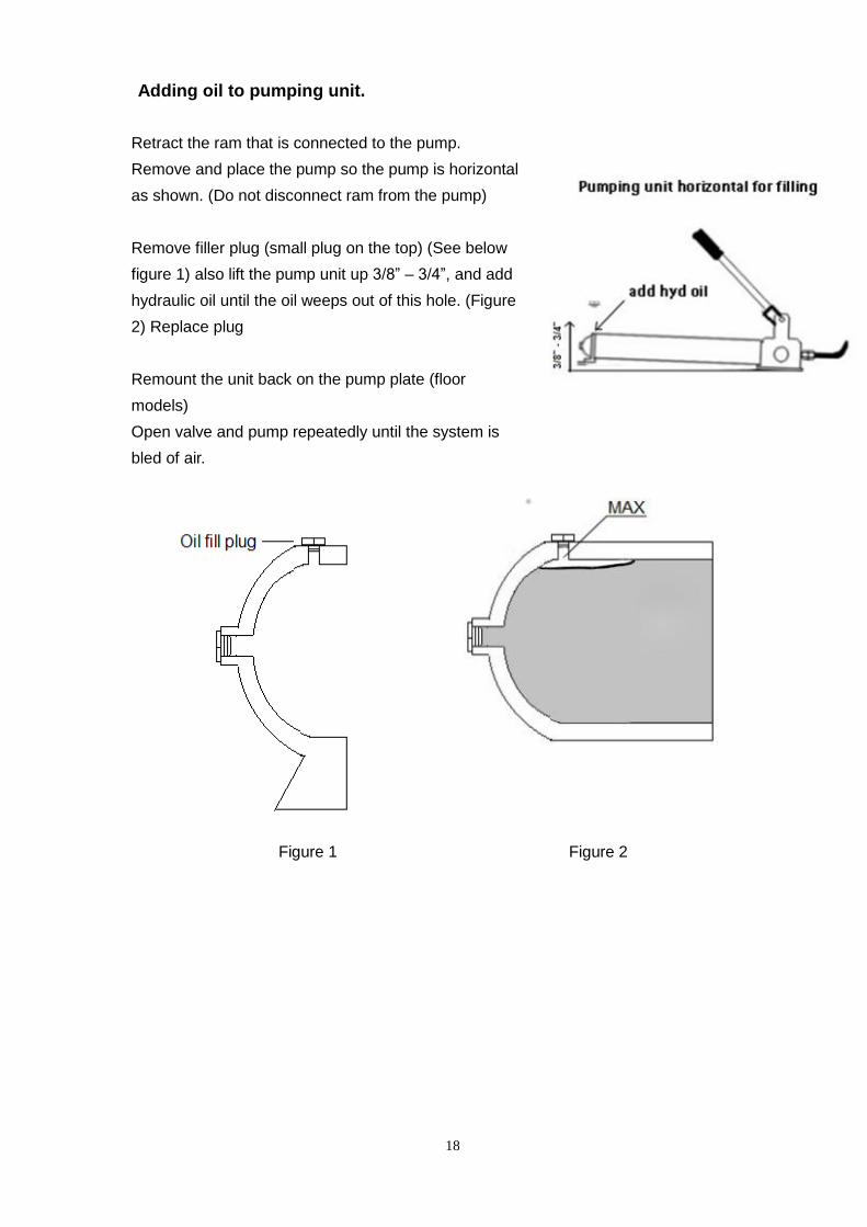
Adding oil to pumping unit.
Retract the ram that is connected to the pump.
Remove and place the pump so the pump is horizontal
as shown. (Do not disconnect ram from the pump)
Remove filler plug (small plug on the top) (See below
figure 1) also lift the pump unit up 3/8” – 3/4”, and add
hydraulic oil until the oil weeps out of this hole. (Figure
2) Replace plug
Remount the unit back on the pump plate (floor
models)
Open valve and pump repeatedly until the system is
bled of air.
Figure 1 Figure 2