Embed Size (px)
Citation preview
1
Zener barriers - operating instructionsOperating principle
Subject to reasonable modifications due to technical advances. Copyright Pepperl+Fuchs, Printed in Germany
Pepperl+Fuchs Group • Tel.: Germany +49 621 776-0 • USA +1 330 4253555 • Singapore +65 67799091 • Internet http://www.pepperl-fuchs.com
Dat
e of
issu
e05
/23/
03
1 Zener barriers - operating instructions Application
• Zener barriers are used in control and instrumentation systems for the processing of standardised signals, such as 20 mA and 10 V. Zener barriers contain intrinsically safe circuits that are used to drive intrinsically safe field devices within hazardous areas. The manufacturers data sheets must be consulted.
• The relevant regulations and directives governing the intended application must be observed.
Installation, commissioning
• Zener barriers are constructed to a protection classification of IP20 and accordingly must be appropriately protected from adverse conditions such as splashing water and soiling in excess of pollution severity 2.
• Zener barriers must be installed outside the hazardous area! Only those circuits identified as intrinsically safe may be located within the hazardous area.
• When intrinsically safe field devices are interconnected with the intrinsically safe circuits of the related Zener barriers, the respective highest values (safety parameters) for the field devices and the Zener barriers - in the sense of explosion protection - must be observed (demonstration of intrinsic safety). The EU certificate of conformity or EU prototype test certificate must be followed. Particular importance is attached to maintaining the "Special conditions" contained in these certificates.
• When intrinsically safe circuits are employed in an explosive dust atmosphere (zones 20 and 21), only appropriately certificated field devices are permitted to be incorporated.
Installation and commissioning within zone 2• The devices must be installed in switch boxes or distributor
boxes to protection category IP54 or better. • The devices may be installed within zone 2. Only those
circuits identified as intrinsically safe are permitted to be installed in zone 1 or zone 0 and in accordance with their ignition protection category approval. The actual installation of the intrinsically safe circuits is to be carried out in accordance with the applicable installation regulations.
• When interconnecting intrinsically safe field devices with the intrinsically safe circuits of the associated Zener barriers, the respective highest values (safety parameters) of the field device and the associated device, in the sense of explosion protection, must be taken into account (demonstration of intrinsic safety). The conditions stated on the EU certificates of conformity or EU prototype test certificates must be observed.
• In addition, for operation within zone 2, the statements of conformity of the certifying authorities/declarations of conformity of the manufacturer must be observed. Particular importance is attached to maintaining the "Special conditions" contained in these certificates.
• When intrinsically safe circuits are employed in an explosive dust atmosphere (zones 20 and 21), only appropriately certificated field devices are permitted to be incorporated.
Servicing and maintenance
The transmission characteristics of the devices remain stable over long periods, so that regular adjustments or other precautions are not required. This also means that no maintenance work is required.
Fault elimination
No modifications may be made to devices that are operated in connection with hazardous areas. Repairs must only be carried out by specially trained and authorised personnel.
1.1 Operating principle
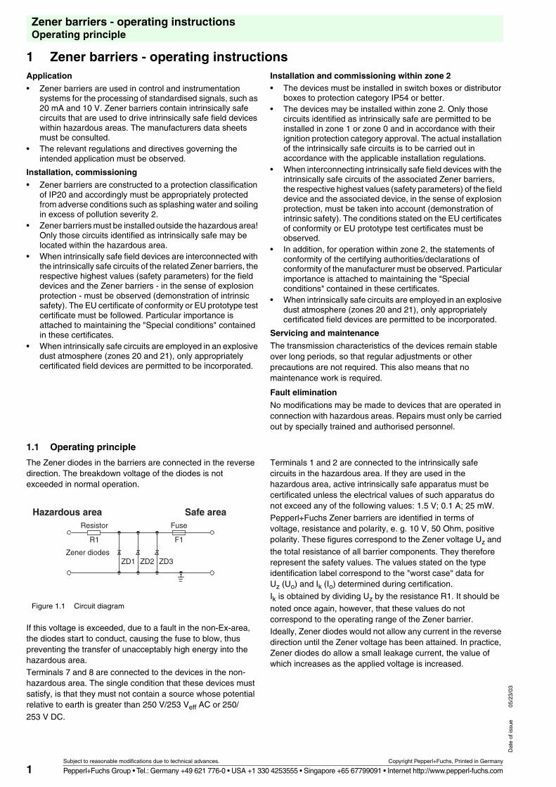
The Zener diodes in the barriers are connected in the reverse direction. The breakdown voltage of the diodes is not exceeded in normal operation.
Figure 1.1 Circuit diagram
If this voltage is exceeded, due to a fault in the non-Ex-area, the diodes start to conduct, causing the fuse to blow, thus preventing the transfer of unacceptably high energy into the hazardous area.Terminals 7 and 8 are connected to the devices in the non-hazardous area. The single condition that these devices must satisfy, is that they must not contain a source whose potential relative to earth is greater than 250 V/253 Veff AC or 250/
253 V DC.
Terminals 1 and 2 are connected to the intrinsically safe circuits in the hazardous area. If they are used in the hazardous area, active intrinsically safe apparatus must be certificated unless the electrical values of such apparatus do not exceed any of the following values: 1.5 V; 0.1 A; 25 mW.Pepperl+Fuchs Zener barriers are identified in terms of voltage, resistance and polarity, e. g. 10 V, 50 Ohm, positive polarity. These figures correspond to the Zener voltage Uz and
the total resistance of all barrier components. They therefore represent the safety values. The values stated on the type identification label correspond to the "worst case" data for Uz (Uo) and Ik (Io) determined during certification.
Ik is obtained by dividing Uz by the resistance R1. It should be
noted once again, however, that these values do not correspond to the operating range of the Zener barrier.Ideally, Zener diodes would not allow any current in the reverse direction until the Zener voltage has been attained. In practice, Zener diodes do allow a small leakage current, the value of which increases as the applied voltage is increased.
Hazardous area Safe area
ZD1Zener diodes
Resistor
R1
Fuse
F1
ZD2 ZD3
2
Zener barriers - operating instructionsOperating principle
Subject to reasonable modifications due to technical advances. Copyright Pepperl+Fuchs, Printed in Germany
Pepperl+Fuchs Group • Tel.: Germany +49 621 776-0 • USA +1 330 4253555 • Singapore +65 67799091 • Internet http://www.pepperl-fuchs.com
Dat
e of
issu
e05
/23/
03
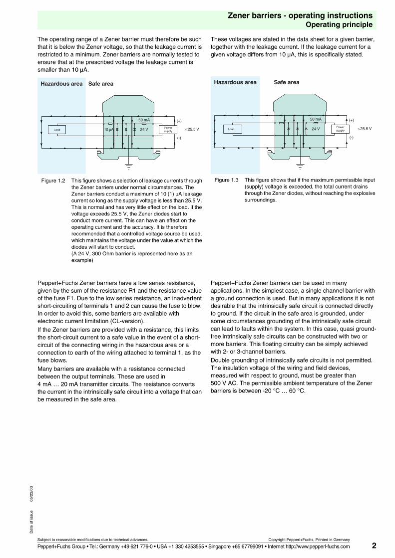
The operating range of a Zener barrier must therefore be such that it is below the Zener voltage, so that the leakage current is restricted to a minimum. Zener barriers are normally tested to ensure that at the prescribed voltage the leakage current is smaller than 10 µA.
Figure 1.2 This figure shows a selection of leakage currents through the Zener barriers under normal circumstances. The Zener barriers conduct a maximum of 10 (1) µA leakage current so long as the supply voltage is less than 25.5 V. This is normal and has very little effect on the load. If the voltage exceeds 25.5 V, the Zener diodes start to conduct more current. This can have an effect on the operating current and the accuracy. It is therefore recommended that a controlled voltage source be used, which maintains the voltage under the value at which the diodes will start to conduct.(A 24 V, 300 Ohm barrier is represented here as an example)
These voltages are stated in the data sheet for a given barrier, together with the leakage current. If the leakage current for a given voltage differs from 10 µA, this is specifically stated.
Figure 1.3 This figure shows that if the maximum permissible input (supply) voltage is exceeded, the total current drains through the Zener diodes, without reaching the explosive surroundings.
Pepperl+Fuchs Zener barriers have a low series resistance, given by the sum of the resistance R1 and the resistance value of the fuse F1. Due to the low series resistance, an inadvertent short-circuiting of terminals 1 and 2 can cause the fuse to blow. In order to avoid this, some barriers are available with electronic current limitation (CL-version).If the Zener barriers are provided with a resistance, this limits the short-circuit current to a safe value in the event of a short-circuit of the connecting wiring in the hazardous area or a connection to earth of the wiring attached to terminal 1, as the fuse blows.Many barriers are available with a resistance connected between the output terminals. These are used in 4 mA … 20 mA transmitter circuits. The resistance converts the current in the intrinsically safe circuit into a voltage that can be measured in the safe area.
Pepperl+Fuchs Zener barriers can be used in many applications. In the simplest case, a single channel barrier with a ground connection is used. But in many applications it is not desirable that the intrinsically safe circuit is connected directly to ground. If the circuit in the safe area is grounded, under some circumstances grounding of the intrinsically safe circuit can lead to faults within the system. In this case, quasi ground-free intrinsically safe circuits can be constructed with two or more barriers. This floating circuitry can be simply achieved with 2- or 3-channel barriers.
Double grounding of intrinsically safe circuits is not permitted. The insulation voltage of the wiring and field devices, measured with respect to ground, must be greater than 500 V AC. The permissible ambient temperature of the Zener barriers is between -20 °C … 60 °C.
Powersupply
Hazardous area Safe area
Load ≤25.5 V
50 mA
24 V
(+)
(-)
10 µAPowersupply
Hazardous area Safe area
Load >25.5 V
50 mA
24 V
(+)
(-)
3
Zener barriers - operating instructionsMulti-channel barriers
Subject to reasonable modifications due to technical advances. Copyright Pepperl+Fuchs, Printed in Germany
Pepperl+Fuchs Group • Tel.: Germany +49 621 776-0 • USA +1 330 4253555 • Singapore +65 67799091 • Internet http://www.pepperl-fuchs.com
Dat
e of
issu
e05
/23/
03
1.2 Multi-channel barriers
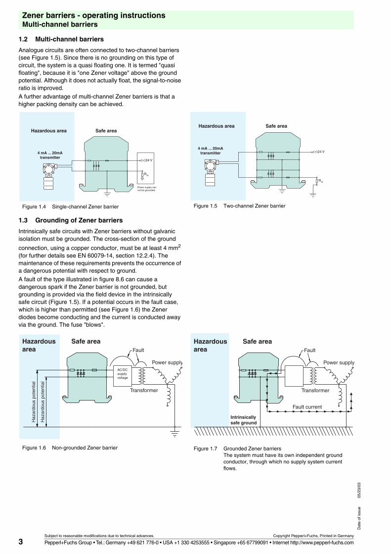
Analogue circuits are often connected to two-channel barriers (see Figure 1.5). Since there is no grounding on this type of circuit, the system is a quasi floating one. It is termed "quasi floating", because it is "one Zener voltage" above the ground potential. Although it does not actually float, the signal-to-noise ratio is improved.A further advantage of multi-channel Zener barriers is that a higher packing density can be achieved..
Figure 1.4 Single-channel Zener barrier Figure 1.5 Two-channel Zener barrier
1.3 Grounding of Zener barriers
Intrinsically safe circuits with Zener barriers without galvanic isolation must be grounded. The cross-section of the ground
connection, using a copper conductor, must be at least 4 mm2 (for further details see EN 60079-14, section 12.2.4). The maintenance of these requirements prevents the occurrence of a dangerous potential with respect to ground.
A fault of the type illustrated in figure 8.6 can cause a dangerous spark if the Zener barrier is not grounded, but grounding is provided via the field device in the intrinsically safe circuit (Figure 1.5). If a potential occurs in the fault case, which is higher than permitted (see Figure 1.6) the Zener diodes become conducting and the current is conducted away via the ground. The fuse "blows"..
Figure 1.6 Non-grounded Zener barrier Figure 1.7 Grounded Zener barriers The system must have its own independent ground conductor, through which no supply system current flows.
Power supply cannot be grounded.
Hazardous area
4 mA ... 20mAtransmitter
Safe area
24 V
RM
(+)
Hazardous area
4 mA ... 20mAtransmitter
Safe area
24 V
RM
(+)
Fault
Transformer
Haz
ardo
us p
oten
tial
Haz
ardo
us p
oten
tial
Power supplyAC/DCsupply voltage
Hazardous area
Safe areaFault
Transformer
Power supply
Hazardous area
Safe area
Fault current
Intrinsicallysafe ground
4
Zener barriers - operating instructionsInstallation notes
Subject to reasonable modifications due to technical advances. Copyright Pepperl+Fuchs, Printed in Germany
Pepperl+Fuchs Group • Tel.: Germany +49 621 776-0 • USA +1 330 4253555 • Singapore +65 67799091 • Internet http://www.pepperl-fuchs.com
Dat
e of
issu
e05
/23/
03
1.4 Installation notes
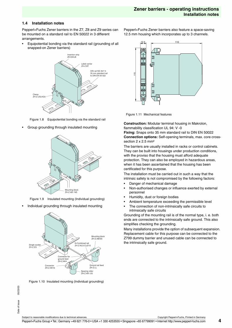
Pepperl+Fuchs Zener barriers in the Z7, Z8 and Z9 series can be mounted on a standard rail to EN 50022 in 3 different arrangements.
• Equipotential bonding via the standard rail (grounding of all snapped-on Zener barriers)
• Group grounding through insulated mounting
• Individual grounding through insulated mounting
Pepperl+Fuchs Zener barriers also feature a space-saving 12.5 mm housing which incorporates up to 3 channels.
Figure 1.11 Mechanical features
Construction: Modular terminal housing in Makrolon, flammability classification UL 94: V -0Fixing: Snaps onto 35 mm standard rail to DIN EN 50022Connection options: Self-opening terminals, max. core cross-section 2 x 2.5 mm²
The barriers are usually installed in racks or control cabinets. They can be built into housings under production conditions, with the proviso that the housing must afford adequate protection. They can also be employed in hazardous areas, when it has been ascertained that the housing has been certificated for this purpose. The installation must be carried out in such a way that the intrinsic safety is not compromised by the following factors:• Danger of mechanical damage• Non-authorised changes or influence exerted by external
personnel• Humidity, dust or foreign bodies• Ambient temperature exceeding the permissible level• The connection of non-intrinsically safe circuits to
intrinsically safe circuitsGrounding of the mounting rail is of the normal type, i. e. both ends are connected to the intrinsically safe ground. This also simplifies checking the grounding.Many installations provide the option of subsequent expansion. Replacement cable for this purpose can be connected to the Z799 dummy barrier and unused cable can be connected to the intrinsically safe ground.
Figure 1.8 Equipotential bonding via the standard rail
Insertion stripZH-ES/LB
ClampZH-Z.USLKG5
Label carrierZH-Z.BT
DIN rail NS 35/7.535 mm standard railto DIN EN 50 022
Mounting blockZH-Z.AB / NS
Figure 1.9 Insulated mounting (Individual grounding)
Single socketZH-Z.ES
Connector for ground leadZH-Z.AK4
ConnectorZH-Z.AK16
Mounting blockZH-Z.AB/SS
Ground rail feedZH-Z.LL
N-Combined railZH-Z.NLS-Cu3/10
Spacing rollerZH-Z.AR.125
Figure 1.10 Insulated mounting (Individual grounding)
11012.5
115
5
Zener barriers - operating instructionsZener barrier specifications
Subject to reasonable modifications due to technical advances. Copyright Pepperl+Fuchs, Printed in Germany
Pepperl+Fuchs Group • Tel.: Germany +49 621 776-0 • USA +1 330 4253555 • Singapore +65 67799091 • Internet http://www.pepperl-fuchs.com
Dat
e of
issu
e05
/23/
03
1.5 Zener barrier specifications
Nominal data
The following are typical data used in the description of a barrier:28 V, 300 Ohm, 93 mA. These values relate to the maximum voltage, the minimum value of the built-in resistance and the resulting maximum current.
The maximum voltage stated is not representative of the operating range, it is the maximum value that can be attained in a failure case, before the fuse responds. The resistance value is not identical to the maximum series resistance. These values merely provide an indication of the maximum values that can apply in the case of a failure.
Series resistance
This is the resistance that can be measured between the two ends of a barrier channel. It is obtained from the sum of the resistance R and resistance value of the fuse at an ambient temperature of 20 °C.
Polarity
Zener barriers are available in various versions. On Zener barriers for positive polarities the anodes of the Zener diodes are grounded. On barriers for negative polarities it is the cathodes which are grounded. On barriers for alternating polarities, interconnected Zener diodes are employed and one side is grounded. These can be used for both alternating voltage signals and direct voltage signals.
Maximum voltage in the intrinsically safe circuit. (Uz)
This is the maximum value of voltage that can occur in the intrinsically safe circuit in the failure case.
Maximum current in the intrinsically safe circuit (Ik)
This is the maximum current that can flow in the intrinsically safe circuit in the failure case.
Maximum input voltage (max. Uin)
The maximum voltage (correct polarity) that can be applied between the contacts in the safe area and the ground without the fuse responding. This value is determined for an open intrinsically safe circuit and an ambient temperature of 20 °C.
Input voltage (Uin at 10 (1) µA)
The maximum voltage (correct polarity) that can be applied between the contacts in the safe area and the ground at a defined leakage current (as a rule 10 µA). This is the upper value of the recommended operating range.
Maximum connectable external capacitance Cmax
This is the maximum capacitance that can be connected to the terminals of the barrier intrinsically safe circuit. This value is determined from the sum of the wiring capacitance and the input capacitance of the field device.
Maximum connectable external inductance Lmax
This is the maximum inductance that can be connected to the terminals of the barrier intrinsically safe circuit. The value is determined from the sum of the inductance of the wiring and the input inductance of the field device.
Note:The designations of the values given in the specifications above are not those of the relevant standards, but those specified on certificates of conformity (e. g. in EN 60079-14, Section 3, IK is now IO).
1.6 How to select the correct barrier
For very many applications the standard solutions are given in this catalogue, in the section on Example Applications. However, in the event that a particular application has not been covered, the following information may be helpful.
1. First decide whether it will be necessary to have a floating circuit, or whether the intrinsically safe circuit can be connected directly to ground. Check whether any existing instrumentation is grounded. If the answer is yes, then check whether additional grounding could lead to faults. Bear in mind that the floating circuit offers a better common-mode rejection characteristic than the grounded circuit. On the other hand, it is more expensive. If a floating circuit is employed, the barriers will normally resist a ground fault.
2. Select the required polarity. This is either determined by the circuit itself, or by any other existing grounds in the circuit. In most applications barriers for positive polarities are used. In order to achieve greater system standardisation, barriers suitable for alternating polarities can be used in place of unipolar ones.
3. Decide the nominal voltage of the Zener barrier. Then determine the maximum output voltage of the device in the safe area during normal operation. Normally the required value is the next highest nominal voltage of a Zener barrier. If these values are close together, it could be that the
recommended operating range of the Zener barrier is exceeded. The consequence of this is that the leakage current will be greater than 10 µA. In this case a barrier with a higher nominal voltage should be used. The leakage current is determined for an open intrinsically safe circuit and this then represents the maximum value at the given voltage.
4. Take account of the maximum series resistance of the Zener barrier and its effect on the intrinsically safe circuit. Make sure that this resistance does not cause an inadmissibly high loss of voltage. In circuits having high resistance - usually when voltage signals are being transferred - this resistance is not relevant. If for example a barrier has a max. series resistance of 1 kOhm, then the resulting error is 0.1 %, if the input resistance of the connected device is 1 MOhm.
5. Check whether or not the field device must be certificated for use in the hazardous area. If certification is necessary, check what the prerequisites are for permitting the field device to be used in connection with a Zener barrier.
6. What is the overall length of the cabling between the voltage supply and the field device? Note the number of conductors in the system!
6
Zener barriers - operating instructionsHow to select the correct barrier
Subject to reasonable modifications due to technical advances. Copyright Pepperl+Fuchs, Printed in Germany
Pepperl+Fuchs Group • Tel.: Germany +49 621 776-0 • USA +1 330 4253555 • Singapore +65 67799091 • Internet http://www.pepperl-fuchs.com
Dat
e of
issu
e05
/23/
03
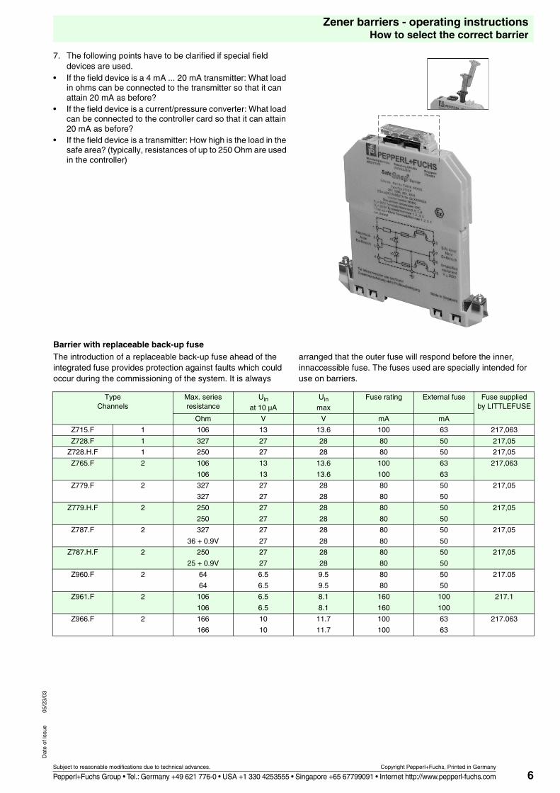
7. The following points have to be clarified if special field devices are used.
• If the field device is a 4 mA ... 20 mA transmitter: What load in ohms can be connected to the transmitter so that it can attain 20 mA as before?
• If the field device is a current/pressure converter: What load can be connected to the controller card so that it can attain 20 mA as before?
• If the field device is a transmitter: How high is the load in the safe area? (typically, resistances of up to 250 Ohm are used in the controller)
Z ...
Barrier with replaceable back-up fuseThe introduction of a replaceable back-up fuse ahead of the integrated fuse provides protection against faults which could occur during the commissioning of the system. It is always
arranged that the outer fuse will respond before the inner, innaccessible fuse. The fuses used are specially intended for use on barriers.
TypeChannels
Max. series resistance
Uin
at 10 µA
Uin
max
Fuse rating External fuse Fuse supplied by LITTLEFUSE
Ohm V V mA mA
Z715.F 1 106 13 13.6 100 63 217,063
Z728.F 1 327 27 28 80 50 217,05
Z728.H.F 1 250 27 28 80 50 217,05
Z765.F 2 106
106
13
13
13.6
13.6
100
100
63
63
217,063
Z779.F 2 327
327
27
27
28
28
80
80
50
50
217,05
Z779.H.F 2 250
250
27
27
28
28
80
80
50
50
217,05
Z787.F 2 327
36 + 0.9V
27
27
28
28
80
80
50
50
217,05
Z787.H.F 2 250
25 + 0.9V
27
27
28
28
80
80
50
50
217,05
Z960.F 2 64
64
6.5
6.5
9.5
9.5
80
80
50
50
217.05
Z961.F 2 106
106
6.5
6.5
8.1
8.1
160
160
100
100
217.1
Z966.F 2 166
166
10
10
11.7
11.7
100
100
63
63
217.063
7
Zener barriers - operating instructionsHow to select the correct barrier
Subject to reasonable modifications due to technical advances. Copyright Pepperl+Fuchs, Printed in Germany
Pepperl+Fuchs Group • Tel.: Germany +49 621 776-0 • USA +1 330 4253555 • Singapore +65 67799091 • Internet http://www.pepperl-fuchs.com
Dat
e of
issu
e05
/23/
03
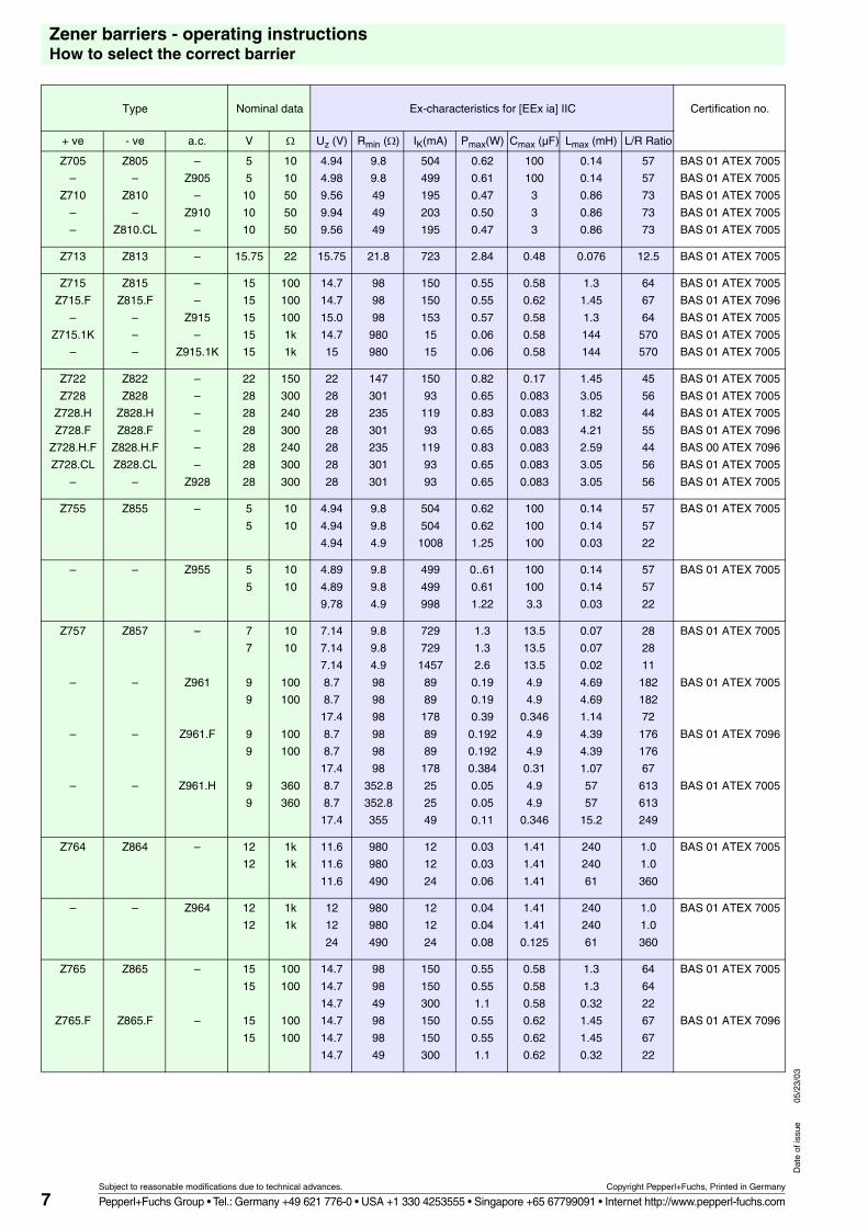
Type Nominal data Ex-characteristics for [EEx ia] IIC Certification no.
+ ve - ve a.c. V � Uz (V) Rmin (�) IK(mA) Pmax(W) Cmax (µF) Lmax (mH) L/R Ratio
Z705
–
Z710
–
–
Z805
–
Z810
–
Z810.CL
–
Z905
–
Z910
–
5
5
10
10
10
10
10
50
50
50
4.94
4.98
9.56
9.94
9.56
9.8
9.8
49
49
49
504
499
195
203
195
0.62
0.61
0.47
0.50
0.47
100
100
3
3
3
0.14
0.14
0.86
0.86
0.86
57
57
73
73
73
BAS 01 ATEX 7005
BAS 01 ATEX 7005
BAS 01 ATEX 7005
BAS 01 ATEX 7005
BAS 01 ATEX 7005
Z713 Z813 – 15.75 22 15.75 21.8 723 2.84 0.48 0.076 12.5 BAS 01 ATEX 7005
Z715
Z715.F
–
Z715.1K
–
Z815
Z815.F
–
–
–
–
–
Z915
–
Z915.1K
15
15
15
15
15
100
100
100
1k
1k
14.7
14.7
15.0
14.7
15
98
98
98
980
980
150
150
153
15
15
0.55
0.55
0.57
0.06
0.06
0.58
0.62
0.58
0.58
0.58
1.3
1.45
1.3
144
144
64
67
64
570
570
BAS 01 ATEX 7005
BAS 01 ATEX 7096
BAS 01 ATEX 7005
BAS 01 ATEX 7005
BAS 01 ATEX 7005
Z722
Z728
Z728.H
Z728.F
Z728.H.F
Z728.CL
–
Z822
Z828
Z828.H
Z828.F
Z828.H.F
Z828.CL
–
–
–
–
–
–
–
Z928
22
28
28
28
28
28
28
150
300
240
300
240
300
300
22
28
28
28
28
28
28
147
301
235
301
235
301
301
150
93
119
93
119
93
93
0.82
0.65
0.83
0.65
0.83
0.65
0.65
0.17
0.083
0.083
0.083
0.083
0.083
0.083
1.45
3.05
1.82
4.21
2.59
3.05
3.05
45
56
44
55
44
56
56
BAS 01 ATEX 7005
BAS 01 ATEX 7005
BAS 01 ATEX 7005
BAS 01 ATEX 7096
BAS 00 ATEX 7096
BAS 01 ATEX 7005
BAS 01 ATEX 7005
Z755 Z855 – 5
5
10
10
4.94
4.94
4.94
9.8
9.8
4.9
504
504
1008
0.62
0.62
1.25
100
100
100
0.14
0.14
0.03
57
57
22
BAS 01 ATEX 7005
– – Z955 5
5
10
10
4.89
4.89
9.78
9.8
9.8
4.9
499
499
998
0..61
0.61
1.22
100
100
3.3
0.14
0.14
0.03
57
57
22
BAS 01 ATEX 7005
Z757
–
–
–
Z857
–
–
–
–
Z961
Z961.F
Z961.H
7
7
9
9
9
9
9
9
10
10
100
100
100
100
360
360
7.14
7.14
7.14
8.7
8.7
17.4
8.7
8.7
17.4
8.7
8.7
17.4
9.8
9.8
4.9
98
98
98
98
98
98
352.8
352.8
355
729
729
1457
89
89
178
89
89
178
25
25
49
1.3
1.3
2.6
0.19
0.19
0.39
0.192
0.192
0.384
0.05
0.05
0.11
13.5
13.5
13.5
4.9
4.9
0.346
4.9
4.9
0.31
4.9
4.9
0.346
0.07
0.07
0.02
4.69
4.69
1.14
4.39
4.39
1.07
57
57
15.2
28
28
11
182
182
72
176
176
67
613
613
249
BAS 01 ATEX 7005
BAS 01 ATEX 7005
BAS 01 ATEX 7096
BAS 01 ATEX 7005
Z764 Z864 – 12
12
1k
1k
11.6
11.6
11.6
980
980
490
12
12
24
0.03
0.03
0.06
1.41
1.41
1.41
240
240
61
1.0
1.0
360
BAS 01 ATEX 7005
– – Z964 12
12
1k
1k
12
12
24
980
980
490
12
12
24
0.04
0.04
0.08
1.41
1.41
0.125
240
240
61
1.0
1.0
360
BAS 01 ATEX 7005
Z765
Z765.F
Z865
Z865.F
–
–
15
15
15
15
100
100
100
100
14.7
14.7
14.7
14.7
14.7
14.7
98
98
49
98
98
49
150
150
300
150
150
300
0.55
0.55
1.1
0.55
0.55
1.1
0.58
0.58
0.58
0.62
0.62
0.62
1.3
1.3
0.32
1.45
1.45
0.32
64
64
22
67
67
22
BAS 01 ATEX 7005
BAS 01 ATEX 7096
8
Zener barriers - operating instructionsHow to select the correct barrier
Subject to reasonable modifications due to technical advances. Copyright Pepperl+Fuchs, Printed in Germany
Pepperl+Fuchs Group • Tel.: Germany +49 621 776-0 • USA +1 330 4253555 • Singapore +65 67799091 • Internet http://www.pepperl-fuchs.com
Dat
e of
issu
e05
/23/
03
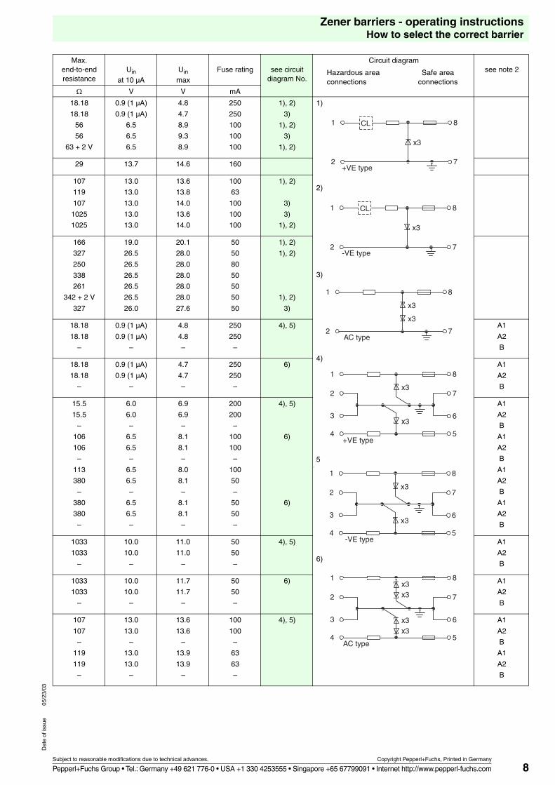
Max.end-to-end resistance
Uin
at 10 µA
Uin
max
Fuse rating see circuitdiagram No.
Circuit diagram
Hazardous area Safe areaconnections connections
see note 2
� V V mA
18.18
18.18
56
56
63 + 2 V
0.9 (1 µA)
0.9 (1 µA)
6.5
6.5
6.5
4.8
4.7
8.9
9.3
8.9
250
250
100
100
100
1), 2)
3)
1), 2)
3)
1), 2)
1)
2)
3)
4)
5)
6)
29 13.7 14.6 160
107
119
107
1025
1025
13.0
13.0
13.0
13.0
13.0
13.6
13.8
14.0
13.6
14.0
100
63
100
100
100
1), 2)
3)
3)
1), 2)
166
327
250
338
261
342 + 2 V
327
19.0
26.5
26.5
26.5
26.5
26.5
26.0
20.1
28.0
28.0
28.0
28.0
28.0
27.6
50
50
80
50
50
50
50
1), 2)
1), 2)
1), 2)
3)
18.18
18.18
–
0.9 (1 µA)
0.9 (1 µA)
–
4.8
4.8
–
250
250
–
4), 5) A1
A2
B
18.18
18.18
–
0.9 (1 µA)
0.9 (1 µA)
–
4.7
4.7
–
250
250
–
6) A1
A2
B
15.5
15.5
–
106
106
–
113
380
–
380
380
–
6.0
6.0
–
6.5
6.5
–
6.5
6.5
–
6.5
6.5
–
6.9
6.9
–
8.1
8.1
–
8.0
8.1
–
8.1
8.1
–
200
200
–
100
100
–
100
50
–
50
50
–
4), 5)
6)
6)
A1
A2
B
A1
A2
B
A1
A2
B
A1
A2
B
1033
1033
–
10.0
10.0
–
11.0
11.0
–
50
50
–
4), 5) A1
A2
B
1033
1033
–
10.0
10.0
–
11.7
11.7
–
50
50
–
6) A1
A2
B
107
107
–
119
119
–
13.0
13.0
–
13.0
13.0
–
13.6
13.6
–
13.9
13.9
–
100
100
–
63
63
–
4), 5) A1
A2
B
A1
A2
B
+VE type
1 8
2 7
CL
x3
-VE type
1 8
2 7
CL
x3
AC type
1 8
2 7
x3
x3
+VE type
1 8
4 5
2 7
3 6x3
x3
-VE type
1 8
4 5
2 7
3 6x3
x3
AC type
1 8
4 5
2 7
3 6
x3x3
x3x3
9
Zener barriers - operating instructionsHow to select the correct barrier
Subject to reasonable modifications due to technical advances. Copyright Pepperl+Fuchs, Printed in Germany
Pepperl+Fuchs Group • Tel.: Germany +49 621 776-0 • USA +1 330 4253555 • Singapore +65 67799091 • Internet http://www.pepperl-fuchs.com
Dat
e of
issu
e05
/23/
03
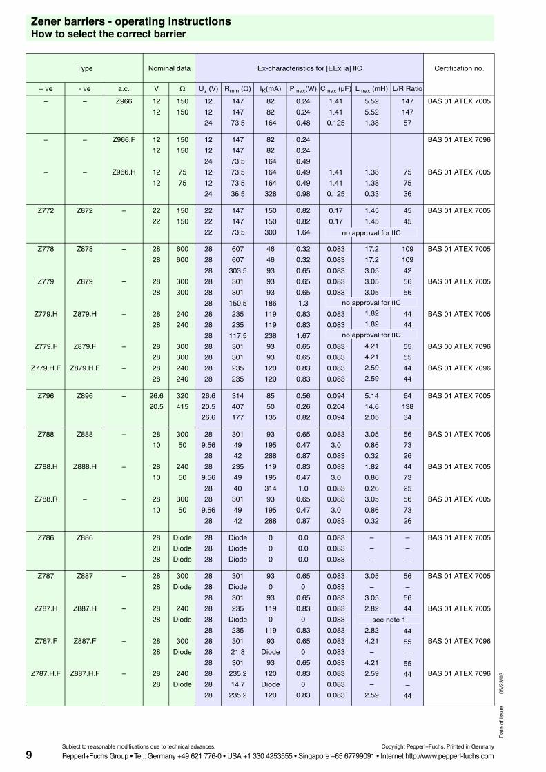
Type Nominal data Ex-characteristics for [EEx ia] IIC Certification no.
+ ve - ve a.c. V � Uz (V) Rmin (�) IK(mA) Pmax(W) Cmax (µF) Lmax (mH) L/R Ratio
– – Z966 12
12
150
150
12
12
24
147
147
73.5
82
82
164
0.24
0.24
0.48
1.41
1.41
0.125
5.52
5.52
1.38
147
147
57
BAS 01 ATEX 7005
–
–
–
–
Z966.F
Z966.H
12
12
12
12
150
150
75
75
12
12
24
12
12
24
147
147
73.5
73.5
73.5
36.5
82
82
164
164
164
328
0.24
0.24
0.49
0.49
0.49
0.98
1.41
1.41
0.125
1.38
1.38
0.33
75
75
36
BAS 01 ATEX 7096
BAS 01 ATEX 7005
Z772 Z872 – 22
22
150
150
22
22
22
147
147
73.5
150
150
300
0.82
0.82
1.64
0.17
0.17
1.45
1.45
45
45
BAS 01 ATEX 7005
Z778
Z779
Z779.H
Z779.F
Z779.H.F
Z878
Z879
Z879.H
Z879.F
Z879.H.F
–
–
–
–
–
28
28
28
28
28
28
28
28
28
28
600
600
300
300
240
240
300
300
240
240
28
28
28
28
28
28
28
28
28
28
28
28
28
607
607
303.5
301
301
150.5
235
235
117.5
301
301
235
235
46
46
93
93
93
186
119
119
238
93
93
120
120
0.32
0.32
0.65
0.65
0.65
1.3
0.83
0.83
1.67
0.65
0.65
0.83
0.83
0.083
0.083
0.083
0.083
0.083
0.083
0.083
0.083
0.083
0.083
0.083
17.2
17.2
3.05
3.05
3.05
1.82
1.82
4.21
4.21
2.59
2.59
109
109
42
56
56
44
44
55
55
44
44
BAS 01 ATEX 7005
BAS 01 ATEX 7005
BAS 01 ATEX 7005
BAS 00 ATEX 7096
BAS 01 ATEX 7096
Z796 Z896 – 26.6
20.5
320
415
26.6
20.5
26.6
314
407
177
85
50
135
0.56
0.26
0.82
0.094
0.204
0.094
5.14
14.6
2.05
64
138
34
BAS 01 ATEX 7005
Z788
Z788.H
Z788.R
Z888
Z888.H
–
–
–
–
28
10
28
10
28
10
300
50
240
50
300
50
28
9.56
28
28
9.56
28
28
9.56
28
301
49
42
235
49
40
301
49
42
93
195
288
119
195
314
93
195
288
0.65
0.47
0.87
0.83
0.47
1.0
0.65
0.47
0.87
0.083
3.0
0.083
0.083
3.0
0.083
0.083
3.0
0.083
3.05
0.86
0.32
1.82
0.86
0.26
3.05
0.86
0.32
56
73
26
44
73
25
56
73
26
BAS 01 ATEX 7005
BAS 01 ATEX 7005
BAS 01 ATEX 7005
Z786 Z886 28
28
28
Diode
Diode
Diode
28
28
28
Diode
Diode
Diode
0
0
0
0.0
0.0
0.0
0.083
0.083
0.083
–
–
–
–
–
–
BAS 01 ATEX 7005
Z787
Z787.H
Z787.F
Z787.H.F
Z887
Z887.H
Z887.F
Z887.H.F
–
–
–
–
28
28
28
28
28
28
28
28
300
Diode
240
Diode
300
Diode
240
Diode
28
28
28
28
28
28
28
28
28
28
28
28
301
Diode
301
235
Diode
235
301
21.8
301
235.2
14.7
235.2
93
0
93
119
0
119
93
Diode
93
120
Diode
120
0.65
0
0.65
0.83
0
0.83
0.65
0
0.65
0.83
0
0.83
0.083
0.083
0.083
0.083
0.083
0.083
0.083
0.083
0.083
0.083
0.083
0.083
3.05
–
3.05
2.82
2.82
4.21
–
4.21
2.59
–
2.59
56
–
56
44
44
55
–
55
44
–
44
BAS 01 ATEX 7005
BAS 01 ATEX 7005
BAS 01 ATEX 7096
BAS 01 ATEX 7096
no approval for IIC
no approval for IIC
no approval for IIC
see note 1
10
Zener barriers - operating instructionsHow to select the correct barrier
Subject to reasonable modifications due to technical advances. Copyright Pepperl+Fuchs, Printed in Germany
Pepperl+Fuchs Group • Tel.: Germany +49 621 776-0 • USA +1 330 4253555 • Singapore +65 67799091 • Internet http://www.pepperl-fuchs.com
Dat
e of
issu
e05
/23/
03
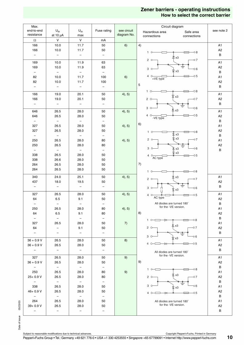
Max.end-to-end resistance
Uin
at 10 µA
Uin
max
Fuse rating see circuitdiagram No.
Circuit diagram
Hazardous area Safe areaconnections connections
see note 2
� V V mA
166
166
–
10.0
10.0
–
11.7
11.7
–
50
50
–
6) 4)
5)
6)
7)
8)
9)
A1
A2
B
169
169
–
82
82
–
10.0
10.0
–
10.0
10.0
–
11.9
11.9
–
11.7
11.7
–
63
63
–
100
100
–
6)
A1
A2
B
A1
A2
B
166
166
–
19.0
19.0
–
20.1
20.1
–
50
50
–
4), 5) A1
A2
B
646
646
–
327
327
–
250
250
–
338
338
264
264
26.5
26.5
–
26.5
26.5
–
26.5
26.5
–
26.5
26.6
26.5
26.5
28.0
28.0
–
28.0
28.0
–
28.0
28.0
–
28.0
28.0
28.0
28.0
50
50
–
50
50
–
80
80
–
50
50
50
50
4), 5)
4), 5)
4), 5)
A1
A2
B
A1
A2
B
A1
A2
B
340
437
–
24.0
18.0
–
25.1
19.5
–
50
50
–
4), 5) A1
A2
B
327
64
–
250
64
–
327
64
–
26.5
6.5
–
26.5
6.5
–
26.5
–
–
28.0
9.1
–
28.0
9.1
–
28.0
9.1
–
50
50
–
80
80
–
50
50
–
4), 5)
4), 5)
7)
A1
A2
B
A1
A2
B
A1
A2
B
36 + 0.9 V
36 + 0.9 V
–
26.5
26.5
–
28.0
28.0
–
50
50
–
8) A1
A2
B
327
36 + 0.9 V
–
250
25+ 0.9 V
–
338
46+ 0.9 V
–
264
39+ 0.9 V
–
26.5
26.5
–
26.5
26.5
–
26.5
26.5
–
26.5
26.5
–
28.0
28.0
–
28.0
28.0
–
28.0
28.0
–
28.0
28.0
–
50
50
–
80
80
–
50
50
–
50
50
–
9)
9)
A1
A2
B
A1
A2
B
A1
A2
B
A1
A2
B
+VE type
1 8
4 5
2 7
3 6x3
x3
-VE type
1 8
4 5
2 7
3 6x3
x3
AC type
1 8
4 5
2 7
3 6
x3x3
x3x3
AC type
All diodes are turned 180˚ for the -VE version.
1 8
4 5
2 7
3 6
x3
x3
All diodes are turned 180˚ for the -VE version.
1 8
4 5
2 7
3 6
x3
x3
All diodes are turned 180˚ for the -VE version.
1 8
4 5
2 7
3 6
x3
x3
11
Zener barriers - operating instructionsHow to select the correct barrier
Subject to reasonable modifications due to technical advances. Copyright Pepperl+Fuchs, Printed in Germany
Pepperl+Fuchs Group • Tel.: Germany +49 621 776-0 • USA +1 330 4253555 • Singapore +65 67799091 • Internet http://www.pepperl-fuchs.com
Dat
e of
issu
e05
/23/
03
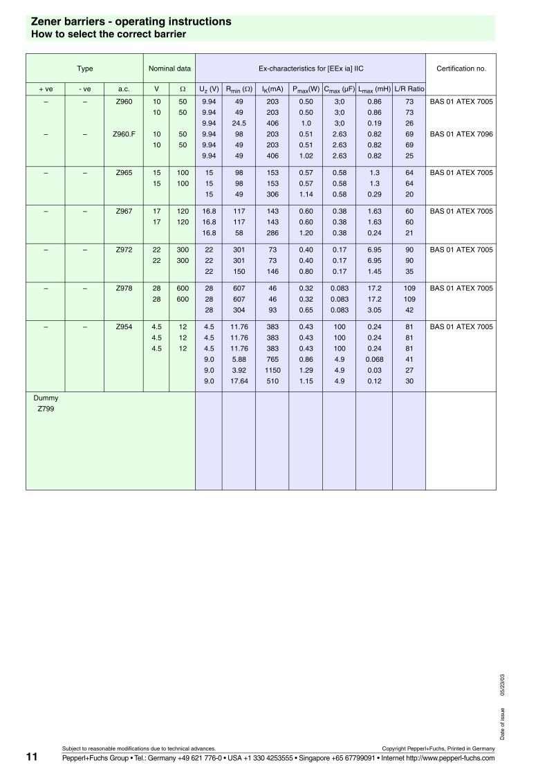
Type Nominal data Ex-characteristics for [EEx ia] IIC Certification no.
+ ve - ve a.c. V � Uz (V) Rmin (�) IK(mA) Pmax(W) Cmax (µF) Lmax (mH) L/R Ratio
–
–
–
–
Z960
Z960.F
10
10
10
10
50
50
50
50
9.94
9.94
9.94
9.94
9.94
9.94
49
49
24.5
98
49
49
203
203
406
203
203
406
0.50
0.50
1.0
0.51
0.51
1.02
3;0
3;0
3;0
2.63
2.63
2.63
0.86
0.86
0.19
0.82
0.82
0.82
73
73
26
69
69
25
BAS 01 ATEX 7005
BAS 01 ATEX 7096
– – Z965 15
15
100
100
15
15
15
98
98
49
153
153
306
0.57
0.57
1.14
0.58
0.58
0.58
1.3
1.3
0.29
64
64
20
BAS 01 ATEX 7005
– – Z967 17
17
120
120
16.8
16.8
16.8
117
117
58
143
143
286
0.60
0.60
1.20
0.38
0.38
0.38
1.63
1.63
0.24
60
60
21
BAS 01 ATEX 7005
– – Z972 22
22
300
300
22
22
22
301
301
150
73
73
146
0.40
0.40
0.80
0.17
0.17
0.17
6.95
6.95
1.45
90
90
35
BAS 01 ATEX 7005
– – Z978 28
28
600
600
28
28
28
607
607
304
46
46
93
0.32
0.32
0.65
0.083
0.083
0.083
17.2
17.2
3.05
109
109
42
BAS 01 ATEX 7005
– – Z954 4.5
4.5
4.5
12
12
12
4.5
4.5
4.5
9.0
9.0
9.0
11.76
11.76
11.76
5.88
3.92
17.64
383
383
383
765
1150
510
0.43
0.43
0.43
0.86
1.29
1.15
100
100
100
4.9
4.9
4.9
0.24
0.24
0.24
0.068
0.03
0.12
81
81
81
41
27
30
BAS 01 ATEX 7005
Dummy
Z799
12
Zener barriers - operating instructionsHow to select the correct barrier
Subject to reasonable modifications due to technical advances. Copyright Pepperl+Fuchs, Printed in Germany
Pepperl+Fuchs Group • Tel.: Germany +49 621 776-0 • USA +1 330 4253555 • Singapore +65 67799091 • Internet http://www.pepperl-fuchs.com
Dat
e of
issu
e05
/23/
03
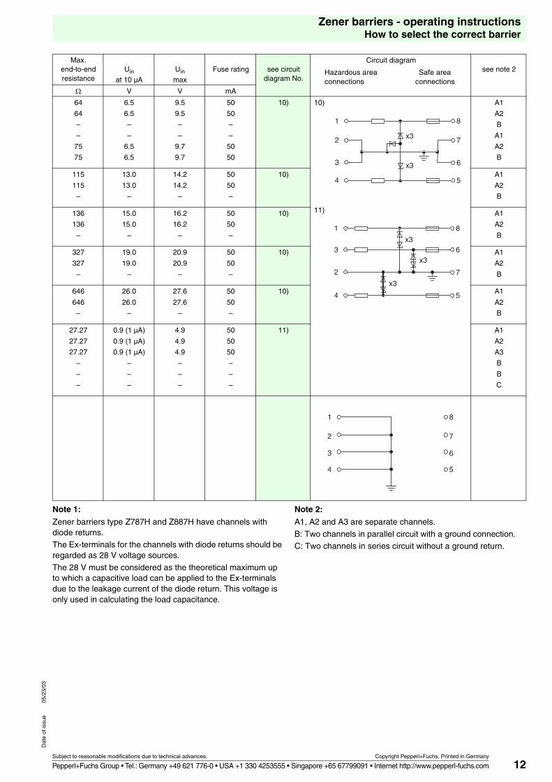
Note 1:
Zener barriers type Z787H and Z887H have channels with diode returns.The Ex-terminals for the channels with diode returns should be regarded as 28 V voltage sources.
The 28 V must be considered as the theoretical maximum up to which a capacitive load can be applied to the Ex-terminals due to the leakage current of the diode return. This voltage is only used in calculating the load capacitance.
Note 2:
A1, A2 and A3 are separate channels.
B: Two channels in parallel circuit with a ground connection.C: Two channels in series circuit without a ground return.
Max.end-to-end resistance
Uin
at 10 µA
Uin
max
Fuse rating see circuitdiagram No.
Circuit diagram
Hazardous area Safe areaconnections connections
see note 2
� V V mA
64
64
–
–
75
75
6.5
6.5
–
–
6.5
6.5
9.5
9.5
–
–
9.7
9.7
50
50
–
–
50
50
10) 10)
11)
A1
A2
B
A1
A2
B
115
115
–
13.0
13.0
–
14.2
14.2
–
50
50
–
10) A1
A2
B
136
136
–
15.0
15.0
–
16.2
16.2
–
50
50
–
10) A1
A2
B
327
327
–
19.0
19.0
–
20.9
20.9
–
50
50
–
10) A1
A2
B
646
646
–
26.0
26.0
–
27.6
27.6
–
50
50
–
10) A1
A2
B
27.27
27.27
27.27
–
–
–
0.9 (1 µA)
0.9 (1 µA)
0.9 (1 µA)
–
–
–
4.9
4.9
4.9
–
–
–
50
50
50
–
–
–
11) A1
A2
A3
B
B
C
1 8
4 5
2 7
3 6x3
x3
1 8
4 5
3 6
2 7
x3
x3
x3
1 8
4 5
2 7
3 6
13
Zener barriers - operating instructionsApplication examples
Subject to reasonable modifications due to technical advances. Copyright Pepperl+Fuchs, Printed in Germany
Pepperl+Fuchs Group • Tel.: Germany +49 621 776-0 • USA +1 330 4253555 • Singapore +65 67799091 • Internet http://www.pepperl-fuchs.com
Dat
e of
issu
e05
/23/
03
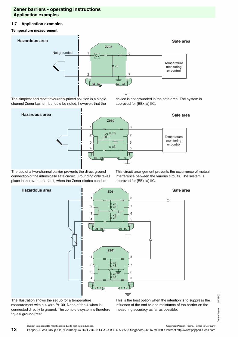
1.7 Application examples
Temperature measurement
The simplest and most favourably priced solution is a single-channel Zener barrier. It should be noted, however, that the
device is not grounded in the safe area. The system is approved for [EEx ia] IIC.
The use of a two-channel barrier prevents the direct ground connection of the intrinsically safe circuit. Grounding only takes place in the event of a fault, when the Zener diodes conduct.
This circuit arrangement prevents the occurrence of mutual interference between the various circuits. The system is approved for [EEx ia] IIC.
The illustration shows the set up for a temperature measurement with a 4-wire Pt100. None of the 4 wires is connected directly to ground. The complete system is therefore "quasi ground-free".
This is the best option when the intention is to suppress the influence of the end-to-end resistance of the barrier on the measuring accuracy as far as possible.
Temperaturemonitoringor control
Hazardous area Safe area
Not grounded
Z705
x3
CL1
2
8
7
Temperaturemonitoringor control
Hazardous area Safe areaZ960
x3x3
x3
1
2
3
4
8
7
6
5
Hazardous area Safe area
V
Z961
x3x3
x3x3
1
2
3
4
8
7
6
5
Z961
x3x3
x3x3
1
2
3
4
8
7
6
5
14
Zener barriers - operating instructionsApplication examples
Subject to reasonable modifications due to technical advances. Copyright Pepperl+Fuchs, Printed in Germany
Pepperl+Fuchs Group • Tel.: Germany +49 621 776-0 • USA +1 330 4253555 • Singapore +65 67799091 • Internet http://www.pepperl-fuchs.com
Dat
e of
issu
e05
/23/
03
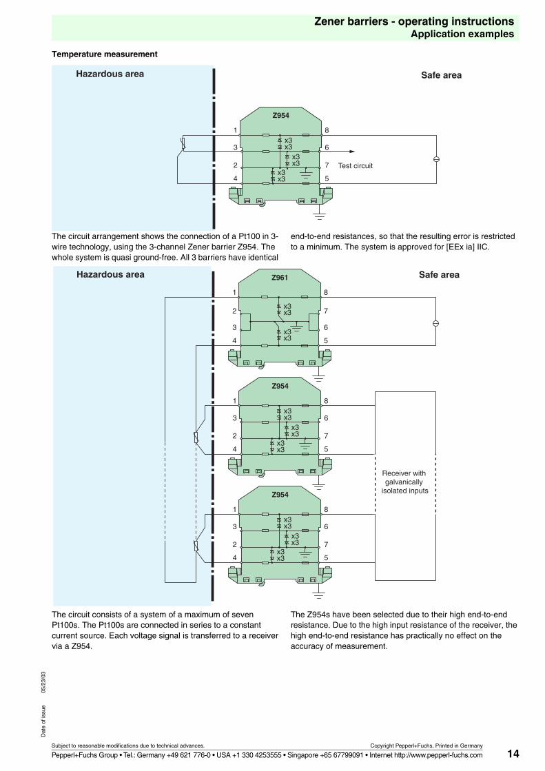
Temperature measurement
The circuit arrangement shows the connection of a Pt100 in 3-wire technology, using the 3-channel Zener barrier Z954. The whole system is quasi ground-free. All 3 barriers have identical
end-to-end resistances, so that the resulting error is restricted to a minimum. The system is approved for [EEx ia] IIC.
The circuit consists of a system of a maximum of seven Pt100s. The Pt100s are connected in series to a constant current source. Each voltage signal is transferred to a receiver via a Z954.
The Z954s have been selected due to their high end-to-end resistance. Due to the high input resistance of the receiver, the high end-to-end resistance has practically no effect on the accuracy of measurement.
Hazardous area Safe area
Test circuit
1
3
2
4
Z954
x3x3
x3x3
x3x3
8
6
7
5
Hazardous area Safe area
Receiver with galvanically
isolated inputs
Z961
x3x3
x3x3
1
2
3
4
8
7
6
5
Z954
x3x3
x3x3
x3x3
1
3
2
4
8
6
7
5
1
3
2
4
8
6
7
Z954
x3x3
x3x3
x3x3 5
15
Zener barriers - operating instructionsApplication examples
Subject to reasonable modifications due to technical advances. Copyright Pepperl+Fuchs, Printed in Germany
Pepperl+Fuchs Group • Tel.: Germany +49 621 776-0 • USA +1 330 4253555 • Singapore +65 67799091 • Internet http://www.pepperl-fuchs.com
Dat
e of
issu
e05
/23/
03
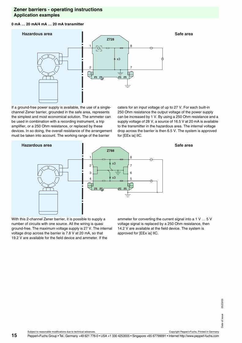
0 mA … 20 mA/4 mA … 20 mA transmitter
If a ground-free power supply is available, the use of a single-channel Zener barrier, grounded in the safe area, represents the simplest and most economical solution. The ammeter can be used in combination with a recording instrument, a trip amplifier, or a 250 Ohm resistance, or replaced by these devices. In so doing, the overall resistance of the arrangement must be taken into account. The working range of the barrier
caters for an input voltage of up to 27 V. For each built-in 250 Ohm resistance the output voltage of the power supply can be increased by 1 V. By using a 250 Ohm resistance and a supply voltage of 28 V, a source of 16.5 V at 20 mA is available to the transmitter in the hazardous area. The internal voltage drop across the barrier is then 6.5 V. The system is approved for [EEx ia] IIC.
With this 2-channel Zener barrier, it is possible to supply a number of circuits with one source. All the wiring is quasi ground-free. The maximum voltage supply is 27 V. The internal voltage drop across the barrier is 7.8 V at 20 mA, so that 19.2 V are available for the field device and ammeter. If the
ammeter for converting the current signal into a 1 V … 5 V voltage signal is replaced by a 250 Ohm resistance, then 14.2 V are available at the field device. The system is approved for [EEx ia] IIC.
Hazardous area Safe area
A
Z728
x3
CL1
2
8
7
Hazardous area Safe areaZ788
x3
x3
1
2
3
4
8
7
6
5A
16
Zener barriers - operating instructionsApplication examples
Subject to reasonable modifications due to technical advances. Copyright Pepperl+Fuchs, Printed in Germany
Pepperl+Fuchs Group • Tel.: Germany +49 621 776-0 • USA +1 330 4253555 • Singapore +65 67799091 • Internet http://www.pepperl-fuchs.com
Dat
e of
issu
e05
/23/
03
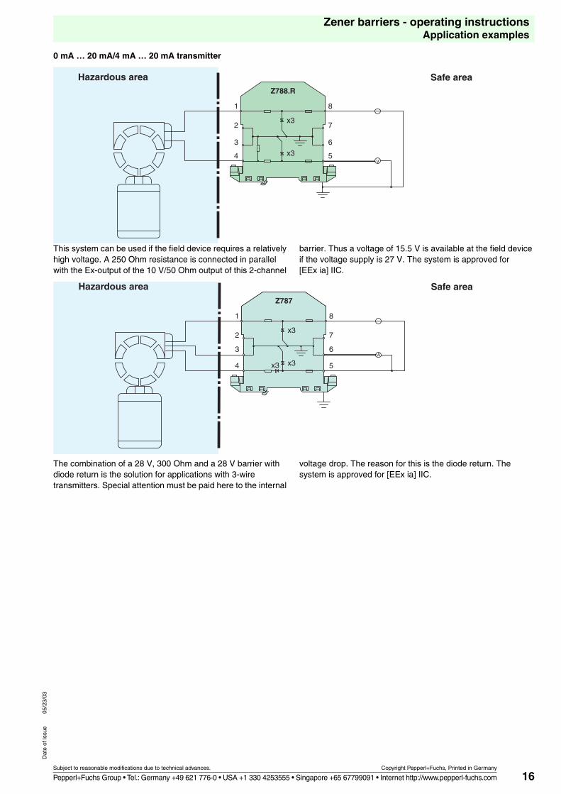
0 mA … 20 mA/4 mA … 20 mA transmitter
This system can be used if the field device requires a relatively high voltage. A 250 Ohm resistance is connected in parallel with the Ex-output of the 10 V/50 Ohm output of this 2-channel
barrier. Thus a voltage of 15.5 V is available at the field device if the voltage supply is 27 V. The system is approved for [EEx ia] IIC.
The combination of a 28 V, 300 Ohm and a 28 V barrier with diode return is the solution for applications with 3-wire transmitters. Special attention must be paid here to the internal
voltage drop. The reason for this is the diode return. The system is approved for [EEx ia] IIC.
Hazardous area Safe areaZ788.R
x3
x3
1
2
3
4
8
7
6
5V
Hazardous area Safe areaZ787
x3
x3x3
1
2
3
4
8
7
6
5
A
17
Zener barriers - operating instructionsApplication examples
Subject to reasonable modifications due to technical advances. Copyright Pepperl+Fuchs, Printed in Germany
Pepperl+Fuchs Group • Tel.: Germany +49 621 776-0 • USA +1 330 4253555 • Singapore +65 67799091 • Internet http://www.pepperl-fuchs.com
Dat
e of
issu
e05
/23/
03
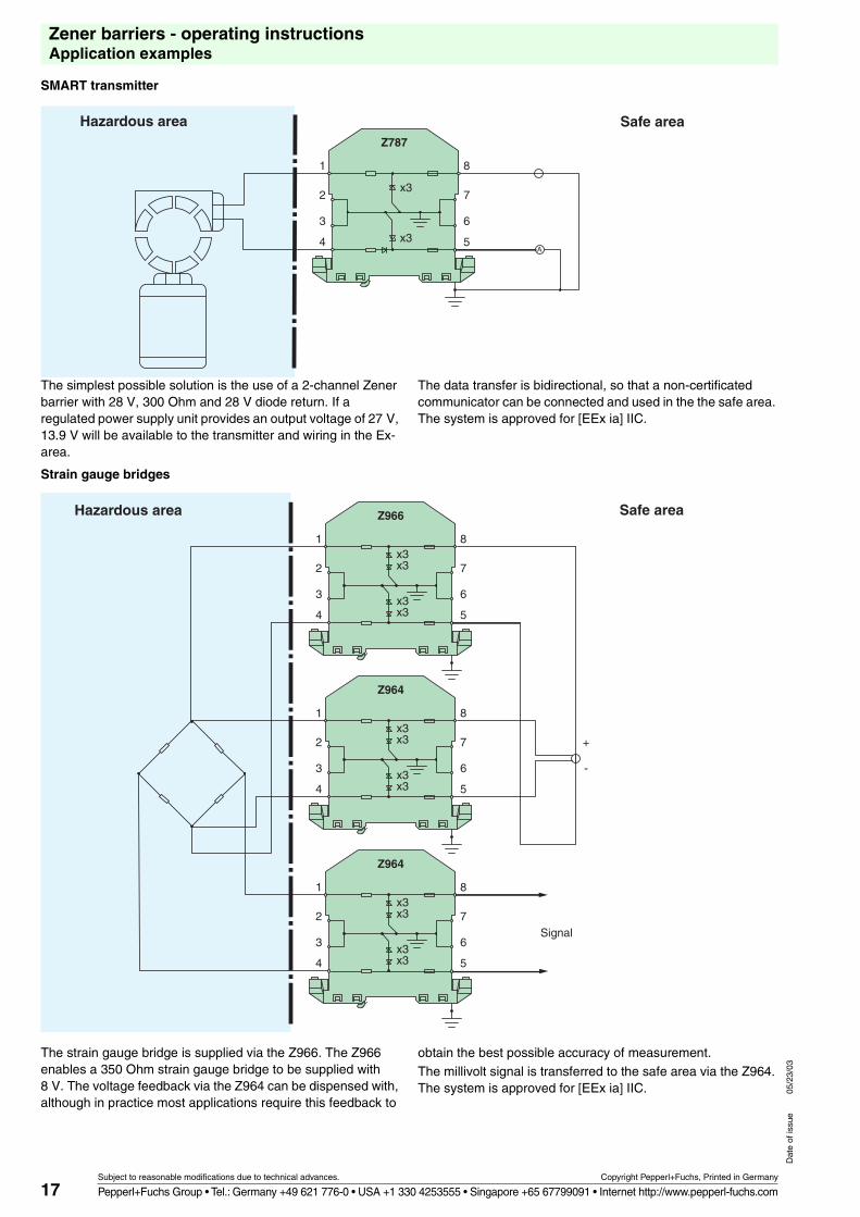
SMART transmitter
The simplest possible solution is the use of a 2-channel Zener barrier with 28 V, 300 Ohm and 28 V diode return. If a regulated power supply unit provides an output voltage of 27 V, 13.9 V will be available to the transmitter and wiring in the Ex-area.
The data transfer is bidirectional, so that a non-certificated communicator can be connected and used in the the safe area. The system is approved for [EEx ia] IIC.
Strain gauge bridges
The strain gauge bridge is supplied via the Z966. The Z966 enables a 350 Ohm strain gauge bridge to be supplied with 8 V. The voltage feedback via the Z964 can be dispensed with, although in practice most applications require this feedback to
obtain the best possible accuracy of measurement.The millivolt signal is transferred to the safe area via the Z964. The system is approved for [EEx ia] IIC.
Hazardous area Safe areaZ787
A
8
7
6
5
1
2
3
4
x3
x3
Hazardous area Safe area
Signal
Z966
x3x3
x3x3
1
2
3
4
8
7
6
5
Z964
x3x3
x3x3
1
2
3
4
8
7
6
+
-
5
Z964
x3x3
x3x3
1
2
3
4
8
7
6
5
18
Zener barriers - operating instructionsApplication examples
Subject to reasonable modifications due to technical advances. Copyright Pepperl+Fuchs, Printed in Germany
Pepperl+Fuchs Group • Tel.: Germany +49 621 776-0 • USA +1 330 4253555 • Singapore +65 67799091 • Internet http://www.pepperl-fuchs.com
Dat
e of
issu
e05
/23/
03
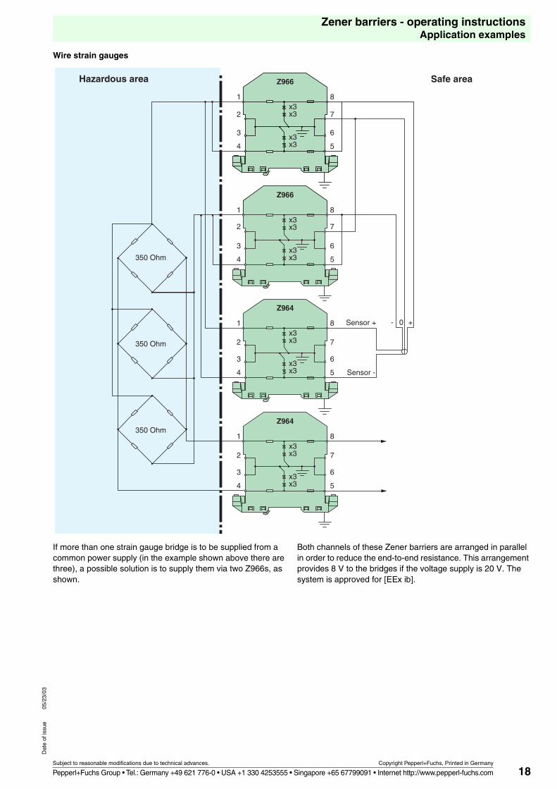
Wire strain gauges
If more than one strain gauge bridge is to be supplied from a common power supply (in the example shown above there are three), a possible solution is to supply them via two Z966s, as shown.
Both channels of these Zener barriers are arranged in parallel in order to reduce the end-to-end resistance. This arrangement provides 8 V to the bridges if the voltage supply is 20 V. The system is approved for [EEx ib].
Hazardous area Safe area
Sensor +
Sensor -
350 Ohm
350 Ohm
350 Ohm
1
2
3
4
Z966
x3x3
x3
8
6x3
7
5
Z966
1
2
3
4
8
6
x3
x3
7
5
x3
x3
Z964
x3
x3
x3
x3
1
2
3
4
8
7
6
5
Z964
x3x3
x3x3
1
2
3
4
8
7
6
5
- 0 +
19
Zener barriers - operating instructionsApplication examples
Subject to reasonable modifications due to technical advances. Copyright Pepperl+Fuchs, Printed in Germany
Pepperl+Fuchs Group • Tel.: Germany +49 621 776-0 • USA +1 330 4253555 • Singapore +65 67799091 • Internet http://www.pepperl-fuchs.com
Dat
e of
issu
e05
/23/
03
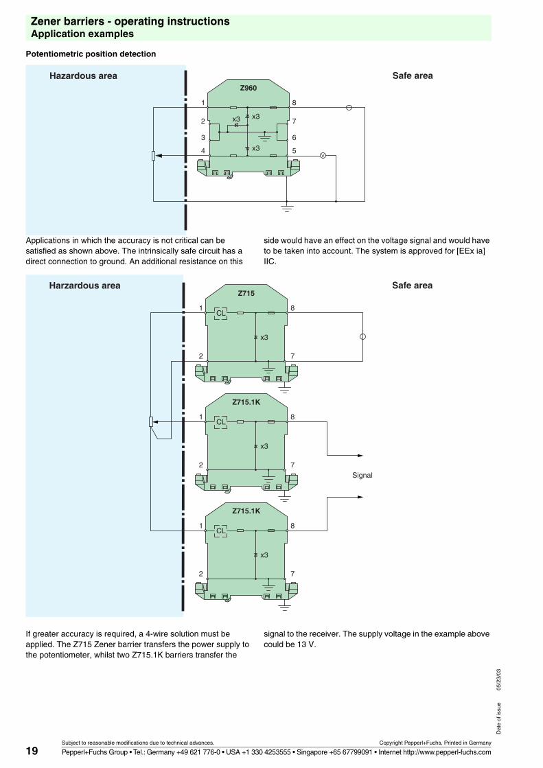
Potentiometric position detection
Applications in which the accuracy is not critical can be satisfied as shown above. The intrinsically safe circuit has a direct connection to ground. An additional resistance on this
side would have an effect on the voltage signal and would have to be taken into account. The system is approved for [EEx ia] IIC.
If greater accuracy is required, a 4-wire solution must be applied. The Z715 Zener barrier transfers the power supply to the potentiometer, whilst two Z715.1K barriers transfer the
signal to the receiver. The supply voltage in the example above could be 13 V.
Hazardous area Safe area
V
Z960
x3x3
x3
1
2
3
4
8
7
6
5
Harzardous area Safe area
Signal
Z715
x3
CL1
2
8
7
Z715.1K
x3
CL1
2
8
7
Z715.1K
x3
CL1
2
8
7
20
Zener barriers - operating instructionsApplication examples
Subject to reasonable modifications due to technical advances. Copyright Pepperl+Fuchs, Printed in Germany
Pepperl+Fuchs Group • Tel.: Germany +49 621 776-0 • USA +1 330 4253555 • Singapore +65 67799091 • Internet http://www.pepperl-fuchs.com
Dat
e of
issu
e05
/23/
03
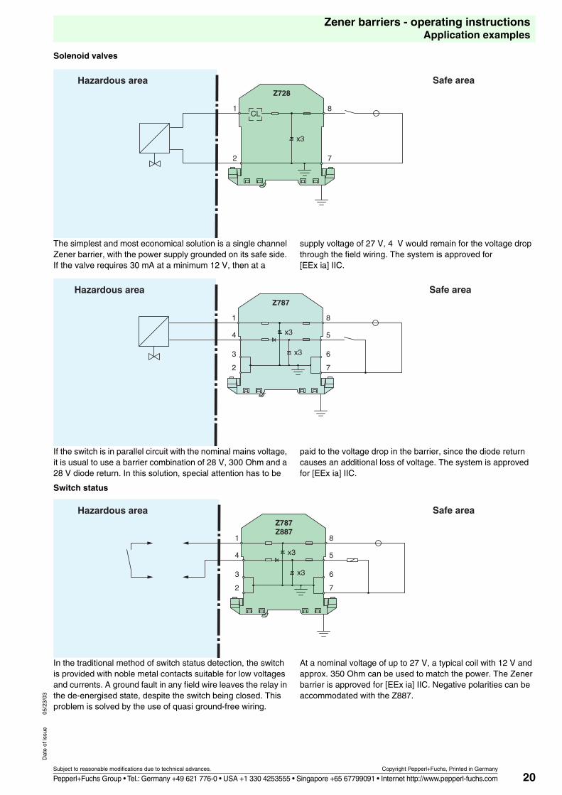
Solenoid valves
The simplest and most economical solution is a single channel Zener barrier, with the power supply grounded on its safe side. If the valve requires 30 mA at a minimum 12 V, then at a
supply voltage of 27 V, 4 V would remain for the voltage drop through the field wiring. The system is approved for [EEx ia] IIC.
If the switch is in parallel circuit with the nominal mains voltage, it is usual to use a barrier combination of 28 V, 300 Ohm and a 28 V diode return. In this solution, special attention has to be
paid to the voltage drop in the barrier, since the diode return causes an additional loss of voltage. The system is approved for [EEx ia] IIC.
Switch status
In the traditional method of switch status detection, the switch is provided with noble metal contacts suitable for low voltages and currents. A ground fault in any field wire leaves the relay in the de-energised state, despite the switch being closed. This problem is solved by the use of quasi ground-free wiring.
At a nominal voltage of up to 27 V, a typical coil with 12 V and approx. 350 Ohm can be used to match the power. The Zener barrier is approved for [EEx ia] IIC. Negative polarities can be accommodated with the Z887.
Hazardous area Safe areaZ728
x3
CL1
2
8
7
Hazardous area Safe areaZ787
x3
x3
1
4
3
2
8
5
6
7
Hazardous area Safe areaZ787Z887
x3
x3
1
4
3
2
8
5
6
7
21
Zener barriers - operating instructionsApplication examples
Subject to reasonable modifications due to technical advances. Copyright Pepperl+Fuchs, Printed in Germany
Pepperl+Fuchs Group • Tel.: Germany +49 621 776-0 • USA +1 330 4253555 • Singapore +65 67799091 • Internet http://www.pepperl-fuchs.com
Dat
e of
issu
e05
/23/
03
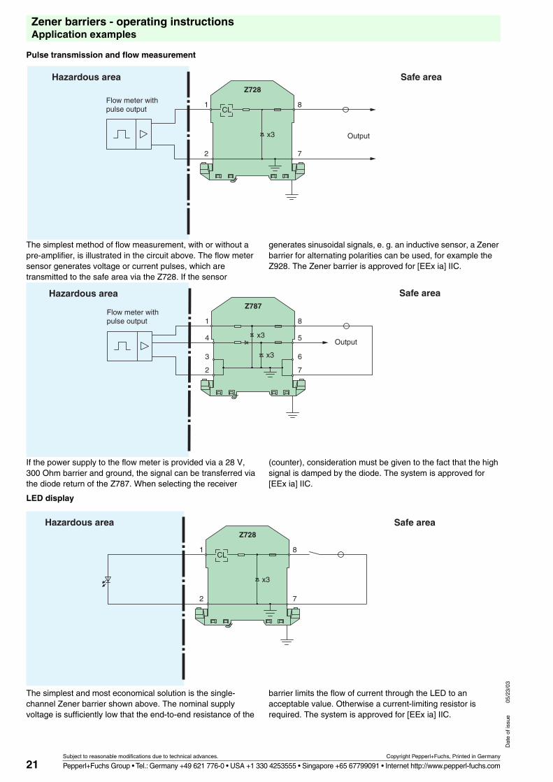
Pulse transmission and flow measurement
The simplest method of flow measurement, with or without a pre-amplifier, is illustrated in the circuit above. The flow meter sensor generates voltage or current pulses, which are transmitted to the safe area via the Z728. If the sensor
generates sinusoidal signals, e. g. an inductive sensor, a Zener barrier for alternating polarities can be used, for example the Z928. The Zener barrier is approved for [EEx ia] IIC.
If the power supply to the flow meter is provided via a 28 V, 300 Ohm barrier and ground, the signal can be transferred via the diode return of the Z787. When selecting the receiver
(counter), consideration must be given to the fact that the high signal is damped by the diode. The system is approved for [EEx ia] IIC.
LED display
The simplest and most economical solution is the single-channel Zener barrier shown above. The nominal supply voltage is sufficiently low that the end-to-end resistance of the
barrier limits the flow of current through the LED to an acceptable value. Otherwise a current-limiting resistor is required. The system is approved for [EEx ia] IIC.
Hazardous area Safe area
Output
Flow meter withpulse output
Z728
x3
CL1
2
8
7
Hazardous area Safe area
Output
Flow meter withpulse output 1
4
3
2
8
5
6
7
Z787
x3
x3
Hazardous area Safe areaZ728
x3
CL1
2
8
7
22
Zener barriers - operating instructionsApplication examples
Subject to reasonable modifications due to technical advances. Copyright Pepperl+Fuchs, Printed in Germany
Pepperl+Fuchs Group • Tel.: Germany +49 621 776-0 • USA +1 330 4253555 • Singapore +65 67799091 • Internet http://www.pepperl-fuchs.com
Dat
e of
issu
e05
/23/
03
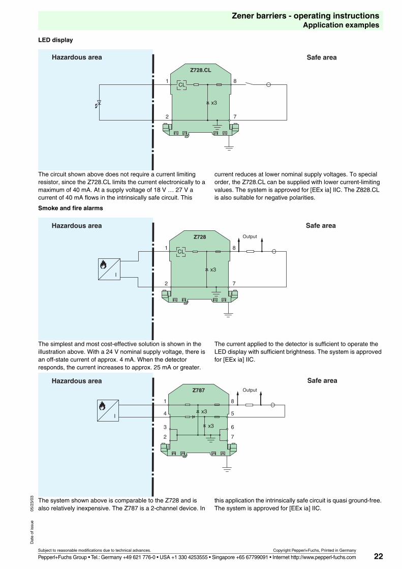
LED display
The circuit shown above does not require a current limiting resistor, since the Z728.CL limits the current electronically to a maximum of 40 mA. At a supply voltage of 18 V … 27 V a current of 40 mA flows in the intrinsically safe circuit. This
current reduces at lower nominal supply voltages. To special order, the Z728.CL can be supplied with lower current-limiting values. The system is approved for [EEx ia] IIC. The Z828.CL is also suitable for negative polarities.
Smoke and fire alarms
The simplest and most cost-effective solution is shown in the illustration above. With a 24 V nominal supply voltage, there is an off-state current of approx. 4 mA. When the detector responds, the current increases to approx. 25 mA or greater.
The current applied to the detector is sufficient to operate the LED display with sufficient brightness. The system is approved for [EEx ia] IIC.
The system shown above is comparable to the Z728 and is also relatively inexpensive. The Z787 is a 2-channel device. In
this application the intrinsically safe circuit is quasi ground-free. The system is approved for [EEx ia] IIC.
Hazardous area Safe area
Z728.CL
x3
1
2
8
7
CL
Hazardous area Safe area
Output
I
Z728
x3
CL1
2
8
7
Hazardous area Safe areaOutput
I
Z787
x3
x3
1
4
3
2
8
5
6
7
23
Zener barriers - operating instructionsApplication examples
Subject to reasonable modifications due to technical advances. Copyright Pepperl+Fuchs, Printed in Germany
Pepperl+Fuchs Group • Tel.: Germany +49 621 776-0 • USA +1 330 4253555 • Singapore +65 67799091 • Internet http://www.pepperl-fuchs.com
Dat
e of
issu
e05
/23/
03
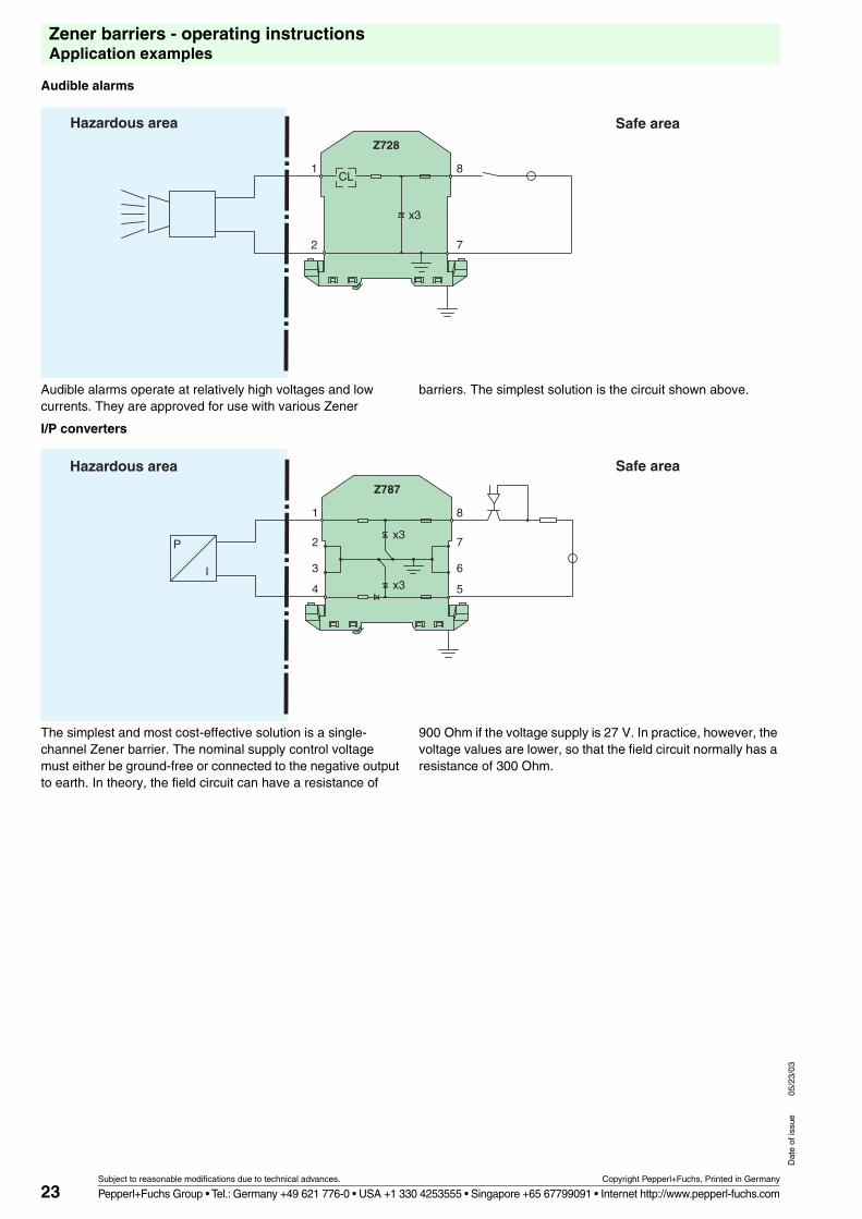
Audible alarms
Audible alarms operate at relatively high voltages and low currents. They are approved for use with various Zener
barriers. The simplest solution is the circuit shown above.
I/P converters
The simplest and most cost-effective solution is a single-channel Zener barrier. The nominal supply control voltage must either be ground-free or connected to the negative output to earth. In theory, the field circuit can have a resistance of
900 Ohm if the voltage supply is 27 V. In practice, however, the voltage values are lower, so that the field circuit normally has a resistance of 300 Ohm.
Hazardous area Safe areaZ728
x3
CL1
2
8
7
Hazardous area Safe area
P
I
1
2
3
4
Z787
x3
x3
8
7
6
5