Embed Size (px)
Citation preview

1
US/Japan Workshop on Power Plant Studies and Related Advanced Technologies5-7 March 2008, UCSD
Feasibility Study on the Fast-Ignition Laser Fusion Reactor With a Dry Wall
FALCON-D*
Yuichi OGAWA, Takuya GOTOThe University of Tokyo
Kunihiko OKANO, Ryoji HIWATARI and Yoshiyuki ASAOKACentral Research Institute of Electric Power Industry
Youji SOMEYAMusashi Institute of Technology
1. Rationale 2. Core plasma analysis 3. Dry wall chamber design4. Maintenance scenario5. Summary
*) Fast-ignition Advanced Laser reactor CONcept – Dry wall version -

2
Fast Ignition vs Central Ignition
Fast ignition
Central ignition
Laser Energy (MJ)
Gain
A fuel volume in the fast ignition pellet is 1/5~1/10 times as small as that in the central one.A fusion yield in one shot is remarkably reduced in the fast ignition. A new reactor concept so as to make full use of this advantage
Central ignition Fast ignition Isobaric isochoric
3
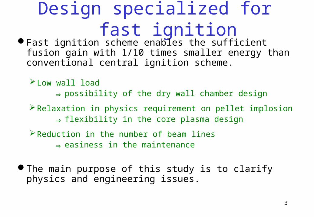
Design specialized for fast ignitionFast ignition scheme enables the sufficient fusion gain with 1/10
times smaller energy than conventional central ignition scheme.
Low wall load ⇒ possibility of the dry wall chamber design
Relaxation in physics requirement on pellet implosion ⇒ flexibility in the core plasma design
Reduction in the number of beam lines ⇒ easiness in the maintenance
The main purpose of this study is to clarify physics and engineering issues.

4
Comparison with other designsFALCON-D
Osaka Univ.
KOYO
Osaka Univ.
KOYO-Fast
US
HAPL
chamber radius[m] 5.64 4 3 11
heating methodfast
Ignition
central ignition
fast
ignition
central ignition
chamber wall Solid liquid liquid solid*1
input energy Ein[MJ]
(implosion / heating)
0.4
(0.35/0.05)
3.4 1.2
(1.13/0.07)
2.36 *2
pellet gain G 100 176 167 148
target yield Efus[MJ] 40 600 200 350
pulse load (except neutron) [J/cm2]
2.0 60 35 4.6
repetition rate frep[Hz] 30 12(3×4) 16(4×4) 5
plant fusion power Pfus[MW] 1200 7200 3200 1750
*1 considering magnetic intervention scheme*2 assumed value from the pellet gain

5
Repetition Rate of Laser Pulse
Repetition rate is limited byLaser engineering technology
16Hz laser system is considered in the KOYO-Fast reactor designTechnically >50Hz is achievable
Chamber vacuum pumpingPumping capacity of ~50Pa ・ m3/s enables 30Hz repetitionAdequate design of pumping port can cover this requirement
Pellet injectionMultiple injector should be introducedPellet injection speed ~500m/s, and 50 Hz requires a chamber size <
~10m
30Hz repetition is acceptable and achievable
6
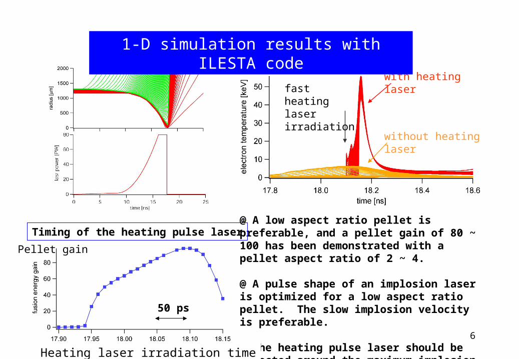
fast heating laser irradiation
with heating laser
without heating laser
@ A low aspect ratio pellet is preferable, and a pellet gain of 80 ~ 100 has been demonstrated with a pellet aspect ratio of 2 ~ 4.
@ A pulse shape of an implosion laser is optimized for a low aspect ratio pellet. The slow implosion velocity is preferable.
@ The heating pulse laser should be injected around the maximum implosion phase within a time interval of a few tens picoseconds.
1-D simulation results with ILESTA code
Heating laser irradiation time
Pellet gain
50 ps
Timing of the heating pulse laser
7
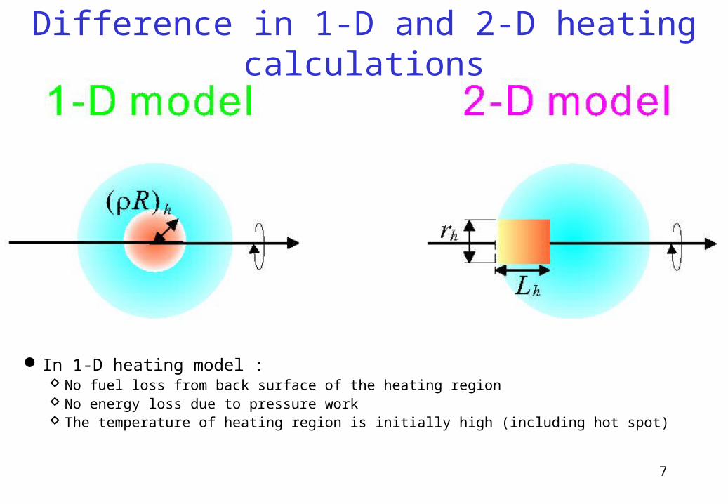
Difference in 1-D and 2-D heating calculations
In 1-D heating model : No fuel loss from back surface of the heating region No energy loss due to pressure work The temperature of heating region is initially high (including hot spot)
8
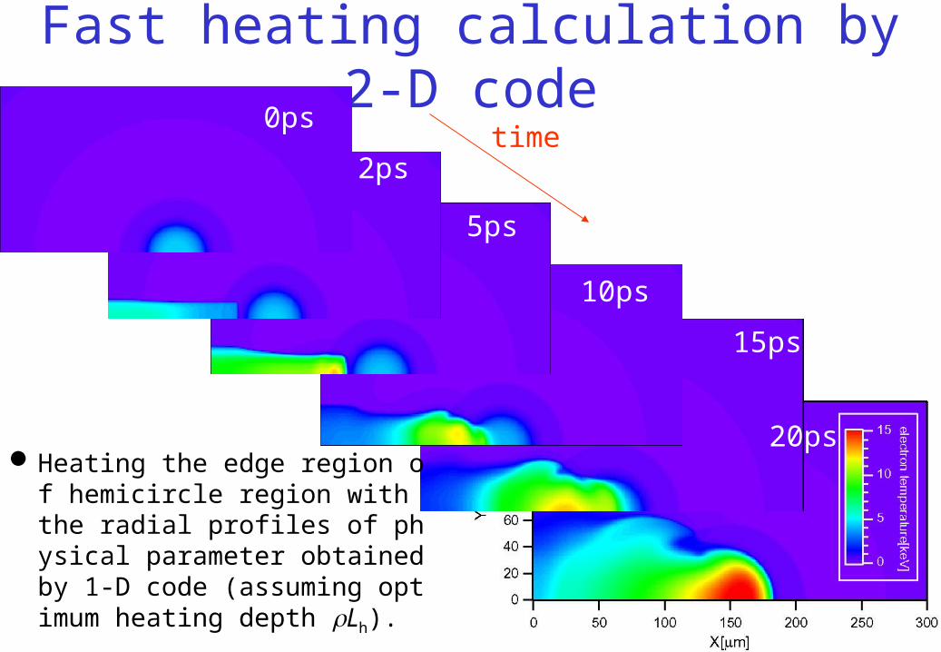
Fast heating calculation by 2-D codetime
2ps
0ps
5ps
10ps
15ps
20psHeating the edge region of hemi
circle region with the radial profiles of physical parameter obtained by 1-D code (assuming optimum heating depth Lh).
9
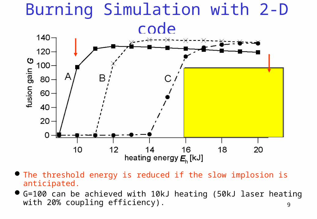
Burning Simulation with 2-D code
The threshold energy is reduced if the slow implosion is anticipated. G=100 can be achieved with 10kJ heating (50kJ laser heating with
20% coupling efficiency).
10
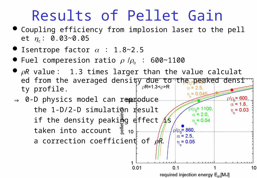
Results of Pellet Gain Coupling efficiency from implosion laser to the pellet c : 0.03~0.05
Isentrope factor : 1.8~2.5 Fuel comperesion ratio : 600~1100
R value : 1.3 times larger than the value calculated from the averaged density due to the peaked density profile.
⇒ 0-D physics model can reproduce
the 1-D/2-D simulation result
if the density peaking effect is
taken into account
a correction coefficient of R.

11
Thermal response of the material to the heat load is calculated by 1-D thermal conduction equation with temperature-dependent material properties.
The energy deposition profile is calculated from photoabsorption coefficient and ion stopping of the material.
Assuming chamber radius of 5.64m and 30Hz repetition.
Design of the solid first wall
X-rays and charged particles
analyzed region (4mm)
coolant(supercritical water, 623K)
adiabatic boundary
W(1mm)
F82H(3mm)
convection cooling
12
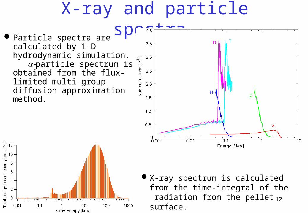
X-ray and particle spectra Particle spectra are calculated
by 1-D hydrodynamic simulation. particle spectrum is obtained from the flux-limited multi-group diffusion approximation method.
X-ray spectrum is calculated from the time-integral of the radiation from the pellet surface.
13
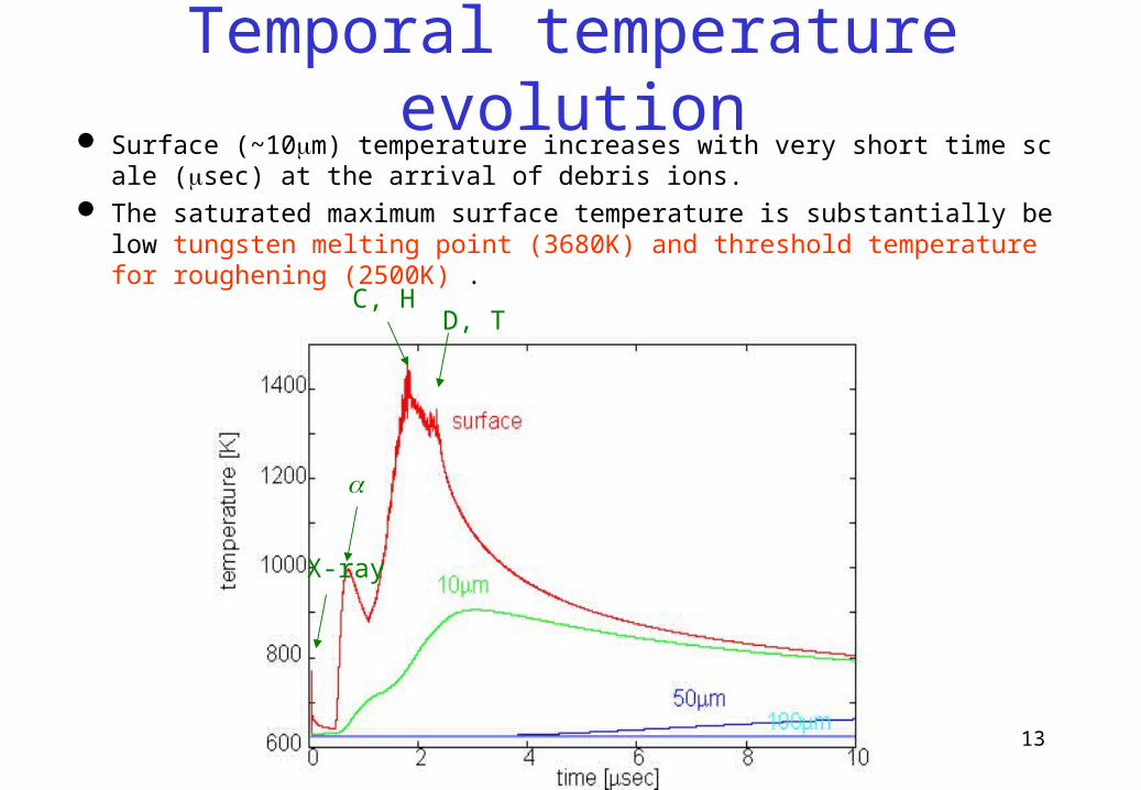
Surface (~10m) temperature increases with very short time scale (sec) at the arrival of debris ions.
The saturated maximum surface temperature is substantially below tungsten melting point (3680K) and threshold temperature for roughening (2500K) .
Temporal temperature evolution
X-ray
C, HD, T

14
Calculations were held by ANSYS® code.
A simple bilinear approximation was used to describe stress-strain behavior in a plastic deformation. No dynamic effect was considered. Temperature dependence of yield stress were included.
Thermomechanical analysis model
adiabatic boundary
W(1mm)
FS(3mm)
convection cooling
Axisymmetric boundary coupled
displacement
z
*T. Dümmer et al., Acta. mater. 46 (1998) 6267-6290.

15
The surface strain is correlated with the temperature. The plastic strain at the maximum temperature reaches 0.01 (compression).
The surface stress during plastic deformation coincides to the yield stress determined by the temperature at the time.
The region close to the surface undergoes plastic deformation not only in heating phase but also in cooling phase.
The deeper region (>20m) only undergoes elastic deformation.
Thermal stress
heating, plastic
cooling, plastic
cooling, elastic
heating, elastic
16
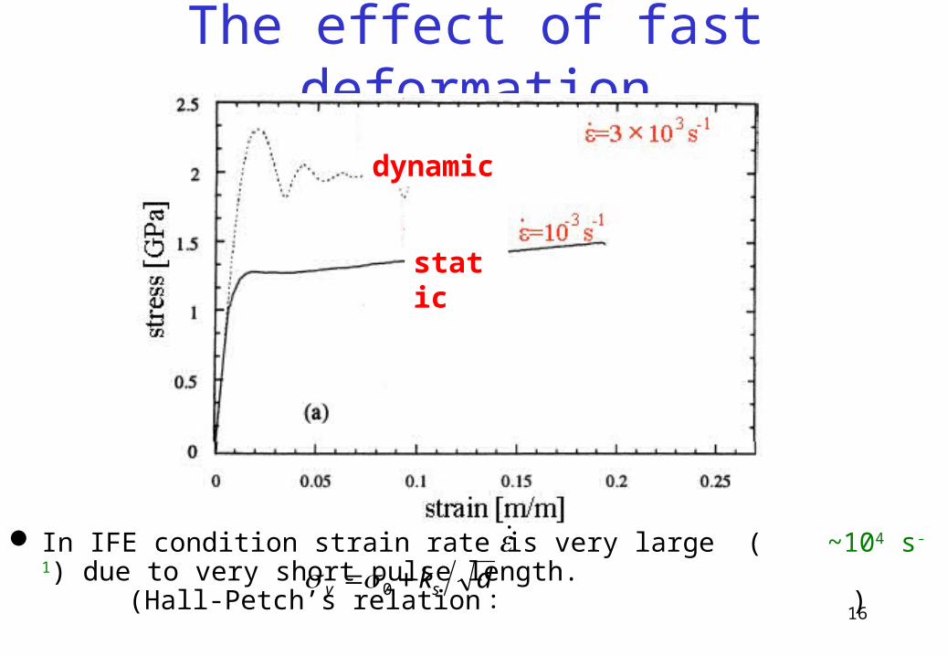
In IFE condition strain rate is very large ( ~104 s-1) due to very short pulse length. (Hall-Petch’s relation : )
The effect of fast deformation
dksy 0
static
dynamic

17
The research in Tohoku University provided ultra fine-grained material that has grain size of several tens nanometers by molding a metal powder with a small amount of additives through mechanical alloying (MA) process (normally grain size is 1-10m).
In case of molybdenum, the thermomechanical properties in high temperature region or after irradiation are substantially improved.
Ultra fine-grained mateiral
*H. Kurishita et al., J. Nucl. Mater. 367-370 (2007) 1453-1457.
In case of tungsten, ultra fine-grained tungsten (UFG-W) has been developed by MA with TiC powder under the atmosphere of hydrogen or argon*.
UFG-W
as-received W
18
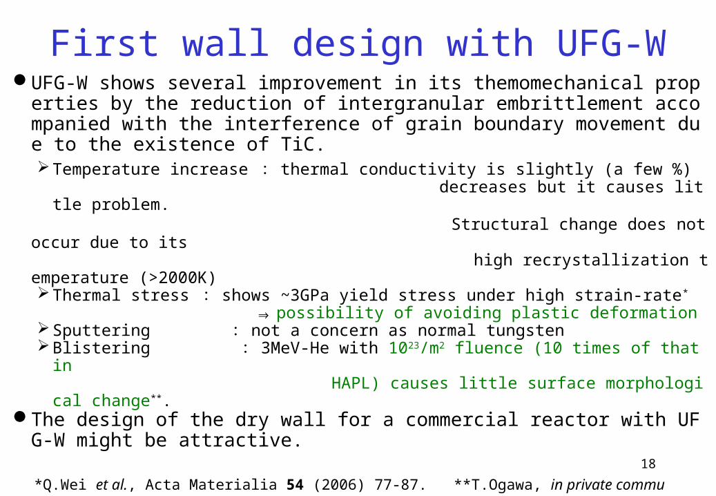
UFG-W shows several improvement in its themomechanical properties by the reduction of intergranular embrittlement accompanied with the interference of grain boundary movement due to the existence of TiC.Temperature increase : thermal conductivity is slightly (a few %) decreases but it causes little problem.
Structural change does not occur due to its high recrystallization temperature (>2000K)
Thermal stress : shows ~3GPa yield stress under high strain-rate*
⇒ possibility of avoiding plastic deformationSputtering : not a concern as normal tungstenBlistering : 3MeV-He with 1023/m2 fluence (10 times of that in HAPL) causes little surface morphological change**.
The design of the dry wall for a commercial reactor with UFG-W might be attractive.
First wall design with UFG-W
*Q.Wei et al., Acta Materialia 54 (2006) 77-87. **T.Ogawa, in private communication.
19
20
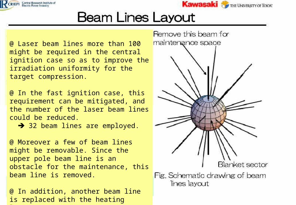
@ Laser beam lines more than 100 might be required in the central ignition case so as to improve the irradiation uniformity for the target compression.
@ In the fast ignition case, this requirement can be mitigated, and the number of the laser beam lines could be reduced. 32 beam lines are employed.
@ Moreover a few of beam lines might be removable. Since the upper pole beam line is an obstacle for the maintenance, this beam line is removed.
@ In addition, another beam line is replaced with the heating laser. Eventually, 30 beam lines for compression laser
21
22
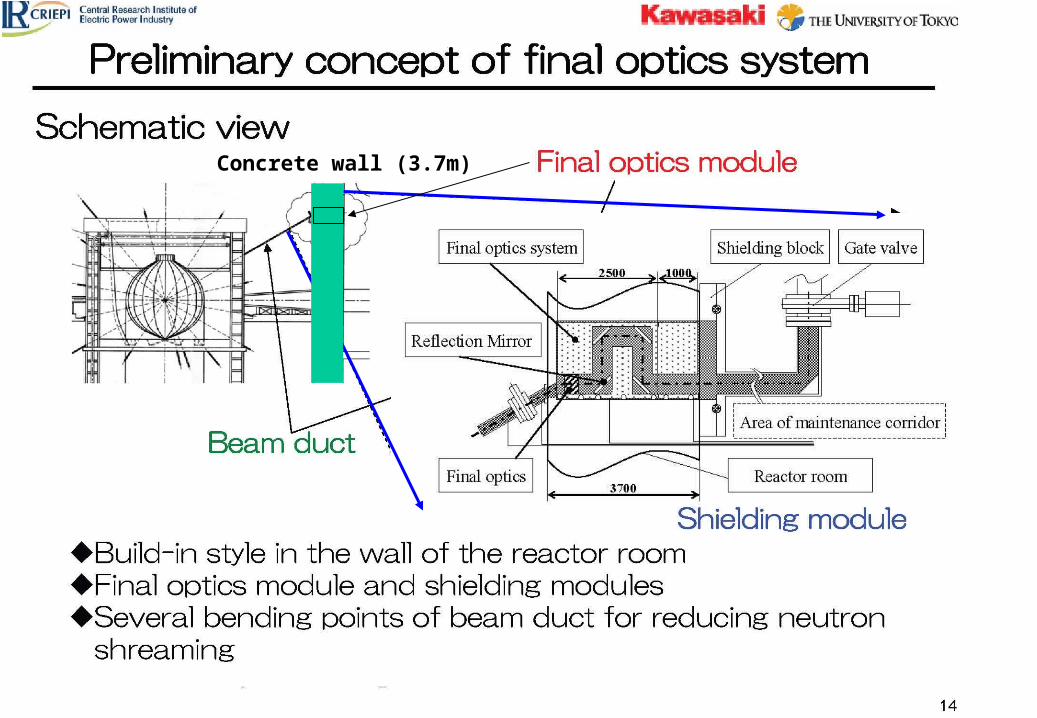
Concrete wall (3.7m)

23
1. Rationale In a fast-ignition scenario a fusion yield in one shot is remarkably redu
ced; typically 1/5 ~ 1/10 as low as that of the central ignition. This might make it possible to introduce a new attractive reactor concept for a laser fusion reactor. Here we have designed FALCON-D with a dry wall concept, so as to make full use of this advantage in the fast ignition scenario.
In FALCON-D reactor, the pellet gain G~100 is feasible with laser energies of 350kJ for implosion, 50kJ for heating, resulting in the fusion yield of 40 MJ in one shot. By increasing the repetition rate up to 30 Hz, the fusion power of 1.2 GWth is available, and the net electric power of about 0.4 GWe is achievable.
2. Core plasma analysis A relatively low aspect ratio pellet with A = 2 ~ 4 is adopted, and the a
chievement of the pellet gain of 80 ~ 100 has been confirmed with a 1-D ILESTA code. A pulse shape of an implosion laser is optimized for a low aspect ratio pellet. The slow implosion velocity is preferable.
Summary
24
3. Dry wall chamber design A dry wall of a ferritic steel with a tungsten armour is employed, and
the feasibility of this dry wall concept is studied from various engineering aspects such as surface melting, physical and chemical sputtering, blistering and exfoliation due to helium retention, and thermo-mechanical fatigue. The UFG-W seems to be attractive for the armour material.
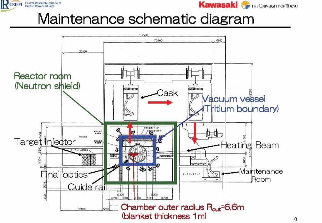
4. Maintenance scenario As for the maintenance scheme the first wall and blanket system is
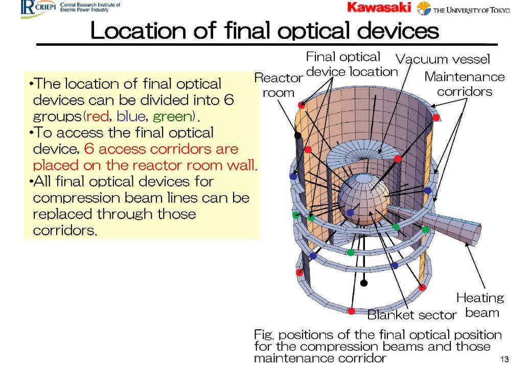
divided into 20 sectors and a large maintenance port is introduced for replacing the blanket sector. The final optics is built in the wall region of the reactor room.
Summary (continued)