Embed Size (px)
Citation preview
1
Update of the injection test
06/2007 nEDM
H. Gao, M. Busch, Q.Ye, T. Mestler, X. Qian, W. Zheng, X. Zhu
Duke University
And others in nEDM collaboration
2
Outline
• Magnets system • collection reservoir
– Pyrex Cell design– Cs coating– monitoring 3He-4He mixture
• Design of Pulsed NMR system

3
Superconducting Magnets
• Tri-coils and solenoid coils– 20G,spin rotation of 45 deg.– 1.2KG, holding field for NMR
• Tri-coil – A bath of liquid He
• Cooling can built by MIT
– June, by Cryomagnetics
• Solenoid coil (Cu:NbTi)– Conductive cooled by Al6061 mandrel– June, by AMI
Tri-coil--Caltech
Solenoid coil

4
Power supply for superconducting solenoid
• A Kepco Power supply with quench protection– Cost reduced by a factor of 10
– Power supply from Superconducting magnet company is an overkill, too expensive
– Pure inductive load,• ~1400V spike voltage at
quenching

5
New design of collection reservoir
• Glass to metal adaptor• Glass joint with kapton O-
ring is hard to seal
• A separated bottom cell– Closer to final test.– Solenoid coil for pNMR is
applicable• Instead of side coil
– Smaller sample size• Longer T2: ~5.5ms
pre-filled 4He
Bottem cell for pNMR
NMR solenoid Probe coil
6
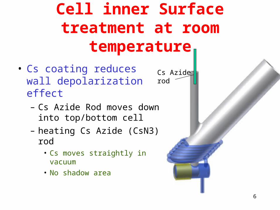
Cell inner Surface treatment at room
temperature• Cs coating reduces wall
depolarization effect– Cs Azide Rod moves
down into top/bottom cell– heating Cs Azide (CsN3)
rod• Cs moves straightly in
vacuum• No shadow area
Cs Aziderod
7
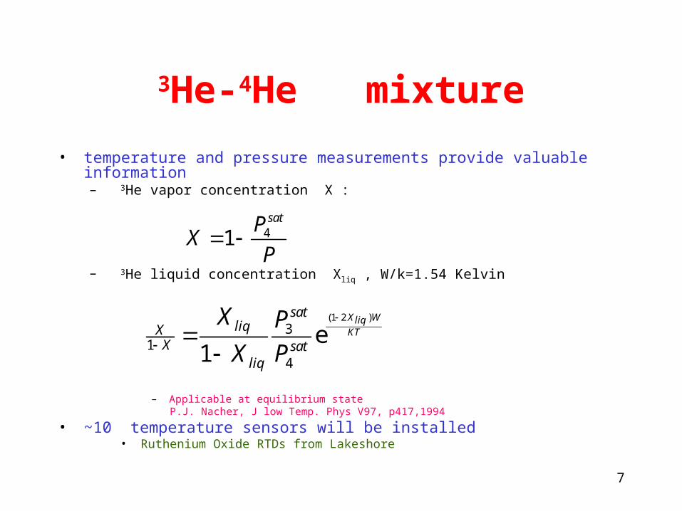
3He-4He mixture
• temperature and pressure measurements provide valuable information – 3He vapor concentration X :
– 3He liquid concentration Xliq , W/k=1.54 Kelvin
– Applicable at equilibrium state P.J. Nacher, J low Temp. Phys V97, p417,1994
• ~10 temperature sensors will be installed• Ruthenium Oxide RTDs from Lakeshore
41satP
XP
(1 2 )3
14
e1
X WliqKT
satliqX
X satliq
X P
X P
8
Polarization measurmnet
• Plused NMR– Resonance frequency at 3.89MHz– Very low density of 3He: 1014atoms/cc
• Very good signal to noise ratio– Must Push what is possible for pNMR– Most helpful to have squids detector
• Will squids work without magnetic shielding?

9
Schematic of pNMR probe
• Signal in the probe coil– >160V during RF transmitter– ~1uV NMR signal of FID
Inside dewar
RF amp
Apollo console from NCSU
10
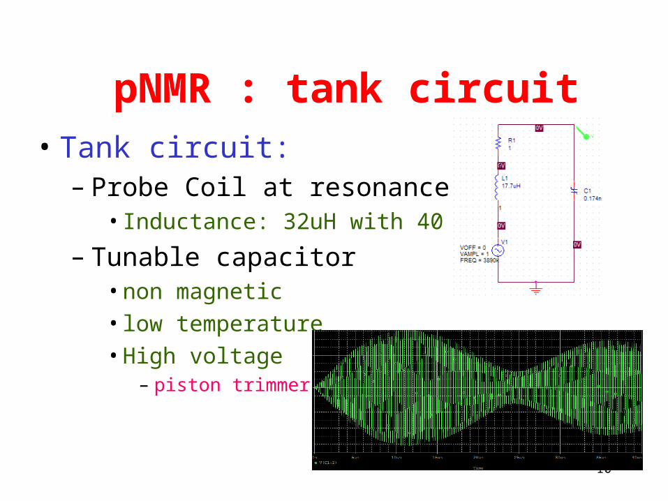
pNMR : tank circuit• Tank circuit:
– Probe Coil at resonance• Inductance: 32uH with 40 turns
– Tunable capacitor• non magnetic• low temperature• High voltage
– piston trimmer

11
Resonance tuning inside dewar
• Piston trimmer close to probe coil
• Very small signal: 1nV/loop • the circulating current does not need to go
through the coax
• Piston trimmer capacitor ordered
– 5~120pF
30 40 50 60 70 80
50
100
150
200
Number of turns
C (pF)

12
Probe of pNMR close to our design
Rev. of Sci. Instr. 68, 2132 (1997).

13
COAX connects the tank circuit
• High-Q Coax cable:– inner: Ag plated BeCu– outer: CuNi – insulated with Teflon
• good electric conductivity• Poor thermal conductivity
Courtesy by Dr. William Halperin, NWU

14
Inhomogeneous B1 field for single solenoid probe
coil
A separate Helmholtz coil for RF power transmitting is under design
Spins rotate by 90 deg.RF pulse duration time: ~100uSB1 field: 7.6G2cm
2cm
15
pNMR: RF amplifier
• From Tomco – Linear amplifier
type: AB– Blanking time
~1us• 1dBm=0.22V
– RF noise:~ 0.2uV
16
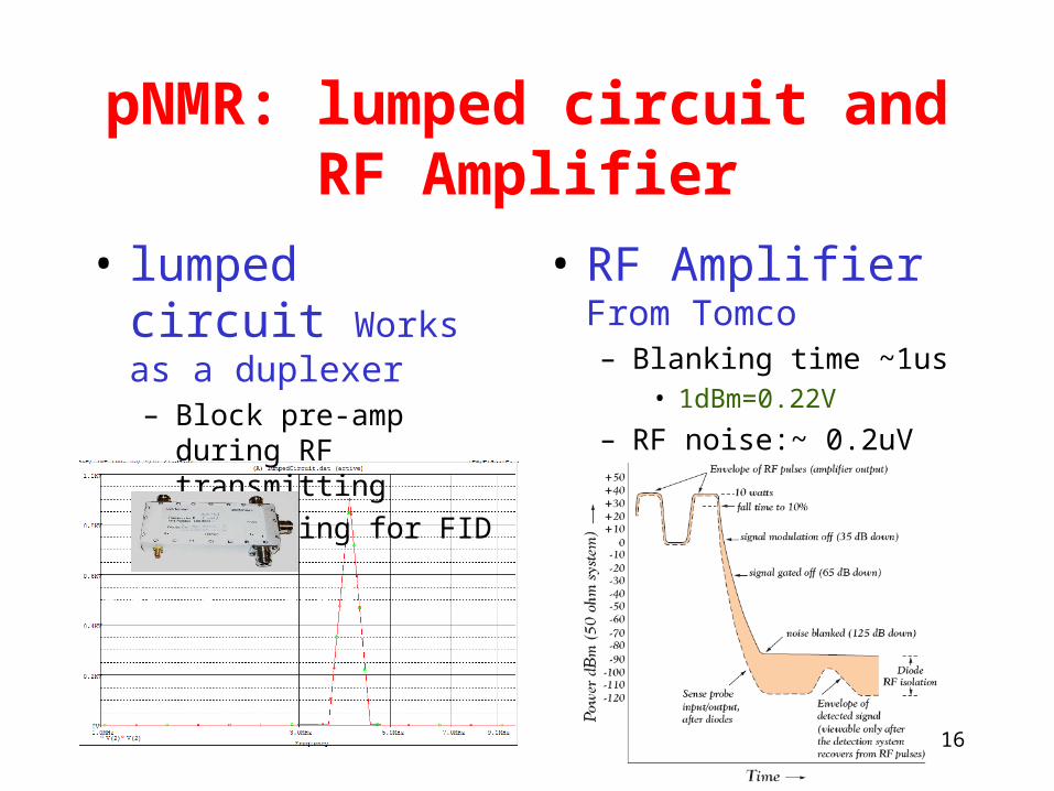
pNMR: lumped circuit and RF Amplifier
• lumped circuit Works as a duplexer – Block pre-amp during
RF transmitting– Conducting for FID
• RF Amplifier From Tomco – Blanking time ~1us
• 1dBm=0.22V
– RF noise:~ 0.2uV
Zi Zo = Z2 = 1/ω2c2

17
Other studies on cryogenic pNMR
• Low noise high impedance Pre-amp
• Q-spoils circuit to shorten the recovery time
• Ground loop • Ultrasonic noise

18
Schedule
• Test and install the magnet system • in June , July and August
• Start pyrex cell fabrication • June and July
• Optimize pNMR system– To see glycerol signal with Apollo console at low field– Improve the signal/noise ratio at room temperature– Cool the sample and tank circuit– improve signal at low temperature
• June , July and August

19
Thanks!

20
Design of Feed through and trimmer handle
BNC-SMA
Hermetically sealed
SMA bulkhead
SMA-coax adaptor
Courtesy by Dr. William Halperin, NWU