Embed Size (px)
Citation preview
1. Table of Contents . . . . . . . . . . . . . . . . . . . . . . . . . . . . . . . . . . . . . . . . . . . . . . . . . . . . . . . . . . . . . . . . . . . . . . . . . . . . . . . . . . . . . . . . . . . . 21.1 0.1 Introduction . . . . . . . . . . . . . . . . . . . . . . . . . . . . . . . . . . . . . . . . . . . . . . . . . . . . . . . . . . . . . . . . . . . . . . . . . . . . . . . . . . . . . . . . . 3
1.1.1 About This Guide . . . . . . . . . . . . . . . . . . . . . . . . . . . . . . . . . . . . . . . . . . . . . . . . . . . . . . . . . . . . . . . . . . . . . . . . . . . . . . . . . . . 41.1.2 Copyright- ProJet ™ XL Finisher . . . . . . . . . . . . . . . . . . . . . . . . . . . . . . . . . . . . . . . . . . . . . . . . . . . . . . . . . . . . . . . . . . . . . . . 51.1.3 Other Useful Documents . . . . . . . . . . . . . . . . . . . . . . . . . . . . . . . . . . . . . . . . . . . . . . . . . . . . . . . . . . . . . . . . . . . . . . . . . . . . . 61.1.4 Special Features . . . . . . . . . . . . . . . . . . . . . . . . . . . . . . . . . . . . . . . . . . . . . . . . . . . . . . . . . . . . . . . . . . . . . . . . . . . . . . . . . . . 7
1.2 0.2 Safety Requirements & Safety Guidelines . . . . . . . . . . . . . . . . . . . . . . . . . . . . . . . . . . . . . . . . . . . . . . . . . . . . . . . . . . . . . . . . . 81.3 0.3 Facility Requirements . . . . . . . . . . . . . . . . . . . . . . . . . . . . . . . . . . . . . . . . . . . . . . . . . . . . . . . . . . . . . . . . . . . . . . . . . . . . . . . . . 9
1.3.1 0.3.1 ProJet™ XL Finisher Physical Specification . . . . . . . . . . . . . . . . . . . . . . . . . . . . . . . . . . . . . . . . . . . . . . . . . . . . . . . . . 101.3.2 0.3.2 ProJet™ XL Finisher Functional Specifications . . . . . . . . . . . . . . . . . . . . . . . . . . . . . . . . . . . . . . . . . . . . . . . . . . . . . . . 111.3.3 Pre-Installation Checklist . . . . . . . . . . . . . . . . . . . . . . . . . . . . . . . . . . . . . . . . . . . . . . . . . . . . . . . . . . . . . . . . . . . . . . . . . . . . . 12
1.4 0.4 Familiarization . . . . . . . . . . . . . . . . . . . . . . . . . . . . . . . . . . . . . . . . . . . . . . . . . . . . . . . . . . . . . . . . . . . . . . . . . . . . . . . . . . . . . . . 131.5 0.5 Installation . . . . . . . . . . . . . . . . . . . . . . . . . . . . . . . . . . . . . . . . . . . . . . . . . . . . . . . . . . . . . . . . . . . . . . . . . . . . . . . . . . . . . . . . . . 14
1.5.1 05.1 Unpacking and Inspection . . . . . . . . . . . . . . . . . . . . . . . . . . . . . . . . . . . . . . . . . . . . . . . . . . . . . . . . . . . . . . . . . . . . . . . . 151.5.2 05.2 Setup . . . . . . . . . . . . . . . . . . . . . . . . . . . . . . . . . . . . . . . . . . . . . . . . . . . . . . . . . . . . . . . . . . . . . . . . . . . . . . . . . . . . . . . . 16
1.6 0.6 Operation . . . . . . . . . . . . . . . . . . . . . . . . . . . . . . . . . . . . . . . . . . . . . . . . . . . . . . . . . . . . . . . . . . . . . . . . . . . . . . . . . . . . . . . . . . 171.6.1 0.6.5 Temp CONTROL Settings . . . . . . . . . . . . . . . . . . . . . . . . . . . . . . . . . . . . . . . . . . . . . . . . . . . . . . . . . . . . . . . . . . . . . . . 181.6.2 0.6.6 Parameter Programming Mode . . . . . . . . . . . . . . . . . . . . . . . . . . . . . . . . . . . . . . . . . . . . . . . . . . . . . . . . . . . . . . . . . . . 19
1.6.2.1 Operating Parameters . . . . . . . . . . . . . . . . . . . . . . . . . . . . . . . . . . . . . . . . . . . . . . . . . . . . . . . . . . . . . . . . . . . . . . . . . . 201.6.2.2 Set-Up Parameters . . . . . . . . . . . . . . . . . . . . . . . . . . . . . . . . . . . . . . . . . . . . . . . . . . . . . . . . . . . . . . . . . . . . . . . . . . . . 21
1.6.3 0.6.7 Finisher Zone Calibration . . . . . . . . . . . . . . . . . . . . . . . . . . . . . . . . . . . . . . . . . . . . . . . . . . . . . . . . . . . . . . . . . . . . . . . . 221.6.4 0.6.8 HI LIMIT Control Settings . . . . . . . . . . . . . . . . . . . . . . . . . . . . . . . . . . . . . . . . . . . . . . . . . . . . . . . . . . . . . . . . . . . . . . . . 23
1.6.4.1 Changing Display From C To F for Hi-Limit Control . . . . . . . . . . . . . . . . . . . . . . . . . . . . . . . . . . . . . . . . . . . . . . . . . . . 241.6.5 0.6.9 Parameter Setup Mode . . . . . . . . . . . . . . . . . . . . . . . . . . . . . . . . . . . . . . . . . . . . . . . . . . . . . . . . . . . . . . . . . . . . . . . . . 25
1.6.5.1 Setup Parameters . . . . . . . . . . . . . . . . . . . . . . . . . . . . . . . . . . . . . . . . . . . . . . . . . . . . . . . . . . . . . . . . . . . . . . . . . . . . . 261.6.6 06.10 Changing Display From °C To °F . . . . . . . . . . . . . . . . . . . . . . . . . . . . . . . . . . . . . . . . . . . . . . . . . . . . . . . . . . . . . . . . . 271.6.7 06.11 Removing Parts from the Finisher . . . . . . . . . . . . . . . . . . . . . . . . . . . . . . . . . . . . . . . . . . . . . . . . . . . . . . . . . . . . . . . . . 281.6.8 06.12 Emptying the Tray . . . . . . . . . . . . . . . . . . . . . . . . . . . . . . . . . . . . . . . . . . . . . . . . . . . . . . . . . . . . . . . . . . . . . . . . . . . . . 291.6.9 06.13 Finisher Shutdown . . . . . . . . . . . . . . . . . . . . . . . . . . . . . . . . . . . . . . . . . . . . . . . . . . . . . . . . . . . . . . . . . . . . . . . . . . . . . 301.6.10 0.6.1 Theory of Operation . . . . . . . . . . . . . . . . . . . . . . . . . . . . . . . . . . . . . . . . . . . . . . . . . . . . . . . . . . . . . . . . . . . . . . . . . . . 31
1.6.10.1 Oven Theory . . . . . . . . . . . . . . . . . . . . . . . . . . . . . . . . . . . . . . . . . . . . . . . . . . . . . . . . . . . . . . . . . . . . . . . . . . . . . . . . 321.6.10.2 HI-LIMIT Instrument . . . . . . . . . . . . . . . . . . . . . . . . . . . . . . . . . . . . . . . . . . . . . . . . . . . . . . . . . . . . . . . . . . . . . . . . . . . 331.6.10.3 TEMP CONTROL Instrument . . . . . . . . . . . . . . . . . . . . . . . . . . . . . . . . . . . . . . . . . . . . . . . . . . . . . . . . . . . . . . . . . . . 34
1.6.11 0.6.2 Before Starting . . . . . . . . . . . . . . . . . . . . . . . . . . . . . . . . . . . . . . . . . . . . . . . . . . . . . . . . . . . . . . . . . . . . . . . . . . . . . . . 351.6.11.1 Pre-Startup Checklist . . . . . . . . . . . . . . . . . . . . . . . . . . . . . . . . . . . . . . . . . . . . . . . . . . . . . . . . . . . . . . . . . . . . . . . . . . 36
1.6.12 0.6.3 Loading Parts in the Finisher . . . . . . . . . . . . . . . . . . . . . . . . . . . . . . . . . . . . . . . . . . . . . . . . . . . . . . . . . . . . . . . . . . . . 371.6.13 0.6.4 Finisher Start Up . . . . . . . . . . . . . . . . . . . . . . . . . . . . . . . . . . . . . . . . . . . . . . . . . . . . . . . . . . . . . . . . . . . . . . . . . . . . . 38
1.7 0.7 Maintenance . . . . . . . . . . . . . . . . . . . . . . . . . . . . . . . . . . . . . . . . . . . . . . . . . . . . . . . . . . . . . . . . . . . . . . . . . . . . . . . . . . . . . . . . 391.7.1 07.4 How to Replace the HILIMIT Control . . . . . . . . . . . . . . . . . . . . . . . . . . . . . . . . . . . . . . . . . . . . . . . . . . . . . . . . . . . . . . . . 401.7.2 07.5 How to Replace the Heater . . . . . . . . . . . . . . . . . . . . . . . . . . . . . . . . . . . . . . . . . . . . . . . . . . . . . . . . . . . . . . . . . . . . . . . 411.7.3 07.6 How to Replace the Fan Motor . . . . . . . . . . . . . . . . . . . . . . . . . . . . . . . . . . . . . . . . . . . . . . . . . . . . . . . . . . . . . . . . . . . . 421.7.4 07.7 Replacement Parts . . . . . . . . . . . . . . . . . . . . . . . . . . . . . . . . . . . . . . . . . . . . . . . . . . . . . . . . . . . . . . . . . . . . . . . . . . . . . 431.7.5 07.3 How to Replace the TEMP Control . . . . . . . . . . . . . . . . . . . . . . . . . . . . . . . . . . . . . . . . . . . . . . . . . . . . . . . . . . . . . . . . . 441.7.6 0.7.1 Checklist . . . . . . . . . . . . . . . . . . . . . . . . . . . . . . . . . . . . . . . . . . . . . . . . . . . . . . . . . . . . . . . . . . . . . . . . . . . . . . . . . . . . . 451.7.7 07.2 Testing . . . . . . . . . . . . . . . . . . . . . . . . . . . . . . . . . . . . . . . . . . . . . . . . . . . . . . . . . . . . . . . . . . . . . . . . . . . . . . . . . . . . . . . 46
1.8 0.8 Troubleshooting . . . . . . . . . . . . . . . . . . . . . . . . . . . . . . . . . . . . . . . . . . . . . . . . . . . . . . . . . . . . . . . . . . . . . . . . . . . . . . . . . . . . . 471.9 0.9 Spare Part List . . . . . . . . . . . . . . . . . . . . . . . . . . . . . . . . . . . . . . . . . . . . . . . . . . . . . . . . . . . . . . . . . . . . . . . . . . . . . . . . . . . . . . 49
Table of Contents
0.1 Introduction
About This GuideCopyright- ProJet ™ XL FinisherOther Useful DocumentsSpecial Features
0.2 Safety Requirements & Safety Guidelines
0.3 Facility Requirements
0.3.1 ProJet™ XL Finisher Physical Specification0.3.2 ProJet™ XL Finisher Functional SpecificationsPre-Installation Checklist
0.4 Familiarization
0.5 Installation
05.1 Unpacking and Inspection05.2 Setup
0.6 Operation
0.6.1 Theory of Operation0.6.2 Before Starting0.6.3 Loading Parts in the Finisher0.6.4 Finisher Start Up0.6.5 Temp CONTROL Settings0.6.6 Parameter Programming Mode0.6.7 Finisher Zone Calibration0.6.8 HI LIMIT Control Settings0.6.9 Parameter Setup Mode06.10 Changing Display From °C To °F06.11 Removing Parts from the Finisher06.12 Emptying the Tray06.13 Finisher Shutdown
0.7 Maintenance
0.7.1 Checklist07.2 Testing07.3 How to Replace the TEMP Control07.4 How to Replace the HILIMIT Control07.5 How to Replace the Heater07.6 How to Replace the Fan Motor07.7 Replacement Parts
0.8 Troubleshooting
0.9 Spare Part List

0.1 Introduction3D Systems would like to congratulate you on the purchase of the ProJet™ XL Finisher. We pride ourselves in our ability to offer our customersthe latest idea in parts finishing solutions. We at 3D Systems are confident that your system will provide valuable service for many years to come.
About This GuideCopyright- ProJet ™ XL FinisherOther Useful DocumentsSpecial Features

About This Guide
This guide will help you:
Understand all safety aspects when operating the system and when handling partially-cured material.Prepare your facility for the finisher installationUnderstand how the finisher worksProperly unpack and set up the finisherUnderstand how to operate and properly maintain the finisherUnderstand the part finishing processes
Copyright- ProJet ™ XL Finisher
©2010 by 3D Systems®, All rights reserved.
Under the copyright laws, this user guide may not be copied, in whole or in part, without the written consent of 3D Systems®. The ProJet ™ logois a trademark of 3D Systems®. Use of this logo without the prior written consent of 3D Systems® may constitute trademark infringement andunfair competition in violation of federal and state laws.
Every effort has been made to ensure that the information in this manual is accurate. Other company and product names mentioned herein aretrademarks of their respective companies. Mention of third-party products is for informational purposes only and constitutes neither anendorsement nor a recommendation.
The product described in this user guide incorporates copyright protection technology that is protected by method claims of certain U.S. patentsand other intellectual property rights that are owned by 3D Systems®. Reverse engineering is prohibited.
ProJet ™ XL Finisher provides professional, convenient and complete post-curing of parts that are produced from the 3-D modeler system. Itdoes not require a special technical staff to supervise the system. All design and process considerations are compatible with an RP environment.

Other Useful Documents
VisiJet® Material Handling Guide - The Material Handling Guide provides the information you need to safely manage your inventory of VisiJet®material for the ProJet™ 3-D Modelers. It also provides valuable application and operating tips, part finishing instructions, and troubleshootinginformation to help you build robust and aesthetically pleasing parts with VisiJet® material.VisiJet® Material Safety Data Sheets (MSDS's) – These are online copies of the printed VisiJet® model material MSDS and VisiJet® supportmaterial MSDS that ship with VisiJet® materials. Make sure everyone in your facility who handles VisiJet® materials reads these MSDS's andfollows the safety guidelines in them.

Special Features
The sturdy construction and high grade insulation of the ProJet Finisher XL contributes to excellent high temperature performance. Other specialfeatures include: * Proportional digital CONTROL instrument to control temperature fluctuations.
Manual reset HI-LIMIT instrument to protect the chamber workload as well as the finisher itself.Unique design to combine forced circulated air through side ducts for the ultimate in temperature performance.Welded double wall construction and fiberglass insulation to reduce heat loss.Silicone rubber gaskets further minimize heat leakage.Scratch-resistant baked enamel exterior and stainless steel interior for easy cleaning.Space-saving, stackable design.
0.2 Safety Requirements & Safety Guidelines
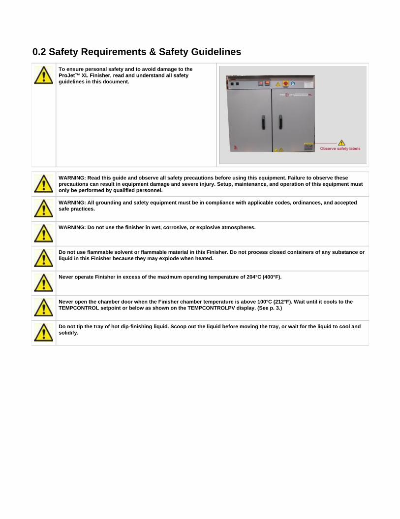
To ensure personal safety and to avoid damage to theProJet™ XL Finisher, read and understand all safetyguidelines in this document.
WARNING: Read this guide and observe all safety precautions before using this equipment. Failure to observe theseprecautions can result in equipment damage and severe injury. Setup, maintenance, and operation of this equipment mustonly be performed by qualified personnel.
WARNING: All grounding and safety equipment must be in compliance with applicable codes, ordinances, and acceptedsafe practices.
WARNING: Do not use the finisher in wet, corrosive, or explosive atmospheres.
Do not use flammable solvent or flammable material in this Finisher. Do not process closed containers of any substance orliquid in this Finisher because they may explode when heated.
Never operate Finisher in excess of the maximum operating temperature of 204°C (400°F).
Never open the chamber door when the Finisher chamber temperature is above 100°C (212°F). Wait until it cools to theTEMPCONTROL setpoint or below as shown on the TEMPCONTROLPV display. (See p. 3.)
Do not tip the tray of hot dip-finishing liquid. Scoop out the liquid before moving the tray, or wait for the liquid to cool andsolidify.

0.3 Facility Requirements0.3.1 ProJet™ XL Finisher Physical Specification0.3.2 ProJet™ XL Finisher Functional SpecificationsPre-Installation Checklist
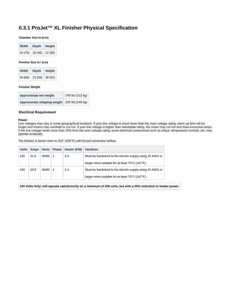
0.3.1 ProJet™ XL Finisher Physical Specification
Chamber Size in./(cm)
Width Depth Height
30 (76) 18 (46) 22 (56)
Finisher Size in / (cm)
Width Depth Height
34 (86) 23 (58) 36 (91)
Finisher Weight
Approximate net weight 245 lbs (112 kg)
Approximate shipping weight 320 lbs (146 kg)
Electrical Requirement
PowerLine voltages may vary in some geographical locations. If your line voltage is much lower than the oven voltage rating, warm up time will belonger and motors may overload or run hot. If your line voltage is higher than nameplate rating, the motor may run hot and draw excessive amps.If the line voltage varies more than 10% from the oven voltage rating, some electrical components such as relays, temperature controls, etc. mayoperate erratically.
The finisher is bench oven to 204° (400°F) with forced convention airflow.
Volts Amps Hertz Phase Heater (KW) Hardwire
120 21.6 50/60 1 2.4 Must be hardwired to the electric supply using 10 AWG or
larger wires suitable for at least 75°C (167°F).
240 10.8 50/60 1 2.4 Must be hardwired to the electric supply using 10 AWG or
larger wires suitable for at least 75°C (167°F).
240 Volts Only: will operate satisfactorily on a minimum of 208 volts, but with a 25% reduction in heater power.
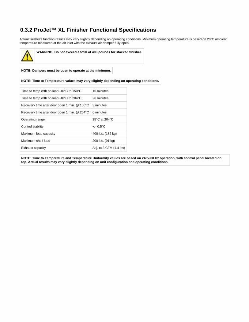
0.3.2 ProJet™ XL Finisher Functional Specifications
Actual finisher's function results may vary slightly depending on operating conditions. Minimum operating temperature is based on 20ºC ambienttemperature measured at the air inlet with the exhaust air damper fully open.
WARNING: Do not exceed a total of 400 pounds for stacked finisher.
NOTE: Dampers must be open to operate at the minimum.
NOTE: Time to Temperature values may vary slightly depending on operating conditions.
Time to temp with no load- 40°C to 150°C 15 minutes
Time to temp with no load- 40°C to 204°C 26 minutes
Recovery time after door open 1 min. @ 150°C 3 minutes
Recovery time after door open 1 min. @ 204°C 6 minutes
Operating range 35°C at 204°C
Control stability +/- 0.5°C
Maximum load capacity 400 lbs. (182 kg)
Maximum shelf load 200 lbs. (91 kg)
Exhaust capacity Adj. to 3 CFM (1.4 lps)
NOTE: Time to Temperature and Temperature Uniformity values are based on 240V/60 Hz operation, with control panel located ontop. Actual results may vary slightly depending on unit configuration and operating conditions.
Pre-Installation Checklist
Read this guide carefully. Make use of its instructions and explanations. Safe, continuous, satisfactory, trouble-free operation dependsprimarily on how well you understand and maintain the Finisher.
Verify line voltage. Your facility's line voltage must correspond to the voltage shown on the Finisher's nameplate. See 0.3.1 ProJet™ XL .Finisher Physical Specification
Verify clearance. You need at least 8 cm (3 in) of clearance at the Finisher's sides, and 5 cm (2 in) clearance at the rear of the Finisher toensure adequate air circulation, component cooling, and effective temperature control. Take special care to not block the openings on thesides and rear of the Finisher.
The table, bench, or stand you place the Finisher on must be stable, level, and able to support 78kg (172lb), the weight of the Finisherplus a full tray of VisiJet support material and 9kg(20lb) of VisiJet parts on the shelf.
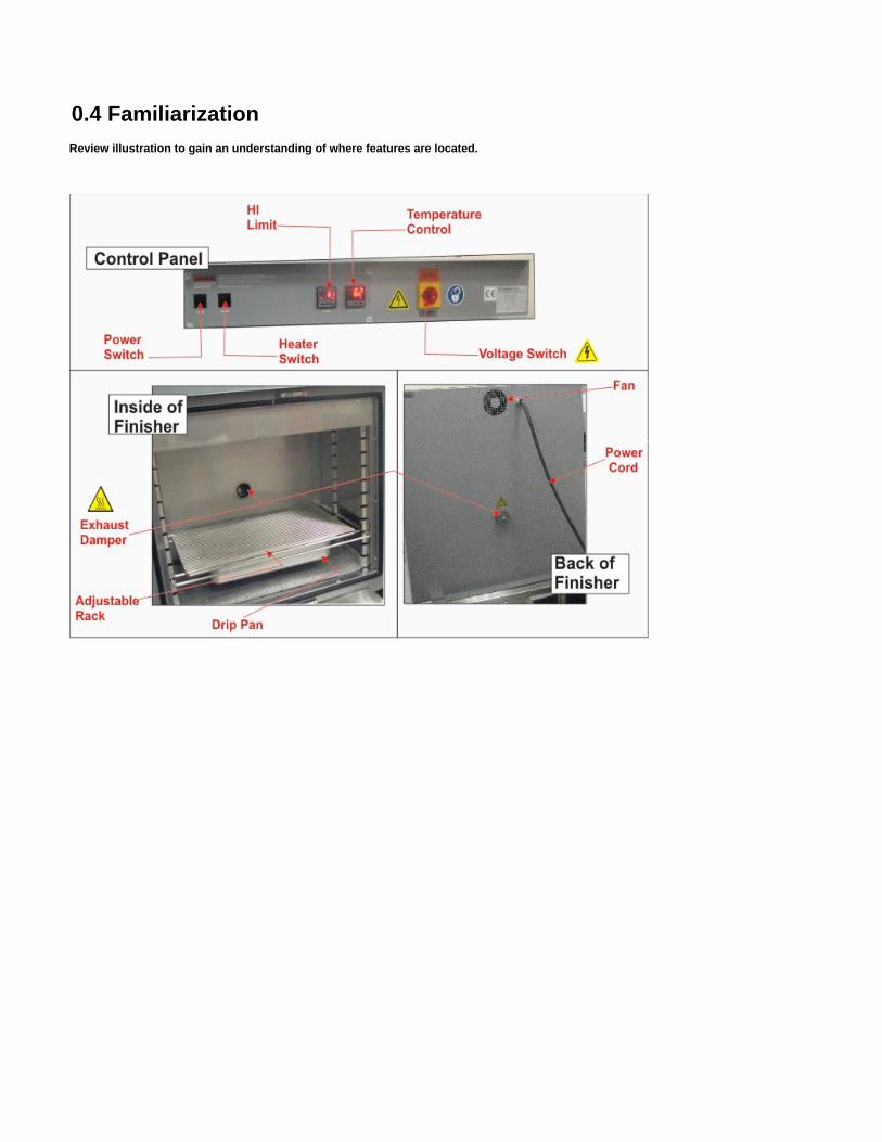
0.4 FamiliarizationReview illustration to gain an understanding of where features are located.

0.5 InstallationThis section describes unpacking and how to set up the finisher for operation. Ensure that all facility requirements are met to ensure optimumperformance when operating.
05.1 Unpacking and Inspection05.2 Setup
05.1 Unpacking and Inspection
Remove all packing materials and thoroughly inspect the oven for damage of any kind that could have occurred during shipment.
Ensure the carton and plastic cover sheet inside carton are still in good condition.Look at all outside surfaces and corners of the oven for scratches and dents.Check the panel control function to ensure it is working properly.Check the door and latch for smooth operation.
If damage exist or if items are missing from packaging, contact .3D Systems Customer Support
Your shipment should include:
One (1) ProJet XL FinisherTwo (2) ShelvesOne (1) Damper assembly
Accessory Kit Contains:
One (1) Set of glovesOne (1) Declarations of ConformityOne (1) Box of KimwipesOne (1) Set of TogglesTwo (1) Rolls of pads
05.2 Setup
WARNING: All grounding and safety equipment must be in compliance with applicable codes, ordinances and acceptedsafe practices.
Place finisher on a bench top or an stand. The oven must have a minimum of two (2) inches (5 cm) clearance in the rear to provideproper ventilation.The finisher may be placed next to another cabinet, or next to another oven, with three (3) inch (8 cm) clearance (the doors will stillopen).Make sure finisher is level; this will assure proper heat distribution and operation of all mechanical components.Identify correct power source indicated on the specification plate.
All grounding and safety equipment must be in compliance with applicable codes, ordinances and accepted safepractices.
PowerLine voltages may vary in some geographical locations. If your line voltage is much lower than the oven voltage rating, warm up time will belonger and motors may overload or run hot. If your line voltage is higher than nameplate rating, the motor may run hot and draw excessive amps.If the line voltage varies more than 10% from the oven voltage rating, some electrical components such as relays, temperature controls, etc. mayoperate erratically.
Hard wire oven directly to the electric supply .(see Electrical Specifications)
0.6 OperationThis section describes how to load parts in the finisher when you are ready to remove bulk support material. It also describes how to start finishingcycle and provides detailed operating instructions for the TEMP CONTROL and HI LIMIT control.
Do not use the finisher in wet, corrosive, or explosive atmospheres. Users in the United States must comply withOccupational Safety and Health Act (OSHA) of 1970, Section 5, and all relevant local safety rules and regulations. Refer tothe OSHA and National Fire Protection Association (NFPA) safety standards for further information.
Before You Start a Finisher Cycle
Read this User's Guide. Carefully follow all of its safety, operation, and maintenance instructions.Verify line voltage. It must match to the voltage shown on the nameplate, see "Power requirements."Verify fresh air, exhaust, and electrical cabinet openings. Remove any restrictions in or near the fresh air and exhaust openings. Never letthem become clogged to the point they impede air flow.The damper may need to be opened for the Finisher to operate properly in the 70°C to 75°C temperature range for VisiJet parts.Put on gloves.
IRRITANT! A small amount of uncured VisiJet model material might be on the surface of a part when you remove it fromthe modeler. Repeated skin contact with uncured VisiJet model material can cause allergic skin irritation or rash. Washhands with soap and water if you contact VisiJet model material. For further safety information, see your VisiJet MaterialHandling Guide and the VisiJet model material MSDS.
0.6.1 Theory of Operation0.6.2 Before Starting0.6.3 Loading Parts in the Finisher0.6.4 Finisher Start Up0.6.5 Temp CONTROL Settings0.6.6 Parameter Programming Mode0.6.7 Finisher Zone Calibration0.6.8 HI LIMIT Control Settings0.6.9 Parameter Setup Mode06.10 Changing Display From °C To °F06.11 Removing Parts from the Finisher06.12 Emptying the Tray06.13 Finisher Shutdown
1. 2.
3.
4.
0.6.5 Temp CONTROL Settings
The Finisher has been tested and preset at the factory for normal operating conditions. In most applications, it will not be necessary to alter theFinisher's settings, except for the TEMP CONTROL setpoint. This section contains information and reference material to change the setpoint,change the display from°C to°F, and access the control's operating and set-up parameters.The TEMP CONTROL was carefully programmed at the factory. The parameters that may be accessed include tuning functions, displayfunctions, and thermocouple selection. If you need to recalibrate the TEMP CONTROL for a specific operating condition, see "Recalibrating theTEMP CONTROL."
How to view and change the TEMP CONTROL setpoint
CAUTION: Never operate Finisher at a temperature in excess of the maximum operating temperature of 204°C (400°F).
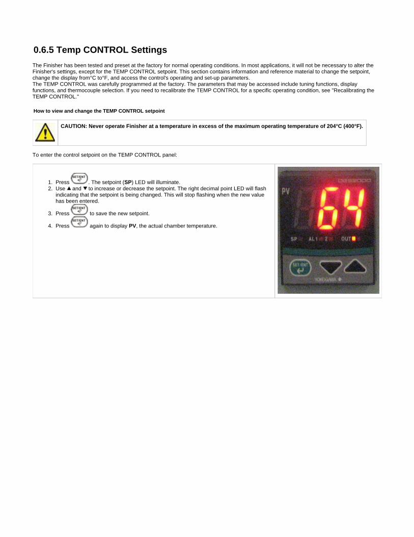
To enter the control setpoint on the TEMP CONTROL panel:
Press . The setpoint ( ) LED will illuminate.SPUse and to increase or decrease the setpoint. The right decimal point LED will flashindicating that the setpoint is being changed. This will stop flashing when the new valuehas been entered.
Press to save the new setpoint.
Press again to display , the actual chamber temperature.PV
1.
2.
3. 4.
5.
6.
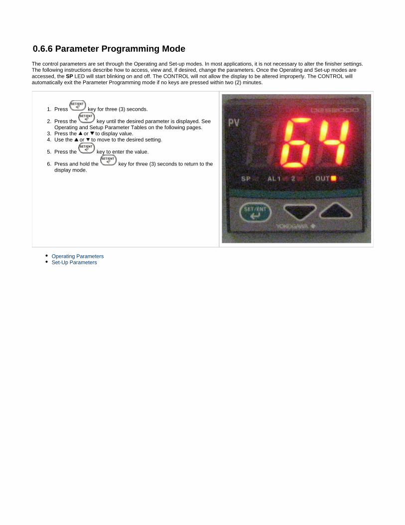
0.6.6 Parameter Programming Mode
The control parameters are set through the Operating and Set-up modes. In most applications, it is not necessary to alter the finisher settings.The following instructions describe how to access, view and, if desired, change the parameters. Once the Operating and Set-up modes areaccessed, the LED will start blinking on and off. The CONTROL will not allow the display to be altered improperly. The CONTROL willSPautomatically exit the Parameter Programming mode if no keys are pressed within two (2) minutes.
Press key for three (3) seconds.
Press the key until the desired parameter is displayed. SeeOperating and Setup Parameter Tables on the following pages.Press the or to display value.Use the or to move to the desired setting.
Press the key to enter the value.
Press and hold the key for three (3) seconds to return to thedisplay mode.
Operating ParametersSet-Up Parameters
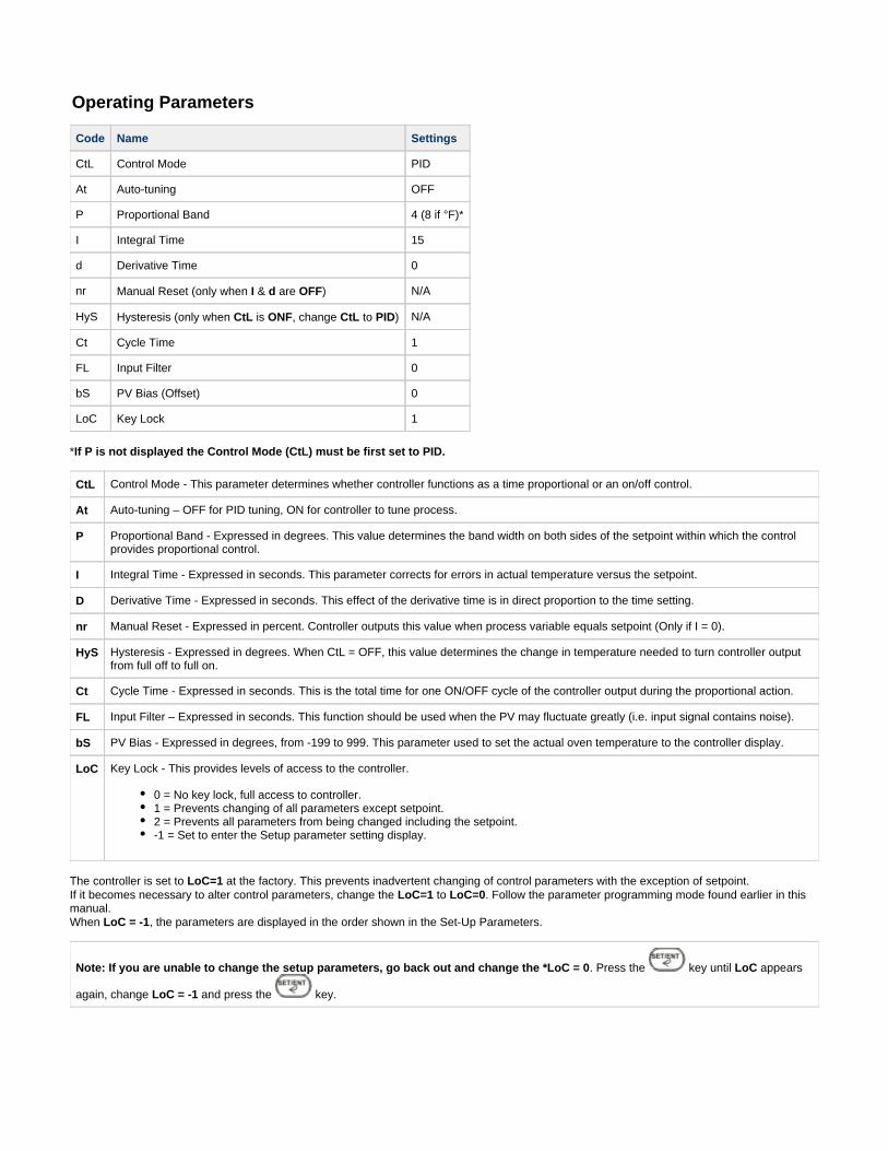
Operating Parameters
Code Name Settings
CtL Control Mode PID
At Auto-tuning OFF
P Proportional Band 4 (8 if °F)*
I Integral Time 15
d Derivative Time 0
nr Manual Reset (only when & are )I d OFF N/A
HyS Hysteresis (only when is , change to )CtL ONF CtL PID N/A
Ct Cycle Time 1
FL Input Filter 0
bS PV Bias (Offset) 0
LoC Key Lock 1
* If P is not displayed the Control Mode (CtL) must be first set to PID.
CtL Control Mode - This parameter determines whether controller functions as a time proportional or an on/off control.
At Auto-tuning – OFF for PID tuning, ON for controller to tune process.
P Proportional Band - Expressed in degrees. This value determines the band width on both sides of the setpoint within which the controlprovides proportional control.
I Integral Time - Expressed in seconds. This parameter corrects for errors in actual temperature versus the setpoint.
D Derivative Time - Expressed in seconds. This effect of the derivative time is in direct proportion to the time setting.
nr Manual Reset - Expressed in percent. Controller outputs this value when process variable equals setpoint (Only if I = 0).
HyS Hysteresis - Expressed in degrees. When CtL = OFF, this value determines the change in temperature needed to turn controller outputfrom full off to full on.
Ct Cycle Time - Expressed in seconds. This is the total time for one ON/OFF cycle of the controller output during the proportional action.
FL Input Filter – Expressed in seconds. This function should be used when the PV may fluctuate greatly (i.e. input signal contains noise).
bS PV Bias - Expressed in degrees, from -199 to 999. This parameter used to set the actual oven temperature to the controller display.
LoC Key Lock - This provides levels of access to the controller.
0 = No key lock, full access to controller.1 = Prevents changing of all parameters except setpoint.2 = Prevents all parameters from being changed including the setpoint.-1 = Set to enter the Setup parameter setting display.
The controller is set to at the factory. This prevents inadvertent changing of control parameters with the exception of setpoint. LoC=1If it becomes necessary to alter control parameters, change the to . Follow the parameter programming mode found earlier in thisLoC=1 LoC=0manual. When , the parameters are displayed in the order shown in the Set-Up Parameters.LoC = -1
Note: If you are unable to change the setup parameters, go back out and change the *LoC = 0. Press the key until appearsLoC
again, change and press the key.LoC = -1
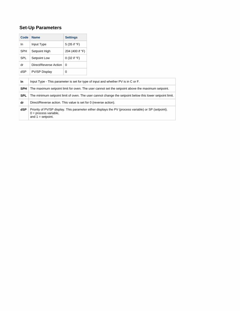
Set-Up Parameters
Code Name Settings
In Input Type 5 (35 if °F)
SPH Setpoint High 204 (400 if °F)
SPL Setpoint Low 0 (32 if °F)
dr Direct/Reverse Action 0
dSP PV/SP Display 0
In Input Type - This parameter is set for type of input and whether PV is in C or F.
SPH The maximum setpoint limit for oven. The user cannot set the setpoint above the maximum setpoint.
SPL The minimum setpoint limit of oven. The user cannot change the setpoint below this lower setpoint limit.
dr Direct/Reverse action. This value is set for 0 (reverse action).
dSP Priority of PV/SP display. This parameter either displays the PV (process variable) or SP (setpoint). 0 = process variable,and 1 = setpoint.
1.
2. 3.
4.
5.
0.6.7 Finisher Zone Calibration
The CONTROL instrument has been tested and calibrated at the factory. Under normal operating conditions, recalibration should not benecessary. However, if the user would like to recalibrate the CONTROL for a specific operating condition, then recalibration is easilyaccomplished.
Calibration Instructions
*Required Equipment:*
Temperature Measuring Device with a Compatible Temperature Sensor
Verify that the (PV Bias) programmed in the CONTROL is . Refer to Instructions on viewing the parameter in the PARAMETERbS 0PROGRAMMING mode.Locate the temperature sensor of the temperature measuring device at the center of the chamber.Operate the oven until it reaches the desired operating temperature and the CONTROL is regulating. The user may wish to have aloaded chamber with a standard amount of product to simulate a specific operating condition. It will take several minutes for the unit tostabilize at the controlled temperature. Allow at least 30 minutes of operation at the stabilized temperature before proceeding.Subtract the average controlled temperature (number appearing on the CONTROL display) from the actual oven temperature (numberappearing on the temperature measuring device display). The CONTROL and the device must be in the same scale (°C or °F).Actual Oven Temperature - Controlled Temperature = calculated valueEnter the calculated value from Step 4 as the new bS (PV Bias) value in the instrument.
0.6.8 HI LIMIT Control Settings
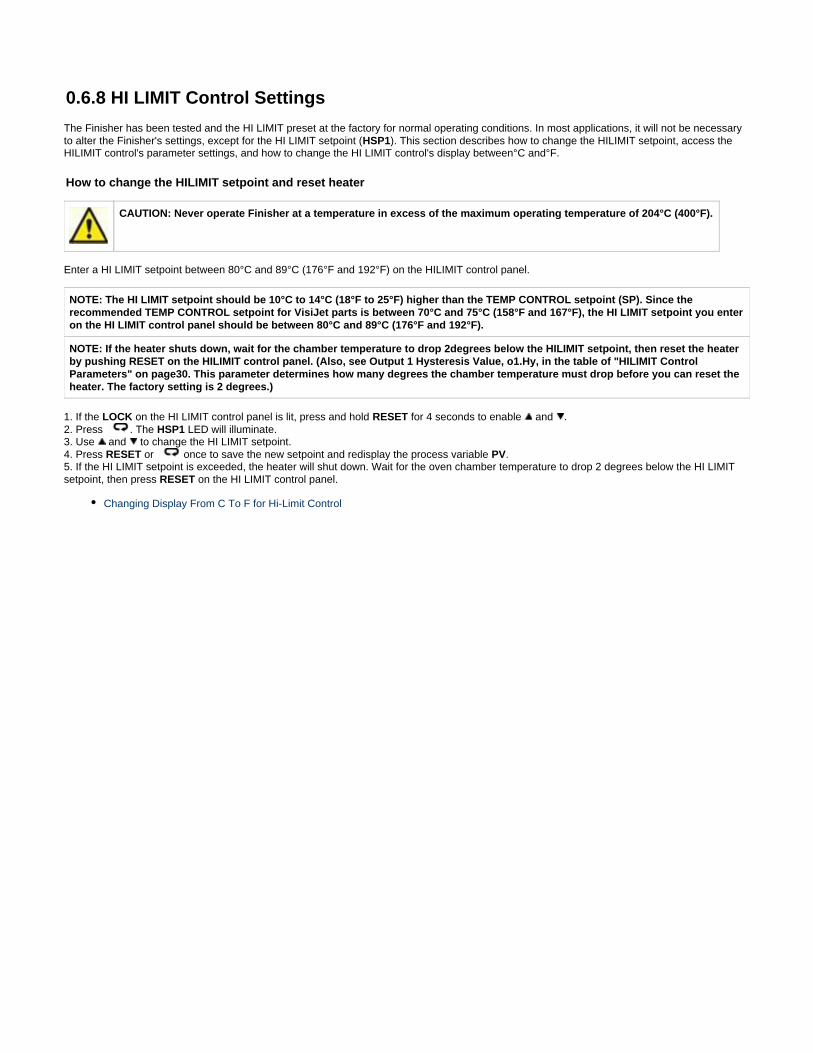
The Finisher has been tested and the HI LIMIT preset at the factory for normal operating conditions. In most applications, it will not be necessaryto alter the Finisher's settings, except for the HI LIMIT setpoint ( ). This section describes how to change the HILIMIT setpoint, access theHSP1HILIMIT control's parameter settings, and how to change the HI LIMIT control's display between°C and°F.
How to change the HILIMIT setpoint and reset heater
CAUTION: Never operate Finisher at a temperature in excess of the maximum operating temperature of 204°C (400°F).
Enter a HI LIMIT setpoint between 80°C and 89°C (176°F and 192°F) on the HILIMIT control panel.
NOTE: The HI LIMIT setpoint should be 10°C to 14°C (18°F to 25°F) higher than the TEMP CONTROL setpoint (SP). Since therecommended TEMP CONTROL setpoint for VisiJet parts is between 70°C and 75°C (158°F and 167°F), the HI LIMIT setpoint you enteron the HI LIMIT control panel should be between 80°C and 89°C (176°F and 192°F).
NOTE: If the heater shuts down, wait for the chamber temperature to drop 2degrees below the HILIMIT setpoint, then reset the heaterby pushing RESET on the HILIMIT control panel. (Also, see Output 1 Hysteresis Value, o1.Hy, in the table of "HILIMIT ControlParameters" on page30. This parameter determines how many degrees the chamber temperature must drop before you can reset theheater. The factory setting is 2 degrees.)
1. If the on the HI LIMIT control panel is lit, press and hold for 4 seconds to enable and . LOCK RESET2. Press . The LED will illuminate.HSP13. Use and to change the HI LIMIT setpoint.4. Press or once to save the new setpoint and redisplay the process variable .RESET PV5. If the HI LIMIT setpoint is exceeded, the heater will shut down. Wait for the oven chamber temperature to drop 2 degrees below the HI LIMITsetpoint, then press on the HI LIMIT control panel.RESET
Changing Display From C To F for Hi-Limit Control
1. 2. 3. 4. 5. 6. 7. 8.
Changing Display From C To F for Hi-Limit Control
The HI-LIMIT can be configured for either °C or °F.Use the following steps to change HI-LIMIT from displaying °C to °F (and for changing back to °C).
If the on the HI-LIMIT is lit, press and hold the for four (4) seconds to enable the and keys.RESETPress and hold the key for four (4) seconds, the setup mode has now been entered.Press the key until the unit is displayed.Press the or to display value.Use the or to move to the desired setting.Press the key, this enters the value and advances to the next parameter.Press the , this will return the HI-LIMIT to the normal mode.RESETThe HI-LIMIT has been changed, enter the desired setpoint.
1. 2. 3. 4. 5. 6.
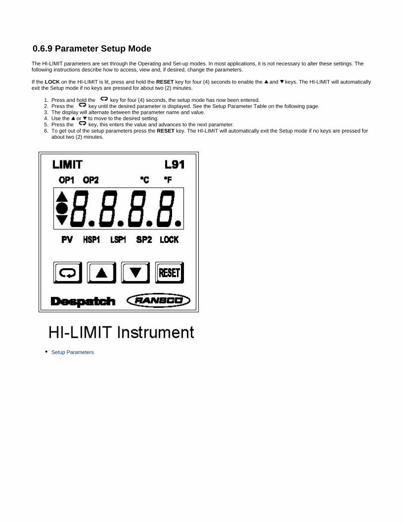
0.6.9 Parameter Setup Mode
The HI-LIMIT parameters are set through the Operating and Set-up modes. In most applications, it is not necessary to alter these settings. Thefollowing instructions describe how to access, view and, if desired, change the parameters.
If the on the HI-LIMIT is lit, press and hold the key for four (4) seconds to enable the and keys. The HI-LIMIT will automaticallyLOCK RESETexit the Setup mode if no keys are pressed for about two (2) minutes.
Press and hold the key for four (4) seconds, the setup mode has now been entered.Press the key until the desired parameter is displayed. See the Setup Parameter Table on the following page.The display will alternate between the parameter name and value.Use the or to move to the desired setting.Press the key, this enters the value and advances to the next parameter.To get out of the setup parameters press the key. The HI-LIMIT will automatically exit the Setup mode if no keys are pressed forRESETabout two (2) minutes.
Setup Parameters
Setup Parameters
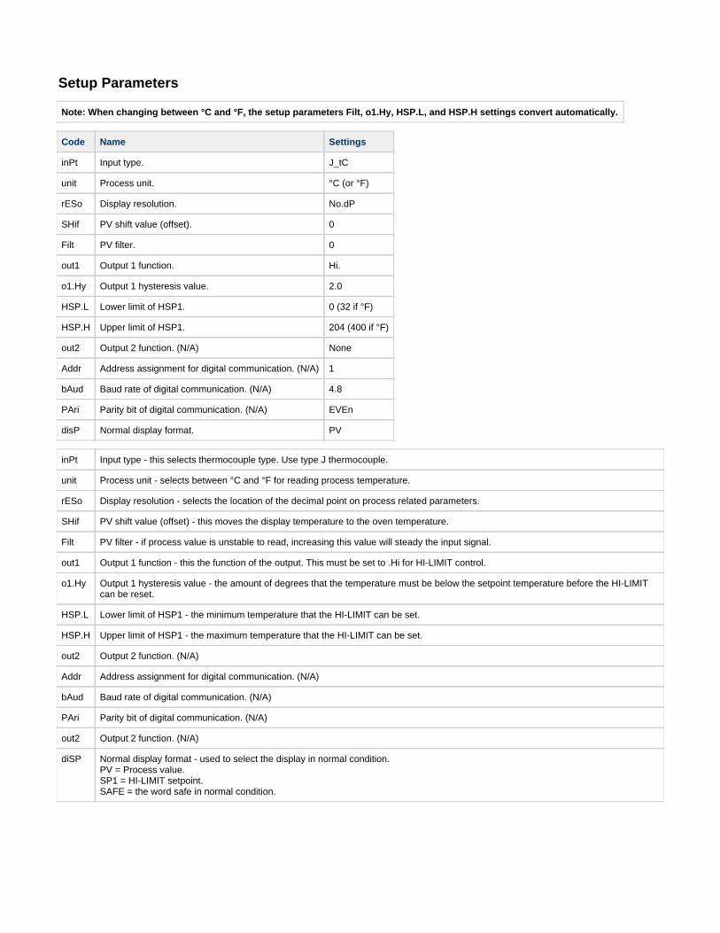
Note: When changing between °C and °F, the setup parameters Filt, o1.Hy, HSP.L, and HSP.H settings convert automatically.
Code Name Settings
inPt Input type. J_tC
unit Process unit. °C (or °F)
rESo Display resolution. No.dP
SHif PV shift value (offset). 0
Filt PV filter. 0
out1 Output 1 function. Hi.
o1.Hy Output 1 hysteresis value. 2.0
HSP.L Lower limit of HSP1. 0 (32 if °F)
HSP.H Upper limit of HSP1. 204 (400 if °F)
out2 Output 2 function. (N/A) None
Addr Address assignment for digital communication. (N/A) 1
bAud Baud rate of digital communication. (N/A) 4.8
PAri Parity bit of digital communication. (N/A) EVEn
disP Normal display format. PV
inPt Input type - this selects thermocouple type. Use type J thermocouple.
unit Process unit - selects between °C and °F for reading process temperature.
rESo Display resolution - selects the location of the decimal point on process related parameters.
SHif PV shift value (offset) - this moves the display temperature to the oven temperature.
Filt PV filter - if process value is unstable to read, increasing this value will steady the input signal.
out1 Output 1 function - this the function of the output. This must be set to .Hi for HI-LIMIT control.
o1.Hy Output 1 hysteresis value - the amount of degrees that the temperature must be below the setpoint temperature before the HI-LIMITcan be reset.
HSP.L Lower limit of HSP1 - the minimum temperature that the HI-LIMIT can be set.
HSP.H Upper limit of HSP1 - the maximum temperature that the HI-LIMIT can be set.
out2 Output 2 function. (N/A)
Addr Address assignment for digital communication. (N/A)
bAud Baud rate of digital communication. (N/A)
PAri Parity bit of digital communication. (N/A)
out2 Output 2 function. (N/A)
diSP Normal display format - used to select the display in normal condition. PV = Process value. SP1 = HI-LIMIT setpoint.SAFE = the word safe in normal condition.
1. 2.
3.
4.
5.
6.
7.
8. 9.
10. 11.
12. 13.
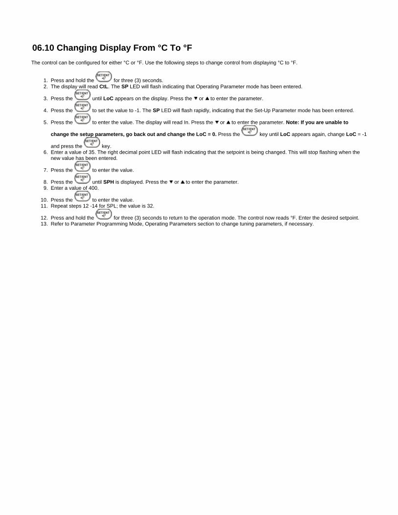
06.10 Changing Display From °C To °F
The control can be configured for either °C or °F. Use the following steps to change control from displaying °C to °F.
Press and hold the for three (3) seconds.The display will read . The LED will flash indicating that Operating Parameter mode has been entered.CtL SP
Press the until appears on the display. Press the or to enter the parameter.LoC
Press the to set the value to -1. The LED will flash rapidly, indicating that the Set-Up Parameter mode has been entered.SP
Press the to enter the value. The display will read In. Press the or to enter the parameter. Note: If you are unable to
Press the key until appears again, change = -1change the setup parameters, go back out and change the LoC = 0. LoC LoC
and press the key.Enter a value of 35. The right decimal point LED will flash indicating that the setpoint is being changed. This will stop flashing when thenew value has been entered.
Press the to enter the value.
Press the until is displayed. Press the or to enter the parameter.SPHEnter a value of 400.
Press the to enter the value.Repeat steps 12 -14 for SPL; the value is 32.
Press and hold the for three (3) seconds to return to the operation mode. The control now reads °F. Enter the desired setpoint.Refer to Parameter Programming Mode, Operating Parameters section to change tuning parameters, if necessary.
06.11 Removing Parts from the Finisher
After shutting down the Finisher, remove the parts from the chamber as follows:1. Wear gloves!2. Verify that the chamber is at room temperature on the TEMP CONTROL display, then open the chamber door.PV3. Use the tongs, remove each part. Lift each part up slightly and verify that it is not dripping before you remove it. If it is dripping, either:
leave it in on the shelf until it stops dripping.Wrap it (or re-wrap it) in absorbent cloth, then remove it.If any liquid support material drips on the oven chamber floor, liquify it with a hot air blower, then wipe it up.
DO NOT switch on the Finisher to liquify support material on the chamber floor. Hot liquid material can leak out the bottomdoor seal.
4. Check the level of support material in the tray. If it is half full, empty tray. Otherwise, the tray can become very heavy and difficult to empty.
06.12 Emptying the Tray
If the level is 2.5 cm (1 in) or less from the top of the tray, empty it as described below. check the level of support material in the tray:Always
Before you start a Finisher cycle.after you remove parts from the Finisher.
Do not allow the level of support material in the tray to get closer than 2.5cm (1 in) from the top rim of the tray. If the traygets too full, liquid support material could spill out and onto the floor of the chamber and leak out the bottom door seal.
1. Allow the Finisher to cool to room temperature, then open the chamber door.
Never open the chamber door when the Finisher is hot. Wait until it cools to room temperature as shown on the TEMPCONTROL's PV display. Opening the door when he Finisher is hot can damage the Finisher, cause severe burns, and starta fire.
2. Verify that all the support material in the tray is solid.
Never attempt to remove the tray if there is liquid support material in it. Wait until the support material in the tray is entirelysolid. Liquid support material can spill out of the tray as you are removing it. If it spills on your skin, it can burn you.
3. Remove the shelf from the top of the tray, lift the tray up and out of the tray bracket, then remove the tray from the oven chamber.4. Remove the block of solid support material from the tray.
NOTE: If the block of material is difficult to remove, place the tray in a freezer for several minutes, then try again.
5. Reinstall the empty tray in the oven chamber and place the shelf securely on top of it.
06.13 Finisher Shutdown
After parts have been in the finisher for the required amount of time, shut down the Finisher as described below before removing the parts fromthe finisher. Finisher cycle time will vary depending on your part geometry and the number of parts in the chamber.
WARNING: Never open the chamber door when the Finisher is hot. Wait until it cools to room temperature as shown on theTEMP CONTROL PV display. Opening the door when he Finisher is hot can damage the Finisher, cause severe burns, andstart a fire.
1. Turn the HEATER switch (on the Finisher control panel) OFF.2. Leave the POWER switch on and the chamber door closed until the Finisher chamber cools to room temperature. 3. When the TEMP CONTROL display shows room temperature, you can optionally turn off the POWER switch.PV
CAUTION: Do not turn off the POWER switch if the chamber temperature is above 100°C (212°F). Leaving POWER onenables you to view the actual chamber temperature on the TEMP CONTROL, and it keeps the fan running which prolongsthe life of the Finisher components.
0.6.1 Theory of Operation
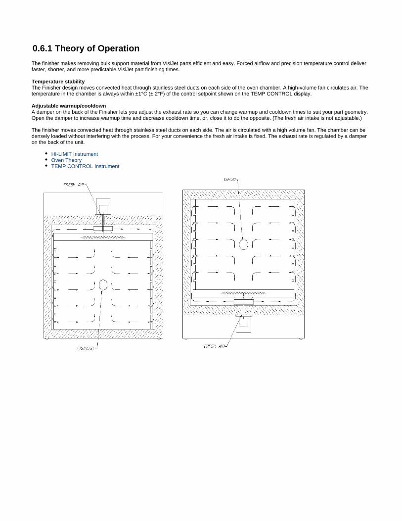
The finisher makes removing bulk support material from VisiJet parts efficient and easy. Forced airflow and precision temperature control deliverfaster, shorter, and more predictable VisiJet part finishing times.
Temperature stabilityThe Finisher design moves convected heat through stainless steel ducts on each side of the oven chamber. A high-volume fan circulates air. Thetemperature in the chamber is always within ±1°C (± 2°F) of the control setpoint shown on the TEMP CONTROL display.
Adjustable warmup/cooldownA damper on the back of the Finisher lets you adjust the exhaust rate so you can change warmup and cooldown times to suit your part geometry.Open the damper to increase warmup time and decrease cooldown time, or, close it to do the opposite. (The fresh air intake is not adjustable.)
The finisher moves convected heat through stainless steel ducts on each side. The air is circulated with a high volume fan. The chamber can bedensely loaded without interfering with the process. For your convenience the fresh air intake is fixed. The exhaust rate is regulated by a damperon the back of the unit.
HI-LIMIT InstrumentOven TheoryTEMP CONTROL Instrument

Oven Theory
The oven has an efficient forced circulating oven to 204°C (400°F). A forced circulating oven relies on a circulating motor to move air through thechamber, which is much more efficient and uniform than a gravity convected oven. In addition, it takes a finite amount of time for the oven to soakin at the desired setpoint. The time that it takes the unit to soak in at setpoint is related to such parameters as chamber area, load mass and theability to absorb heat and exhaust rate. The oven uses an indicating microprocessor based digital control that displays the actual chambertemperature at the sensing point. The CONTROL's temperature sensor optimizes the control action for the entire chamber for various loadconditions. The CONTROL display may fluctuate a few degrees around the setpoint, but the overall chamber temperature will remain very stable.The underlying reason for this is that the display is showing temperature fluctuations at the temperature sensor location, not the overall chambertemperature. The strategic location of the sensor compensates for delays in heat convection and enhances the performance and temperaturecontrol of the oven.
HI-LIMIT Instrument
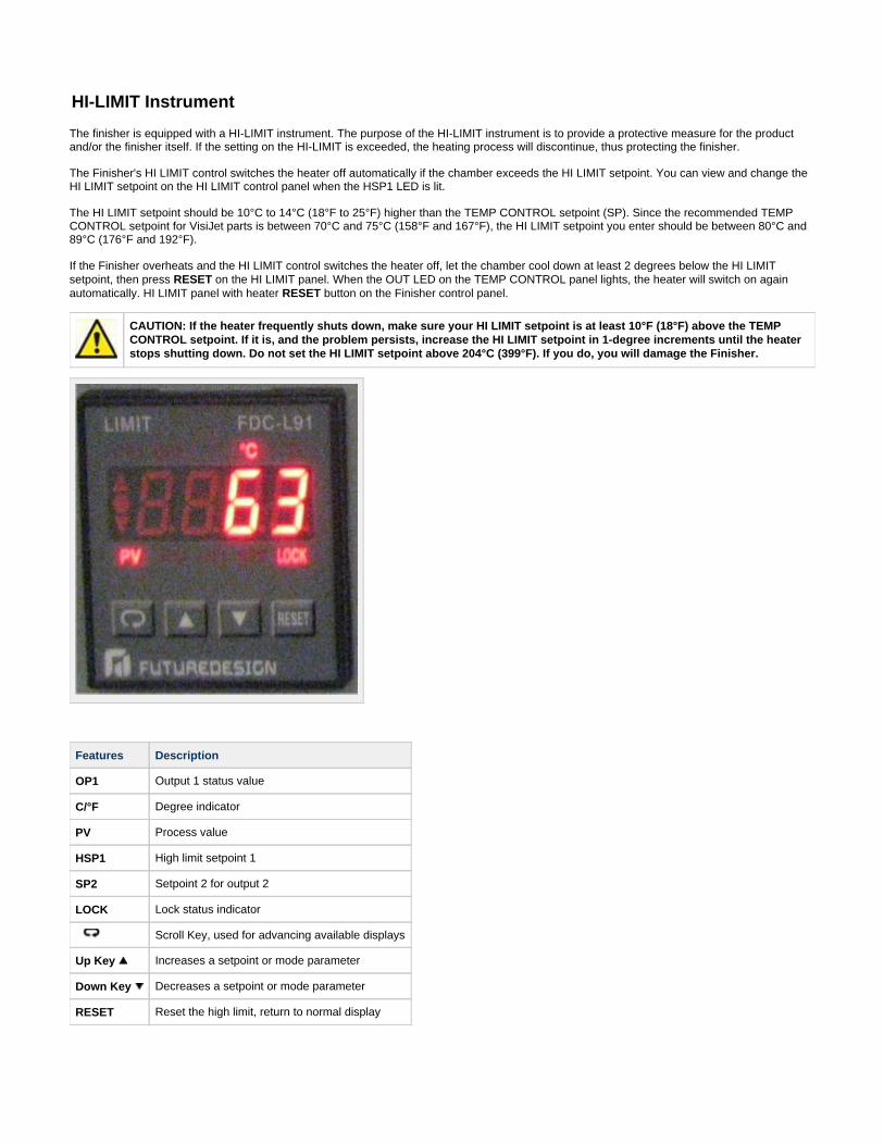
The finisher is equipped with a HI-LIMIT instrument. The purpose of the HI-LIMIT instrument is to provide a protective measure for the productand/or the finisher itself. If the setting on the HI-LIMIT is exceeded, the heating process will discontinue, thus protecting the finisher.
The Finisher's HI LIMIT control switches the heater off automatically if the chamber exceeds the HI LIMIT setpoint. You can view and change theHI LIMIT setpoint on the HI LIMIT control panel when the HSP1 LED is lit.
The HI LIMIT setpoint should be 10°C to 14°C (18°F to 25°F) higher than the TEMP CONTROL setpoint (SP). Since the recommended TEMPCONTROL setpoint for VisiJet parts is between 70°C and 75°C (158°F and 167°F), the HI LIMIT setpoint you enter should be between 80°C and89°C (176°F and 192°F).
If the Finisher overheats and the HI LIMIT control switches the heater off, let the chamber cool down at least 2 degrees below the HI LIMITsetpoint, then press on the HI LIMIT panel. When the OUT LED on the TEMP CONTROL panel lights, the heater will switch on againRESETautomatically. HI LIMIT panel with heater button on the Finisher control panel.RESET
CAUTION: If the heater frequently shuts down, make sure your HI LIMIT setpoint is at least 10°F (18°F) above the TEMPCONTROL setpoint. If it is, and the problem persists, increase the HI LIMIT setpoint in 1-degree increments until the heaterstops shutting down. Do not set the HI LIMIT setpoint above 204°C (399°F). If you do, you will damage the Finisher.
Features Description
OP1 Output 1 status value
C/°F Degree indicator
PV Process value
HSP1 High limit setpoint 1
SP2 Setpoint 2 for output 2
LOCK Lock status indicator
Scroll Key, used for advancing available displays
Up Key Increases a setpoint or mode parameter
Down Key Decreases a setpoint or mode parameter
RESET Reset the high limit, return to normal display
TEMP CONTROL Instrument
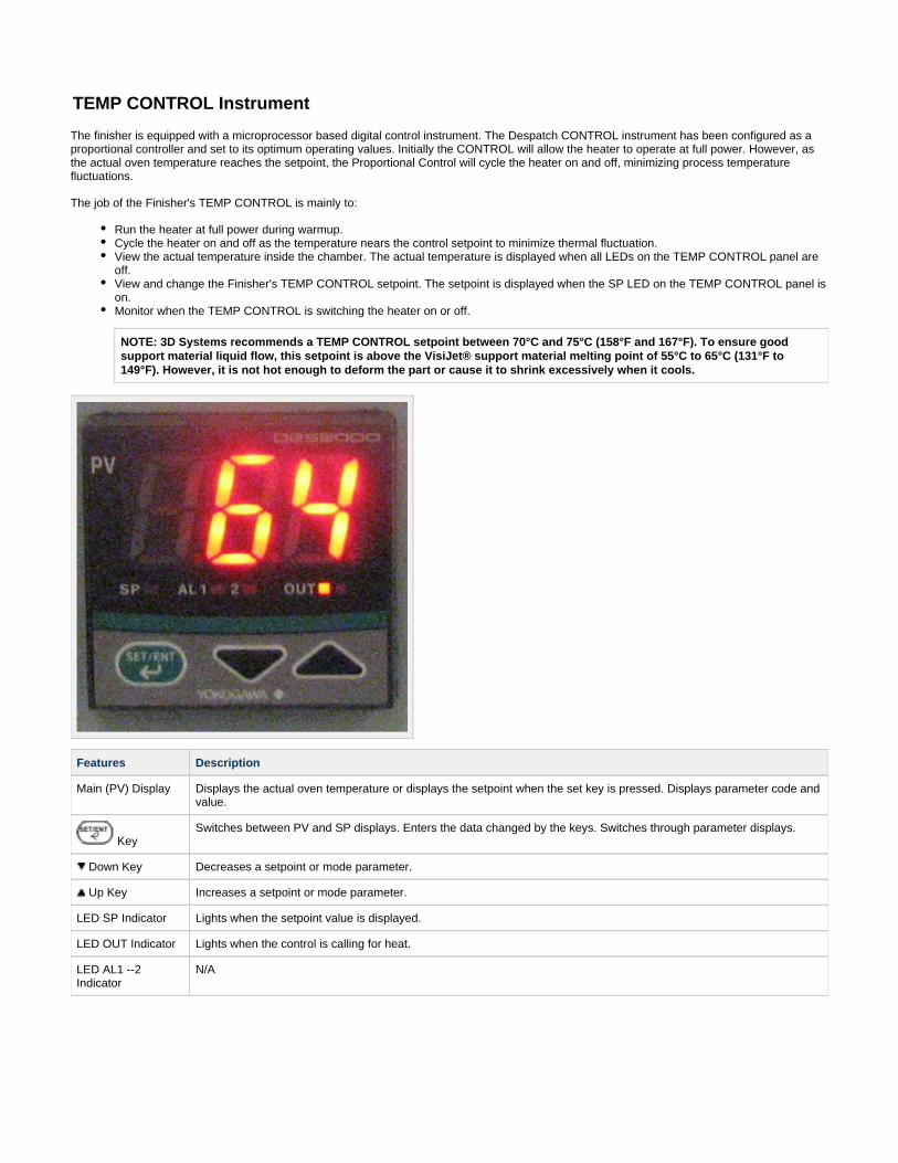
The finisher is equipped with a microprocessor based digital control instrument. The Despatch CONTROL instrument has been configured as aproportional controller and set to its optimum operating values. Initially the CONTROL will allow the heater to operate at full power. However, asthe actual oven temperature reaches the setpoint, the Proportional Control will cycle the heater on and off, minimizing process temperaturefluctuations.
The job of the Finisher's TEMP CONTROL is mainly to:
Run the heater at full power during warmup.Cycle the heater on and off as the temperature nears the control setpoint to minimize thermal fluctuation.View the actual temperature inside the chamber. The actual temperature is displayed when all LEDs on the TEMP CONTROL panel areoff.View and change the Finisher's TEMP CONTROL setpoint. The setpoint is displayed when the SP LED on the TEMP CONTROL panel ison.Monitor when the TEMP CONTROL is switching the heater on or off.
NOTE: 3D Systems recommends a TEMP CONTROL setpoint between 70°C and 75°C (158°F and 167°F). To ensure goodsupport material liquid flow, this setpoint is above the VisiJet® support material melting point of 55°C to 65°C (131°F to149°F). However, it is not hot enough to deform the part or cause it to shrink excessively when it cools.
Features Description
Main (PV) Display Displays the actual oven temperature or displays the setpoint when the set key is pressed. Displays parameter code andvalue.
KeySwitches between PV and SP displays. Enters the data changed by the keys. Switches through parameter displays.
Down Key Decreases a setpoint or mode parameter.
Up Key Increases a setpoint or mode parameter.
LED SP Indicator Lights when the setpoint value is displayed.
LED OUT Indicator Lights when the control is calling for heat.
LED AL1 --2Indicator
N/A
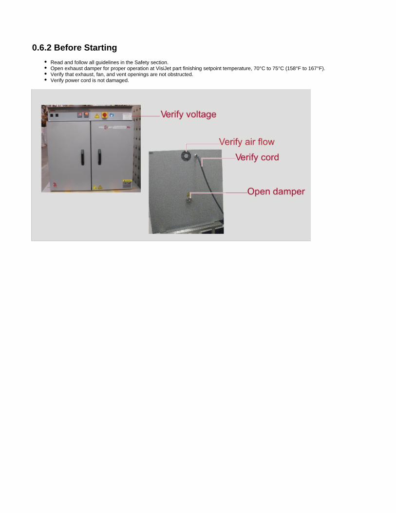
0.6.2 Before Starting
Read and follow all guidelines in the Safety section.Open exhaust damper for proper operation at VisiJet part finishing setpoint temperature, 70°C to 75°C (158°F to 167°F).Verify that exhaust, fan, and vent openings are not obstructed.Verify power cord is not damaged.
Pre-Startup Checklist
Know the system. Read instructions in this guide to gain a full understanding of safe, continuous, satisfactory, trouble-free operation.
Check line voltage. Voltage must correspond to nameplate requirements of motors and controls. Refer to the section on powerrequirements in of this guide.0.3.1 ProJet™ XL Finisher Physical SpecificationFresh air, exhaust, and electrical cabinet openings. Do not be careless about restrictions in and around the fresh air and exhaustopenings. Under no condition permit them to become so filled with dirt that they appreciably reduce the air quantity. Refer to the Set-up
in this guide.instructionsVentilation. There is an exhaust opening in the rear of the unit. The exhaust vent may have to be closed to reach the maximumtemperature of 204°C, especially if operating on 208 volts. They may need to be opened to operate properly at the lower range of theoven's design.
Helpful hints
For drying ovens, open vent to prevent buildup of moisture.or sample heating, close the vent when no ventilation is required.
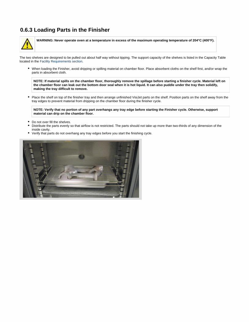
0.6.3 Loading Parts in the Finisher
WARNING: Never operate oven at a temperature in excess of the maximum operating temperature of 204°C (400°F).
The two shelves are designed to be pulled out about half way without tipping. The support capacity of the shelves is listed in the Capacity Tablelocated in the .Facility Requirements section
When loading the Finisher, avoid dripping or spilling material on chamber floor. Place absorbent cloths on the shelf first, and/or wrap theparts in absorbent cloth.
NOTE: If material spills on the chamber floor, thoroughly remove the spillage before starting a finisher cycle. Material left onthe chamber floor can leak out the bottom door seal when it is hot liquid. It can also puddle under the tray then solidify,making the tray difficult to remove.
Place the shelf on top of the finisher tray and then arrange unfinished VisiJet parts on the shelf. Position parts on the shelf away from thetray edges to prevent material from dripping on the chamber floor during the finisher cycle.
NOTE: Verify that no portion of any part overhangs any tray edge before starting the Finisher cycle. Otherwise, supportmaterial can drip on the chamber floor.
Do not over fill the shelves.Distribute the parts evenly so that airflow is not restricted. The parts should not take up more than two-thirds of any dimension of theinside cavity.Verify that parts do not overhang any tray edges before you start the finishing cycle.
1. a.
2. a. b.
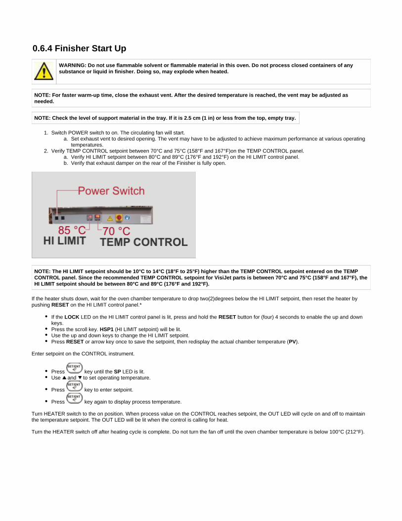
0.6.4 Finisher Start Up
WARNING: Do not use flammable solvent or flammable material in this oven. Do not process closed containers of anysubstance or liquid in finisher. Doing so, may explode when heated.
NOTE: For faster warm-up time, close the exhaust vent. After the desired temperature is reached, the vent may be adjusted asneeded.
NOTE: Check the level of support material in the tray. If it is 2.5 cm (1 in) or less from the top, empty tray.
Switch POWER switch to on. The circulating fan will start.Set exhaust vent to desired opening. The vent may have to be adjusted to achieve maximum performance at various operatingtemperatures.
Verify TEMP CONTROL setpoint between 70°C and 75°C (158°F and 167°F)on the TEMP CONTROL panel.Verify HI LIMIT setpoint between 80°C and 89°C (176°F and 192°F) on the HI LIMIT control panel.Verify that exhaust damper on the rear of the Finisher is fully open.
NOTE: The HI LIMIT setpoint should be 10°C to 14°C (18°F to 25°F) higher than the TEMP CONTROL setpoint entered on the TEMPCONTROL panel. Since the recommended TEMP CONTROL setpoint for VisiJet parts is between 70°C and 75°C (158°F and 167°F), theHI LIMIT setpoint should be between 80°C and 89°C (176°F and 192°F).
If the heater shuts down, wait for the oven chamber temperature to drop two(2)degrees below the HI LIMIT setpoint, then reset the heater bypushing on the HI LIMIT control panel.*RESET
If the LED on the HI LIMIT control panel is lit, press and hold the button for (four) 4 seconds to enable the up and downLOCK RESETkeys.Press the scroll key. (HI LIMIT setpoint) will be lit.HSP1Use the up and down keys to change the HI LIMIT setpoint.Press or arrow key once to save the setpoint, then redisplay the actual chamber temperature ( ).RESET PV
Enter setpoint on the CONTROL instrument.
Press key until the LED is lit.SPUse and to set operating temperature.
Press key to enter setpoint.
Press key again to display process temperature.
Turn HEATER switch to the on position. When process value on the CONTROL reaches setpoint, the OUT LED will cycle on and off to maintainthe temperature setpoint. The OUT LED will be lit when the control is calling for heat.
Turn the HEATER switch off after heating cycle is complete. Do not turn the fan off until the oven chamber temperature is below 100°C (212°F).

0.7 MaintenanceThis section describes how to maintain your ProJet Finisher XL to help ensure longer life and trouble-free operation.
0.7.1 Checklist07.2 Testing07.3 How to Replace the TEMP Control07.4 How to Replace the HILIMIT Control07.5 How to Replace the Heater07.6 How to Replace the Fan Motor07.7 Replacement Parts
1.
2. 3. 4. 5. 6. 7. 8. 9.
10. 11.
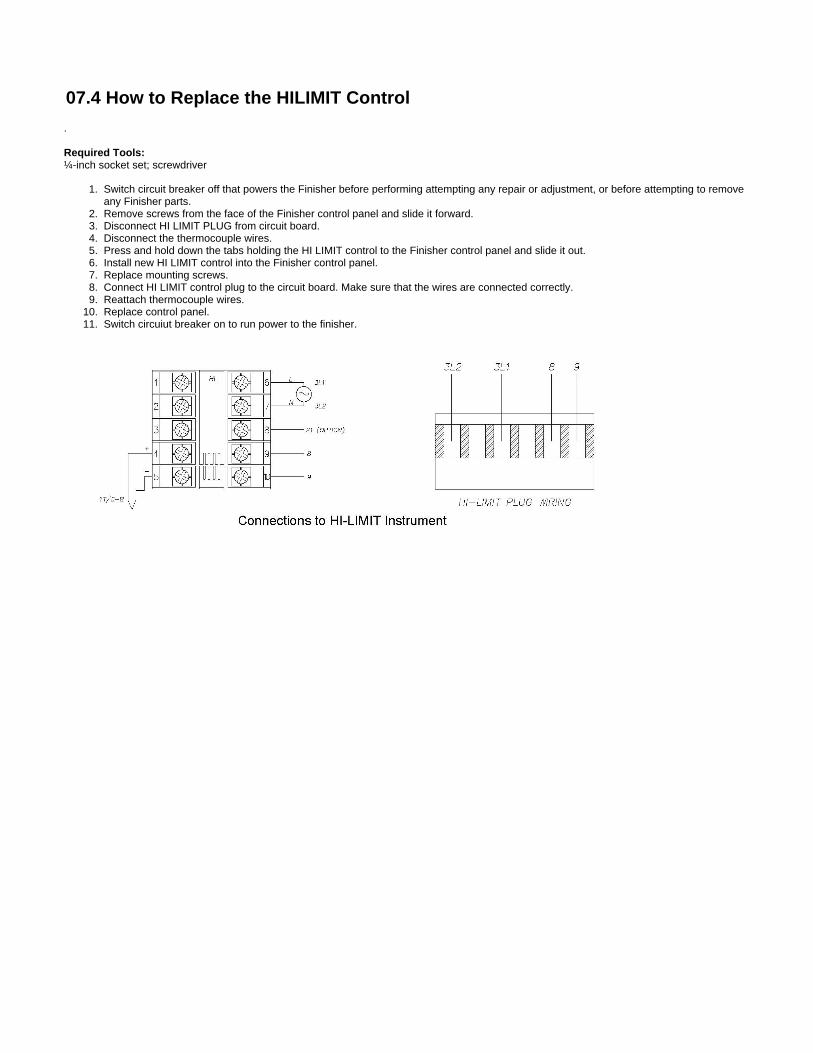
07.4 How to Replace the HILIMIT Control
.
Required Tools:¼-inch socket set; screwdriver
Switch circuit breaker off that powers the Finisher before performing attempting any repair or adjustment, or before attempting to removeany Finisher parts.Remove screws from the face of the Finisher control panel and slide it forward.Disconnect HI LIMIT PLUG from circuit board.Disconnect the thermocouple wires.Press and hold down the tabs holding the HI LIMIT control to the Finisher control panel and slide it out.Install new HI LIMIT control into the Finisher control panel.Replace mounting screws.Connect HI LIMIT control plug to the circuit board. Make sure that the wires are connected correctly.Reattach thermocouple wires.Replace control panel.Switch circuiut breaker on to run power to the finisher.
1.
2. 3.
a. b.
4. a. b.
5. 6. 7. 8. 9.
10. 11. 12. 13.
07.5 How to Replace the Heater
Required Tools:
3/8" wrenchPhilips screwdriver¼-inch socket set
Switch circuit breaker off that powers the Finisher before performing attempting any repair or adjustment, or before attempting to removeany Finisher parts.Remove shelves.Remove side ducts (left and right).
Remove screws from each duct.Remove duct from oven.
Remove heater cover.Remove screws from the heater cover.Remove heater cover from the oven.
Disconnect heater leads from heater element with wrench. Note which wires go on which terminals.Remove screws holding the heater frame to the oven body.Remove heater and discard.Install new heater frame to oven body.Attach heater leads to appropriate terminals.Replace heater cover.Replace side ducts.Replace shelves.Switch circuit breaker on to run power to the finisher.
1.
2. 3.
a. b.
4. a. b.
5.
6. 7.
a. b. c.
8.
9. 10. 11.
a. b.
12. 13. 14.
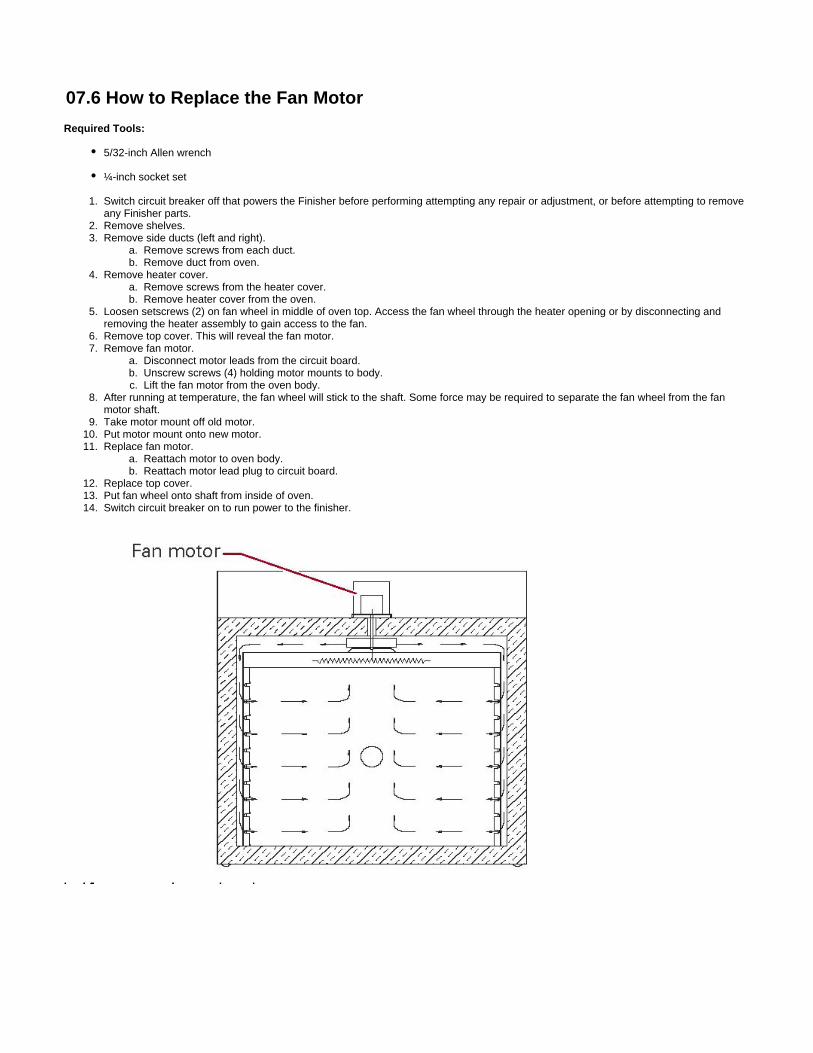
07.6 How to Replace the Fan Motor
Required Tools:
5/32-inch Allen wrench
¼-inch socket set
Switch circuit breaker off that powers the Finisher before performing attempting any repair or adjustment, or before attempting to removeany Finisher parts.Remove shelves.Remove side ducts (left and right).
Remove screws from each duct.Remove duct from oven.
Remove heater cover.Remove screws from the heater cover.Remove heater cover from the oven.
Loosen setscrews (2) on fan wheel in middle of oven top. Access the fan wheel through the heater opening or by disconnecting andremoving the heater assembly to gain access to the fan.Remove top cover. This will reveal the fan motor.Remove fan motor.
Disconnect motor leads from the circuit board.Unscrew screws (4) holding motor mounts to body.Lift the fan motor from the oven body.
After running at temperature, the fan wheel will stick to the shaft. Some force may be required to separate the fan wheel from the fanmotor shaft.Take motor mount off old motor.Put motor mount onto new motor.Replace fan motor.
Reattach motor to oven body.Reattach motor lead plug to circuit board.
Replace top cover.Put fan wheel onto shaft from inside of oven.Switch circuit breaker on to run power to the finisher.

07.7 Replacement Parts
To order or return parts, contact . When returning parts, our customer service representative will provide you with3D Systems Customer Supportan RMA (Return Material Authorization) number. The RMA number must be attached to the returned part for identification. When you are orderingparts, be sure to give the model number, serial number and the part number. This will expedite the process of obtaining a replacement part.
1.
2. 3. 4. 5. 6. 7. 8. 9.
10.
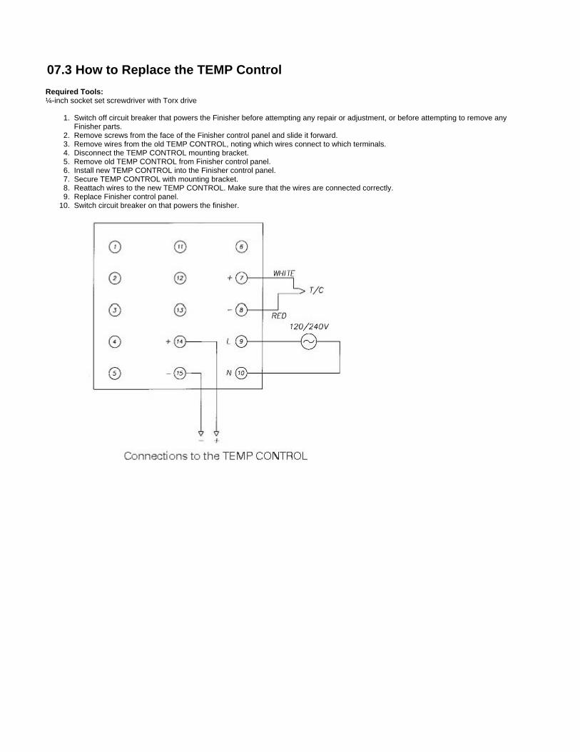
07.3 How to Replace the TEMP Control
Required Tools:¼-inch socket set screwdriver with Torx drive
Switch off circuit breaker that powers the Finisher before attempting any repair or adjustment, or before attempting to remove anyFinisher parts.Remove screws from the face of the Finisher control panel and slide it forward.Remove wires from the old TEMP CONTROL, noting which wires connect to which terminals.Disconnect the TEMP CONTROL mounting bracket.Remove old TEMP CONTROL from Finisher control panel.Install new TEMP CONTROL into the Finisher control panel.Secure TEMP CONTROL with mounting bracket.Reattach wires to the new TEMP CONTROL. Make sure that the wires are connected correctly.Replace Finisher control panel.Switch circuit breaker on that powers the finisher.
0.7.1 Checklist
Keep equipment clean. Gradual dirt accumulation retards airflow. A dirty Finisher can result in unsatisfactory operation such as unbalancedtemperature in the work chamber, reduced heating capacity, reduced production, overheated components, etc. Keep the walls, floor and ceiling ofthe oven chamber free of dirt and dust. Floating dust or accumulated dirt may produce unsatisfactory work results. Keep all equipment accessible.Do not permit other materials to be stored or piled against it.
Prevent overflows and spills in the oven chamber. Check the support material liquid level in the tray before and after every finishing cycle.Empty the tray if the liquid level is 2.5 cm (1 in) or less from the top.
Protect controls against excessive heat. This is particularly true of controls, motors or other equipment containing electronic components.Avoid ambient temperatures above 51.5°C (125°F).
Establish maintenance and checkup schedules. Do this promptly and follow the schedules faithfully. Careful operation and maintenance willbe more than paid for in continuous, safe and economical operation.
Maintain equipment in good repair. Make repairs immediately. Delays may be costly in added expense for labor and materials and in prolongedshut down.
Practice safety. Always know what you are doing before you do it. Make CAUTION, PATIENCE, and GOOD JUDGMENT the safety watchwordsfor the operation of your Finisher.
Lubrication. All door latches, hinges, door operating mechanisms, bearing or wear surfaces should be lubricated to ensure easy operation.
07.2 Testing
Warning: Failure to heed warnings in this manual and on the Finisher could result in death, personal injury or propertydamage.
Warning: Switch off power circuit breaker to the Finisher before performing attempting any repair or adjustment.
Testing should be performed carefully and regularly. The safety of personnel as well as the condition of equipment may depend upon the properoperation of any one of the functions of these controls. Test the TEMP CONTROL every 40 hours. Check that the TEMP CONTROL OUT LED iscycling on and off. Also, verify that the heater is working.
Test the HI LIMIT control every 40 hours as follows: With the Finisher operating at a given temperature, set the HILIMIT setpoint down to thecontrol setpoint. The HI LIMIT control has tripped when OP1 is lit. Push RESET after adjusting the HI LIMIT setpoint back to a higher setting, orletting the oven chamber temperature drop 2 (two) degrees below the HI LIMIT setpoint.
NOTE: Two (2) degrees is the factory setting for the HILIMIT control's hysteresis parameter. It can be changed. See the descriptionfor the Output 1 Hysteresis Value parameter, o1.Hy, in "HI LIMIT Control Parameters."
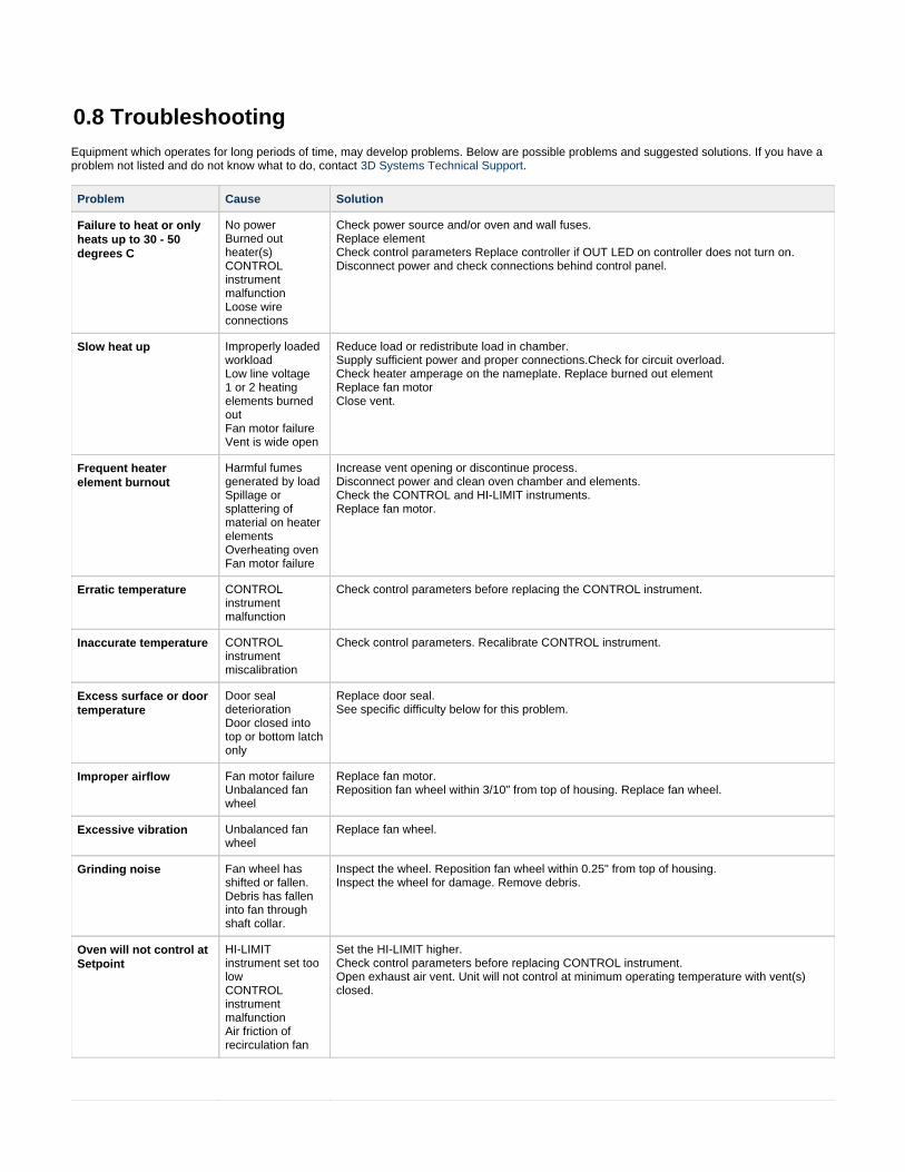
0.8 TroubleshootingEquipment which operates for long periods of time, may develop problems. Below are possible problems and suggested solutions. If you have aproblem not listed and do not know what to do, contact .3D Systems Technical Support
Problem Cause Solution
Failure to heat or onlyheats up to 30 - 50degrees C
No powerBurned outheater(s)CONTROLinstrumentmalfunctionLoose wireconnections
Check power source and/or oven and wall fuses.Replace elementCheck control parameters Replace controller if OUT LED on controller does not turn on.Disconnect power and check connections behind control panel.
Slow heat up Improperly loadedworkloadLow line voltage 1 or 2 heatingelements burnedoutFan motor failureVent is wide open
Reduce load or redistribute load in chamber.Supply sufficient power and proper connections.Check for circuit overload.Check heater amperage on the nameplate. Replace burned out elementReplace fan motorClose vent.
Frequent heaterelement burnout
Harmful fumesgenerated by loadSpillage orsplattering ofmaterial on heaterelements Overheating oven Fan motor failure
Increase vent opening or discontinue process.Disconnect power and clean oven chamber and elements.Check the CONTROL and HI-LIMIT instruments.Replace fan motor.
Erratic temperature CONTROLinstrumentmalfunction
Check control parameters before replacing the CONTROL instrument.
Inaccurate temperature CONTROLinstrumentmiscalibration
Check control parameters. Recalibrate CONTROL instrument.
Excess surface or doortemperature
Door sealdeteriorationDoor closed intotop or bottom latchonly
Replace door seal.See specific difficulty below for this problem.
Improper airflow Fan motor failureUnbalanced fanwheel
Replace fan motor.Reposition fan wheel within 3/10" from top of housing. Replace fan wheel.
Excessive vibration Unbalanced fanwheel
Replace fan wheel.
Grinding noise Fan wheel hasshifted or fallen.Debris has falleninto fan throughshaft collar.
Inspect the wheel. Reposition fan wheel within 0.25" from top of housing.Inspect the wheel for damage. Remove debris.
Oven will not control atSetpoint
HI-LIMITinstrument set toolowCONTROLinstrumentmalfunctionAir friction ofrecirculation fan
Set the HI-LIMIT higher.Check control parameters before replacing CONTROL instrument.Open exhaust air vent. Unit will not control at minimum operating temperature with vent(s)closed.

Heater does notshutdown until temp.reaches the HI-LIMITsetting
CONTROLinstrumentmalfunctionSSR Relaymalfunction
Verify control parameters. Replace relay if no output exists. Replace CONTROL instrument if5VDC output exists.Replace relay if no CONTROL output exists.
*Door closes into top orbottom latch only.
Uneven latchtensionadjustment
Ensure that latch strike is contacting center of latch. Adjust mounting angle as required.Adjust door for even top and bottom latch tension by turning screws on ends of latch.Clockwise increases tension on latch. Counterclockwise decreases tension.
Door will not stayclosed
Inadequate latchtension
Ensure that latch strike is contacting center of latch. Adjust mounting angle to center asrequired. Increase latch tension by turning screws on end of latch clockwise. Adjust in evenincrements on all four screws to keep door pull even.
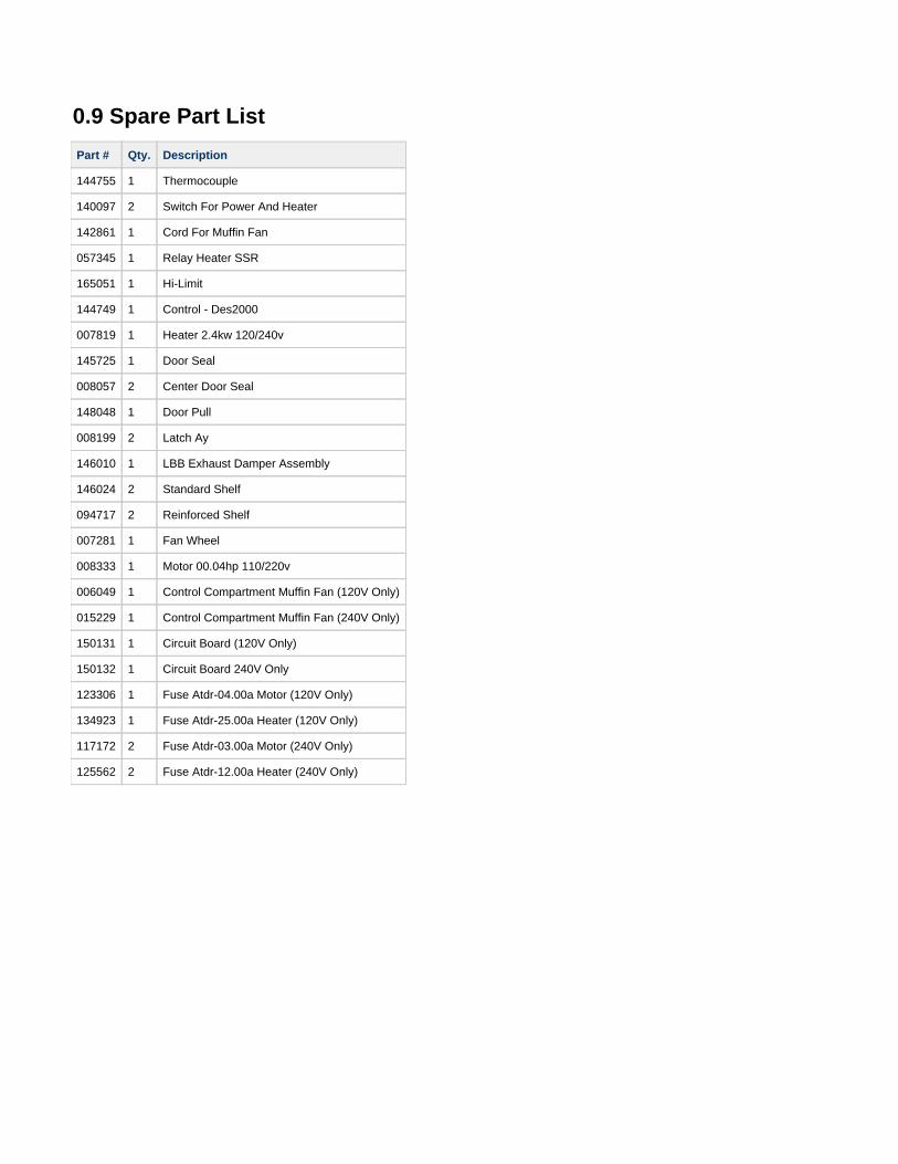
0.9 Spare Part List
Part # Qty. Description
144755 1 Thermocouple
140097 2 Switch For Power And Heater
142861 1 Cord For Muffin Fan
057345 1 Relay Heater SSR
165051 1 Hi-Limit
144749 1 Control - Des2000
007819 1 Heater 2.4kw 120/240v
145725 1 Door Seal
008057 2 Center Door Seal
148048 1 Door Pull
008199 2 Latch Ay
146010 1 LBB Exhaust Damper Assembly
146024 2 Standard Shelf
094717 2 Reinforced Shelf
007281 1 Fan Wheel
008333 1 Motor 00.04hp 110/220v
006049 1 Control Compartment Muffin Fan (120V Only)
015229 1 Control Compartment Muffin Fan (240V Only)
150131 1 Circuit Board (120V Only)
150132 1 Circuit Board 240V Only
123306 1 Fuse Atdr-04.00a Motor (120V Only)
134923 1 Fuse Atdr-25.00a Heater (120V Only)
117172 2 Fuse Atdr-03.00a Motor (240V Only)
125562 2 Fuse Atdr-12.00a Heater (240V Only)