Embed Size (px)
Citation preview
System Description Structure
Product Manual IRB 1400 3
1 Structure
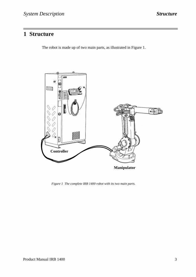
The robot is made up of two main parts, as illustrated in Figure 1.
Figure 1 The complete IRB 1400 robot with its two main parts.
Manipulator
Controller
Structure System Description
4 Product Manual IRB 1400
1.1 Manipulator
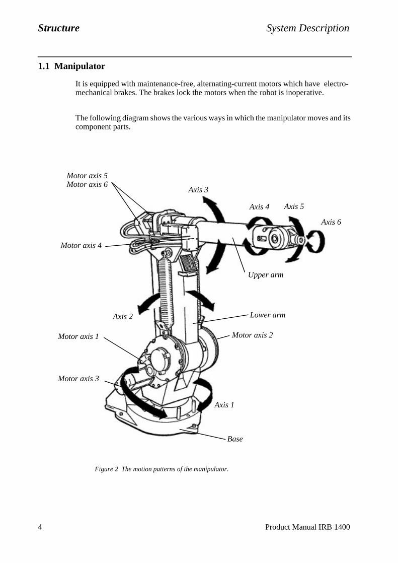
It is equipped with maintenance-free, alternating-current motors which have electro-mechanical brakes. The brakes lock the motors when the robot is inoperative.
The following diagram shows the various ways in which the manipulator moves and its component parts.
Figure 2 The motion patterns of the manipulator.
Motor axis 5Motor axis 6
Motor axis 4
Axis 2
Axis 1
Motor axis 1
Axis 3
Motor axis 2
Motor axis 3
Axis 4 Axis 5
Axis 6
Upper arm
Lower arm
Base
System Description Structure
Product Manual IRB 1400 5
1.2 Controller
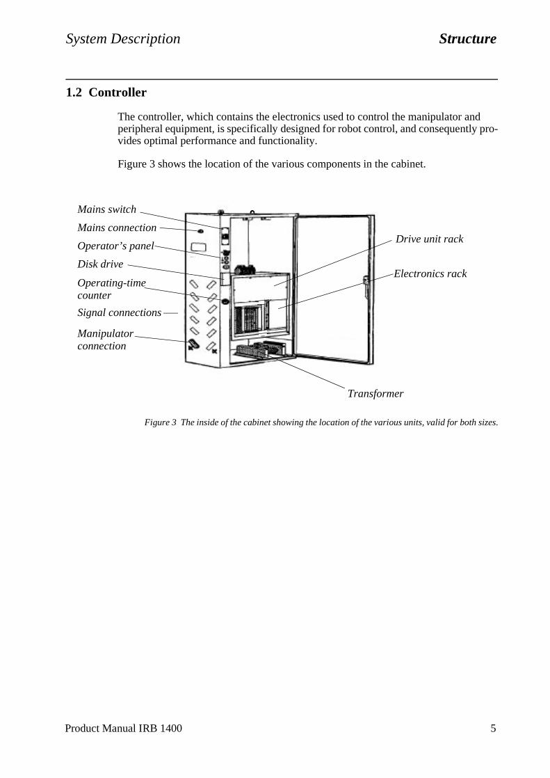
The controller, which contains the electronics used to control the manipulator and peripheral equipment, is specifically designed for robot control, and consequently pro-vides optimal performance and functionality.
Figure 3 shows the location of the various components in the cabinet.
Figure 3 The inside of the cabinet showing the location of the various units, valid for both sizes.
Mains switch
Mains connection
Disk drive
Signal connections
Manipulator
Operator’s panelDrive unit rack
Operating-time Electronics rack
counter
connection
Transformer
Structure System Description
6 Product Manual IRB 1400
1.3 Electronics unit
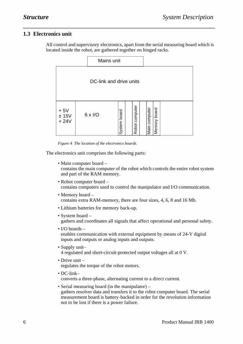
All control and supervisory electronics, apart from the serial measuring board which is located inside the robot, are gathered together on hinged racks.
Figure 4 The location of the electronics boards.
The electronics unit comprises the following parts:
• Main computer board –contains the main computer of the robot which controls the entire robot system and part of the RAM memory.
• Robot computer board –contains computers used to control the manipulator and I/O communication.
• Memory board –contains extra RAM-memory, there are four sizes, 4, 6, 8 and 16 Mb.
• Lithium batteries for memory back-up.
• System board – gathers and coordinates all signals that affect operational and personal safety.
• I/O boards –enables communication with external equipment by means of 24-V digital inputs and outputs or analog inputs and outputs.
• Supply unit–4 regulated and short-circuit-protected output voltages all at 0 V.
• Drive unit –regulates the torque of the robot motors.
• DC-link–converts a three-phase, alternating current to a direct current.
• Serial measuring board (in the manipulator) –gathers resolver data and transfers it to the robot computer board. The serial measurement board is battery-backed in order for the revolution information not to be lost if there is a power failure.
Mains unit
DC-link and drive units
6 x I/OS
yste
m b
oard+ 5V
± 15V+ 24V
Rob
ot c
ompu
ter
Mai
n co
mpu
ter
Mem
ory
boar
d
System Description Computer System
Product Manual IRB 1400 7
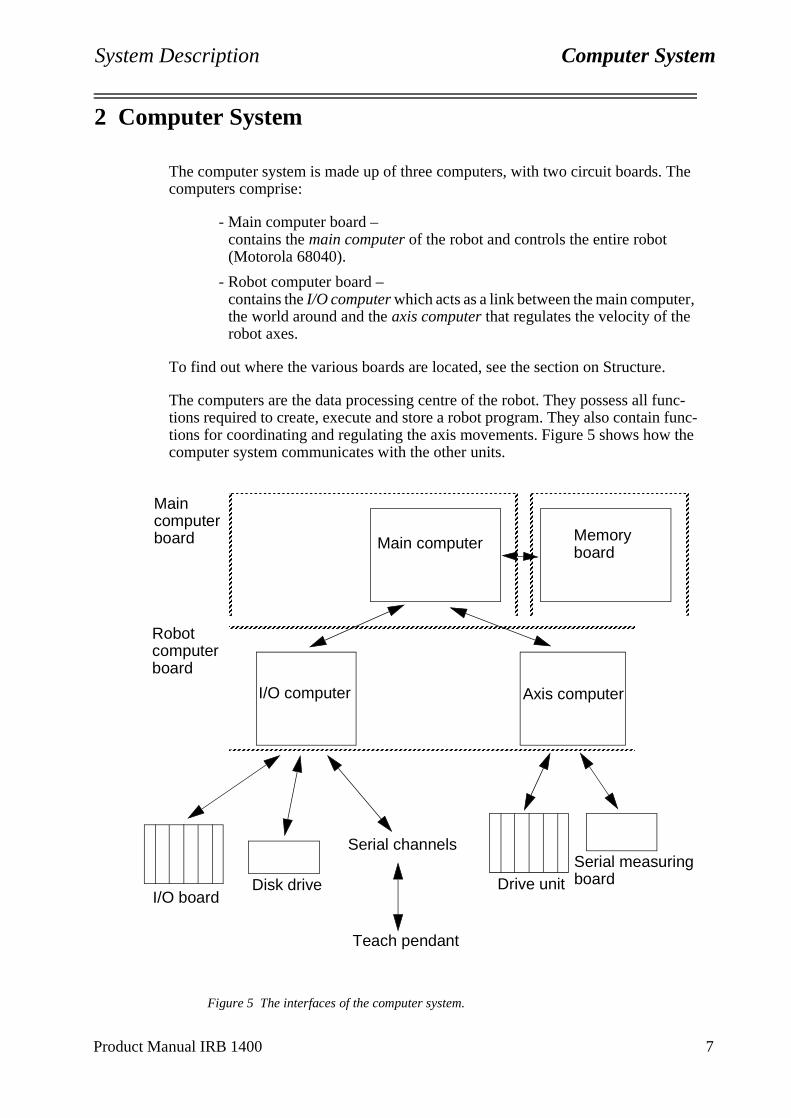
2 Computer System
The computer system is made up of three computers, with two circuit boards. The computers comprise:
- Main computer board –contains the main computer of the robot and controls the entire robot (Motorola 68040).
- Robot computer board –contains the I/O computer which acts as a link between the main computer, the world around and the axis computer that regulates the velocity of the robot axes.
To find out where the various boards are located, see the section on Structure.
The computers are the data processing centre of the robot. They possess all func-tions required to create, execute and store a robot program. They also contain func-tions for coordinating and regulating the axis movements. Figure 5 shows how the computer system communicates with the other units.
Figure 5 The interfaces of the computer system.
AAAAAAAA
AAAAAAAA
AAAAAAAA
AAAAAAAA
AAAAAAAA
AAAAAAAA
AAAAAAAA
AAAAAAAA
AAAAAAAA
AAAAAAAA
AAAAAAAA
AAAAAAAA
AAAAAAAA
AAAAAAAA
AAAAAAAA
AAAAAAAA
AAAAAAAA
AAAAAAAA
AAAAAAAA
AAAAAAAA
AAAAAAAA
AAAAAAAA
AAAAAAAA
AAAAAAAA
AAAAAAAA
AAAAAAAA
AAAAAAAA
AAAAAAAA
AAAA
AAAAAAAAAAAAAAAAAAAAAAAAAAAAAAAAAAAAAAAAAAAAAAAAAAAAAAAAAAAAAAAAAAAAAAAAAAAAAAAAAAAAAAAAAAAAAAAAAAAA
AAAAAAAA
AAAAAAAA
AAAAAAAA
AAAAAAAA
AAAAAAAA
AAAAAAAA
AAAAAAAA
AAAAAAAA
AAAAAAAA
AAAAAAAA
AAAAAAAA
AAAAAAAA
AAAAAAAA
AAAAAAAA
AAAAAAAA
AAAAAAAA
AAAAAAAA
AAAAAAAA
AAAAAAAA
AAAAAAAA
AAAAAAAA
AAAAAAAA
AAAAAAAA
AAAAAAAA
AAAAAAAA
AAAAAAAA
AAAAAAAA
AAAAAAAA
AA
AAAAAAAAAAAAAAAAAAAAAAAAAAAAAAAAAAAAAAAAAAAAAAAAAAAAAAAAAAAAAAAAAAAAAAAAAAAAAAAAAAAAAAAAAAAAAAAAAAAA
AAAAAAAAAAAAAAAAAAAAAAAAAAAAAAAAAAAAAAAAAAAAAAAAAAAAAAAAAAAAAAAAAAAAAAAAAAAAAAAAAAAAAAAAAAAAAAAAAAAAAAAAAAAAAAAAAAAAAAAAAAAAAAAAAAAAAAAAAAAAAAAAAAAAAAAAAAAAAAAA
AAAAAAAAAAAAAAAAAAAAAAAAAAAAAAAAAAAAAAAAAAAAAAAAA
AAAAAAAAAAAAAAAAAAAAAAAAAAAAAAAAAAAAAAAAAAAAAAAAAAAAAAAAAAAAAAAAAAAAAAAAAAAAAAAAAAAAAAAAAAAAAAAAAAAAAAAAAAAAAAAAAAAAAAAAAAAAAAAAAAAAAAAAAAAAAAAAAAAAAAAAAAAAAAAAAAAAAAAAAAAAAAAAAAAAAAAAAAAAAAAAAAAAAAAAAAAAAAAAAAAAAAAAAAAAAAAAAAAAAAAAAAAAAAAAAAAAAAAAAAAAAAAAAA
Main computer
I/O computer Axis computer
I/O boardDisk drive
Serial channels
Teach pendant
Drive unitSerial measuringboard
Main computer board
Robot computer board
Memory board
AAAAAAAA
AAAAAAAA
AAAAAAAA
AAAAAAAA
AAAAAAAA
AAAAAAAA
AAAAAAAA
AAAAAAAA
AAAAAAAA
AAAAAAAA
AAAAAAAA
AAAAAAAA
AAAAAAAA
AAAAAAAA
AAAAAAAA
AAAAAA
AAAAAAAAAAAAAAAAAAAAAAAAAAAAAAAAAAAAAAAAAAAAAAAAAAAAAAAAAAAAAAAAAAAAAAAAAAAAAAAAAAAAAAAAAAAAAAAAAAAA
AAAAAAAA
AAAAAAAA
AAAAAAAA
AAAAAAAA
AAAAAAAA
AAAAAAAA
AAAAAAAA
AAAAAAAA
AAAAAAAA
AAAAAAAA
AAAAAAAA
AAAAAAAA
AAAAAAAA
AAAAAAAA
AAAAAAAA
AAAAAA
AAAAAAAAAAAAAAAAAAAAAAAAAAAAAAAAAAAAAAAAAAAAAAAAAAAAAAAAAAAAAAAAAAAAAAAAAAAAAAAAAAAAAAAAAAAAAAAAAAAA
System Description I/O System
Product Manual IRB 1400 11
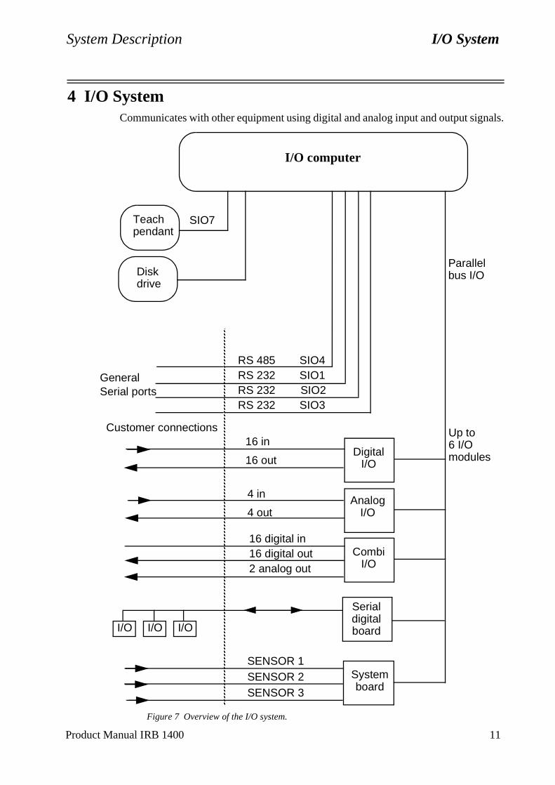
4 I/O SystemCommunicates with other equipment using digital and analog input and output signals.
Figure 7 Overview of the I/O system.
DigitalI/O
AnalogI/O
CombiI/O
Systemboard
Serial digital board
RS 485 SIO4RS 232 SIO1RS 232 SIO2RS 232 SIO3
AA
AAAAAAAAAAAAAAAAAAAAAAAAAAAAAAAAAAAAAAAAAAAAAAAAAAAAAAAAAAAAAAAAAAAAAAAAAAAAAAAAAAAAAAAAAAAAAAAAAAAAAAAAAAAAAAAAAAAAAAAAAAAAAAAAAAAAAAAAAAAAAAAAAAAAAAAAAAAAAAAAAAAAAAAAAAAAAAAAAAAAAAAAAAAAAAAAAAAAAAAAAAAAAAAAAAAAAAAAAAAAAAAAAAAAAAAAAAAAAAAAAAAAAAAAAAAAAAAAAAAAAAAAAAAAAAAAAAAAAAAAAAAAAAAAAAAAAAAAAAAAAAAAAAAAAAAAAAAAAAAAAAAAAAAAAAAAAAAAAAAAAAAAAAAAAAAAAAAAAAAAAAAAAAAAAAAAAAAAAAAAAAAAAAAAAAAAAAAAAAAAAAAAAAAAAAAAAAAAAAAAAAAAAA
GeneralSerial ports
I/O I/O I/O
Customer connections16 in
16 out
4 in
4 out
16 digital in16 digital out2 analog out
SENSOR 1SENSOR 2SENSOR 3
I/O computer
Teachpendant
Diskdrive
SIO7
Parallel bus I/O
Up to 6 I/O modules
Motion and I/O Principles Coordinate Systems
RAPID Reference Manual 6-3
1 Coordinate Systems
1.1 The robot’s tool centre point (TCP)
The position of the robot and its movements are always related to the tool centre point. This point is normally defined as being somewhere on the tool, e.g. in the muzzle of a glue gun, at the centre of a gripper or at the end of a grading tool.
Several TCPs (tools) may be defined, but only one may be active at any one time. When a position is recorded, it is the position of the TCP that is recorded. This is also the point that moves along a given path, at a given velocity.
If the robot is holding a work object and working on a stationary tool, a stationary TCP is used. If that tool is active, the programmed path and speed are related to the work object. See Stationary TCPs on page 10.
1.2 Coordinate systems used to determine the position of the TCP
The tool (TCP’s) position can be specified in different coordinate systems to facilitate programming and readjustment of programs.
The coordinate system defined depends on what the robot has to do. When no coordinate system is defined, the robot’s positions are defined in the base coordinate system.
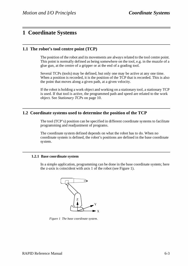
1.2.1 Base coordinate system
In a simple application, programming can be done in the base coordinate system; here the z-axis is coincident with axis 1 of the robot (see Figure 1).
Figure 1 The base coordinate system.
Z
X
Y
Coordinate Systems Motion and I/O Principles
6-4 RAPID Reference Manual
The base coordinate system is located on the base of the robot:
- The origin is situated at the intersection of axis 1 and the base mounting surface.
- The xy plane is the same as the base mounting surface.
- The x-axis points forwards.
- The y-axis points to the left (from the perspective of the robot).
- The z-axis points upwards.
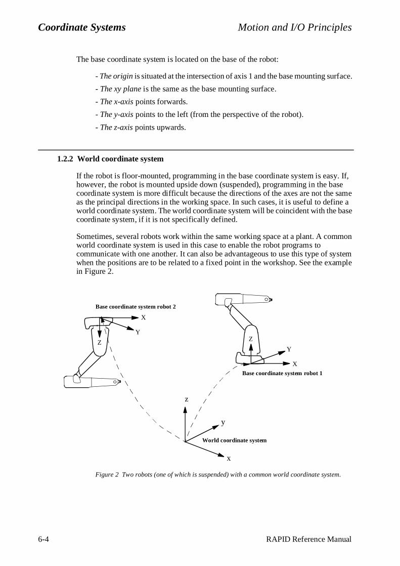
1.2.2 World coordinate system
If the robot is floor-mounted, programming in the base coordinate system is easy. If, however, the robot is mounted upside down (suspended), programming in the base coordinate system is more difficult because the directions of the axes are not the same as the principal directions in the working space. In such cases, it is useful to define a world coordinate system. The world coordinate system will be coincident with the base coordinate system, if it is not specifically defined.
Sometimes, several robots work within the same working space at a plant. A common world coordinate system is used in this case to enable the robot programs to communicate with one another. It can also be advantageous to use this type of system when the positions are to be related to a fixed point in the workshop. See the example in Figure 2.
Figure 2 Two robots (one of which is suspended) with a common world coordinate system.
Base coordinate system robot 2
x
y
z
World coordinate system
Base coordinate system robot 1
Z
X
YZ
X
Y
Motion and I/O Principles Coordinate Systems
RAPID Reference Manual 6-5
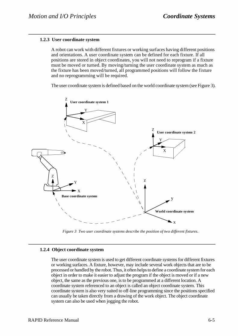
1.2.3 User coordinate system
A robot can work with different fixtures or working surfaces having different positions and orientations. A user coordinate system can be defined for each fixture. If all positions are stored in object coordinates, you will not need to reprogram if a fixture must be moved or turned. By moving/turning the user coordinate system as much as the fixture has been moved/turned, all programmed positions will follow the fixture and no reprogramming will be required.
The user coordinate system is defined based on the world coordinate system (see Figure 3).
Figure 3 Two user coordinate systems describe the position of two different fixtures.
1.2.4 Object coordinate system
The user coordinate system is used to get different coordinate systems for different fixtures or working surfaces. A fixture, however, may include several work objects that are to be processed or handled by the robot. Thus, it often helps to define a coordinate system for each object in order to make it easier to adjust the program if the object is moved or if a new object, the same as the previous one, is to be programmed at a different location. A coordinate system referenced to an object is called an object coordinate system. This coordinate system is also very suited to off-line programming since the positions specified can usually be taken directly from a drawing of the work object. The object coordinate system can also be used when jogging the robot.
Base coordinate system
x
y
z
World coordinate system
User coordinate system 1
Z
X
Y
Y
Z
X
User coordinate system 2
Y
Z
X
Coordinate Systems Motion and I/O Principles
6-6 RAPID Reference Manual
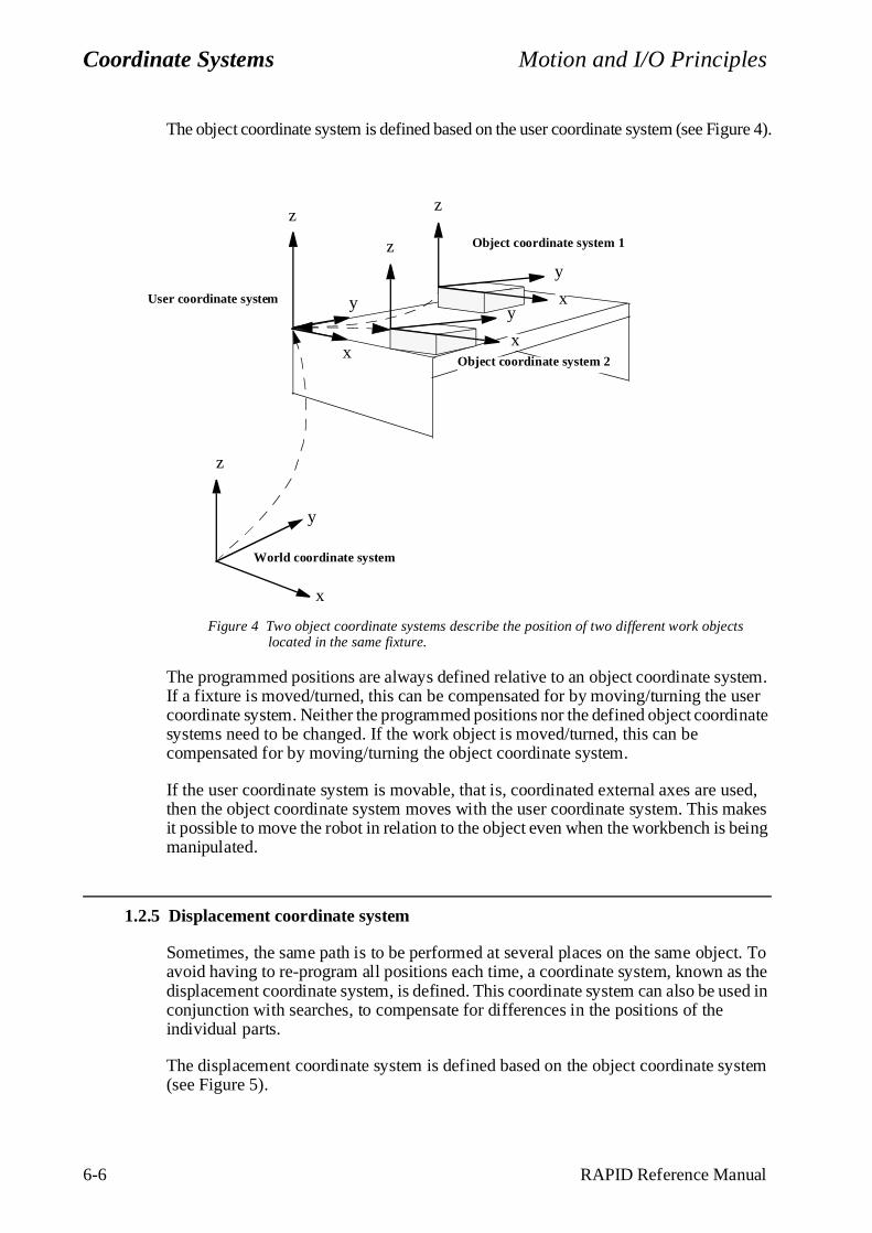
The object coordinate system is defined based on the user coordinate system (see Figure 4).
Figure 4 Two object coordinate systems describe the position of two different work objects located in the same fixture.
The programmed positions are always defined relative to an object coordinate system. If a fixture is moved/turned, this can be compensated for by moving/turning the user coordinate system. Neither the programmed positions nor the defined object coordinate systems need to be changed. If the work object is moved/turned, this can be compensated for by moving/turning the object coordinate system.
If the user coordinate system is movable, that is, coordinated external axes are used, then the object coordinate system moves with the user coordinate system. This makes it possible to move the robot in relation to the object even when the workbench is being manipulated.
1.2.5 Displacement coordinate system
Sometimes, the same path is to be performed at several places on the same object. To avoid having to re-program all positions each time, a coordinate system, known as the displacement coordinate system, is defined. This coordinate system can also be used in conjunction with searches, to compensate for differences in the positions of the individual parts.
The displacement coordinate system is defined based on the object coordinate system (see Figure 5).
User coordinate system
x
y
z
World coordinate system
Object coordinate system 2
yy
z
z
xx
y
z
x
Object coordinate system 1
Motion and I/O Principles Coordinate Systems
RAPID Reference Manual 6-7
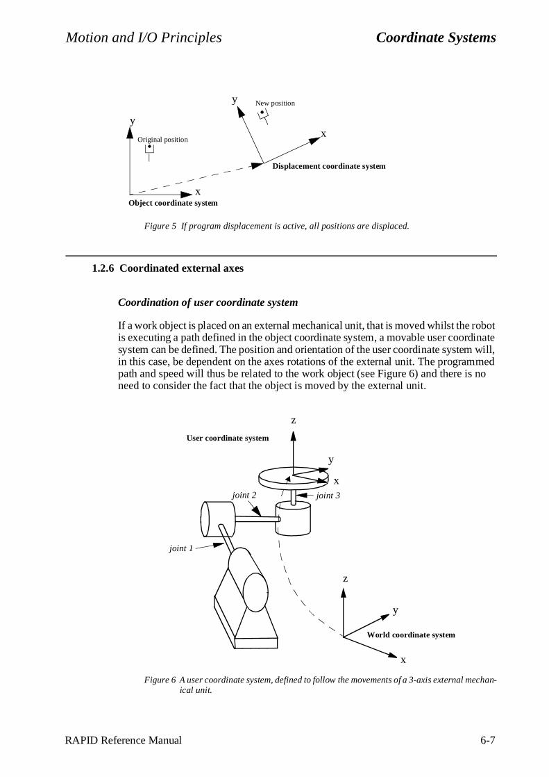
Figure 5 If program displacement is active, all positions are displaced.
1.2.6 Coordinated external axes
Coordination of user coordinate system
If a work object is placed on an external mechanical unit, that is moved whilst the robot is executing a path defined in the object coordinate system, a movable user coordinate system can be defined. The position and orientation of the user coordinate system will, in this case, be dependent on the axes rotations of the external unit. The programmed path and speed will thus be related to the work object (see Figure 6) and there is no need to consider the fact that the object is moved by the external unit.
Figure 6 A user coordinate system, defined to follow the movements of a 3-axis external mechan-ical unit.
Original position
New position
x
yx
y
Object coordinate system
Displacement coordinate system
joint 1
joint 2 joint 3
x
y
z
World coordinate system
User coordinate system
y
z
x
Coordinate Systems Motion and I/O Principles
6-8 RAPID Reference Manual
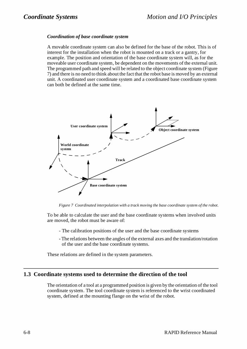
Coordination of base coordinate system
A movable coordinate system can also be defined for the base of the robot. This is of interest for the installation when the robot is mounted on a track or a gantry, for example. The position and orientation of the base coordinate system will, as for the moveable user coordinate system, be dependent on the movements of the external unit. The programmed path and speed will be related to the object coordinate system (Figure 7) and there is no need to think about the fact that the robot base is moved by an external unit. A coordinated user coordinate system and a coordinated base coordinate system can both be defined at the same time.
Figure 7 Coordinated interpolation with a track moving the base coordinate system of the robot.
To be able to calculate the user and the base coordinate systems when involved units are moved, the robot must be aware of:
- The calibration positions of the user and the base coordinate systems
- The relations between the angles of the external axes and the translation/rotation of the user and the base coordinate systems.
These relations are defined in the system parameters.
1.3 Coordin ate systems used to determine the direction of the tool
The orientation of a tool at a programmed position is given by the orientation of the tool coordinate system. The tool coordinate system is referenced to the wrist coordinated system, defined at the mounting flange on the wrist of the robot.
Object coordinate system
Base coordinate system
World coordinate system
Track
User coordinate system
Motion and I/O Principles Coordinate Systems
RAPID Reference Manual 6-9
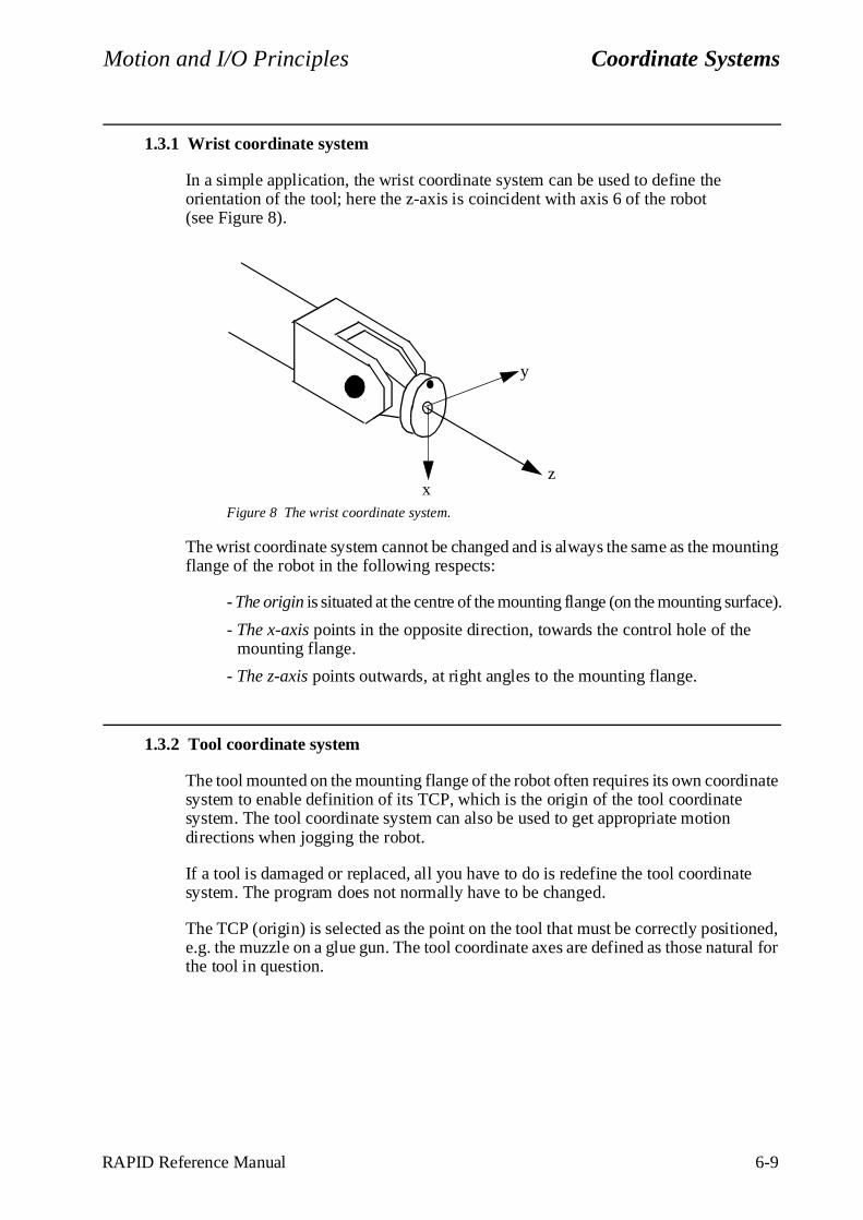
1.3.1 Wrist coordinate system
In a simple application, the wrist coordinate system can be used to define the orientation of the tool; here the z-axis is coincident with axis 6 of the robot (see Figure 8).
Figure 8 The wrist coordinate system.
The wrist coordinate system cannot be changed and is always the same as the mounting flange of the robot in the following respects:
- The origin is situated at the centre of the mounting flange (on the mounting surface).
- The x-axis points in the opposite direction, towards the control hole of the mounting flange.
- The z-axis points outwards, at right angles to the mounting flange.
1.3.2 Tool coordinate system
The tool mounted on the mounting flange of the robot often requires its own coordinate system to enable definition of its TCP, which is the origin of the tool coordinate system. The tool coordinate system can also be used to get appropriate motion directions when jogging the robot.
If a tool is damaged or replaced, all you have to do is redefine the tool coordinate system. The program does not normally have to be changed.
The TCP (origin) is selected as the point on the tool that must be correctly positioned, e.g. the muzzle on a glue gun. The tool coordinate axes are defined as those natural for the tool in question.
xz
y
Coordinate Systems Motion and I/O Principles
6-10 RAPID Reference Manual
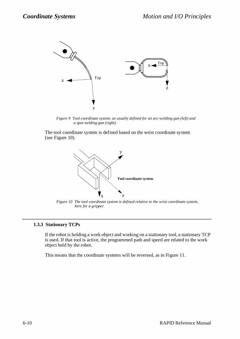
Figure 9 Tool coordinate system, as usually defined for an arc-welding gun (left) and a spot welding gun (right).
The tool coordinate system is defined based on the wrist coordinate system (see Figure 10).
Figure 10 The tool coordinate system is defined relative to the wrist coordinate system, here for a gripper.
1.3.3 Stationary TCPs
If the robot is holding a work object and working on a stationary tool, a stationary TCP is used. If that tool is active, the programmed path and speed are related to the work object held by the robot.
This means that the coordinate systems will be reversed, as in Figure 11.
Topx
z
x
z
Top
z
y
x
Tool coordinate system
Motion and I/O Principles Coordinate Systems
RAPID Reference Manual 6-11
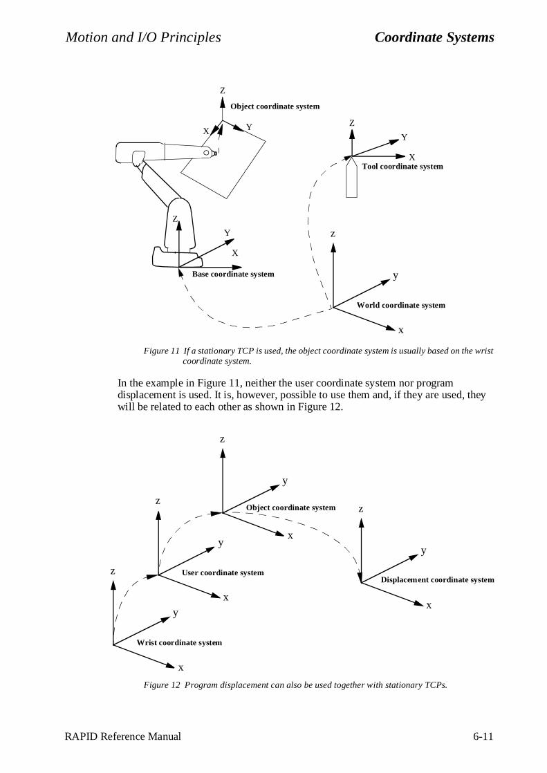
Figure 11 If a stationary TCP is used, the object coordinate system is usually based on the wrist coordinate system.
In the example in Figure 11, neither the user coordinate system nor program displacement is used. It is, however, possible to use them and, if they are used, they will be related to each other as shown in Figure 12.
Figure 12 Program displacement can also be used together with stationary TCPs.
Base coordinate system
x
y
z
World coordinate system
Z
X
Y
Tool coordinate system
Z
X
Y
Z
YX
Object coordinate system
x
y
z
Wrist coordinate system
x
y
z
Object coordinate system
x
y
z
User coordinate system
x
y
z
Displacement coordinate system
yp j
RAPID Reference Manual 7-wobjdata-1
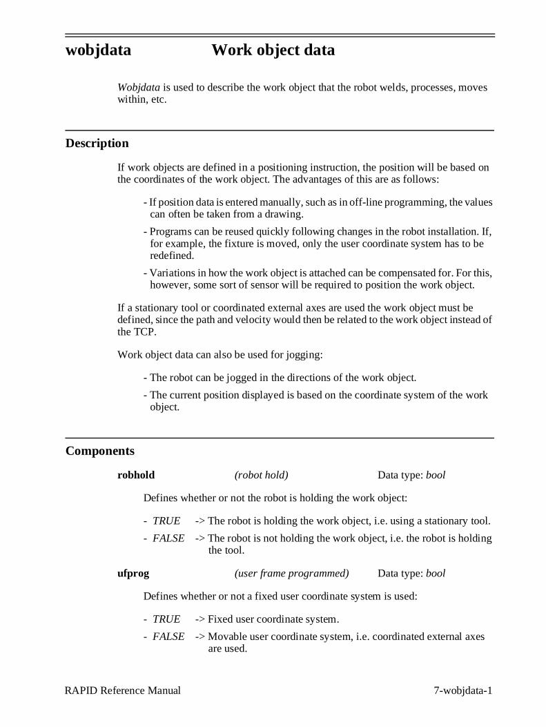
wobjdata Work object data
Wobjdata is used to describe the work object that the robot welds, processes, moves within, etc.
Description
If work objects are defined in a positioning instruction, the position will be based on the coordinates of the work object. The advantages of this are as follows:
- If position data is entered manually, such as in off-line programming, the values can often be taken from a drawing.
- Programs can be reused quickly following changes in the robot installation. If, for example, the fixture is moved, only the user coordinate system has to be redefined.
- Variations in how the work object is attached can be compensated for. For this, however, some sort of sensor will be required to position the work object.
If a stationary tool or coordinated external axes are used the work object must be defined, since the path and velocity would then be related to the work object instead of the TCP.
Work object data can also be used for jogging:
- The robot can be jogged in the directions of the work object.
- The current position displayed is based on the coordinate system of the work object.
Components
robhold (robot hold) Data type: bool
Defines whether or not the robot is holding the work object:
- TRUE -> The robot is holding the work object, i.e. using a stationary tool.
- FALSE -> The robot is not holding the work object, i.e. the robot is holding the tool.
ufprog (user frame programmed) Data type: bool
Defines whether or not a fixed user coordinate system is used:
- TRUE -> Fixed user coordinate system.
- FALSE -> Movable user coordinate system, i.e. coordinated external axes are used.
j yp
7-wobjdata-2 RAPID Reference Manual
ufmec (user frame mechanical unit) Data type: string
The mechanical unit with which the robot movements are coordinated. Only specified in the case of movable user coordinate systems (ufprog is FALSE).
Specified with the name that is defined in the system parameters, e.g. "orbit_a".
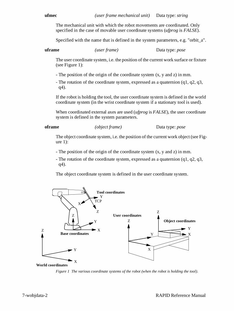
uframe (user frame) Data type: pose
The user coordinate system, i.e. the position of the current work surface or fixture (see Figure 1):
- The position of the origin of the coordinate system (x, y and z) in mm.
- The rotation of the coordinate system, expressed as a quaternion (q1, q2, q3, q4).
If the robot is holding the tool, the user coordinate system is defined in the world coordinate system (in the wrist coordinate system if a stationary tool is used).
When coordinated external axes are used (ufprog is FALSE), the user coordinate system is defined in the system parameters.
oframe (object frame) Data type: pose
The object coordinate system, i.e. the position of the current work object (see Fig-ure 1):
- The position of the origin of the coordinate system (x, y and z) in mm.
- The rotation of the coordinate system, expressed as a quaternion (q1, q2, q3, q4).
The object coordinate system is defined in the user coordinate system.
Figure 1 The various coordinate systems of the robot (when the robot is holding the tool).
AAAAAAAAAAAAAAAAAAAAAAAAAAAAAAAAAAAA
AAAAAAAAAAAAAAAAAA
Tool coordinates
Object coordinates
Base coordinatesZ
Y
XWorld coordinates
User coordinatesZ
Z
Y
Y
X
X
X
Y
ZZ
X
Y
TCP
yp j
RAPID Reference Manual 7-wobjdata-3
Example
PERS wobjdata wobj2 :=[ FALSE, TRUE, "", [ [300, 600, 200], [1, 0, 0 ,0] ],[ [0, 200, 30], [1, 0, 0 ,0] ] ];
The work object in Figure 1 is described using the following values:
- The robot is not holding the work object.
- The fixed user coordinate system is used.
- The user coordinate system is not rotated and the coordinates of its origin are x= 300, y = 600 and z = 200 mm in the world coordinate system.
- The object coordinate system is not rotated and the coordinates of its origin are x= 0, y= 200 and z= 30 mm in the user coordinate system.
wobj2.oframe.trans.z := 38.3;
- The position of the work object wobj2 is adjusted to 38.3 mm in the z-direction.
Limitations
The work object data should be defined as a persistent variable (PERS) and should not be defined within a routine. The current values are then saved when the program is stored on diskette and are retrieved on loading.
Arguments of the type work object data in any motion instruction should only be an entire persistent (not array element or record component).
Predefined data
The work object data wobj0 is defined in such a way that the object coordinate system coincides with the world coordinate system. The robot does not hold the work object.
Wobj0 can always be accessed from the program, but can never be changed (it is stored in system module BASE).
PERS wobjdata wobj0 := [ FALSE, TRUE, "", [ [0, 0, 0], [1, 0, 0 ,0] ], [ [0, 0, 0], [1, 0, 0 ,0] ] ];
j yp
7-wobjdata-4 RAPID Reference Manual
Structure
< dataobject of wobjdata >< robhold of bool >< ufprog of bool>< ufmec of string >< uframe of pose >
< trans of pos >< x of num >< y of num >< z of num >
< rot of orient >< q1 of num >< q2 of num >< q3 of num >< q4 of num >
< oframe of pose >< trans of pos >
< x of num >< y of num >< z of num >
< rot of orient >< q1 of num >< q2 of num >< q3 of num >< q4 of num >
Related information
Described in:
Positioning instructions RAPID Summary - Motion
Coordinate systems Motion and I/O Principles - Coordi-nate Systems
Coordinated external axes Motion and I/O Principles - Coordi-nate Systems
Calibration of coordinated external axes User’s Guide - System Parameters
Calibration
10-28 User’s Guide
7 Defining Tools
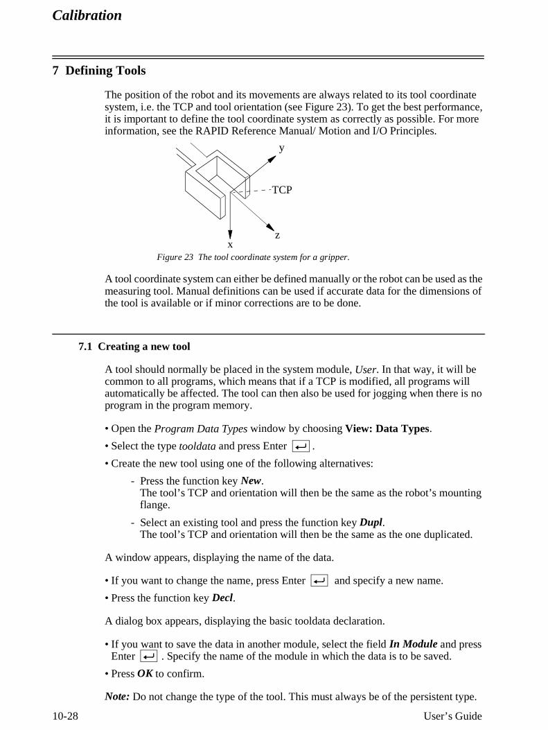
The position of the robot and its movements are always related to its tool coordinate system, i.e. the TCP and tool orientation (see Figure 23). To get the best performance, it is important to define the tool coordinate system as correctly as possible. For more information, see the RAPID Reference Manual/ Motion and I/O Principles.
Figure 23 The tool coordinate system for a gripper.
A tool coordinate system can either be defined manually or the robot can be used as the measuring tool. Manual definitions can be used if accurate data for the dimensions of the tool is available or if minor corrections are to be done.
7.1 Creating a new tool
A tool should normally be placed in the system module, User. In that way, it will be common to all programs, which means that if a TCP is modified, all programs will automatically be affected. The tool can then also be used for jogging when there is no program in the program memory.
• Open the Program Data Types window by choosing View: Data Types.
• Select the type tooldata and press Enter .
• Create the new tool using one of the following alternatives:
- Press the function key New. The tool’s TCP and orientation will then be the same as the robot’s mounting flange.
- Select an existing tool and press the function key Dupl. The tool’s TCP and orientation will then be the same as the one duplicated.
A window appears, displaying the name of the data.
• If you want to change the name, press Enter and specify a new name.
• Press the function key Decl.
A dialog box appears, displaying the basic tooldata declaration.
• If you want to save the data in another module, select the field In Module and press Enter . Specify the name of the module in which the data is to be saved.
• Press OK to confirm.
Note: Do not change the type of the tool. This must always be of the persistent type.
z
y
x
TCP
Calibration
User’s Guide 10-29
7.2 Manually updating the TCP and weight of a tool
• Open the Program Data Types window by choosing View: Data Types.
• Select the type tooldata and press Enter .
• Select the tool to be changed and press Enter .
• Select the TCP component (x, y, z) that you wish to change.
• Change the value using the numeric keyboard. To enter a decimal point ( . ) or minus sign ( - ), use the function keys.
• Select the mass component.
• Change the weight using the numeric keyboard.
• If the tool is stationary, i.e. not mounted on the robot, change the component robhold to FALSE. For more information about stationary tools see Stationary tool on page 33.
• Choose OK to confirm the change.
Note: Only the mass of the tool should be specified. A payload handled by a gripper is specified by the instruction GripLoad.
7.3 Methods of defining the tool coordinate system
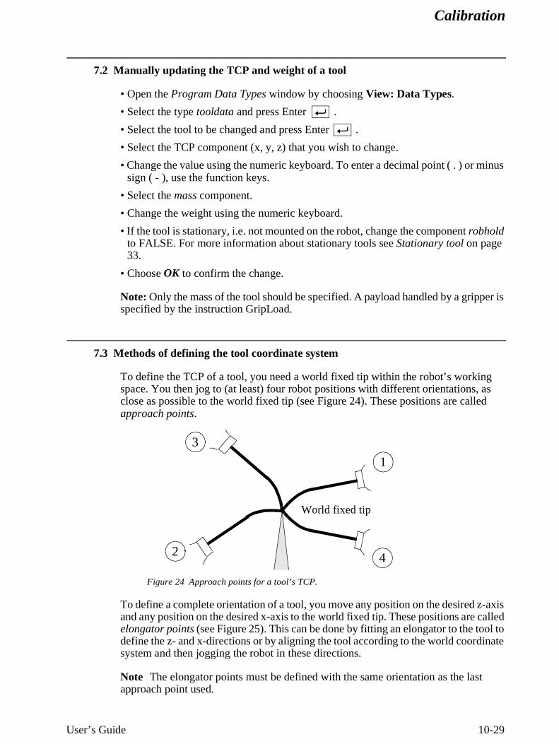
To define the TCP of a tool, you need a world fixed tip within the robot’s working space. You then jog to (at least) four robot positions with different orientations, as close as possible to the world fixed tip (see Figure 24). These positions are called approach points.
Figure 24 Approach points for a tool’s TCP.
To define a complete orientation of a tool, you move any position on the desired z-axis and any position on the desired x-axis to the world fixed tip. These positions are called elongator points (see Figure 25). This can be done by fitting an elongator to the tool to define the z- and x-directions or by aligning the tool according to the world coordinate system and then jogging the robot in these directions.
Note The elongator points must be defined with the same orientation as the last approach point used.
World fixed tip
1
2
3
4
Calibration
10-30 User’s Guide
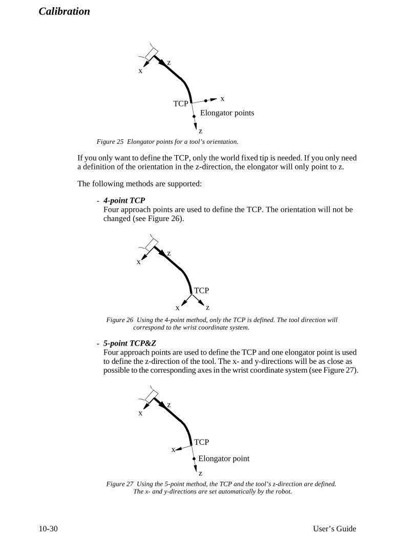
Figure 25 Elongator points for a tool’s orientation.
If you only want to define the TCP, only the world fixed tip is needed. If you only need a definition of the orientation in the z-direction, the elongator will only point to z.
The following methods are supported:
- 4-point TCPFour approach points are used to define the TCP. The orientation will not be changed (see Figure 26).
Figure 26 Using the 4-point method, only the TCP is defined. The tool direction will correspond to the wrist coordinate system.
- 5-point TCP&ZFour approach points are used to define the TCP and one elongator point is used to define the z-direction of the tool. The x- and y-directions will be as close as possible to the corresponding axes in the wrist coordinate system (see Figure 27).
Figure 27 Using the 5-point method, the TCP and the tool’s z-direction are defined. The x- and y-directions are set automatically by the robot.
xz
z
xTCP
Elongator points
xz
zx
TCP
xz
z
xTCP
Elongator point
Calibration
User’s Guide 10-31
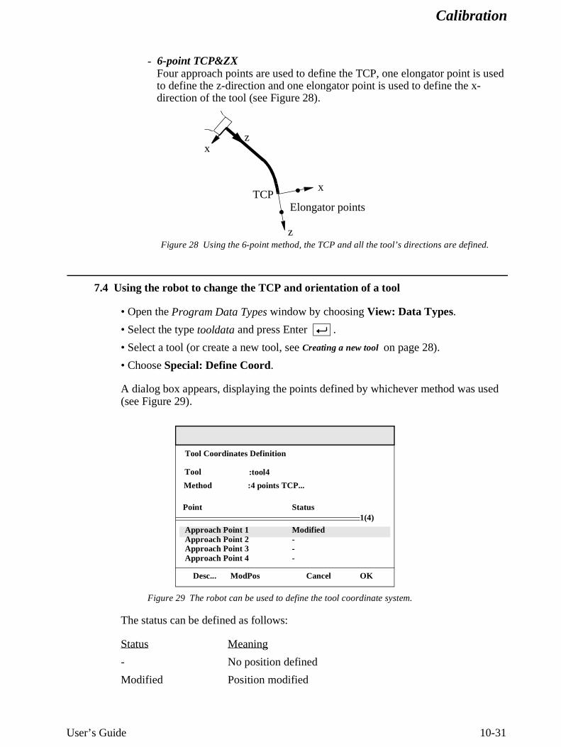
- 6-point TCP&ZXFour approach points are used to define the TCP, one elongator point is used to define the z-direction and one elongator point is used to define the x-direction of the tool (see Figure 28).
Figure 28 Using the 6-point method, the TCP and all the tool’s directions are defined.
7.4 Using the robot to change the TCP and orientation of a tool
• Open the Program Data Types window by choosing View: Data Types.
• Select the type tooldata and press Enter .
• Select a tool (or create a new tool, see Creating a new tool on page 28).
• Choose Special: Define Coord.
A dialog box appears, displaying the points defined by whichever method was used(see Figure 29).
Figure 29 The robot can be used to define the tool coordinate system.
The status can be defined as follows:
Status Meaning
- No position defined
Modified Position modified
xz
z
xTCP
Elongator points
Approach Point 1Approach Point 2Approach Point 3Approach Point 4
Desc... ModPos Cancel OK
1(4)
Tool Coordinates Definition
:tool4
Status
Modified---
Point
Method :4 points TCP...
Tool
Calibration
10-32 User’s Guide
To choose a definition method
Before you start modifying any positions, make sure the desired method is displayed. See Methods of defining the tool coordinate system on page 29.
• Select the field Method and press Enter .
• Choose a method and press OK.
To record Approach Points
• Select the first point Approach Point 1.
• Jog the robot as close as possible to the world fixed tip.
• Modify the position by pressing the function key ModPos.
• Repeat the above for the points Approach Point 2-4.
To record Elongator Point Z (if the 4-point TCP method is not used)
• Select Elongator z Point.
• Jog - without changing the orientation from the last approach point - any point on the desired positive z-axis to the world fixed tip. An extension should be fitted to obtain better accuracy.
• Modify the position by pressing the function key ModPos.
To record Elongator Point X (only if the 6-Point TCP&XZ method is used)
• Select Elongator x Point.
• Jog - without changing the orientation from the last approach point - any point on the desired positive x-axis to the world fixed tip.
• Modify the position by pressing the function key ModPos.
To calculate the tool coordinate system
• Press OK to calculate the tool coordinate system.
When the calculation is finished, a dialog like the one in Figure 30 will appear.
Calibration
User’s Guide 10-33
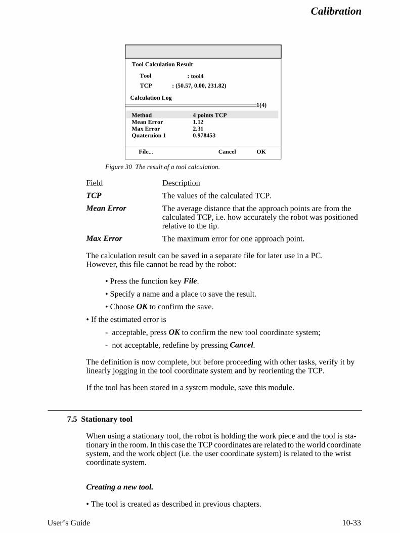
Figure 30 The result of a tool calculation.
Field Description
TCP The values of the calculated TCP.
Mean Error The average distance that the approach points are from the calculated TCP, i.e. how accurately the robot was positioned relative to the tip.
Max Error The maximum error for one approach point.
The calculation result can be saved in a separate file for later use in a PC.However, this file cannot be read by the robot:
• Press the function key File.
• Specify a name and a place to save the result.
• Choose OK to confirm the save.
• If the estimated error is
- acceptable, press OK to confirm the new tool coordinate system;
- not acceptable, redefine by pressing Cancel.
The definition is now complete, but before proceeding with other tasks, verify it by linearly jogging in the tool coordinate system and by reorienting the TCP.
If the tool has been stored in a system module, save this module.
7.5 Stationary tool
When using a stationary tool, the robot is holding the work piece and the tool is sta-tionary in the room. In this case the TCP coordinates are related to the world coordinate system, and the work object (i.e. the user coordinate system) is related to the wrist coordinate system.
Creating a new tool.
• The tool is created as described in previous chapters.
File... Cancel OK
Tool Calculation Result
Tool
MethodMean ErrorMax ErrorQuaternion 1
1(4)Calculation Log
TCP : (50.57, 0.00, 231.82)
: tool4
4 points TCP1.122.310.978453
Calibration
10-34 User’s Guide
• The component robhold is changed to FALSE.
Creating a corresponding work object
When using a stationary tool, it is also necessary to use a work object held by the robot.
• The work object is created as described in Creating a new work object on page 36.
• The component robhold is changed to TRUE.
Methods for defining the tool coordinate system
The methods are the same as for a TCP mounted on the robot. However in this case, the reference tip is mounted on the robot and the robot is moved, so as to bring the tip to the stationary tool TCP. The tip must be defined and activated as a tool before the def-inition of the stationary tool may be done.
• Define and activate the tool, which should be used as a pointing tip, and which is mounted on the robot.
• Now the same methods for defining the stationary tool may be used, as described in Manually updating the TCP and weight of a tool on page 29 and Using the robot to change the TCP and orientation of a tool on page 31. Use the robot mounted tip to point out the stationary TCP with four approach points, and if needed, the z- and x-directions of the axes.
The programming language RAPID
User’s Guide 9-3
The programming language RAPID
1 Programming a Position
1.1 Positioning instructions
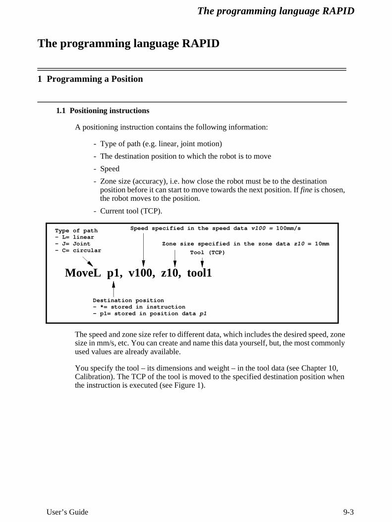
A positioning instruction contains the following information:
- Type of path (e.g. linear, joint motion)
- The destination position to which the robot is to move
- Speed
- Zone size (accuracy), i.e. how close the robot must be to the destination position before it can start to move towards the next position. If fine is chosen, the robot moves to the position.
- Current tool (TCP).
The speed and zone size refer to different data, which includes the desired speed, zone size in mm/s, etc. You can create and name this data yourself, but, the most commonly used values are already available.
You specify the tool – its dimensions and weight – in the tool data (see Chapter 10, Calibration). The TCP of the tool is moved to the specified destination position when the instruction is executed (see Figure 1).
MoveL p1, v100, z10, tool1
Type of path- L= linear- J= Joint- C= circular
Destination position- *= stored in instruction- p1= stored in position data p1
Speed specified in the speed data v100 = 100mm/s
Zone size specified in the zone data z10 = 10mm
Tool (TCP)
The programming language RAPID
9-4 User’s Guide
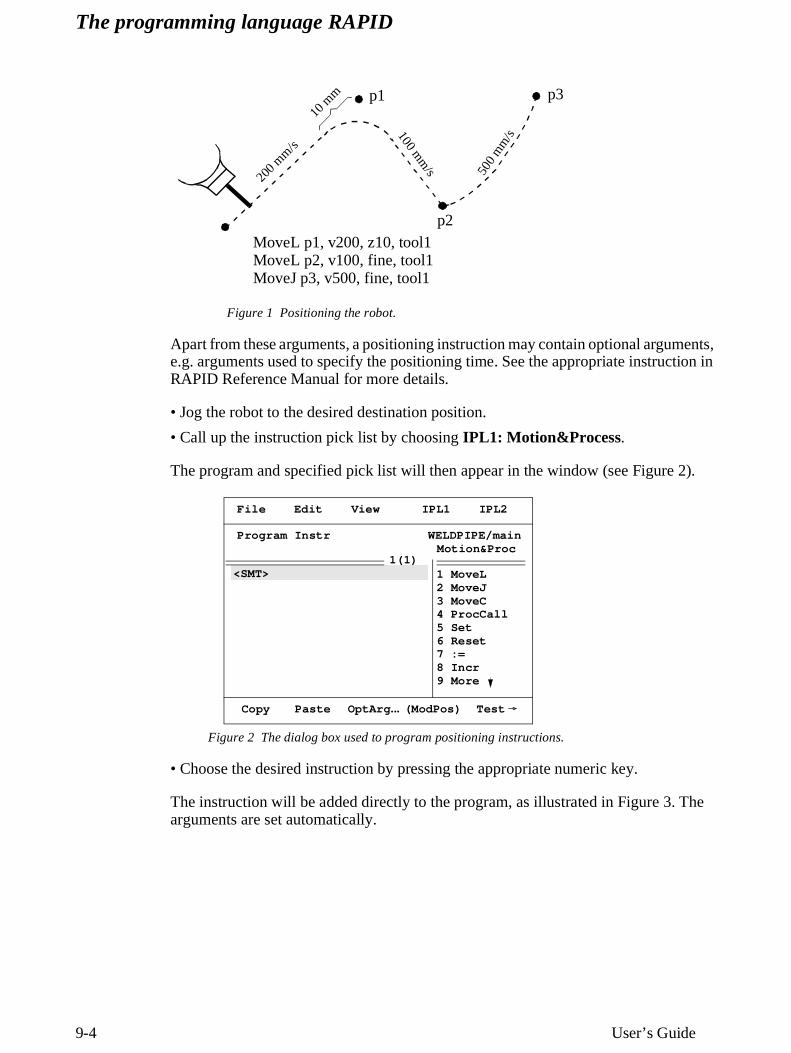
Figure 1 Positioning the robot.
Apart from these arguments, a positioning instruction may contain optional arguments, e.g. arguments used to specify the positioning time. See the appropriate instruction in RAPID Reference Manual for more details.
• Jog the robot to the desired destination position.
• Call up the instruction pick list by choosing IPL1: Motion&Process.
The program and specified pick list will then appear in the window (see Figure 2).
Figure 2 The dialog box used to program positioning instructions.
• Choose the desired instruction by pressing the appropriate numeric key.
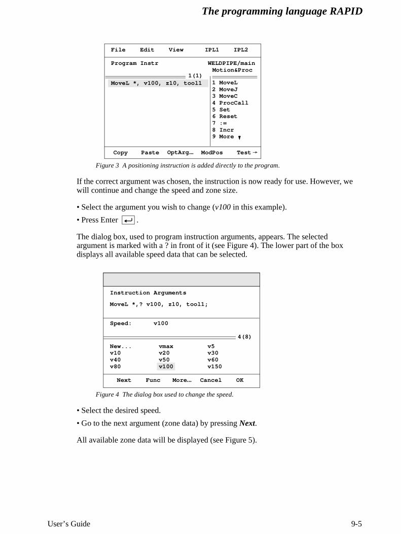
The instruction will be added directly to the program, as illustrated in Figure 3. The arguments are set automatically.
200 m
m/s
10 m
m
100 mm
/s
p1
p2
p3
500
mm
/s
MoveL p1, v200, z10, tool1MoveL p2, v100, fine, tool1MoveJ p3, v500, fine, tool1
<SMT> 1 MoveL2 MoveJ3 MoveC4 ProcCall5 Set6 Reset7 :=8 Incr9 More
Program Instr
File Edit View IPL1 IPL2
Copy Paste OptArg ... (ModPos) Test
WELDPIPE/mainMotion&Proc
1(1)
The programming language RAPID
User’s Guide 9-5
Figure 3 A positioning instruction is added directly to the program.
If the correct argument was chosen, the instruction is now ready for use. However, we will continue and change the speed and zone size.
• Select the argument you wish to change (v100 in this example).
• Press Enter .
The dialog box, used to program instruction arguments, appears. The selected argument is marked with a ? in front of it (see Figure 4). The lower part of the box displays all available speed data that can be selected.
Figure 4 The dialog box used to change the speed.
• Select the desired speed.
• Go to the next argument (zone data) by pressing Next.
All available zone data will be displayed (see Figure 5).
MoveL *, v100, z10, tool1
Program Instr
File Edit View IPL1 IPL2
WELDPIPE/mainMotion&Proc
1(1)
Copy Paste ModPos Test
1 MoveL2 MoveJ3 MoveC4 ProcCall5 Set6 Reset7 :=8 Incr9 More
OptArg ...
vmaxv20v50v100
v5v30v60v150
New...v10v40v80
4(8)
Speed: v100
Next Func More ... Cancel OK
Instruction Arguments
MoveL *,? v100, z10, tool1;
The programming language RAPID
9-6 User’s Guide
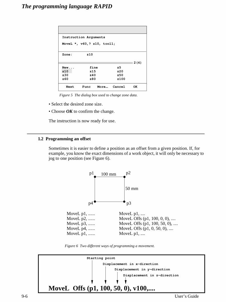
Figure 5 The dialog box used to change zone data.
• Select the desired zone size.
• Choose OK to confirm the change.
The instruction is now ready for use.
1.2 Programming an offset
Sometimes it is easier to define a position as an offset from a given position. If, for example, you know the exact dimensions of a work object, it will only be necessary to jog to one position (see Figure 6).
Figure 6 Two different ways of programming a movement.
finez15z40z80
z5z20z50z100
New...z10z30z60
Zone: z10
Next Func More ... Cancel OK
2(4)
Instruction Arguments
MoveL *, v60,? z10, tool1;
p1 p2
p3p4
100 mm
50 mm
MoveL p1, ......MoveL p2, ......MoveL p3, ......MoveL p4, ......MoveL p1, ......
MoveL p1, ....MoveL Offs (p1, 100, 0, 0), ....MoveL Offs (p1, 100, 50, 0), ....MoveL Offs (p1, 0, 50, 0), ....MoveL p1, ....
MoveL Offs (p1, 100, 50, 0), v100,....
Starting point
Displacement in x-direction
Displacement in y-direction
Displacement in z-direction
The programming language RAPID
User’s Guide 9-7
• Program a positioning instruction as described in Programming a Position on page 3.
• Select the position argument and press Enter .
• Press Func.
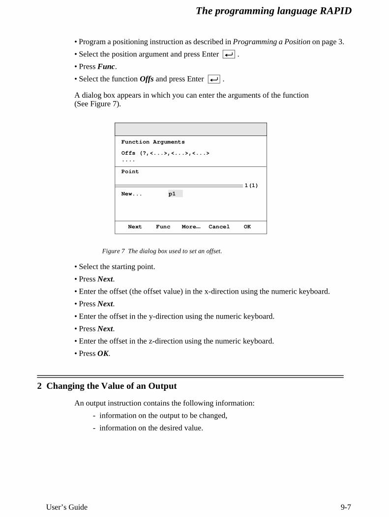
• Select the function Offs and press Enter .
A dialog box appears in which you can enter the arguments of the function(See Figure 7).
Figure 7 The dialog box used to set an offset.
• Select the starting point.
• Press Next.
• Enter the offset (the offset value) in the x-direction using the numeric keyboard.
• Press Next.
• Enter the offset in the y-direction using the numeric keyboard.
• Press Next.
• Enter the offset in the z-direction using the numeric keyboard.
• Press OK.
2 Changing the Value of an Output
An output instruction contains the following information:
- information on the output to be changed,
- information on the desired value.
Point
p1New...
Next Func More ... Cancel OK
1(1)
Function Arguments
Offs (?,<...>,<...>,<...>....
The programming language RAPID
9-8 User’s Guide
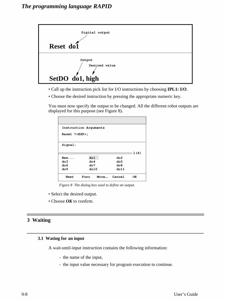
• Call up the instruction pick list for I/O instructions by choosing IPL1: I/O .
• Choose the desired instruction by pressing the appropriate numeric key.
You must now specify the output to be changed. All the different robot outputs are displayed for this purpose (see Figure 8).
Figure 8 The dialog box used to define an output.
• Select the desired output.
• Choose OK to confirm.
3 Waiting
3.1 Wating for an input
A wait-until-input instruction contains the following information:
- the name of the input,
- the input value necessary for program execution to continue.
Reset do1
Digital output
SetDO do1, high
Output
Desired value
do1do4do7do10
do2do5do8do11
New...do3do6do9
Signal:
Next Func More ... Cancel OK
1(4)
Instruction Arguments
Reset ?<EXP>;
The programming language RAPID
User’s Guide 9-9
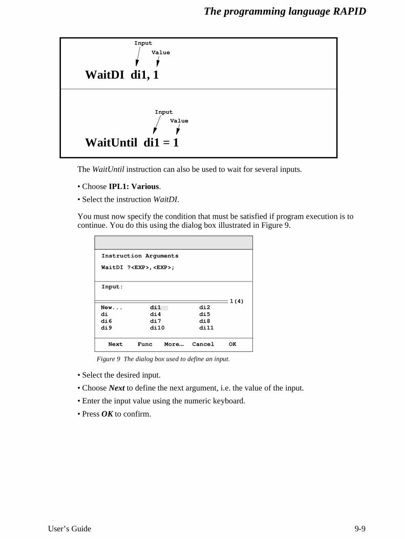
The WaitUntil instruction can also be used to wait for several inputs.
• Choose IPL1: Various .
• Select the instruction WaitDI.
You must now specify the condition that must be satisfied if program execution is to continue. You do this using the dialog box illustrated in Figure 9.
Figure 9 The dialog box used to define an input.
• Select the desired input.
• Choose Next to define the next argument, i.e. the value of the input.
• Enter the input value using the numeric keyboard.
• Press OK to confirm.
WaitDI di1, 1
Input
Value
WaitUntil di1 = 1
Input
Value
di1di4di7di10
di2di5di8di11
New...didi6di9
Input:
Next Func More ... Cancel OK
Instruction Arguments
WaitDI ?<EXP>,<EXP>;
1(4)
The programming language RAPID
9-10 User’s Guide
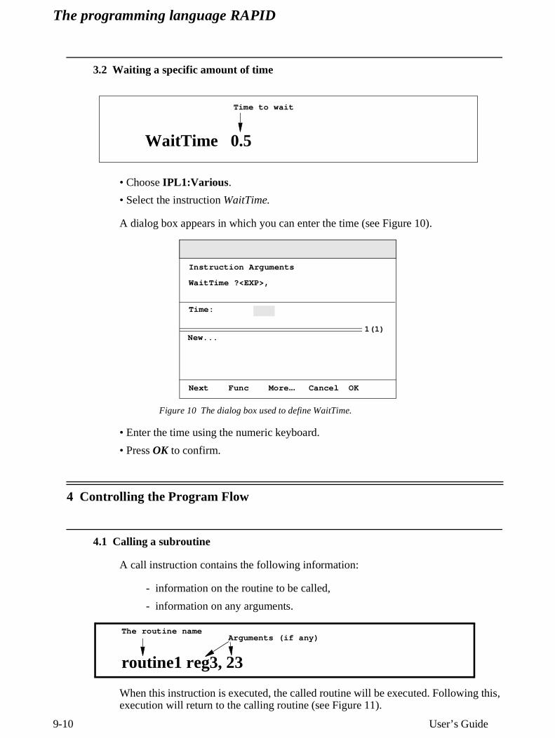
3.2 Waiting a specific amount of time
• Choose IPL1:Various .
• Select the instruction WaitTime.
A dialog box appears in which you can enter the time (see Figure 10).
Figure 10 The dialog box used to define WaitTime.
• Enter the time using the numeric keyboard.
• Press OK to confirm.
4 Controlling the Program Flow
4.1 Calling a subroutine
A call instruction contains the following information:
- information on the routine to be called,
- information on any arguments.
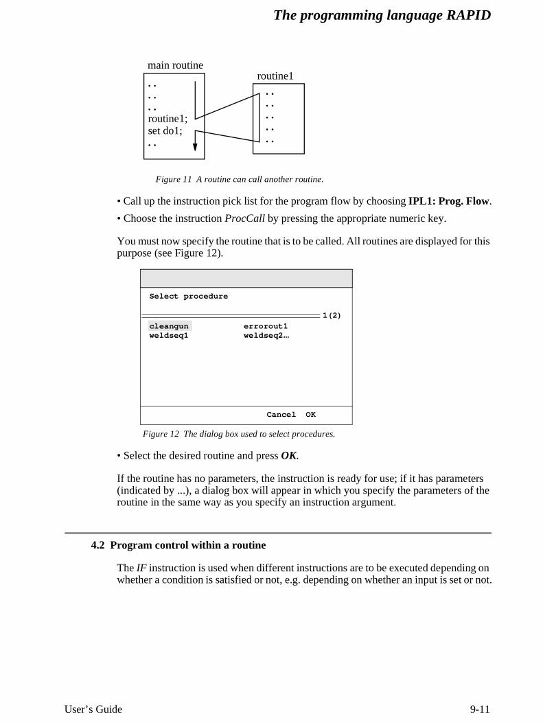
When this instruction is executed, the called routine will be executed. Following this, execution will return to the calling routine (see Figure 11).
WaitTime 0.5
Time to wait
Time:
New...
Next Func More ... Cancel OK
1(1)
Instruction Arguments
WaitTime ?<EXP>,
routine1 reg3, 23
The routine nameArguments (if any)
The programming language RAPID
User’s Guide 9-11
Figure 11 A routine can call another routine.
• Call up the instruction pick list for the program flow by choosing IPL1: Prog. Flow.
• Choose the instruction ProcCall by pressing the appropriate numeric key.
You must now specify the routine that is to be called. All routines are displayed for this purpose (see Figure 12).
Figure 12 The dialog box used to select procedures.
• Select the desired routine and press OK.
If the routine has no parameters, the instruction is ready for use; if it has parameters (indicated by ...), a dialog box will appear in which you specify the parameters of the routine in the same way as you specify an instruction argument.
4.2 Program control within a routine
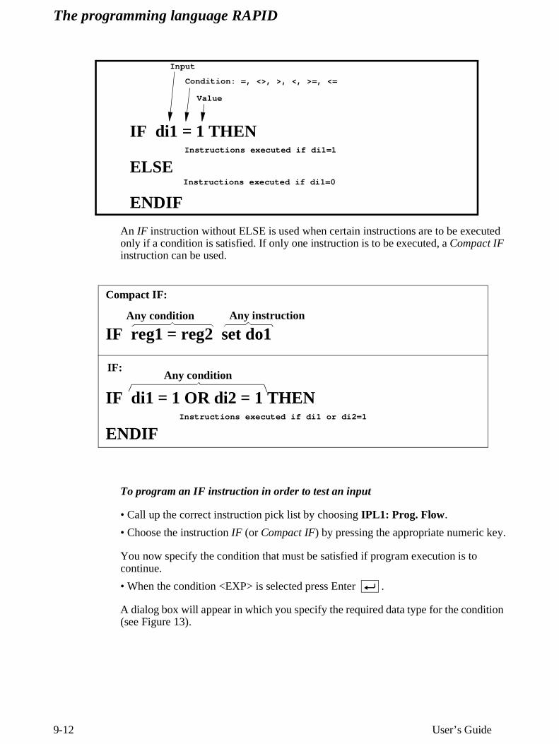
The IF instruction is used when different instructions are to be executed depending on whether a condition is satisfied or not, e.g. depending on whether an input is set or not.
. .
. .
. .routine1;set do1;. .
. .
. .
. .
. .
. .
main routineroutine1
cleangunweldseq1
Cancel OK
1(2)
Select procedure
errorout1weldseq2 ...
The programming language RAPID
9-12 User’s Guide
An IF instruction without ELSE is used when certain instructions are to be executed only if a condition is satisfied. If only one instruction is to be executed, a Compact IF instruction can be used.
To program an IF instruction in order to test an input
• Call up the correct instruction pick list by choosing IPL1: Prog. Flow.
• Choose the instruction IF (or Compact IF) by pressing the appropriate numeric key.
You now specify the condition that must be satisfied if program execution is to continue.
• When the condition <EXP> is selected press Enter .
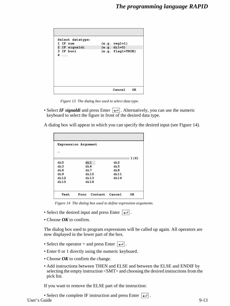
A dialog box will appear in which you specify the required data type for the condition (see Figure 13).
Condition: =, <>, >, <, >=, <=
IF di1 = 1 THEN
ELSE
ENDIF
Input
Value
Instructions executed if di1=1
Instructions executed if di1=0
IF di1 = 1 OR di2 = 1 THEN
ENDIFInstructions executed if di1 or di2=1
IF reg1 = reg2 set do1
Compact IF:
Any instructionAny condition
Any conditionIF:
The programming language RAPID
User’s Guide 9-13
Figure 13 The dialog box used to select data type.
• Select IF signaldi and press Enter . Alternatively, you can use the numeric keyboard to select the figure in front of the desired data type.
A dialog box will appear in which you can specify the desired input (see Figure 14).
Figure 14 The dialog box used to define expression arguments.
• Select the desired input and press Enter .
• Choose OK to confirm.
The dialog box used to program expressions will be called up again. All operators are now displayed in the lower part of the box.
• Select the operator = and press Enter .
• Enter 0 or 1 directly using the numeric keyboard.
• Choose OK to confirm the change.
• Add instructions between THEN and ELSE and between the ELSE and ENDIF by selecting the empty instruction <SMT> and choosing the desired instructions from the pick list.
If you want to remove the ELSE part of the instruction:
• Select the complete IF instruction and press Enter .
(e.g. reg1=1)(e.g. di1=0)(e.g. flag1=TRUE)
Cancel OK
Select datatype:1 IF num 2 IF signaldi3 IF bool4 ...
di1di4di7di10di13di16
di2di5di8di11di14
di0di3di6di9di12di15
Text Func Content Cancel OK
1(6)
Expression Argument
_
The programming language RAPID
9-14 User’s Guide
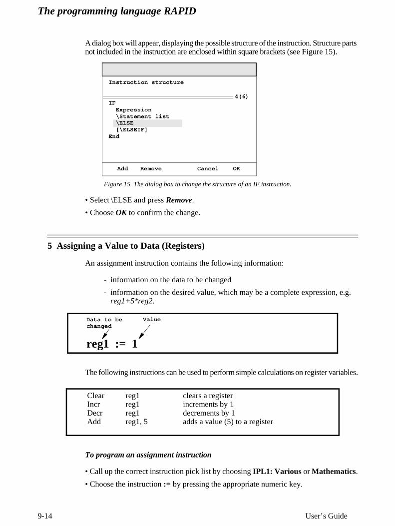
A dialog box will appear, displaying the possible structure of the instruction. Structure parts not included in the instruction are enclosed within square brackets (see Figure 15).
Figure 15 The dialog box to change the structure of an IF instruction.
• Select \ELSE and press Remove.
• Choose OK to confirm the change.
5 Assigning a Value to Data (Registers)
An assignment instruction contains the following information:
- information on the data to be changed
- information on the desired value, which may be a complete expression, e.g. reg1+5*reg2.
The following instructions can be used to perform simple calculations on register variables.
To program an assignment instruction
• Call up the correct instruction pick list by choosing IPL1: Various or Mathematics.
• Choose the instruction := by pressing the appropriate numeric key.
IFExpression
\Statement list\ELSE[\ELSEIF]
End
Add Remove Cancel OK
4(6)
Instruction structure
reg1 := 1
Data to bechanged
Value
ClearIncrDecrAdd
reg1reg1reg1reg1, 5
clears a registerincrements by 1decrements by 1adds a value (5) to a register
The programming language RAPID
User’s Guide 9-15
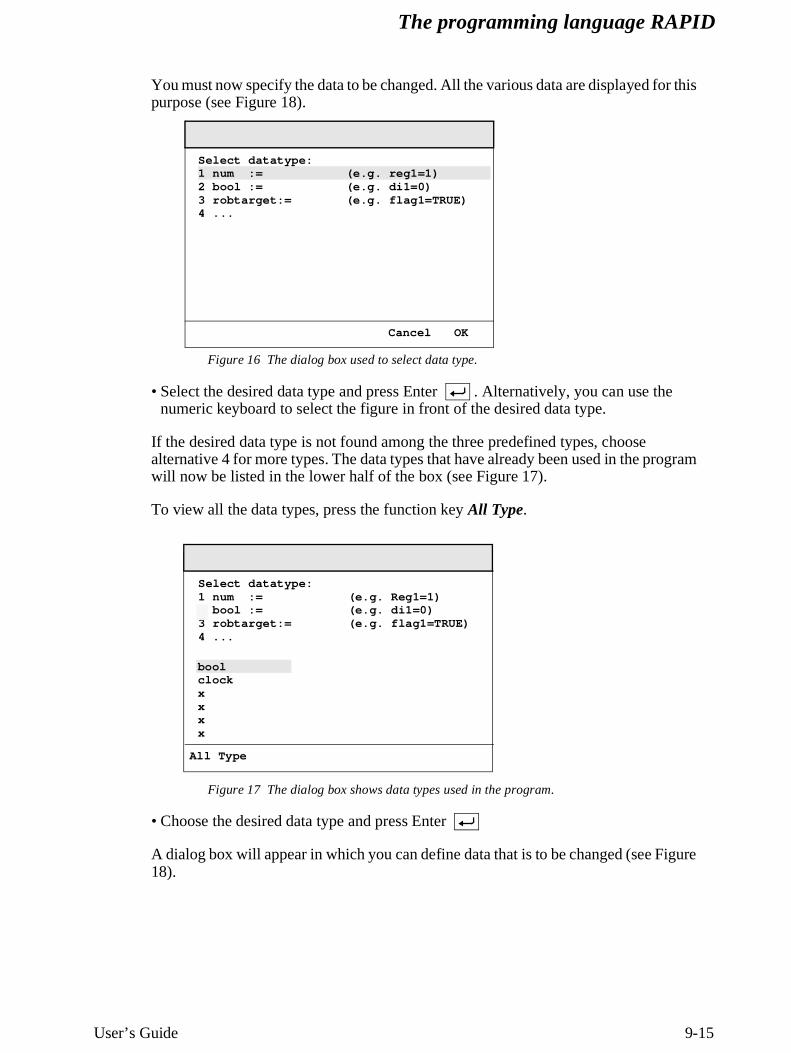
You must now specify the data to be changed. All the various data are displayed for this purpose (see Figure 18).
Figure 16 The dialog box used to select data type.
• Select the desired data type and press Enter . Alternatively, you can use the numeric keyboard to select the figure in front of the desired data type.
If the desired data type is not found among the three predefined types, choose alternative 4 for more types. The data types that have already been used in the program will now be listed in the lower half of the box (see Figure 17).
To view all the data types, press the function key All Type.
Figure 17 The dialog box shows data types used in the program.
• Choose the desired data type and press Enter
A dialog box will appear in which you can define data that is to be changed (see Figure 18).
Select datatype:1 num :=2 bool :=3 robtarget:=4 ...
Cancel OK
(e.g. reg1=1)(e.g. di1=0)(e.g. flag1=TRUE)
Select datatype:1 num :=2 bool :=3 robtarget:=4 ...
boolclockxxxx
All Type
(e.g. Reg1=1)(e.g. di1=0)(e.g. flag1=TRUE)
The programming language RAPID
9-16 User’s Guide
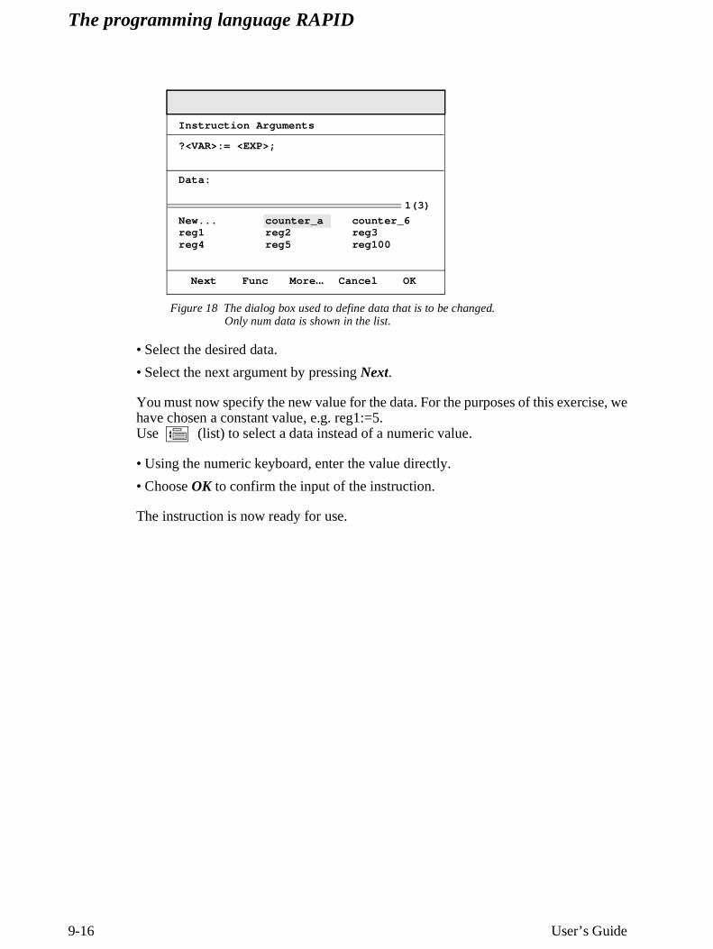
Figure 18 The dialog box used to define data that is to be changed. Only num data is shown in the list.
• Select the desired data.
• Select the next argument by pressing Next.
You must now specify the new value for the data. For the purposes of this exercise, we have chosen a constant value, e.g. reg1:=5. Use (list) to select a data instead of a numeric value.
• Using the numeric keyboard, enter the value directly.
• Choose OK to confirm the input of the instruction.
The instruction is now ready for use.
counter_areg2reg5
counter_6reg3reg100
New...reg1reg4
Data:
Next Func More ... Cancel OK
1(3)
Instruction Arguments
?<VAR>:= <EXP>;
RAPID Reference Manual 8-MoveC-1
MoveC Moves the robot circularly
MoveC is used to move the tool centre point (TCP) circularly to a given destination. Dur-ing the movement, the orientation normally remains unchanged relative to the circle.
Examples
MoveC p1, p2, v500, z30, tool2;
The TCP of the tool, tool2, is moved circularly to the position p2, with speed data v500 and zone data z30. The circle is defined from the start position, the circle point p1 and the destination point p2.
MoveC *, *, v500 \T:=5, fine, grip3;
The TCP of the tool, grip3, is moved circularly to a fine point stored in the instruction (marked by the second *). The circle point is also stored in the instruction (marked by the first *). The complete movement takes 5 seconds.
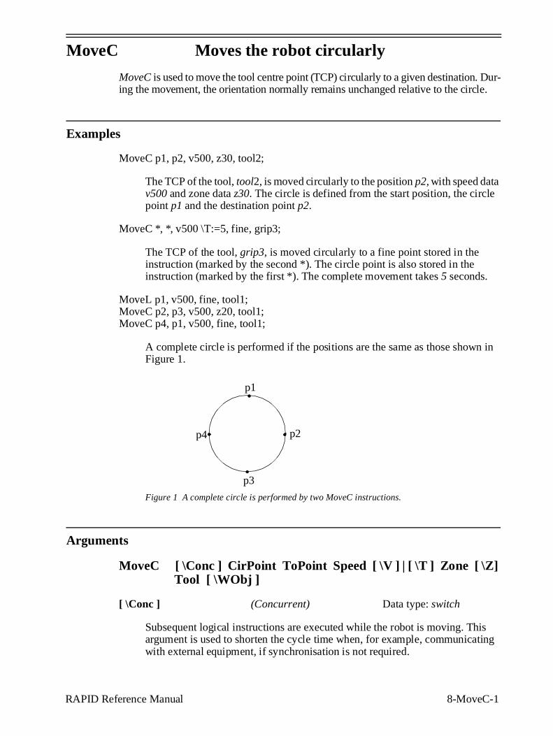
MoveL p1, v500, fine, tool1;MoveC p2, p3, v500, z20, tool1;MoveC p4, p1, v500, fine, tool1;
A complete circle is performed if the positions are the same as those shown in Figure 1.
Figure 1 A complete circle is performed by two MoveC instructions.
Arguments
MoveC [ \Conc ] CirPoint ToPoint Speed [ \V ] | [ \T ] Zone [ \Z] Tool [ \WObj ]
[ \Conc ] (Concurrent) Data type: switch
Subsequent logical instructions are executed while the robot is moving. This argument is used to shorten the cycle time when, for example, communicating with external equipment, if synchronisation is not required.
p1
p3
p2p4
8-MoveC-2 RAPID Reference Manual
Using the argument \Conc, the number of movement instructions in succession is limited to 5. In a program section that includes StorePath-RestoPath, movement instructions with the argument \Conc are not permitted.
If this argument is omitted, the subsequent instruction is only executed after the robot has reached the specified zone.
CirPoint Data type: robtarget
The circle point of the robot. The circle point is a position on the circle between the start point and the destination point. To obtain the best accuracy, it should be placed about halfway between the start and destination points. If it is placed too close to the start or destination point, the robot may give a warning. The circle point is defined as a named position or stored directly in the instruction (marked with an * in the instruction). The position of the external axes are not used.
ToPoint Data type: robtarget
The destination point of the robot and external axes. It is defined as a named posi-tion or stored directly in the instruction (marked with an * in the instruction).
Speed Data type: speeddata
The speed data that applies to movements. Speed data defines the velocity of the TCP, the tool reorientation and external axes.
[ \V ] (Velocity) Data type: num
This argument is used to specify the velocity of the TCP in mm/s directly in the instruction. It is then substituted for the corresponding velocity specified in the speed data.
[ \T ] (Time) Data type: num
This argument is used to specify the total time in seconds during which the robot and external axes move. It is then substituted for the corresponding speed data.
Zone Data type: zonedata
Zone data for the movement. Zone data describes the size of the generated corner path.
[ \Z ] (Zone) Data type: num
This argument is used to specify the position accuracy of the robot TCP directly in the instruction. The length of the corner path is given in mm, which is substi-tuted for the corresponding zone specified in the zone data.
Tool Data type: tooldata
The tool in use when the robot moves. The tool centre point is the point that is moved to the specified destination point.
RAPID Reference Manual 8-MoveC-3
[ \WObj] (Work Object) Data type: wobjdata
The work object (object coordinate system) to which the robot position in the instruction is related.
This argument can be omitted, and if it is, the position is related to the world coordinate system. If, on the other hand, a stationary TCP or coordinated exter-nal axes are used, this argument must be specified in order for a circle relative to the work object to be executed.
Program execution
The robot and external units are moved to the destination point as follows:
- The TCP of the tool is moved circularly at constant programmed velocity.
- The tool is reoriented at a constant velocity from the orientation at the start posi-tion to the orientation at the destination point.
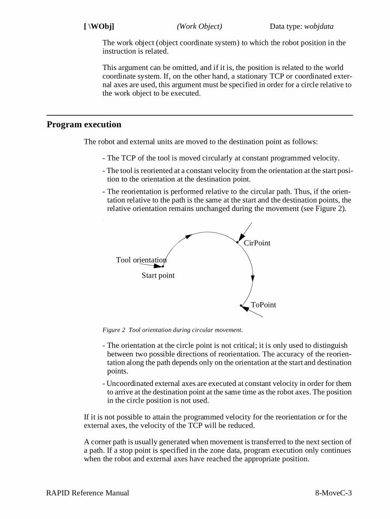
- The reorientation is performed relative to the circular path. Thus, if the orien-tation relative to the path is the same at the start and the destination points, the relative orientation remains unchanged during the movement (see Figure 2).
.
Figure 2 Tool orientation during circular movement.
- The orientation at the circle point is not critical; it is only used to distinguish between two possible directions of reorientation. The accuracy of the reorien-tation along the path depends only on the orientation at the start and destination points.
- Uncoordinated external axes are executed at constant velocity in order for them to arrive at the destination point at the same time as the robot axes. The position in the circle position is not used.
If it is not possible to attain the programmed velocity for the reorientation or for the external axes, the velocity of the TCP will be reduced.
A corner path is usually generated when movement is transferred to the next section of a path. If a stop point is specified in the zone data, program execution only continues when the robot and external axes have reached the appropriate position.
Start point
CirPoint
Tool orientation
ToPoint
8-MoveC-4 RAPID Reference Manual
Examples
MoveC *, *, v500 \V:=550, z40 \Z:=45, grip3;
The TCP of the tool, grip3, is moved circularly to a position stored in the instruc-tion. The movement is carried out with data set to v500 and z40; the velocity and zone size of the TCP are 550 mm/s and 45 mm respectively.
MoveC \Conc, *, *, v500, z40, grip3;
The TCP of the tool, grip3, is moved circularly to a position stored in the instruc-tion. The circle point is also stored in the instruction. Subsequent logical instruc-tions are executed while the robot moves.
MoveC cir1, p15, v500, z40, grip3 \WObj:=fixture;
The TCP of the tool, grip3, is moved circularly to a position, p15, via the circle point cir1. These positions are specified in the object coordinate system for fix-ture.
Limitations
A change of execution mode from forward to backward or vice versa, while the robot is stopped on a circular path, is not permitted and will result in an error message.
The instruction MoveC (or any other instruction including circular movement) should never be started from the beginning, with TCP between the circle point and the end point. Otherwise the robot will not take the programmed path (positioning around the circular path in another direction compared with that programmed).
Make sure that the robot can reach the circle point during program execution and divide the circle segment if necessary.
Syntax
MoveC [ ’\’ Conc ’,’ ][ CirPoint ’:=’ ] < expression (IN ) of robtarget > ’,’[ ToPoint ’:=’ ] < expression (IN ) of robtarget > ’,’[ Speed ’:=’ ] < expression (IN ) of speeddata >
[ ’\’ V ’:=’ < expression (IN ) of num > ] | [ ’\’ T ’:=’ < expression (IN ) of num > ] ’,’
[Zone ’:=’ ] < expression (IN ) of zonedata >[ ’\’ Z ’:=’ < expression (IN ) of num > ] ’,’
[ Tool ’:=’ ] < persistent (PERS) of tooldata > [ ’\’ WObj ’:=’ < persistent (PERS) of wobjdata > ] ’;’
RAPID Reference Manual 8-MoveC-5
Related information
Described in:
Other positioning instructions RAPID Summary - Motion
Definition of velocity Data Types - speeddata
Definition of zone data Data Types - zonedata
Definition of tools Data Types - tooldata
Definition of work objects Data Types - wobjdata
Motion in general Motion and I/O Principles
Coordinate systems Motion and I/O Principles - Coordinate Systems
Concurrent program execution Motion and I/O Principles - Synchronisation Using Logical Instructions
RAPID Reference Manual 8-MoveJ-1
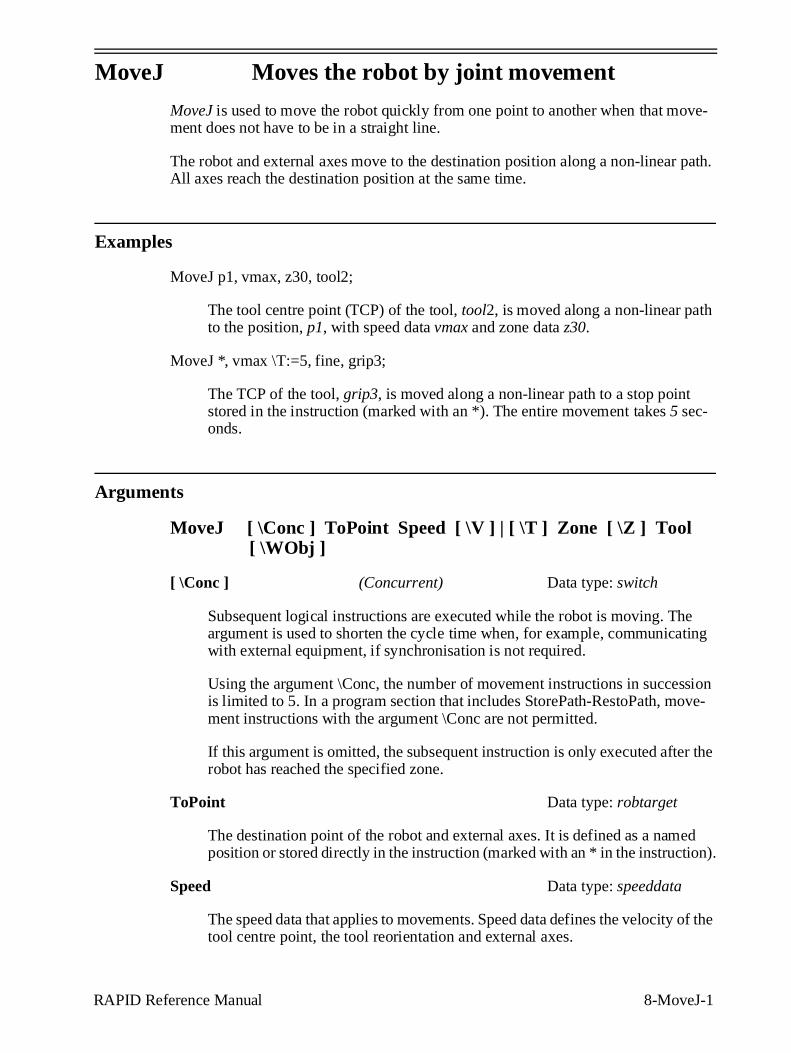
MoveJ Moves the robot by joint movement
MoveJ is used to move the robot quickly from one point to another when that move-ment does not have to be in a straight line.
The robot and external axes move to the destination position along a non-linear path. All axes reach the destination position at the same time.
Examples
MoveJ p1, vmax, z30, tool2;
The tool centre point (TCP) of the tool, tool2, is moved along a non-linear path to the position, p1, with speed data vmax and zone data z30.
MoveJ *, vmax \T:=5, fine, grip3;
The TCP of the tool, grip3, is moved along a non-linear path to a stop point stored in the instruction (marked with an *). The entire movement takes 5 sec-onds.
Arguments
MoveJ [ \Conc ] ToPoint Speed [ \V ] | [ \T ] Zone [ \Z ] Tool [ \WObj ]
[ \Conc ] (Concurrent) Data type: switch
Subsequent logical instructions are executed while the robot is moving. The argument is used to shorten the cycle time when, for example, communicating with external equipment, if synchronisation is not required.
Using the argument \Conc, the number of movement instructions in succession is limited to 5. In a program section that includes StorePath-RestoPath, move-ment instructions with the argument \Conc are not permitted.
If this argument is omitted, the subsequent instruction is only executed after the robot has reached the specified zone.
ToPoint Data type: robtarget
The destination point of the robot and external axes. It is defined as a named position or stored directly in the instruction (marked with an * in the instruction).
Speed Data type: speeddata
The speed data that applies to movements. Speed data defines the velocity of the tool centre point, the tool reorientation and external axes.
8-MoveJ-2 RAPID Reference Manual
[ \V ] (Velocity) Data type: num
This argument is used to specify the velocity of the TCP in mm/s directly in the instruction. It is then substituted for the corresponding velocity specified in the speed data.
[ \T ] (Time) Data type: num
This argument is used to specify the total time in seconds during which the robot moves. It is then substituted for the corresponding speed data.
Zone Data type: zonedata
Zone data for the movement. Zone data describes the size of the generated corner path.
[ \Z ] (Zone) Data type: num
This argument is used to specify the position accuracy of the robot TCP directly in the instruction. The length of the corner path is given in mm, which is substi-tuted for the corresponding zone specified in the zone data.
Tool Data type: tooldata
The tool in use when the robot moves. The tool centre point is the point moved to the specified destination point.
[ \WObj] (Work Object) Data type: wobjdata
The work object (coordinate system) to which the robot position in the instruction is related.
This argument can be omitted, and if it is, the position is related to the world coor-dinate system. If, on the other hand, a stationary TCP or coordinated external axes are used, this argument must be specified.
Program execution
The tool centre point is moved to the destination point with interpolation of the axis angles. This means that each axis is moved with constant axis velocity and that all axes reach the destination point at the same time, which results in a non-linear path.
Generally speaking, the TCP is moved at the approximate programmed velocity (regardless of whether or not the external axes are coordinated). The tool is reoriented and the external axes are moved at the same time as the TCP moves. If the programmed velocity for reorientation, or for the external axes, cannot be attained, the velocity of the TCP will be reduced.
A corner path is usually generated when movement is transferred to the next section of the path. If a stop point is specified in the zone data, program execution only continues when the robot and external axes have reached the appropriate position.
RAPID Reference Manual 8-MoveJ-3
Examples
MoveJ *, v2000\V:=2200, z40 \Z:=45, grip3;
The TCP of the tool, grip3, is moved along a non-linear path to a position stored in the instruction. The movement is carried out with data set to v2000 and z40; the velocity and zone size of the TCP are 2200 mm/s and 45 mm respectively.
MoveJ \Conc, *, v2000, z40, grip3;
The TCP of the tool, grip3, is moved along a non-linear path to a position stored in the instruction. Subsequent logical instructions are executed while the robot moves.
MoveJ start, v2000, z40, grip3 \WObj:=fixture;
The TCP of the tool, grip3, is moved along a non-linear path to a position, start. This position is specified in the object coordinate system for fixture.
Syntax
MoveJ [ ’\’ Conc ’,’ ][ ToPoint ’:=’ ] < expression (IN ) of robtarget > ’,’[ Speed ’:=’ ] < expression (IN ) of speeddata >
[ ’\’ V ’:=’ < expression (IN ) of num > ]| [ ’\’ T ’:=’ < expression (IN ) of num > ] ’,’
[Zone ’:=’ ] < expression (IN ) of zonedata >[ ’\’ Z ‘:=’ < expression (IN ) of num > ] ’,’
[ Tool ’:=’ ] < persistent (PERS) of tooldata >[ ’\’ WObj ’:=’ < persistent (PERS) of wobjdata > ] ’;’
Related information
Described in:
Other positioning instructions RAPID Summary - Motion
Definition of velocity Data Types - speeddata
Definition of zone data Data Types - zonedata
Definition of tools Data Types - tooldata
Definition of work objects Data Types - wobjdata
Motion in general Motion and I/O Principles
Coordinate systems Motion and I/O Principles - Coordinate Systems
Concurrent program execution Motion and I/O Principles - Synchronisation Using Logical Instructions
RAPID Reference Manual 8-MoveL-1
MoveL Moves the robot linearly
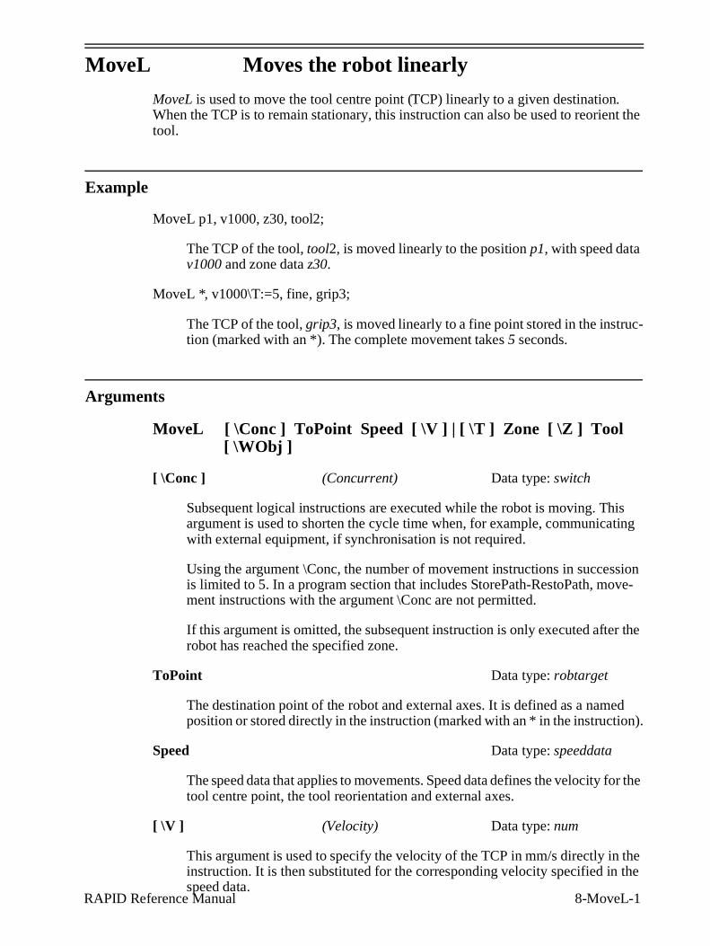
MoveL is used to move the tool centre point (TCP) linearly to a given destination. When the TCP is to remain stationary, this instruction can also be used to reorient the tool.
Example
MoveL p1, v1000, z30, tool2;
The TCP of the tool, tool2, is moved linearly to the position p1, with speed data v1000 and zone data z30.
MoveL *, v1000\T:=5, fine, grip3;
The TCP of the tool, grip3, is moved linearly to a fine point stored in the instruc-tion (marked with an *). The complete movement takes 5 seconds.
Arguments
MoveL [ \Conc ] ToPoint Speed [ \V ] | [ \T ] Zone [ \Z ] Tool [ \WObj ]
[ \Conc ] (Concurrent) Data type: switch
Subsequent logical instructions are executed while the robot is moving. This argument is used to shorten the cycle time when, for example, communicating with external equipment, if synchronisation is not required.
Using the argument \Conc, the number of movement instructions in succession is limited to 5. In a program section that includes StorePath-RestoPath, move-ment instructions with the argument \Conc are not permitted.
If this argument is omitted, the subsequent instruction is only executed after the robot has reached the specified zone.
ToPoint Data type: robtarget
The destination point of the robot and external axes. It is defined as a named position or stored directly in the instruction (marked with an * in the instruction).
Speed Data type: speeddata
The speed data that applies to movements. Speed data defines the velocity for the tool centre point, the tool reorientation and external axes.
[ \V ] (Velocity) Data type: num
This argument is used to specify the velocity of the TCP in mm/s directly in the instruction. It is then substituted for the corresponding velocity specified in the speed data.
8-MoveL-2 RAPID Reference Manual
[ \T ] (Time) Data type: num
This argument is used to specify the total time in seconds during which the robot moves. It is then substituted for the corresponding speed data.
Zone Data type: zonedata
Zone data for the movement. Zone data describes the size of the generated corner path.
[ \Z ] (Zone) Data type: num
This argument is used to specify the position accuracy of the robot TCP directly in the instruction. The length of the corner path is given in mm, which is substi-tuted for the corresponding zone specified in the zone data.
Tool Data type: tooldata
The tool in use when the robot moves. The tool centre point is the point moved to the specified destination position.
[ \WObj] (Work Object) Data type: wobjdata
The work object (coordinate system) to which the robot position in the instruction is related.
This argument can be omitted, and if it is, the position is related to the world coor-dinate system. If, on the other hand, a stationary tool or coordinated external axes are used, this argument must be specified in order to perform a linear movement relative to the work object.
Program execution
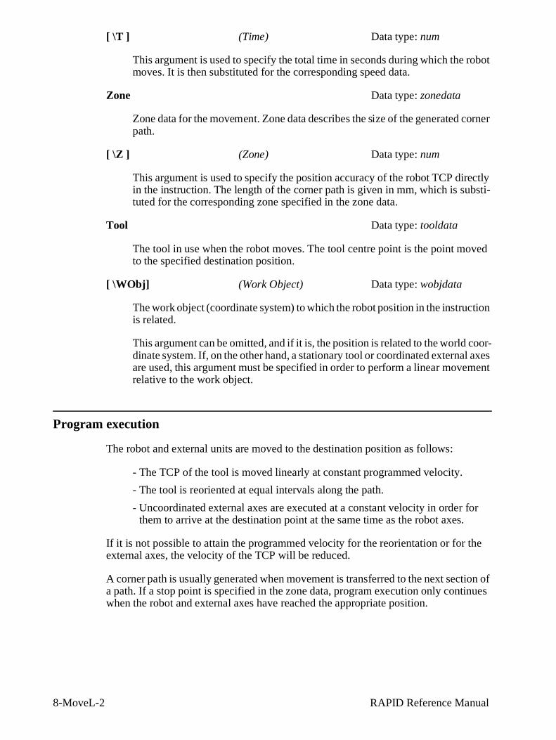
The robot and external units are moved to the destination position as follows:
- The TCP of the tool is moved linearly at constant programmed velocity.
- The tool is reoriented at equal intervals along the path.
- Uncoordinated external axes are executed at a constant velocity in order for them to arrive at the destination point at the same time as the robot axes.
If it is not possible to attain the programmed velocity for the reorientation or for the external axes, the velocity of the TCP will be reduced.
A corner path is usually generated when movement is transferred to the next section of a path. If a stop point is specified in the zone data, program execution only continues when the robot and external axes have reached the appropriate position.
RAPID Reference Manual 8-MoveL-3
Examples
MoveL *, v2000 \V:=2200, z40 \Z:=45, grip3;
The TCP of the tool, grip3, is moved linearly to a position stored in the instruc-tion. The movement is carried out with data set to v2000 and z40; the velocity and zone size of the TCP are 2200 mm/s and 45 mm respectively.
MoveL \Conc, *, v2000, z40, grip3;
The TCP of the tool, grip3, is moved linearly to a position stored in the instruc-tion. Subsequent logical instructions are executed while the robot moves.
MoveL start, v2000, z40, grip3 \WObj:=fixture;
The TCP of the tool, grip3, is moved linearly to a position, start. This position is specified in the object coordinate system for fixture.
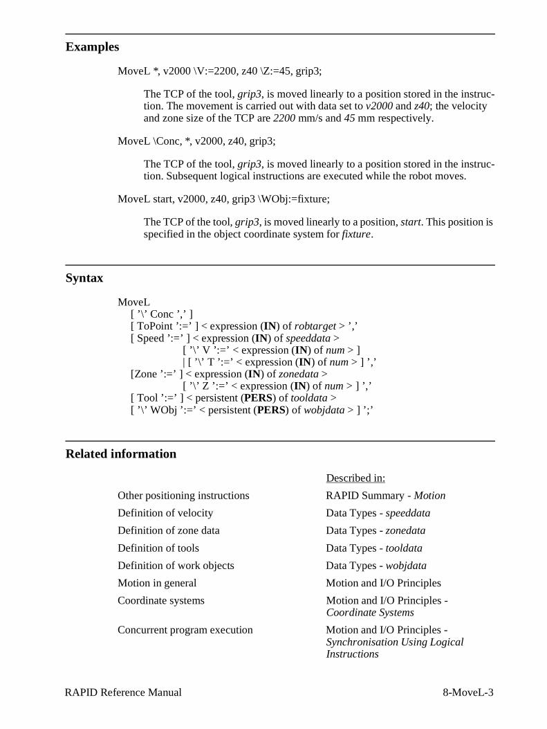
Syntax
MoveL [ ’\’ Conc ’,’ ][ ToPoint ’:=’ ] < expression (IN ) of robtarget > ’,’[ Speed ’:=’ ] < expression (IN ) of speeddata >
[ ’\’ V ’:=’ < expression (IN ) of num > ] | [ ’\’ T ’:=’ < expression (IN ) of num > ] ’,’
[Zone ’:=’ ] < expression (IN ) of zonedata >[ ’\’ Z ’:=’ < expression (IN ) of num > ] ’,’
[ Tool ’:=’ ] < persistent (PERS) of tooldata > [ ’\’ WObj ’:=’ < persistent (PERS) of wobjdata > ] ’;’
Related information
Described in:
Other positioning instructions RAPID Summary - Motion
Definition of velocity Data Types - speeddata
Definition of zone data Data Types - zonedata
Definition of tools Data Types - tooldata
Definition of work objects Data Types - wobjdata
Motion in general Motion and I/O Principles
Coordinate systems Motion and I/O Principles - Coordinate Systems
Concurrent program execution Motion and I/O Principles - Synchronisation Using Logical Instructions
Program Examples Simple Material Handling
User’s Guide 17-3
1 Simple Material Handling
1.1 What the robot does
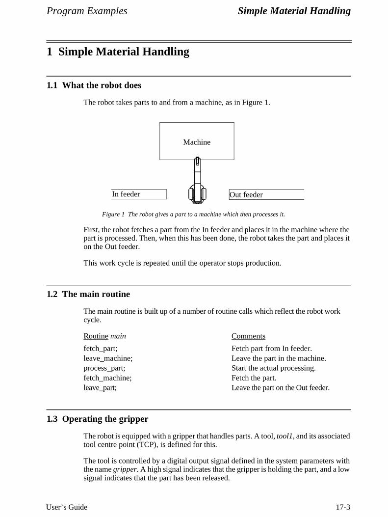
The robot takes parts to and from a machine, as in Figure 1.
Figure 1 The robot gives a part to a machine which then processes it.
First, the robot fetches a part from the In feeder and places it in the machine where the part is processed. Then, when this has been done, the robot takes the part and places it on the Out feeder.
This work cycle is repeated until the operator stops production.
1.2 The main routine
The main routine is built up of a number of routine calls which reflect the robot work cycle.
Routine main Comments
fetch_part; Fetch part from In feeder.leave_machine; Leave the part in the machine.process_part; Start the actual processing.fetch_machine; Fetch the part.leave_part; Leave the part on the Out feeder.
1.3 Operating the gripper
The robot is equipped with a gripper that handles parts. A tool, tool1, and its associated tool centre point (TCP), is defined for this.
The tool is controlled by a digital output signal defined in the system parameters with the name gripper. A high signal indicates that the gripper is holding the part, and a low signal indicates that the part has been released.
Machine
In feeder Out feeder
Simple Material Handling Program Examples
17-4 User’s Guide
In addition, a load data, load1, is defined which describes the load held by the gripper. The best possible motion performance is achieved if the correct load is always specified.
As the gripper grips and releases parts several times during the course of the program, it is best to set up separate routines for this which can be called by the program.
Routine grip Comments
Set gripper; Grip the part.WaitTime 0.3; Wait 0.3 s.GripLoad load1; Specify that there is a load in
the gripper.
Routine release Comments
Reset gripper; Release the part.WaitTime 0.3; Wait 0.3 s.GripLoad LOAD0; Specify that there is no load in
the gripper
1.4 Fetching a part from the In feeder
A part is fetched from the In feeder. As the robot cannot go straight from the previous position (Out feeder), it performs a joint movement to the first position. Then, it uses linear movement to achieve good path accuracy.
Routine fetch_part Comments
MoveJ *, vmax, z50, tool1; Go quickly to position near In feeder.MoveL *, v1000, z30, tool1; Go to position above part.MoveL *, v200, fine, tool1; Go slowly to grip position.grip; Grip part.MoveL *, v200, z30, tool1; Go to position above part.
1.5 Leaving the part in the machine
The robot leaves the part in the machine and then leaves that area so that the machine can be started.
Routine leave_machine Comments
MoveJ *, vmax, z50, tool1; Go quickly to position outsidemachine.
MoveL *, v500, z10, tool1; Go to machine.MoveL *, v200, fine, tool1; Go to leave position.release; Release part.MoveL *, v200, z30, tool1; Go to position above part.MoveL *, v500, z30, tool1; Go to position above machine.
Program Examples Simple Material Handling
User’s Guide 17-5
1.6 Starting to process
Processing starts when the robot pulses an output, do1. Then, using the input di1, the machine informs the robot that the part has been processed and can be fetched.
Routine process_part Comments
PulseDO do1; Pulse output to start machine.WaitDI di1, 1; Wait for the ready signal.
1.7 Fetching the part from the machine
The robot fetches the part from the machine.
Routine fetch_machine Comments
MoveL *, v500, z10, tool1; Go to machine.MoveL *, v200, fine, tool1; Go to fetch position.grip; Grip part.MoveL *, v200, z30, tool1; Go to position above part.MoveL *, v500, z30, tool1; Go to position outside machine.
1.8 Leaving the part on the Out feeder
The robot leaves the part on the Out feeder.
Routine leave_part Comments
MoveJ *, vmax, z30, tool1; Go quickly to position near Out feeder.MoveL *, v500, z30, tool1; Go to position above part.MoveL *, v200, fine, tool1; Go slowly to leave position.release; Release part.MoveL *, v200, z30, tool1; Go to position above part.
Program Examples Material Handling
User’s Guide 17-7
2 Material Handling
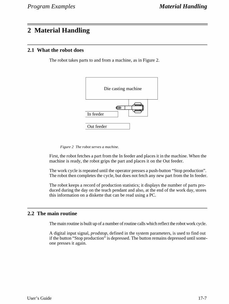
2.1 What the robot does
The robot takes parts to and from a machine, as in Figure 2.
Figure 2 The robot serves a machine.
First, the robot fetches a part from the In feeder and places it in the machine. When the machine is ready, the robot grips the part and places it on the Out feeder.
The work cycle is repeated until the operator presses a push-button “Stop production”. The robot then completes the cycle, but does not fetch any new part from the In feeder.
The robot keeps a record of production statistics; it displays the number of parts pro-duced during the day on the teach pendant and also, at the end of the work day, stores this information on a diskette that can be read using a PC.
2.2 The main routine
The main routine is built up of a number of routine calls which reflect the robot work cycle.
A digital input signal, prodstop, defined in the system parameters, is used to find out if the button “Stop production” is depressed. The button remains depressed until some-one presses it again.
Die casting machine
In feeder
Out feeder
Material Handling Program Examples
17-8 User’s Guide
Routine main Comments
start_production; Initialise production for the day.WHILE Dinput(prodstop) = 0 DO Repeat the cycle until the button
is pressed.fetch_part; Fetch the part from In feeder.leave_machine; Leave part in the machine.process_part; Start the actual processing.fetch_machine; Fetch the part.leave_part; Leave the part on Out feeder.update_cycle; Update operating statistics.
ENDWHILEstop_production; Stop production for the day.
The routines process_part, fetch_machine and leave_part are not included in this example.
2.3 Operating the gripper
A tool, gripper1, defines the TCP and the weight of the gripper. This tool data is defined in the system module USER. In this way, the tool is always present in memory irrespective of which program is loaded.
The gripper is controlled by electric, bistable air valves, which means that there is one signal that controls the grip action and another that controls the release. The names of the signals are defined in the system parameters as grip1 and release1. There is also a signal, gripok, that is high if a part is held by the gripper. This signal is used to check if the gripper has gripped a part correctly.
A load data, payload, is defined which describes the load held by the gripper. The best possible motion performance is achieved if the correct load is always specified.
As the gripper grips and releases parts several times during the course of the program, it is best to set up separate routines for this which can be called by the program. For example:
Routine grip_part Comments
Reset release1;Set grip1; Grip the part.WaitTime 0.5; Wait 0.5 s.IF DInput(gripok)=0 THEN If error (no part in the gripper) ...
TPWrite "ERROR: No part in the gripper"; Write error message on teach pendant.EXIT; Exit program execution.
ENDIFGripLoad payload; Specify that there is a load.
The routine release_part is not included in this example.
Program Examples Material Handling
User’s Guide 17-9
2.4 Starting production
Before the actual production is started, the counter (reg1), which counts the number of parts that are produced during the day, is set to zero. The robot also goes into a home position.
Routine start_production Comments
reg1 := 0; Reset the counter.MoveJ home, v500, fine, gripper1; Go to home position.
In this example, all positions (e.g. home or p1) are named. They are stored as separate position data and can thus be reused in subsequent instructions. However, it is often just as easy to store the positions directly in the instructions (indicated by * in the instruction).
2.5 Fetching the part from the In feeder
Before fetching a part, the robot must check if there is any part to fetch. It does this by means of a photocell (via the feeder signal). This informs the robot if there is a part in position or not. If there is no part, the operator is sent a message and must first correct the error before starting program execution again.
Routine fetch_part Comments
WHILE DInput(feeder) = 0 DO Check if there is any part to fetch.TPErase; If not: Clear the teach pendant and TPWrite "ERROR: No part on feeder"; write error message. Then wait until TPWrite ""; the start signal is given by the opera-
tor.TPReadFK reg2, "Put part on feeder and press start", "Start", "", "","","";
ENDWHILEMoveJ p1, vmax, z50, gripper1; Go quickly to position above part.MoveL p2, v100, fine, gripper1; Go to grip position.grip_part; Grip part.MoveL p1, v200, z30, gripper1; Go to position above part.
2.6 Leaving the part in the machine
The robot leaves the part in the machine and then leaves that area so that the machine can be started. Often, the robot and the machine communicate with one another to check such things as whether the machine is open. This check is not included in the following example.
Material Handling Program Examples
17-10 User’s Guide
Routine leave_machine Comments
MoveJ p3, vmax, z50, gripper1; Go quickly to position outside machine.
MoveL p4, v500, z10, gripper1; Go in to machine.MoveL p5, v100, fine, gripper1; Go to release position.release_part; Release part.MoveL p4, v200, z30, gripper1; Go to position above part.MoveL p3, v500, z50, gripper1; Go to position outside machine.
2.7 Updating operating statistics
The number of parts produced during the day is written on the teach pendant display.
Routine update_cycle Comments
reg1 := reg1 +1; Increment produced parts.TPErase; Clear the display.TPWrite ""; A few blank lines.TPWrite "";TPWrite "No of produced parts = " \Num:=reg1; The number of parts.
2.8 Stopping production for the day
If the operator presses “Stop production” and the robot has completed a work cycle, the robot goes to home position. In addition, the production figures for the day (the day’s date followed by the number of parts produced) are written on diskette.
Routine stop_production Comments
MoveJ home, v500, fine, gripper1; Go to home position.Open "flp1:" \File:="logfile.doc", file\Append; Open the file for writing.Write file, CDate() \Num:=reg1; Write to the file.Close file; Close the file.Stop; Stop program execution.
Before a file can be opened, the data, file, must be created by the type iodev. The real name of the file is logfile.doc.
RAPID Reference Manual 8-TPErase-1
TPErase Erases text printed on the teach pendant
TPErase (Teach Pendant Erase) is used to clear the display of the teach pendant.
Example
TPErase;TPWrite "Execution started";
The teach pendant display is cleared before Execution started is written.
Program execution
The teach pendant display is completely cleared of all text. The next time text is writ-ten, it will be entered on the uppermost line of the display.
Syntax
TPErase;
Related information
Described in:
Writing on the teach pendant RAPID Summary - Communication
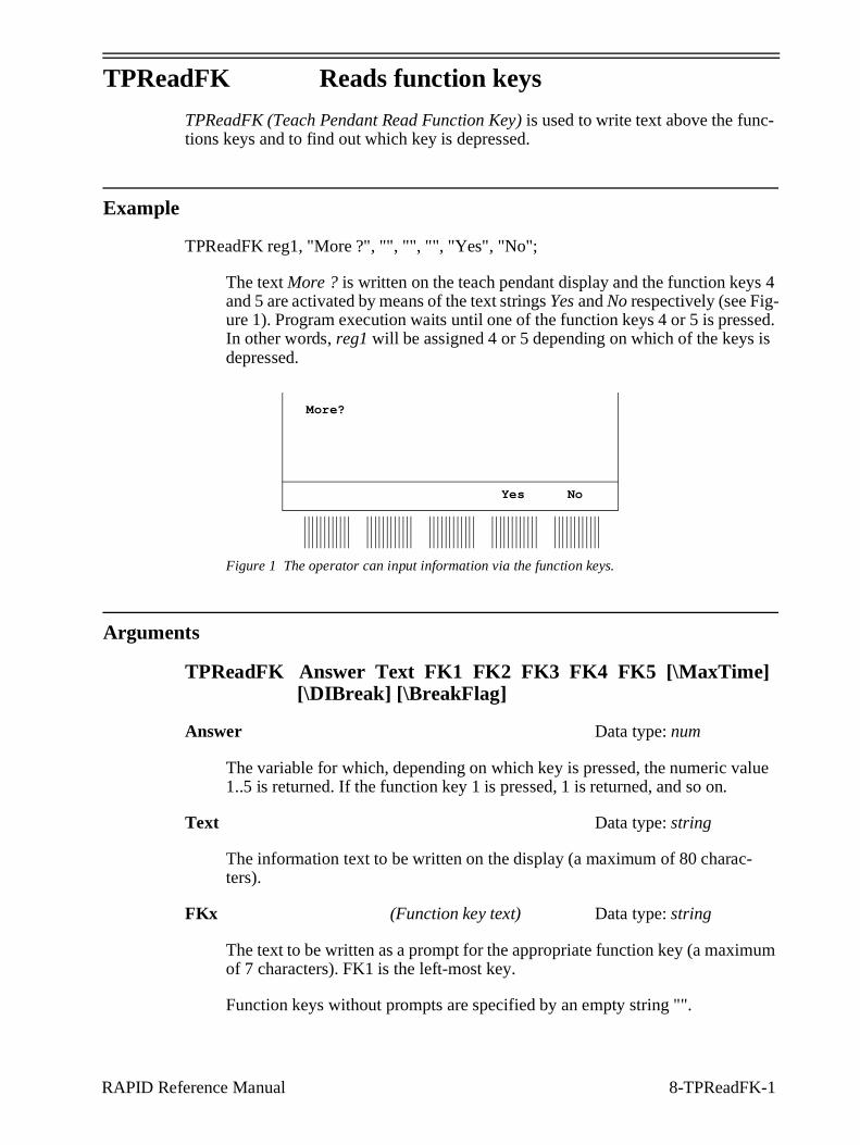
RAPID Reference Manual 8-TPReadFK-1
TPReadFK Reads function keys
TPReadFK (Teach Pendant Read Function Key) is used to write text above the func-tions keys and to find out which key is depressed.
Example
TPReadFK reg1, "More ?", "", "", "", "Yes", "No";
The text More ? is written on the teach pendant display and the function keys 4 and 5 are activated by means of the text strings Yes and No respectively (see Fig-ure 1). Program execution waits until one of the function keys 4 or 5 is pressed. In other words, reg1 will be assigned 4 or 5 depending on which of the keys is depressed.
Figure 1 The operator can input information via the function keys.
Arguments
TPReadFK Answer Text FK1 FK2 FK3 FK4 FK5 [\MaxTime][\DIBreak] [\BreakFlag]
Answer Data type: num
The variable for which, depending on which key is pressed, the numeric value 1..5 is returned. If the function key 1 is pressed, 1 is returned, and so on.
Text Data type: string
The information text to be written on the display (a maximum of 80 charac-ters).
FKx (Function key text) Data type: string
The text to be written as a prompt for the appropriate function key (a maximum of 7 characters). FK1 is the left-most key.
Function keys without prompts are specified by an empty string "".
Yes No
More?
8-TPReadFK-2 RAPID Reference Manual
[\MaxTime] Data type: num
The maximum amount of time [s] that program execution waits. If no function key is depressed within this time, the program continues to execute in the error handler unless the BreakFlag is used (see below). The constant ERR_TP_MAXTIME can be used to test whether or not the maximum time has elapsed.
[\DIBreak] (Digital Input Break) Data type: signaldi
The digital signal that may interrupt the operator dialog. If no function key is depressed when the signal is set to 1 (or is already 1), the program continues to execute in the error handler, unless the BreakFlag is used (see below). The con-stant ERR_TP_DIBREAK can be used to test whether or not this has occurred.
[\BreakFlag] Data type: errnum
A variable that will hold the error code if maxtime or dibreak is used. If this optional variable is omitted, the error handler will be executed. The constants ERR_TP_MAXTIME and ERR_TP_ DIBREAK can be used to select the reason.
Program execution
The information text is always written on a new line. If the display is full of text, this body of text is moved up one line first. Strings longer than the width of the teach pendant (40 characters) are split into two lines.
Prompts are written above the appropriate function keys. Keys without prompts are deactivated.
Program execution waits until one of the activated function keys is depressed.
Example
VAR errnum errvar;...TPReadFK reg1, "Go to service position?", "", "", "", "Yes", "No" \MaxTime:= 600
\DIBreak:= di5\BreakFlag:= errvar;IF reg1 = 4 or OR errvar = ERR_TP_DIBREAK THEN
MoveL service, v500, fine, tool1;Stop;
END IFIF errvar = ERR_TP_MAXTIME EXIT;
The robot is moved to the service position if the forth function key ("Yes") is pressed, or if the input 5 is activated. If no answer is given within 10 minutes, the execution is terminated.
RAPID Reference Manual 8-TPReadFK-3
Syntax
TPReadFK [Answer’:=’] <var or pers (INOUT ) of num>’,’[Text’:=’] <expression (IN ) of string>’,’[FK1 ’:=’] <expression (IN ) of string>’,’ [FK2 ’:=’] <expression (IN ) of string>’,’[FK3 ’:=’] <expression (IN ) of string>’,’ [FK4 ’:=’] <expression (IN ) of string>’,’[FK5 ’:=’] <expression (IN ) of string>[’\’MaxTime ’:=’ <expression (IN ) of num>][’\’DIBreak ’:=’ <variable (VAR ) of signaldi>] [’\’BreakFlag ’:=’ <var or pers (INOUT ) of errnum>]’;’
Related information
Described in:
Writing to and reading from RAPID Summary - Communicationthe teach pendant
Replying via the teach pendant Running Production
RAPID Reference Manual 8-TPReadNum-1
TPReadNum Reads a number from the teach pendant
TPReadNum (Teach Pendant Read Numerical) is used to read a number from the teach pendant.
Example
TPReadNum reg1, “How many units should be produced?“;
The text How many units should be produced? is written on the teach pendant display. Program execution waits until a number has been input from the numeric keyboard on the teach pendant. That number is stored in reg1.
Arguments
TPReadNum Answer String [\MaxTime] [\DIBreak][\BreakFlag]
Answer Data type: num
The variable for which the number input via the teach pendant is returned.
String Data type: string
The information text to be written on the teach pendant (a maximum of 80 char-acters).
[\MaxTime] Data type: num
The maximum amount of time that program execution waits. If no number is input within this time, the program continues to execute in the error handler unless the BreakFlag is used (see below). The constant ERR_TP_MAXTIME can be used to test whether or not the maximum time has elapsed.
[\DIBreak] (Digital Input Break) Data type: signaldi
The digital signal that may interrupt the operator dialog. If no number is input when the signal is set to 1 (or is already 1), the program continues to execute in the error handler unless the BreakFlag is used (see below). The constant ERR_TP_DIBREAK can be used to test whether or not this has occurred.
[\BreakFlag] Data type: errnum
A variable that will hold the error code if maxtime or dibreak is used. If this optional variable is omitted, the error handler will be executed.The constants ERR_TP_MAXTIME and ERR_TP_ DIBREAK can be used to select the reason.
8-TPReadNum-2 RAPID Reference Manual
Program execution
The information text is always written on a new line. If the display is full of text, this body of text is moved up one line first. Strings longer than the width of the teach pen-dant (40 characters) are split into two lines.
Program execution waits until a number is typed on the numeric keyboard (followed by Enter or OK).
Example
TPReadNum reg1, “How many units should be produced?“;FOR i FROM 1 TO reg1 DO
produce_part;ENDFOR
The text How many units should be produced? is written on the teach pendant display. The routine produce_part is then repeated the number of times that is input via the teach pendant.
Syntax
TPReadNum [Answer’:=’] <var or pers (INOUT ) of num>’,’[String’:=’] <expression (IN ) of string>[’\’MaxTime ’:=’ <expression (IN ) of num>][’\’DIBreak ’:=’ <variable (VAR ) of signaldi>][’\’BreakFlag ’:=’ <var or pers (INOUT ) of errnum>] ’;’
Related information
Described in:
Writing to and reading from RAPID Summary - Communicationthe teach pendant
Entering a number on the teach pendant Production Running
Examples of how to use the arguments Instructions - TPReadFKMaxTime, DIBreak and BreakFlag
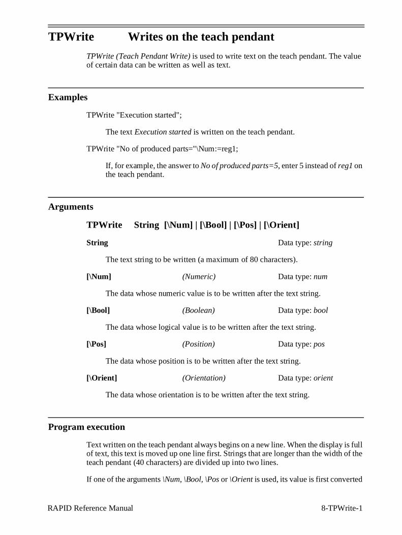
RAPID Reference Manual 8-TPWrite-1
TPWrite Writes on the teach pendant
TPWrite (Teach Pendant Write) is used to write text on the teach pendant. The value of certain data can be written as well as text.
Examples
TPWrite "Execution started";
The text Execution started is written on the teach pendant.
TPWrite "No of produced parts="\Num:=reg1;
If, for example, the answer to No of produced parts=5, enter 5 instead of reg1 on the teach pendant.
Arguments
TPWrite String [\Num] | [\Bool] | [\Pos] | [\Orient]
String Data type: string
The text string to be written (a maximum of 80 characters).
[\Num] (Numeric) Data type: num
The data whose numeric value is to be written after the text string.
[\Bool] (Boolean) Data type: bool
The data whose logical value is to be written after the text string.
[\Pos] (Position) Data type: pos
The data whose position is to be written after the text string.
[\Orient] (Orientation) Data type: orient
The data whose orientation is to be written after the text string.
Program execution
Text written on the teach pendant always begins on a new line. When the display is full of text, this text is moved up one line first. Strings that are longer than the width of the teach pendant (40 characters) are divided up into two lines.
If one of the arguments \Num, \Bool, \Pos or \Orient is used, its value is first converted
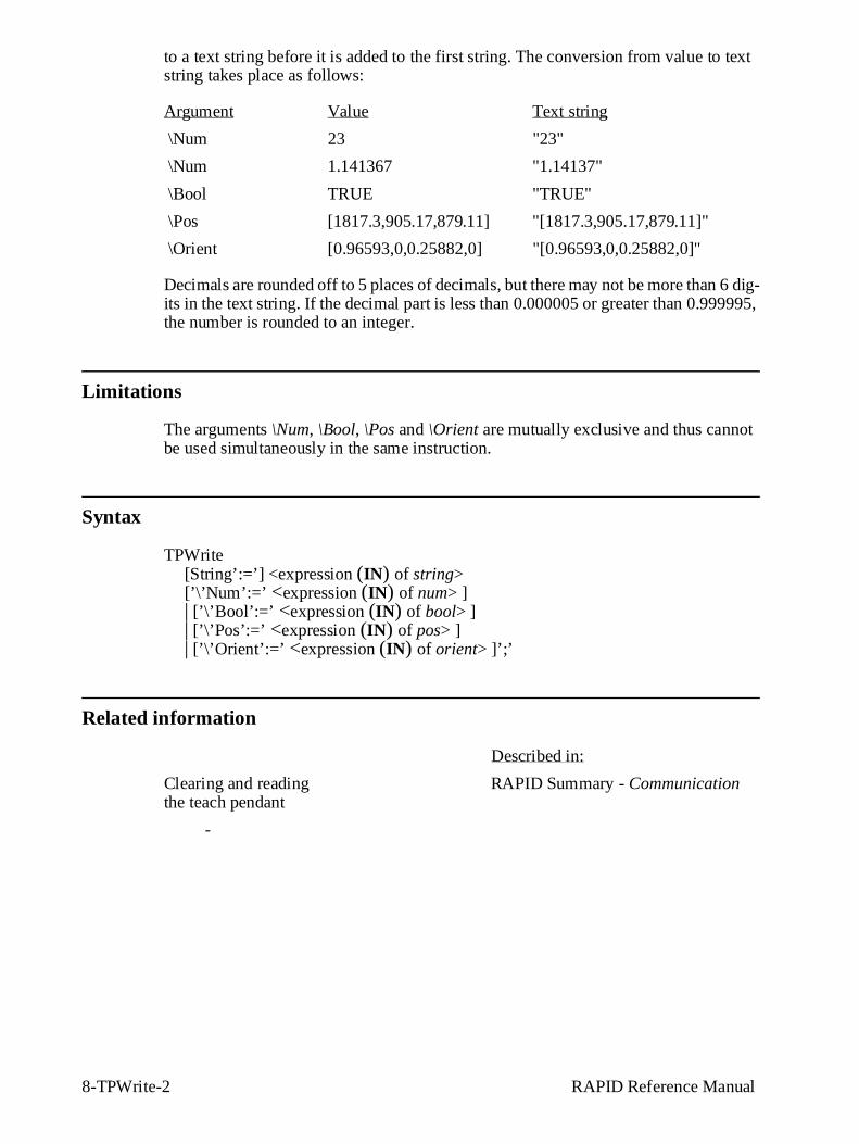
8-TPWrite-2 RAPID Reference Manual
to a text string before it is added to the first string. The conversion from value to text string takes place as follows:
Argument Value Text string
\Num 23 "23"
\Num 1.141367 "1.14137"
\Bool TRUE "TRUE"
\Pos [1817.3,905.17,879.11] "[1817.3,905.17,879.11]"
\Orient [0.96593,0,0.25882,0] "[0.96593,0,0.25882,0]"
Decimals are rounded off to 5 places of decimals, but there may not be more than 6 dig-its in the text string. If the decimal part is less than 0.000005 or greater than 0.999995, the number is rounded to an integer.
Limitations
The arguments \Num, \Bool, \Pos and \Orient are mutually exclusive and thus cannot be used simultaneously in the same instruction.
Syntax
TPWrite[String’:=’] <expression (IN) of string> [’\’Num’:=’ <expression (IN) of num> ] | [’\’Bool’:=’ <expression (IN) of bool> ] | [’\’Pos’:=’ <expression (IN) of pos> ] | [’\’Orient’:=’ <expression (IN) of orient> ]’;’
Related information
Described in:
Clearing and reading RAPID Summary - Communicationthe teach pendant
-
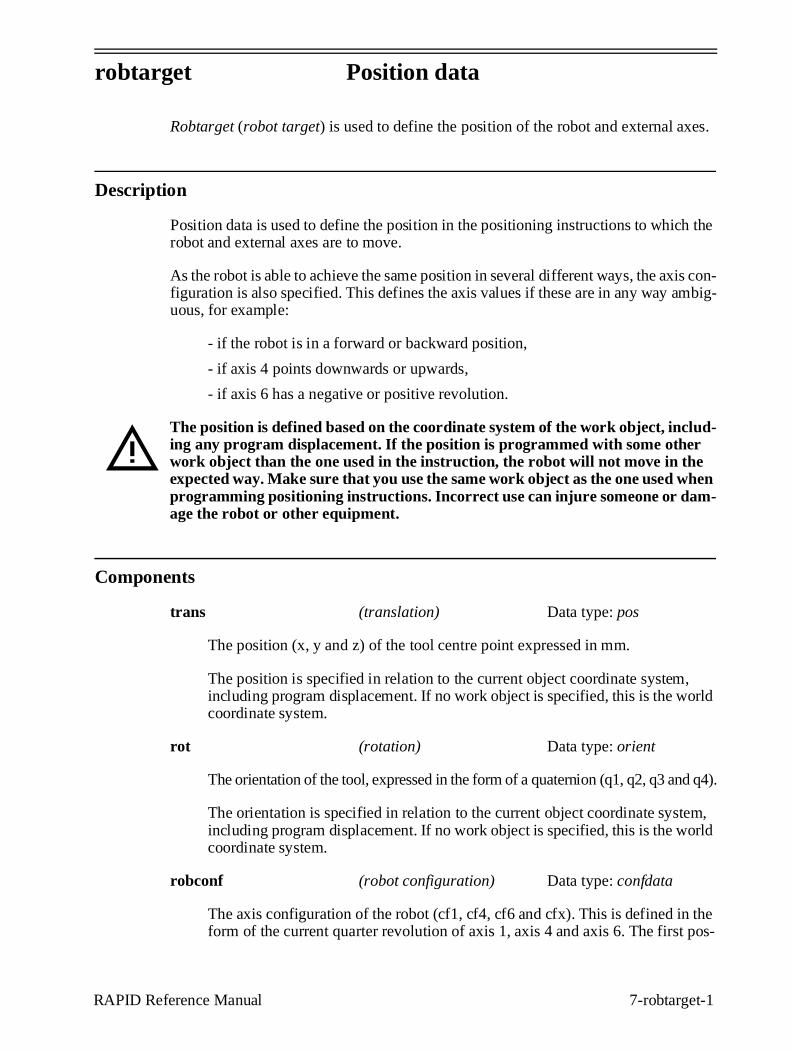
yp g
RAPID Reference Manual 7-robtarget-1
robtarget Position data
Robtarget (robot target) is used to define the position of the robot and external axes.
Description
Position data is used to define the position in the positioning instructions to which the robot and external axes are to move.
As the robot is able to achieve the same position in several different ways, the axis con-figuration is also specified. This defines the axis values if these are in any way ambig-uous, for example:
- if the robot is in a forward or backward position,
- if axis 4 points downwards or upwards,
- if axis 6 has a negative or positive revolution.
The position is defined based on the coordinate system of the work object, includ-ing any program displacement. If the position is programmed with some other work object than the one used in the instruction, the robot will not move in the expected way. Make sure that you use the same work object as the one used when programming positioning instructions. Incorrect use can injure someone or dam-age the robot or other equipment.
Components
trans (translation) Data type: pos
The position (x, y and z) of the tool centre point expressed in mm.
The position is specified in relation to the current object coordinate system, including program displacement. If no work object is specified, this is the world coordinate system.
rot (rotation) Data type: orient
The orientation of the tool, expressed in the form of a quaternion (q1, q2, q3 and q4).
The orientation is specified in relation to the current object coordinate system, including program displacement. If no work object is specified, this is the world coordinate system.
robconf (robot configuration) Data type: confdata
The axis configuration of the robot (cf1, cf4, cf6 and cfx). This is defined in the form of the current quarter revolution of axis 1, axis 4 and axis 6. The first pos-
g yp
7-robtarget-2 RAPID Reference Manual
itive quarter revolution 0-90 o is defined as 0. The component cfx is not used at present.
For more information, see data type confdata.
extax (external axes) Data type: extjoint
The position of the external axes.
The position is defined as follows for each individual axis (eax_a, eax_b ... eax_f):
- For rotating axes, the position is defined as the rotation in degrees from the cal-ibration position.
- For linear axes, the position is defined as the distance in mm from the calibra-tion position.
External axes eax_a ... are logical axes. How the logical axis number and the physical axis number are related to each other is defined in the system parame-ters.
The value 9E9 is defined for axes which are not connected. If the axes defined in the position data differ from the axes that are actually connected on program exe-cution, the following applies:
- If the position is not defined in the position data (value 9E9), the value will be ignored, if the axis is connected and not activated. But if the axis is activated, it will result in an error.
- If the position is defined in the position data although the axis is not connected, the value is ignored.
Examples
CONST robtarget p15 := [ [600, 500, 225.3], [1, 0, 0, 0], [1, 1, 0, 0],[ 11, 12.3, 9E9, 9E9, 9E9, 9E9] ];
A position p15 is defined as follows:
- The position of the robot: x = 600, y = 500 and z = 225.3 mm in the object coor-dinate system.
- The orientation of the tool in the same direction as the object coordinate system.
- The axis configuration of the robot: axes 1 and 4 in position 90-180o, axis 6 in position 0-90o.
- The position of the external logical axes, a and b, expressed in degrees or mm (depending on the type of axis). Axes c to f are undefined.
yp g
RAPID Reference Manual 7-robtarget-3
VAR robtarget p20;. . .p20 := CRobT();p20 := Offs(p20,10,0,0);
The position p20 is set to the same position as the current position of the robot by call-ing the function CRobT. The position is then moved 10 mm in the x-direction.
Limitations
When using the configurable edit function Absolute Limit Modpos, the number of char-acters in the name of the data of the type robtarget, is limited to 14 (in other cases 16).
Structure
< dataobject of robtarget >< trans of pos >
< x of num >< y of num >< z of num >
< rot of orient >< q1 of num >< q2 of num >< q3 of num >< q4 of num >
< robconf of confdata >< cf1 of num >< cf4 of num >< cf6 of num >< cfx of num >
< extax of extjoint >< eax_a of num >< eax_b of num >< eax_c of num >< eax_d of num >< eax_e of num >< eax_f of num >