Embed Size (px)
Citation preview
FACULDADE DE ENGENHARIA DA UNIVERSIDADE DO PORTO
Humanizing Robot Dance Movements
Paulo Sousa
Master in Informatics and Computing Engineering
Supervisor: Luis Paulo Reis Ph.D
Second Supervisor: Fabien Gouyon Ph.D
Co-Supervisor: João Lobato Oliveira MSc.
18st July, 2011

Humanizing Robot Dance Movements
Paulo Sousa
Master in Informatics and Computing Engineering
Approved in oral examination by the committee:
Chair: António Fernando Vasconcelos Cunha Castro Coelho (Ph.D)
External Examiner: Luis Miguel Parreira Correia (Ph.D)
Supervisor: Luis Paulo Gonçalves dos Reis (Ph.D)
18st July, 2011

Abstract
Robotic applications are increasing in a daily basis. Robots can and will be able to per-form from simple day-life routines to complicated actions. There is, so, an increasing needof achieving a more complete and meaningful interaction between human and robots. Hu-man interaction recurs to body motion as a form of communication and expression, andas such it presents a good field to exploit in order to improve humanoid robots.
Expressiveness and naturalness in robotic motions and behaviors can be replicatedwith the usage of captured human motion data.
As dance performances present moments of great expressiveness, where emotion andfeelings can be transmitted to the audience by means of complex motion, they can beused as a rich case study and as a vast space of motion to replicate in a humanoid robot.As such, in order to feasibly and easily replicate these type of motions we recurred tocaptured human motion data of Samba dance, properly synchronized to Samba music,previously annotated by experts. Using this, a spatiotemporal representation of the dancemotion was built in relation to the respective musical temporal structure (musical me-ter). This representation presents the variability of the dance space occupation during thedance performance, and its intrinsic musical relation. From this representation key-poseswere synthesized with variability according to the original motion capture human bodymodel, at defined metrical resolutions, by means of random processes calculated with ro-tations between body segments. In order to replicate the dance in the robot, the key-poseswere morphologically resized and the original trajectories were adapted, overcoming therobot’s varied kinematic constraints. From the synthesized and adapted key-poses, jointrotations were extracted to allow the reproduction of these same poses onto the target hu-manoid robot. Key-pose refinement was then applied in order to increase the similarityof the humanoid pose to the original key-poses, by means of Tabu Search optimization.Finally, the resultant robot dance motion was generated by sine-interpolation of the key-poses, at quarter-beat resolution and with variability, and performed at beat-synchronousvelocity, to replicate the original musical relationship.
All the methods used in the process were numerically and visually tested, in termsof pose similarity with the original dance, and valid adaption of the represented bodymorphology. This was performed in order to evaluate the several steps of the process. Fi-nally, an user-survey was also performed for obtaining subjective measures of the evinceddegree of similarity and musical expressiveness between several dance motion excerpts,produced from the several methods. All tests and evaluation where performed on a simu-lated humanoid robot NAO in SimSpark, a generic robotics simulator.
The obtained results present a robot dance motion with a good degree of similaritywith the original dance motion. This similarity was greater in the arms, since the robotarms and the human’s are quite morphologically similar, but it was a bit compromised
i
in the robot’s leg movements, due to especial restrictions on its hip section, which isof higher specific relevance to Samba dance. Ultimately, concerning the evinced degreeof musical expressiveness, the vast majority of the inquired people validated the beat-synchrony of the robot dance performance. Yet, further studies are needed to evaluate theeffect of introducing variability in the overall expressiveness of the resultant dance.
ii
Resumo
As aplicações da robótica aumentam diariamente. Assim, os robôs podem e devem sercapazes de executar variadas acções, desde acções do dia-a-dia até a realização de acçõesmais complexas, complicadas ou delicadas. Portanto, existe uma necessidade de con-seguir uma interacção mais completa e significativa entre humanos e robôs. Se atentar-mos na interacção humana, esta pode ser realizada, ou complementada, por movimentosdo corpo. Logo, dando a possibilidade de um robô humanóide realizar movimentos pare-cidos com os humanos iria melhorar a sua capacidade de interacção com os humanos.A expressividade e naturalidade dos movimentos robóticos podem ser melhoradas pelareplicação de movimentos humanos.
A dança apresenta momentos de grande expressividade, que podem transmitir emoçãoe sentimento para quem assiste, e assim pode ser utilizado como um rico caso de estudooferecendo um basto leque de movimentos a replicar num robô humanóide.
Para este efeito, e de forma a facilmente replicar movimentos de dança em humanóides,recorremos a dados de captura de movimento humanos relativos a dança de samba, estesdados foram sincronizados com a música que havia sido previamente anotada por espe-cialistas. Com esta informação, uma representação espácio-temporal do movimento damúsica foi construída em relação a respectiva estrutura temporal da música. Esta repre-sentação apresenta a variabilidade inerente a uma actuação de dança e representa o espaçoocupado pelo bailarino durante uma actuação. Tendo como base esta representação, poseschaves foram construídas de acordo com o modelo do corpo humano presente nos dadosde captura de movimento. Esta geração das poses foi feita em ciclos métricos definidospor meio da escolha aleatória de rotações entre os segmentos do corpo. De forma areproduzir a dança no robot as poses foram adaptadas morfologicamente, de forma a rep-resentarem o tamanho do robot e a cumprirem as várias restrições físicas do mesmo. Apartir das poses geradas e adaptadas os ângulos entre os vários segmentos do corpo foramextraídos possibilitando a reprodução das poses no robô humanóide. Estas poses foremdepois refinadas de forma a aumentar a similaridade com as originais, para este efeito foiutilizada optimização com base no algoritmo Tabu Search. Finalmente o movimento dedança foi gerado por interpolação das poses, permitindo a execução síncrona do movi-mento de dança.
Todos os métodos utilizados foram testados numericamente e visualmente em relaçãoà similaridade das poses e em relação a correcção da morfologia do corpo utilizado. Com-plementarmente um inquérito foi realizado de forma a obter uma avaliação subjectiva dadança realizada pelo robot. Todos os testes foram realizados com base numa versão sim-ulada do humanóide NAO no ambiente de simulação Simspark.
Os resultados obtidos apresentam um robô a dançar Samba, com similaridade ao movi-mento de dança original. Esta similaridade é maior nos braços, enquanto nas pernas as
iii

diferenças morfológicas na zona da cintura criam algumas diferenças no movimento eimpossibilitam outros movimentos.
iv

Acknowledgements
First and foremost i would like to thank to João Lobato for all the numerous conversations,orientation and advices that he gave me during the work of this thesis. I would also liketo thank Luís Paulo Reis and Fabien Gouyon for the orientation, guidance and help in thisthesis. A special thank to Luís Cruz for the help on the understanding of the humanoidNAO and in the help with the optimization framework. And also to everyone that helpedwith advices or conversations over my work. I also thank to everyone that helped in thevisual evaluation of the results at the final stage of this work.
Last but not least, a special thank to my family and girlfriend for all the support,patience and help.
Paulo Sousa
v

vi
Contents
1 Introduction 11.1 Motivation . . . . . . . . . . . . . . . . . . . . . . . . . . . . . . . . . . 1
1.1.1 Applications . . . . . . . . . . . . . . . . . . . . . . . . . . . . 21.2 Goals . . . . . . . . . . . . . . . . . . . . . . . . . . . . . . . . . . . . 21.3 Methodology and Tools . . . . . . . . . . . . . . . . . . . . . . . . . . . 3
1.3.1 Motion Capture and Analysis . . . . . . . . . . . . . . . . . . . 41.3.2 Musical Rhythmic Qualities . . . . . . . . . . . . . . . . . . . . 51.3.3 Kinematics . . . . . . . . . . . . . . . . . . . . . . . . . . . . . 61.3.4 Robotic Platforms and Simulators . . . . . . . . . . . . . . . . . 71.3.5 Optimization . . . . . . . . . . . . . . . . . . . . . . . . . . . . 9
1.4 Research Institutions . . . . . . . . . . . . . . . . . . . . . . . . . . . . 111.5 Thesis Outline . . . . . . . . . . . . . . . . . . . . . . . . . . . . . . . . 11
2 Related Work 132.1 Dance Motion Analysis . . . . . . . . . . . . . . . . . . . . . . . . . . . 132.2 Motion Synthesis and Generation . . . . . . . . . . . . . . . . . . . . . . 17
2.2.1 Computer Animated Systems . . . . . . . . . . . . . . . . . . . 172.2.2 Robotic Systems . . . . . . . . . . . . . . . . . . . . . . . . . . 20
2.3 Humanoid Motion Optimization . . . . . . . . . . . . . . . . . . . . . . 262.4 Conclusions and Proposal . . . . . . . . . . . . . . . . . . . . . . . . . . 27
3 Humanizing Robot Dance Movements 293.1 Dance Motion Analysis . . . . . . . . . . . . . . . . . . . . . . . . . . . 293.2 Key-Poses Synthesis with Variability . . . . . . . . . . . . . . . . . . . . 313.3 Key-Poses Morphological Adaption . . . . . . . . . . . . . . . . . . . . 34
3.3.1 Different Segments Lengths . . . . . . . . . . . . . . . . . . . . 353.3.2 Different Number of Joints . . . . . . . . . . . . . . . . . . . . . 363.3.3 Different DOF . . . . . . . . . . . . . . . . . . . . . . . . . . . 383.3.4 Additional physical restrictions . . . . . . . . . . . . . . . . . . 38
3.4 Key-Poses Retargeting . . . . . . . . . . . . . . . . . . . . . . . . . . . 403.4.1 Calculation of the Upper-Body Joint Rotations . . . . . . . . . . 413.4.2 Calculation of the Lower-Body Joint Rotations . . . . . . . . . . 42
3.5 Key-Poses Refinement . . . . . . . . . . . . . . . . . . . . . . . . . . . 433.6 Robot Motion Generation . . . . . . . . . . . . . . . . . . . . . . . . . . 44
3.6.1 Generating Expressive Robot Dancing Sequences . . . . . . . . . 453.7 Conclusions . . . . . . . . . . . . . . . . . . . . . . . . . . . . . . . . . 46
vii
CONTENTS
4 Experiments and Results 474.1 Key-Poses synthesis based on random angles . . . . . . . . . . . . . . . 484.2 Motion Morphological Adaption . . . . . . . . . . . . . . . . . . . . . . 51
4.2.1 Different Segments Lengths . . . . . . . . . . . . . . . . . . . . 514.2.2 Different Number of Joints . . . . . . . . . . . . . . . . . . . . . 524.2.3 Additional physical restrictions . . . . . . . . . . . . . . . . . . 53
4.3 Key-Poses Retargeting . . . . . . . . . . . . . . . . . . . . . . . . . . . 554.4 Key-Poses Refinement . . . . . . . . . . . . . . . . . . . . . . . . . . . 584.5 Subjective Evaluation . . . . . . . . . . . . . . . . . . . . . . . . . . . . 594.6 Discussion . . . . . . . . . . . . . . . . . . . . . . . . . . . . . . . . . . 65
4.6.1 Key-Pose Synthesis with Variability . . . . . . . . . . . . . . . . 654.6.2 Key-Poses Morphological Adaption . . . . . . . . . . . . . . . . 654.6.3 Robot Key-Poses Refinement . . . . . . . . . . . . . . . . . . . 664.6.4 Subjective Evaluation . . . . . . . . . . . . . . . . . . . . . . . . 67
5 Conclusion and Future Work 695.1 Conclusion . . . . . . . . . . . . . . . . . . . . . . . . . . . . . . . . . 695.2 Future Work . . . . . . . . . . . . . . . . . . . . . . . . . . . . . . . . . 70
References 73
A Subjective Evaluation: Inquiry 77
viii
List of Figures
1.1 Illustration of the hierarchical musical rhythmic metrical-levels [Kla03]. . 51.2 (a) Hierarchical representation of meter structure. Each hierarchical met-
ric level is then subdivided, or grouped, in other levels. (b) Spatiotempo-ral representation of metric accents in a dance gesture with a period of 2beats. [ONG+11] . . . . . . . . . . . . . . . . . . . . . . . . . . . . . . 6
1.3 Body planes positions relative the human body. [Hea] . . . . . . . . . . 71.4 Humanoid robot NAO. a) Real robot. middle) Simulated robot. right)
Kinematic body model description. . . . . . . . . . . . . . . . . . . . . 81.5 Example of a simple Slot Behavior. . . . . . . . . . . . . . . . . . . . . 9
2.1 MoCap dance motion analysis [SNI06a]: a) Simple human body model(right); b) Extracted motion features (left). . . . . . . . . . . . . . . . . . 15
2.2 MoCap dance motion analysis [SNI06b]: graph of motion features ac-cording to the hands’ trajectories. . . . . . . . . . . . . . . . . . . . . . . 15
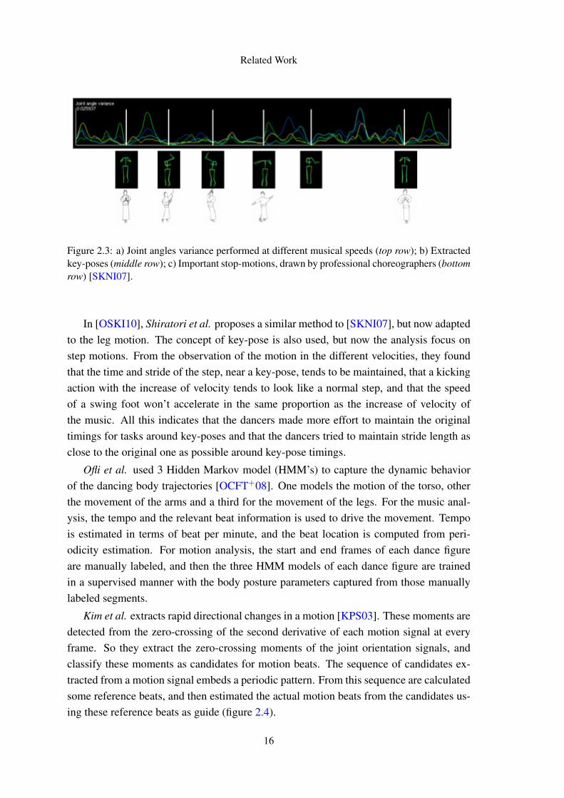
2.3 a) Joint angles variance performed at different musical speeds (top row);b) Extracted key-poses (middle row); c) Important stop-motions, drawnby professional choreographers (bottom row) [SKNI07]. . . . . . . . . . 16
2.4 Estimation of reference motion beats according to joint motion cues, in [KPS03]. 172.5 Overview of the dance motion synthesis algorithm proposed by [SNI06a]. 182.6 Motion Synthesis Algorithm [SNI06b] . . . . . . . . . . . . . . . . . . 192.7 Motion-music correlation as proposed by [SNI06b]. The blue line rep-
resent motion key-frame feature and the red lines shows the music beatfeature. . . . . . . . . . . . . . . . . . . . . . . . . . . . . . . . . . . . 19
2.8 Examples of motions and transitions by the motion graph proposed by [KPS03]. 202.9 Example of the application of the key-pose synthesis method with vari-
ability, for one kinematic chain, starting from joint 11 until the extremity(joint 20) [ONG+10]. . . . . . . . . . . . . . . . . . . . . . . . . . . . . 21
2.10 Consideration of joint limitations in the humanoid upper-body adaptionof the original dance motion [SKNI07]. . . . . . . . . . . . . . . . . . . 21
2.11 Motion Generation algorithms, considering the maintenance of similaritywith the original dance, and biped balance [ZHD+04]: a) Single-supportphase (left); b) Double support phase (right). . . . . . . . . . . . . . . . 23
2.12 Taiji key-poses: comparison of performer (a) and humanoid (b) [ZHD+04]. 242.13 a) MoCap human body model (left); b) Simplified human body model
(right) [KKYO09]. . . . . . . . . . . . . . . . . . . . . . . . . . . . . . 242.14 Algorithm for stable robot pelvis trajectories, in kinematic and dynamic
mapping of human motion onto a humanoid robot [KKYO09]. . . . . . . 25
ix
LIST OF FIGURES
2.15 MAHRU dance: a) Human performance (top row); Humanoid perfor-mance (bottom row) [KKYO09]. . . . . . . . . . . . . . . . . . . . . . . 25
2.16 Humanoid dance motion generation [RNKI05]: a) Comparison of thehand markers between the MoCap body model and the robot (left); b)Exemplar Japanese dance performance (left). . . . . . . . . . . . . . . . 26
3.1 System Architecture. Motion Analysis Architecture [ONG+10] (rigth).Motion Generation: Adaptation and Retargting (left). . . . . . . . . . . . 30
3.2 Projection of musical cues (metric classes) onto the dance trajectories. a)annotation of metric structure of the music is snchronized with the Mo-Cap recording. These cues are projected c) onto the movement vectors (inthe example, right hand movements) as different classes of points (e.g.:1st beat, 2nd beat - receptively described as 1 and 2 in the figure). Finally,the point clouds are discriminated using LDA analysis which guaranteesthe separation of point-clouds. In this study we assumed a spherical dis-tribution for the point clouds whose radius is defined by the average ofthe Euclidean distances from all points of the class to the mean [ONG+11]. 31
3.3 a) A point cloud representation of the left hand trajectories for the con-sidered metrical classes, at quarter-beat resolution; b) Point cloud afterapplying LDA analysis; c) Spherical distributions (one per metrical class)representing the point clouds. [ONG+11] . . . . . . . . . . . . . . . . . 31
3.4 Body joints and kinematic chains (a)). Propagation of stochastic pro-cesses along a kinematic chain (b)). Example of the application of themethod to calculate a random point, for the joint 18 (c)). Calculation ofthe joint 18 position based on random angles (d)). [ONG+11] . . . . . . 34
3.5 Resize method. Resizing of a segment (from T GA1 to T GA2) and trans-lation of the segment target sphere (T GA2). Example of the applianceof the translation, represented by “trans” in the image, to the rest of thekinematic chain (T GA3). . . . . . . . . . . . . . . . . . . . . . . . . . . 36
3.6 Morphological adaption of a kinematic chain with three joints ( j, j+ 1,j + 2) to one with two joints ( j, j + 2), by “erasing” the middle joint:a) A sphere Sm
j , centered in the position of the first joint pmj , with radius
l j, j+2 = l j, j+1 + l j+1, j+2, intersects the spherical distribution of the ex-tremity joint Dm
j+2; b) Smj doesn’t intersects Dm
j+2 requiring a translationof Dm
j+2 towards Dmj , pointed by ~vd . . . . . . . . . . . . . . . . . . . . . 37
3.7 Physical Restriction. Situation where the segment (s) from pmj to a point
in the spherical cap Cmj′ , that results from the interception of must be Sm
jwith Dm
j′ , must be parallel to the segment (s2) from pmj 2 to a point in the
spherical cap Cmj2′ , that results from the interception of must be Sm
j 2 withDm
j2′ . . . . . . . . . . . . . . . . . . . . . . . . . . . . . . . . . . . . . . 39
3.8 a) Considered labels for joints. b) Joint rotation axis and body local co-ordinate axis. c) NAO joint distribution and joint rotation axis (adaptedfrom [Sim]). . . . . . . . . . . . . . . . . . . . . . . . . . . . . . . . . 40
3.9 Key-poses Interpolation (adapted from [ONG+11]. a) Key-poses inter-polation. b) Joint interpolation. . . . . . . . . . . . . . . . . . . . . . . 45
x
LIST OF FIGURES
4.1 Body model segments (represented by ssegmentnumber), joints and kine-matic chains. . . . . . . . . . . . . . . . . . . . . . . . . . . . . . . . . 50
4.2 Visualization of three synthesized key-poses, at “variability-4”, in orderto evaluate if all the calculated joints are inside of their respective TGAspherical distributions. a) Method based on random points (bottom row).b) Method based on random rotations (upper row). . . . . . . . . . . . . 51
4.3 Visual comparison of some key-poses examples synthesized, at “variability-4”, with: method based on random points (black line), method based onrandom rotations (blue line). Joints are represented by a circle. . . . . . . 51
4.4 Key-poses synthesized with variability (at “variability-4”) for differentbody scales (axis measures in mm): a) Original captured human body(left). Body segments scaled 2x (middle). Body segments scaled 0.5x(right). . . . . . . . . . . . . . . . . . . . . . . . . . . . . . . . . . . . . 52
4.5 a) Simulated NAO box model with the respective size of each body part(adapted from [Sim]) (left). b) NAO’s box model with blue lines repre-senting the adopted body model and squares in the considered joints (thesize of the hands was considered equal to the feet) (right). . . . . . . . . . 53
4.6 a) Key-pose generated using body with NAO’s segment lengths (left). b)Key-pose generated using the original MoCap human model (right). . . . 53
4.7 Comparison of a key-pose with the spine middle joint (bottom images)and without the spine middle joint (top images). a) Synthesized key-pose(left); b), c) Detail of the spine joints, with their spherical distributions, indifferent view angles (middle and right). . . . . . . . . . . . . . . . . . . 54
4.8 Comparison of a pose with normal hip segments (top images) and withthe adapted hip segments(bottom images). a) Full pose (left); b) c) Detailof the hip joints, with spherical distributions, in different angles of vision(middle and right). . . . . . . . . . . . . . . . . . . . . . . . . . . . . . 54
4.9 Visualization of key-pose 1 (top) to key-pose 4 (bottom) (each row repre-sents a new pose), synthesized at “variability-4”: a) Synthesized-adjusted(left); b), c) Retargeted to simulated humanoid NAO, in frontal (middle)and lateral (right) views. . . . . . . . . . . . . . . . . . . . . . . . . . . 56
4.10 Visualization of key-pose 5 (top) to key-pose 8 (bottom) (each row repre-sents a new pose), synthesized at “variability-4”: a) Synthesized-adjusted(left); b), c) Retargeted to simulated humanoid NAO, in frontal (middle)and lateral (right) views. . . . . . . . . . . . . . . . . . . . . . . . . . . 57
4.11 Visualization of key-pose 1 (top) to key-pose 4 (bottom) (each row repre-sents a new pose), synthesized at “variability-4”: a) Synthesized-adjusted(left); b), c) Refined from the retargeted to simulated humanoid NAO, infrontal (middle) and lateral (right) views. . . . . . . . . . . . . . . . . . . 60
4.12 Visualization of key-pose 5 (top) to key-pose 8 (bottom) (each row repre-sents a new pose), synthesized at “variability-4”: a) Synthesized-adjusted(left); b), c) Refined from the retargeted to simulated humanoid NAO, infrontal (middle) and lateral (right) views. . . . . . . . . . . . . . . . . . . 61
4.13 Comparison of the optimization process for eighth key-poses (full metri-cal cycle), synthesized at “variability-4”. The degree of similarity, calcu-lated from eq. (4.3), was measured between the key-pose under optimiza-tion and its synthesized-adjusted equivalent (i.e. optimal response). . . . . 62
xi
LIST OF FIGURES
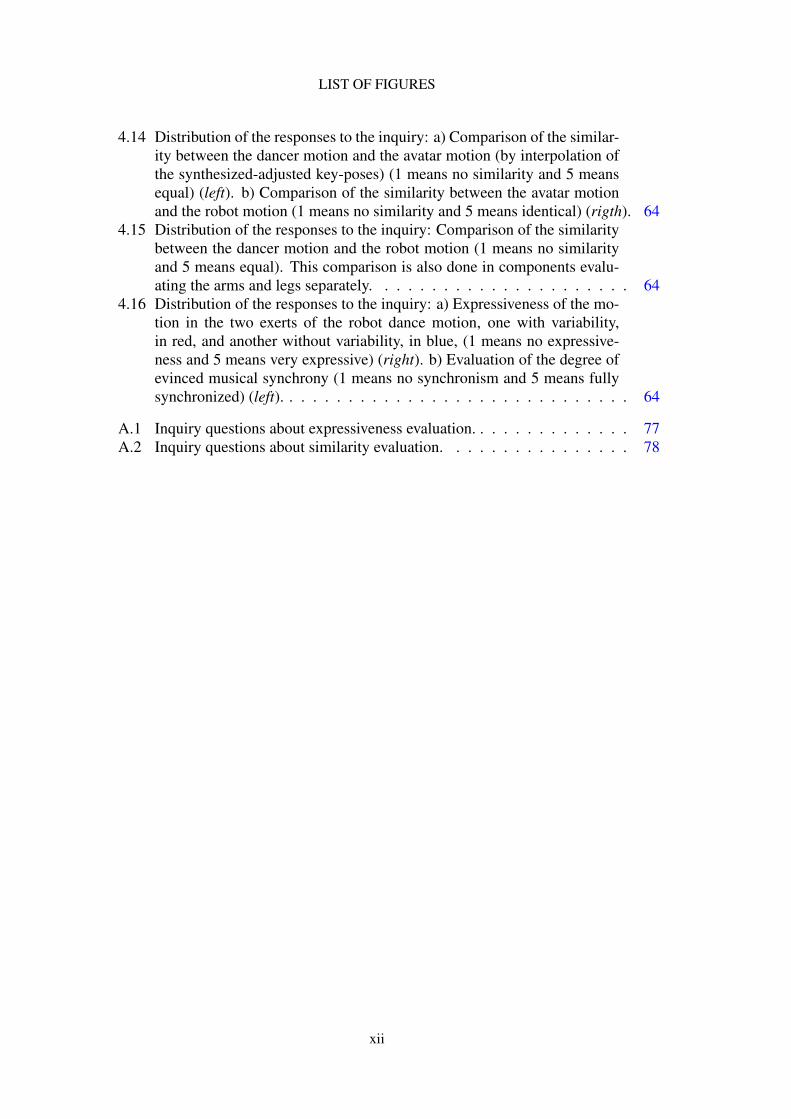
4.14 Distribution of the responses to the inquiry: a) Comparison of the similar-ity between the dancer motion and the avatar motion (by interpolation ofthe synthesized-adjusted key-poses) (1 means no similarity and 5 meansequal) (left). b) Comparison of the similarity between the avatar motionand the robot motion (1 means no similarity and 5 means identical) (rigth). 64
4.15 Distribution of the responses to the inquiry: Comparison of the similaritybetween the dancer motion and the robot motion (1 means no similarityand 5 means equal). This comparison is also done in components evalu-ating the arms and legs separately. . . . . . . . . . . . . . . . . . . . . . 64
4.16 Distribution of the responses to the inquiry: a) Expressiveness of the mo-tion in the two exerts of the robot dance motion, one with variability,in red, and another without variability, in blue, (1 means no expressive-ness and 5 means very expressive) (right). b) Evaluation of the degree ofevinced musical synchrony (1 means no synchronism and 5 means fullysynchronized) (left). . . . . . . . . . . . . . . . . . . . . . . . . . . . . . 64
A.1 Inquiry questions about expressiveness evaluation. . . . . . . . . . . . . . 77A.2 Inquiry questions about similarity evaluation. . . . . . . . . . . . . . . . 78
xii
List of Tables
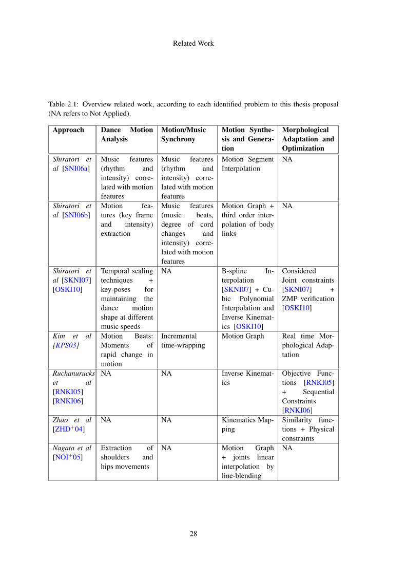
2.1 Overview related work, according to each identified problem to this thesisproposal (NA refers to Not Applied). . . . . . . . . . . . . . . . . . . . . 28
4.1 Comparison of the Correlation coefficients between the different key-posesynthesis methods, in relation to the spatiotemporal dimensionality (Dim)and level of reduction (Reduction) of their respective representation mod-els. [ONG+11] . . . . . . . . . . . . . . . . . . . . . . . . . . . . . . . 49
4.2 Comparison of the total body size expected with the obtained (values inmm). . . . . . . . . . . . . . . . . . . . . . . . . . . . . . . . . . . . . . 50
4.3 Comparison of the total body sizes for different scaling factors and NAO’smorphology. . . . . . . . . . . . . . . . . . . . . . . . . . . . . . . . . . 52
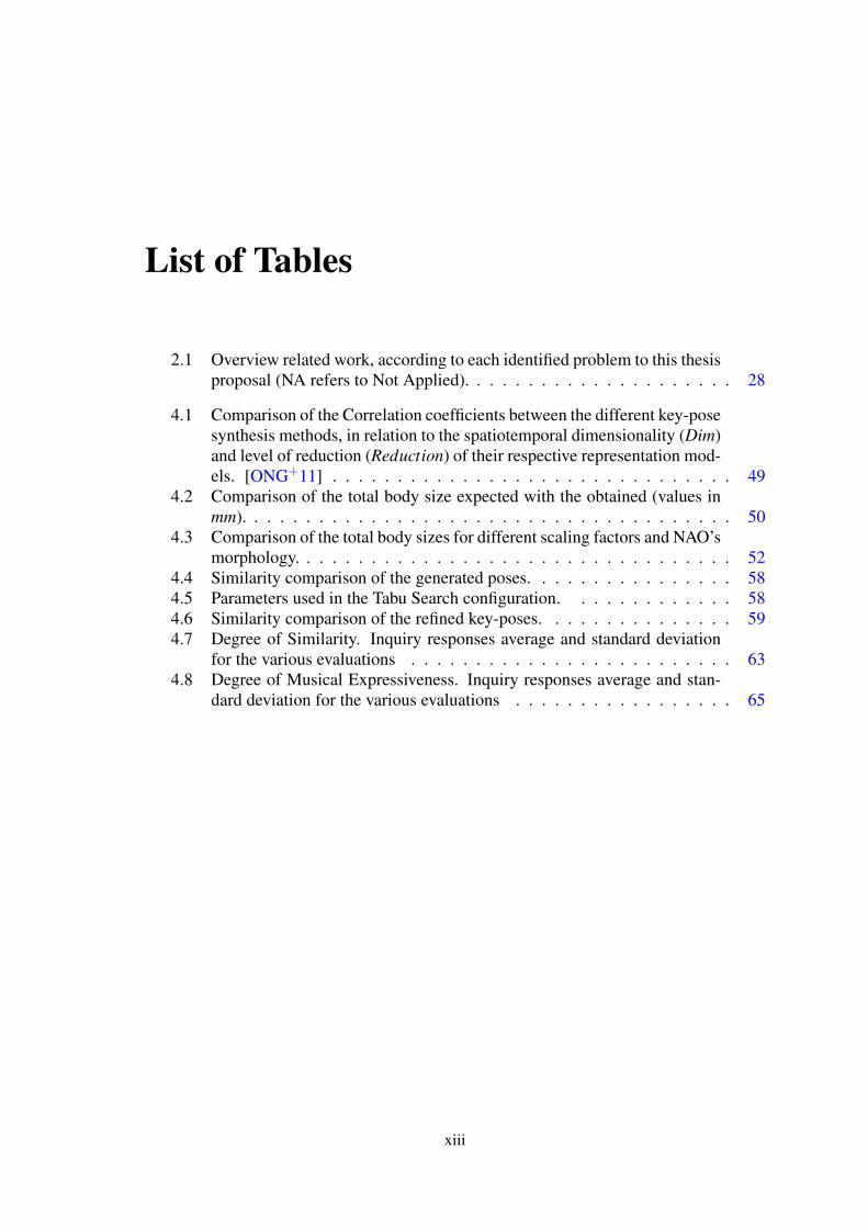
4.4 Similarity comparison of the generated poses. . . . . . . . . . . . . . . . 584.5 Parameters used in the Tabu Search configuration. . . . . . . . . . . . . 584.6 Similarity comparison of the refined key-poses. . . . . . . . . . . . . . . 594.7 Degree of Similarity. Inquiry responses average and standard deviation
for the various evaluations . . . . . . . . . . . . . . . . . . . . . . . . . 634.8 Degree of Musical Expressiveness. Inquiry responses average and stan-
dard deviation for the various evaluations . . . . . . . . . . . . . . . . . 65
xiii

LIST OF TABLES
xiv

Acronyms
DoF Degree of Freedom
FK Forward Kinematics
GA Genetic Algorithm
HC Hill ClimbingHMM Hidden Markov modelHRI Human-Robot Interaction
IK Inverse Kinematics
LDA Linear Discriminant Analysis
MoCap Motion Capture
PSO Particle Swarm OptimizationPFS Partial Fourier Series
SA Simulated Annealing
TCP Transmission Control ProtocolTGA Topological Gesture AnalysisTS Tabu Search
UDP User Datagram Protocol
ZMP Zero Moment Point
XML Extensible Markup Language
xv

ABBREVIATIONS
xvi
Chapter 1
Introduction
This thesis focus on mapping motion captured human movements onto humanoid robots.The goal is to generate Samba dance motion for a humanoid robot, for this motion sambamotion data is analyzed to build a spatiotemporal representation. From this representationkey-poses are generated, this poses will suffer morphological adaptation to ensure thehumanoid kinematic constraints. Refinement of this key-poses is done to increase thesimilarity and in the end the key-poses will be interpolated in order to build the robotdance motion.
1.1 Motivation
Robotics applications grow daily, and the creation of realistic motion for humanoid robotsincreasingly plays a key role, as important forms of interaction between humanoid robotsand humans already happen by means of non-verbal communication. This gives greaterimportance and interest on increasing the robot motion similarity to the different kinds ofhuman motion behaviors.
As dance motion forms a rich, complex and expressive class of human motions itpresents a good case study to help designing realistic forms of robotic motion. Dancemovements also have a strong emotional meaning and expressive symbolism, makingthem powerful forms of non-verbal communication that would allow to improve human-robot social interaction by means of bodily communication. In this sense, the usage ofhuman motion capture (MoCap) data provides a detailed description of the original move-ments trajectories, enabling an easier and more realistic replication of these motion byhumanoid robots.
The proposed method, in this case applied to dance movements, can allow an easierand more detailed construction of rich and diverse movements for humanoid robots, with
1
Introduction
different body morphologies. Such process can be easily extended to the learning ofdifferent humanoid movement patterns (repetitive motions), inherent to the performanceof several simple daily-life tasks, such as biped locomotion or even basic sports’ gaits,such as kicking or swimming. Not only would it give humanoid robots a greater amplitudeof movements and possible actions, but would also introduce a new and simpler way todesign, and in a certain way program, different kinds of robot movements and behaviors.
1.1.1 Applications
Further motivation for work in this area can be found in the several areas of the possibleapplications of such techniques:
• Entertainment: As we assist to the increasing role of robotics in entertainmentareas, enhancing robotic movements, such as dancing, would help achieving morerealistic and expressive behaviors, which would greatly enhance the amuse of thehuman-robot interaction (HRI).
• Education: The proposed approach can be used as the basis beyond choreographictools, for robots and humans, and as an edutainment platform for captivating stu-dents from different backgrounds and ages to interdisciplinary themes such as dance,music, rhythm, robotics, kinematics and dynamics.
• Research: Many of the problems addressed are of great interest in researching, withespecial focus on artificial (computational) musical cognition and motor embodi-ment, and generic issues beyond robotic motion kinematics and dynamics, appliedto different humanoid body models.
As stated, the presented method was applied, as case-study, to dance movements, butcould also be easily adapted to other different kinds of motion, increasing the numberand types of potential future applications. Besides, the proposed method was designedfor supporting different humanoid body models, which open application channels acrossdifferent humanoid robotic platforms.
1.2 Goals
The aim of this thesis is to map motion captured human periodic motion, dance motion inthis case, onto humanoid robots. In this thesis we will focus on the generation of dancemotion, replicating different dance styles, mainly Samba.
In order to archive this main goal there are some more specific goals for this thesis:
• Study relevant kinematic techniques for generating robotics motion;
2
Introduction
• Study and get familiarized with human motion capture systems and data;
• Analyze motion/musical relations in Traditional dance styles.
• Get familiarized with different choreographic methods for representing dance ac-cording to musical rhythm;
• Develop methods for adapting captured human motion data onto different humanoidmorphologies;
• Synthesize the original dance motion assuring musical synchrony;
• Test and simulate the generated motion using a generic robotics simulator;
• Quantitatively and qualitatively evaluate the generated humanoid robot dance interms of similarity with the original dance and degree of musical expressiveness.
The final result of this thesis should consist on several methods that allow the repro-duction, by humanoid robots, of captured dance motion patterns, with especial on thekinematics of the motion.
1.3 Methodology and Tools
To achieve the proposed goals, firstly there should be a study of the different motion cap-ture systems to understand the way as human motion is recorded. Afterwards we shouldanalyze different motion data, previously captured from human dancing performances forextracting fundamental dance patterns in the original dance motion, and treat it in orderto create a middle-term representation of the key-poses that will be mapped into the usedhumanoid robot. Knowing what poses the robot must perform, we need to adapt thosemovements from the human morphology to the robot morphology, having in mind themorphological differences between both bodies and the kinematic constraints imposedby the used humanoid body model. This transformation/transference should be testedin a proper robotics simulation environment towards keeping the overall aspect of thekey-poses, and the relative relation of all the robot body parts. Ultimately, an overalloptimization of the synthesized key-poses should take place in order to achieve greatersimilarity with the original motion.
In the following subsections, some topics, tools, and techniques that have interest tothis thesis are presented, serving as base knowledge to the following work.
3
Introduction
1.3.1 Motion Capture and Analysis
1.3.1.1 Motion Capture System
Motion capture is the term applied to the process of recording real motion and convertingthat motion onto a digital model. There are many kinds of motion capture systems, suchas mechanical, magnetic and optical.
In a mechanical system, the performer wears a mechanical device, or exoskeleton,which was angle measuring equipments installed at the joints locations. As the performermoves, the sensors also move, measuring the joint angles of the performer, and so obtain-ing the orientation of the performer body parts. These systems are accurate and cheap,however it is not easy to perform fast and expressive motion due to the weight of theexoskeleton and the limited rand of the angle measurement devices [dA03].
Magnetic systems utilize sensors placed on the body and a known magnetic field isset up. The sensors and source are connected by a cable to an electronic control unitthat calculates the locations and orientation of the limbs based on the generated mag-netic field [Dic] . This technique enables real-time data collection and overcomes oc-clusion [dA03]. Yet, this type of systems has many limitations: it requires a physicalconnection (wires) with the sensors; it has a limited range; and sensors from differentactors will interfere with each other. Making it harder to perform some movements.
The last type of motion capture systems are the optical ones. In these systems theperformer wears a suit with special markers attached to it. The markers are retro-reflexive,and are placed in a way that the position of every body part can be easily acquired byseveral cameras surrounding the space where the performer moves. Each marker must becaptured by at least 2 cameras, and a greater number of cameras diminishes the possibilityof occlusions [Sch10]. Yet, for full body capture there must be 8 to 16 cameras (ormore) [Dic]. The cameras will capture the reflex of the markers and the several imagesof a marker, from the various cameras, are matched using triangulation to compute themarkers positions in 3D space [Dic]. The main advantages of optical systems are thevery high rates of data collection and the possibility to create a great range of motionin a relatively large space [dA03]. Such systems can then capture larger areas, andare especially useful for capturing complex types of motion, such as sport actions ordancing [Dic].
Given the scope of this work upon dance movements, we used MoCap data of sambadance, performed by professional dancers, which was captured by an optical motion cap-ture system. The used MoCap system was an Optitrack from Natural Point [Nat], recur-ring to 8 cameras positioned around the dancer.
4
Introduction
1.3.1.2 MATLAB MoCap Toolbox
The MoCap Toolbox [TB10] is a Matlab toolbox that contains functions for the analysisand visualization of motion capture data. The toolbox is mainly aimed for the analysis ofmusic-related movement, but might be useful in other areas of study as well [TB10].
It will be used for analyzing the kinematics of the original human body motion trajec-tories and studying its musical relationship, obtaining this way a middle-term representa-tion of the original dance style.
1.3.2 Musical Rhythmic Qualities
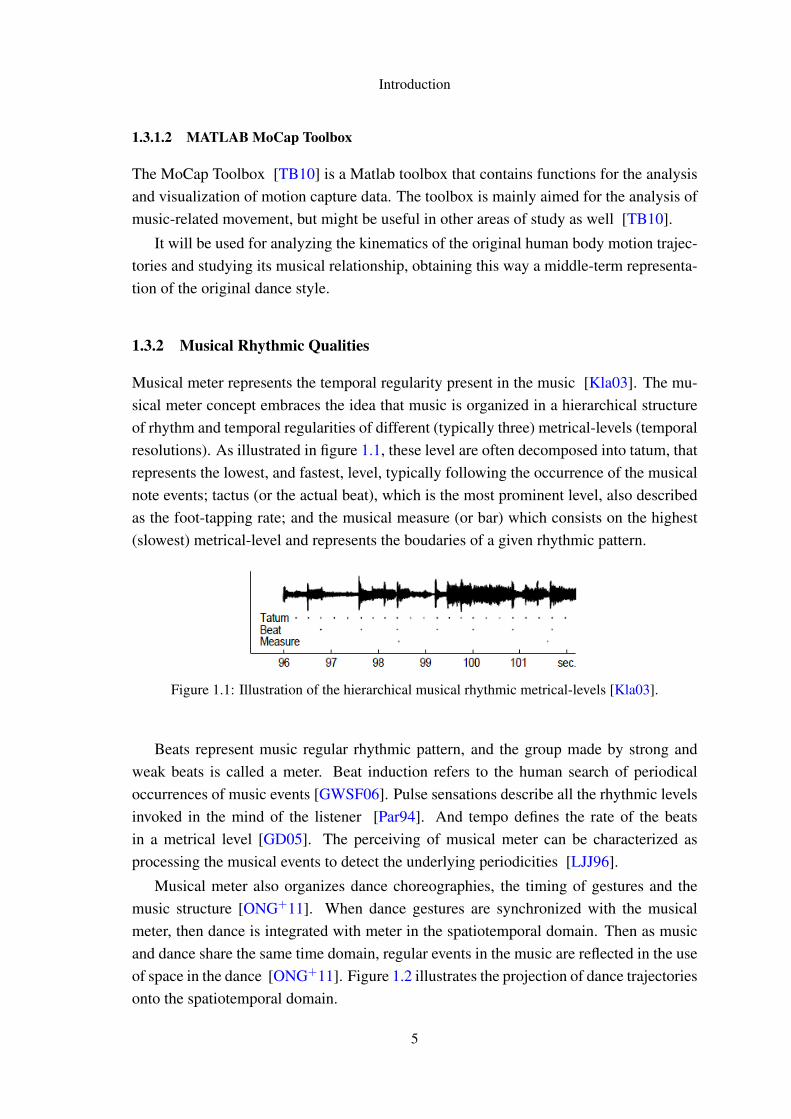
Musical meter represents the temporal regularity present in the music [Kla03]. The mu-sical meter concept embraces the idea that music is organized in a hierarchical structureof rhythm and temporal regularities of different (typically three) metrical-levels (temporalresolutions). As illustrated in figure 1.1, these level are often decomposed into tatum, thatrepresents the lowest, and fastest, level, typically following the occurrence of the musicalnote events; tactus (or the actual beat), which is the most prominent level, also describedas the foot-tapping rate; and the musical measure (or bar) which consists on the highest(slowest) metrical-level and represents the boudaries of a given rhythmic pattern.
Figure 1.1: Illustration of the hierarchical musical rhythmic metrical-levels [Kla03].
Beats represent music regular rhythmic pattern, and the group made by strong andweak beats is called a meter. Beat induction refers to the human search of periodicaloccurrences of music events [GWSF06]. Pulse sensations describe all the rhythmic levelsinvoked in the mind of the listener [Par94]. And tempo defines the rate of the beatsin a metrical level [GD05]. The perceiving of musical meter can be characterized asprocessing the musical events to detect the underlying periodicities [LJJ96].
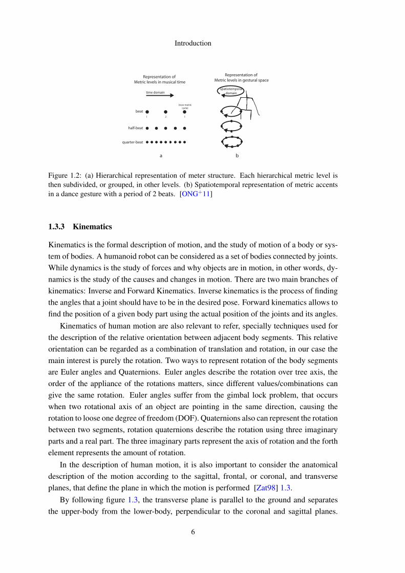
Musical meter also organizes dance choreographies, the timing of gestures and themusic structure [ONG+11]. When dance gestures are synchronized with the musicalmeter, then dance is integrated with meter in the spatiotemporal domain. Then as musicand dance share the same time domain, regular events in the music are reflected in the useof space in the dance [ONG+11]. Figure 1.2 illustrates the projection of dance trajectoriesonto the spatiotemporal domain.
5
Introduction
Representation of Metric levels in musical time
Representation of Metric levels in gestural space
beat
half-beat
quarter-beat
time domain
(new metriccycle)
spatiotemporaldomain
a b
1 2 1
Figure 1.2: (a) Hierarchical representation of meter structure. Each hierarchical metric level isthen subdivided, or grouped, in other levels. (b) Spatiotemporal representation of metric accentsin a dance gesture with a period of 2 beats. [ONG+11]
1.3.3 Kinematics
Kinematics is the formal description of motion, and the study of motion of a body or sys-tem of bodies. A humanoid robot can be considered as a set of bodies connected by joints.While dynamics is the study of forces and why objects are in motion, in other words, dy-namics is the study of the causes and changes in motion. There are two main branches ofkinematics: Inverse and Forward Kinematics. Inverse kinematics is the process of findingthe angles that a joint should have to be in the desired pose. Forward kinematics allows tofind the position of a given body part using the actual position of the joints and its angles.
Kinematics of human motion are also relevant to refer, specially techniques used forthe description of the relative orientation between adjacent body segments. This relativeorientation can be regarded as a combination of translation and rotation, in our case themain interest is purely the rotation. Two ways to represent rotation of the body segmentsare Euler angles and Quaternions. Euler angles describe the rotation over tree axis, theorder of the appliance of the rotations matters, since different values/combinations cangive the same rotation. Euler angles suffer from the gimbal lock problem, that occurswhen two rotational axis of an object are pointing in the same direction, causing therotation to loose one degree of freedom (DOF). Quaternions also can represent the rotationbetween two segments, rotation quaternions describe the rotation using three imaginaryparts and a real part. The three imaginary parts represent the axis of rotation and the forthelement represents the amount of rotation.
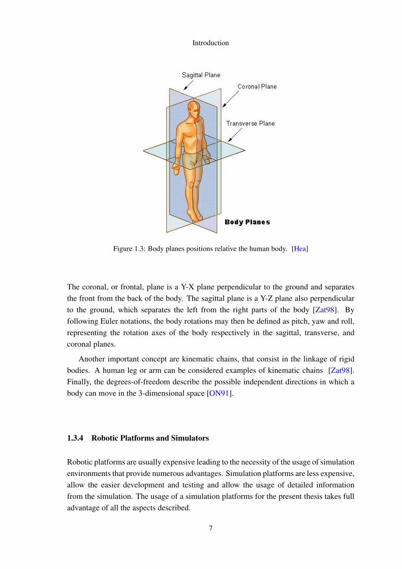
In the description of human motion, it is also important to consider the anatomicaldescription of the motion according to the sagittal, frontal, or coronal, and transverseplanes, that define the plane in which the motion is performed [Zat98] 1.3.
By following figure 1.3, the transverse plane is parallel to the ground and separatesthe upper-body from the lower-body, perpendicular to the coronal and sagittal planes.
6
Introduction
Figure 1.3: Body planes positions relative the human body. [Hea]
The coronal, or frontal, plane is a Y-X plane perpendicular to the ground and separatesthe front from the back of the body. The sagittal plane is a Y-Z plane also perpendicularto the ground, which separates the left from the right parts of the body [Zat98]. Byfollowing Euler notations, the body rotations may then be defined as pitch, yaw and roll,representing the rotation axes of the body respectively in the sagittal, transverse, andcoronal planes.
Another important concept are kinematic chains, that consist in the linkage of rigidbodies. A human leg or arm can be considered examples of kinematic chains [Zat98].Finally, the degrees-of-freedom describe the possible independent directions in which abody can move in the 3-dimensional space [ON91].
1.3.4 Robotic Platforms and Simulators
Robotic platforms are usually expensive leading to the necessity of the usage of simulationenvironments that provide numerous advantages. Simulation platforms are less expensive,allow the easier development and testing and allow the usage of detailed informationfrom the simulation. The usage of a simulation platforms for the present thesis takes fulladvantage of all the aspects described.
7
Introduction
1.3.4.1 SimSpark
SimSpark is a generical simulator, that supports developing physical simulations androbotics research. Different agents can participate in one simulation, connecting to SimSparkusing UDP or TCP. SimSpark uses the Open Dynamics Engine (ODE) for simulating rigidbody dynamics. It is commonly used in academic research and education. [OR04]
It will allow simulating and debugging the motion developed for robot NAO. It willserve as platform for the experimentation on a simulated humanoid NAO.
1.3.4.2 NAO
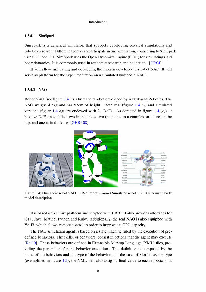
Robot NAO (see figure 1.4) is a humanoid robot developed by Alderbaran Robotics. TheNAO weighs 4.5kg and has 57cm of height. Both real (figure 1.4 a)) and simulatedversions (figure 1.4 b)) are endowed with 21 DoFs. As depicted in figure 1.4 (c)), ithas five DoFs in each leg, two in the ankle, two (plus one, in a complex structure) in thehip, and one at in the knee [GHB+08].
Figure 1.4: Humanoid robot NAO. a) Real robot. middle) Simulated robot. right) Kinematic bodymodel description.
It is based on a Linux platform and scripted with URBI. It also provides interfaces forC++, Java, Matlab, Python and Ruby. Additionally, the real NAO is also equipped withWi-Fi, which allows remote control in order to improve its CPU capacity.
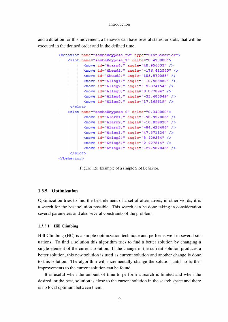
The NAO simulation agent is based on a state machine ruled by the execution of pre-defined behaviors. The skills, or behaviors, consist in actions that the agent may execute[Rei10]. These behaviors are defined in Extensible Markup Language (XML) files, pro-viding the parameters for the behavior execution. This definition is composed by thename of the behaviors and the type of the behaviors. In the case of Slot behaviors type(exemplified in figure 1.5), the XML will also assign a final value to each robotic joint
8
Introduction
and a duration for this movement, a behavior can have several states, or slots, that will beexecuted in the defined order and in the defined time.
Figure 1.5: Example of a simple Slot Behavior.
1.3.5 Optimization
Optimization tries to find the best element of a set of alternatives, in other words, it isa search for the best solution possible. This search can be done taking in considerationseveral parameters and also several constraints of the problem.
1.3.5.1 Hill Climbing
Hill Climbing (HC) is a simple optimization technique and performs well in several sit-uations. To find a solution this algorithm tries to find a better solution by changing asingle element of the current solution. If the change in the current solution produces abetter solution, this new solution is used as current solution and another change is doneto this solution. The algorithm will incrementally change the solution until no furtherimprovements to the current solution can be found.
It is useful when the amount of time to perform a search is limited and when thedesired, or the best, solution is close to the current solution in the search space and thereis no local optimum between them.
9
Introduction
1.3.5.2 Simulated Annealing
Simulated Annealing (SA) [KGV83] is inspired in a metallurgy technique involving heat-ing and controlled cooling of a material. This slow and controlled cooling process isknown as annealing.
By analogy with this metallurgic process, the SA algorithm takes the current solutionto a problem and replaces it with a new random one that is close to the current solution.This random choosing of a new solution is done using a probability that depends on thedifference between the solutions and on a global parameter, the temperature that decreasesduring the search process. With larger temperatures the solution changes more randomly.This allows that in the beginning the method avoids becoming stuck at local optima. Incontrast to HC, that only updates the solution when finds a better one, in SA the newsolution can be worse than the current solution.
1.3.5.3 Tabu Search
Tabu Search (TS) [Glo86], was proposed in 1986 by Fred Golver. In TS, a list of all thevisited solutions is kept, called to tabu list. This avoids visiting twice the same solution.
In the algorithm, each visited node is declared as a tabu and is placed in the tabu list.And then the algorithm searches the neighboring nodes that still aren’t in the tabu list. TSwill test all the possible solutions and in the end chose the best one.
1.3.5.4 Particle Swarm
Particle Swarm Optimization (PSO) [Ebe06] is based on an evolutionary algorithm. PSOtries to optimize a solution by iteratively trying to improve a candidate solution, with re-gard to the solution evaluation. Starting with a set of randomly generated solutions, PSOthen searches for a optima solution by upgrading the solutions. Each particle has twocharacteristics: position and velocity. The potential solutions, or particles, will wanderaround the problem space, and always remembers the best position visited, and the so-lution value to that position. The particles can communicate with which other and adapttheir velocity or position to the information received. During the several iterations of thealgorithm the particles may converge to the optimum or diverge from it.
1.3.5.5 Genetic Algorithm
Genetic Algorithm (GA) [Hol75] is an optimization method inspired, in a certain way, inthe natural reproduction system and in the evolution of biological systems. In a GA, theinitial population, that may be called chromosomes), is optimized toward a better solution.Each solution, or chromosome, is nothing else but a set of genes.
10
Introduction
The initial solution can be calculated randomly or by a creation function, it only needsto be an acceptable solution to the problem. Using this initial population, the algorithmstarts and creates new populations using selection, crossover and mutation operations.Selection will specify the parents to the next generation. Crossover will generate a newchild from the two parents; the child will inherit genes from the parents. Mutation pro-duces mutation of children, in order to include random variations on the children’s genes.
1.4 Research Institutions
This thesis wad done at LIACC, under the supervising of Ph.D Luis Paulo Reis, and atINESC Porto, under the supervising of Ph.D Fabien Gouyon. It also counted with theco-supervision of João Lobato Oliveira, from both institutions
LIACC (Laboratory of Artificial Intelligence and Computer Science of the Univer-sity of Porto) was created in 1988 in order to promote the collaboration of researchersthat were separately working in the fields of Computer Science and Artificial Intelligencein different Faculties. It aims to help solving general computer science problems, fromsecurity to software reliability. LIACC works in different research areas: Advanced Pro-gramming Systems, Distributed Artificial Intelligence and Robotics, Formal Models ofComputation, and Language, Complexity and Cryptography.
INESC (Institute for Systems and Computer Engineering) of Porto, is an interface in-stitution between the academic world and the world of industry and services, as well asthe public administration. The area of activity ranges from research and development,to technology transfer, consulting and advanced training. The main research areas areTelecommunications and Multimedia, Power Systems, Manufacturing Systems Engineer-ing, Information and Communication Systems, and Optoelectronics.
1.5 Thesis Outline
The remainder of this thesis is divided in four chapters. Section II describes some relatedwork to this thesis, and several approaches in the area. Section III presents the proposedmethodology and describes the developed work. In Section IV the obtained results arediscussed. Finally in Section V the conclusions are depicted and some paths for the futurework are presented.
11

Introduction
12
Chapter 2
Related Work
This chapter describes the state-of-the-art in this area, and also presents some relatedworks and their methodology expressing the results and problems that they faced. Thiswill help to identify the main difficulties that can appear in the project and also some ofthe problems that this project can resolve.
One of the main topics of interest for this work is the analysis of motion data, concern-ing the methods used to analyze and mine the motion capture data. In other words, theway that the information is treated, the tools or methods used and also some specificationsof each approach.
Another interesting topic in this area is how that motion can be then synthesized andreplicated by different humanoid models. Here is useful to study robotic approaches,and methods used in computer animated systems, for laboring the extracted motion datauntil replicating it by the chosen humanoid model. Given this problem’s relevance inthe literature, it is important to also look at the results obtained and the problems facedby the recent approaches from the literature. In relation to robotic motion generation,it is also useful to study some applications of optimization or refinement of movement.Specifically to this case, it is of greater interest to look at works that use the same roboticplatform intended for this project, robot NAO.
In the end, a small review of all the work is made, presenting some of the problemsand challenges found and faced by similar works. This is important in order to proposesome novel approaches to some of the related problems.
2.1 Dance Motion Analysis
As already stated, the first goal is to use motion analysis in order to search and work withcaptured human dance motion data, and this way this way build a middle-term represen-
13
Related Work
tation of the dance motion. Several methods have been used for analysis of dance motioncaptured data: some only analyze motion data of specific parts of the human body whileothers analyze all the body; and some only consider the body motion while others alsotake into account its musical relation.
Firstly, some methods regarding only motion analysis are presented and after it meth-ods that use music and motion analysis to keep their intrinsic synchronism.
Nagata et al. takes basic knowledge from the main characteristics of a Latin dance[NOI+05]. Using that, they determine what information of the motion data will be ex-tracted to represent the dance. Information related to the movement of shoulders and hipswere extracted and analyzed. In particular, the rotation related to a plane vertical to thefloor and related to a plane horizontal and parallel to the floor were calculated.
Nakaoka et al., [NNIY02] and [NNY+03], segmented the dance, in key-poses, interms of minimum velocity of the end-effectors’ (hands and feet). Then these key-poseswere clustered and interpolated to generate the original dance.
Different approaches that try to analyze, study and generate dance motion well matchedto music are also important and of even greater interest, since there is a close relationshipbetween musical rhythm and motion rhythm.
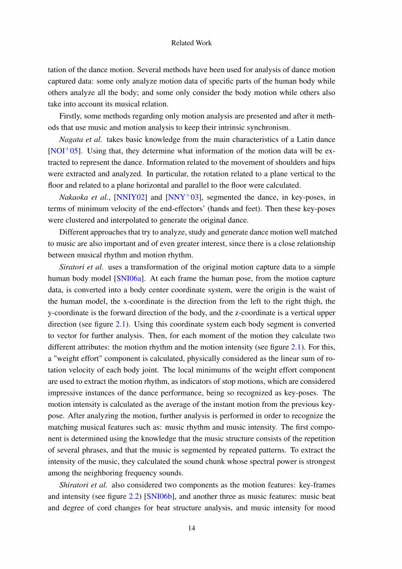
Siratori et al. uses a transformation of the original motion capture data to a simplehuman body model [SNI06a]. At each frame the human pose, from the motion capturedata, is converted into a body center coordinate system, were the origin is the waist ofthe human model, the x-coordinate is the direction from the left to the right thigh, they-coordinate is the forward direction of the body, and the z-coordinate is a vertical upperdirection (see figure 2.1). Using this coordinate system each body segment is convertedto vector for further analysis. Then, for each moment of the motion they calculate twodifferent attributes: the motion rhythm and the motion intensity (see figure 2.1). For this,a "weight effort" component is calculated, physically considered as the linear sum of ro-tation velocity of each body joint. The local minimums of the weight effort componentare used to extract the motion rhythm, as indicators of stop motions, which are consideredimpressive instances of the dance performance, being so recognized as key-poses. Themotion intensity is calculated as the average of the instant motion from the previous key-pose. After analyzing the motion, further analysis is performed in order to recognize thematching musical features such as: music rhythm and music intensity. The first compo-nent is determined using the knowledge that the music structure consists of the repetitionof several phrases, and that the music is segmented by repeated patterns. To extract theintensity of the music, they calculated the sound chunk whose spectral power is strongestamong the neighboring frequency sounds.
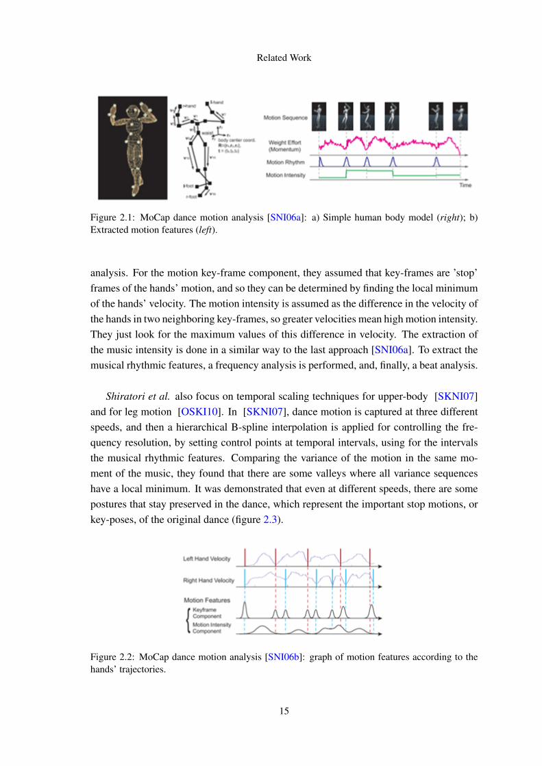
Shiratori et al. also considered two components as the motion features: key-framesand intensity (see figure 2.2) [SNI06b], and another three as music features: music beatand degree of cord changes for beat structure analysis, and music intensity for mood
14
Related Work
Figure 2.1: MoCap dance motion analysis [SNI06a]: a) Simple human body model (right); b)Extracted motion features (left).
analysis. For the motion key-frame component, they assumed that key-frames are ’stop’frames of the hands’ motion, and so they can be determined by finding the local minimumof the hands’ velocity. The motion intensity is assumed as the difference in the velocity ofthe hands in two neighboring key-frames, so greater velocities mean high motion intensity.They just look for the maximum values of this difference in velocity. The extraction ofthe music intensity is done in a similar way to the last approach [SNI06a]. To extract themusical rhythmic features, a frequency analysis is performed, and, finally, a beat analysis.
Shiratori et al. also focus on temporal scaling techniques for upper-body [SKNI07]and for leg motion [OSKI10]. In [SKNI07], dance motion is captured at three differentspeeds, and then a hierarchical B-spline interpolation is applied for controlling the fre-quency resolution, by setting control points at temporal intervals, using for the intervalsthe musical rhythmic features. Comparing the variance of the motion in the same mo-ment of the music, they found that there are some valleys where all variance sequenceshave a local minimum. It was demonstrated that even at different speeds, there are somepostures that stay preserved in the dance, which represent the important stop motions, orkey-poses, of the original dance (figure 2.3).
Figure 2.2: MoCap dance motion analysis [SNI06b]: graph of motion features according to thehands’ trajectories.
15
Related Work
Figure 2.3: a) Joint angles variance performed at different musical speeds (top row); b) Extractedkey-poses (middle row); c) Important stop-motions, drawn by professional choreographers (bottomrow) [SKNI07].
In [OSKI10], Shiratori et al. proposes a similar method to [SKNI07], but now adaptedto the leg motion. The concept of key-pose is also used, but now the analysis focus onstep motions. From the observation of the motion in the different velocities, they foundthat the time and stride of the step, near a key-pose, tends to be maintained, that a kickingaction with the increase of velocity tends to look like a normal step, and that the speedof a swing foot won’t accelerate in the same proportion as the increase of velocity ofthe music. All this indicates that the dancers made more effort to maintain the originaltimings for tasks around key-poses and that the dancers tried to maintain stride length asclose to the original one as possible around key-pose timings.
Ofli et al. used 3 Hidden Markov model (HMM’s) to capture the dynamic behaviorof the dancing body trajectories [OCFT+08]. One models the motion of the torso, otherthe movement of the arms and a third for the movement of the legs. For the music anal-ysis, the tempo and the relevant beat information is used to drive the movement. Tempois estimated in terms of beat per minute, and the beat location is computed from peri-odicity estimation. For motion analysis, the start and end frames of each dance figureare manually labeled, and then the three HMM models of each dance figure are trainedin a supervised manner with the body posture parameters captured from those manuallylabeled segments.
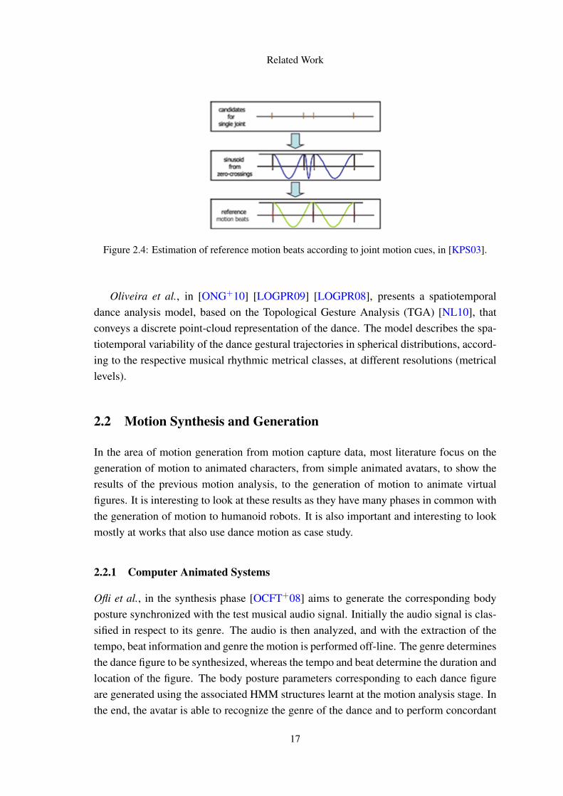
Kim et al. extracts rapid directional changes in a motion [KPS03]. These moments aredetected from the zero-crossing of the second derivative of each motion signal at everyframe. So they extract the zero-crossing moments of the joint orientation signals, andclassify these moments as candidates for motion beats. The sequence of candidates ex-tracted from a motion signal embeds a periodic pattern. From this sequence are calculatedsome reference beats, and then estimated the actual motion beats from the candidates us-ing these reference beats as guide (figure 2.4).
16
Related Work
Figure 2.4: Estimation of reference motion beats according to joint motion cues, in [KPS03].
Oliveira et al., in [ONG+10] [LOGPR09] [LOGPR08], presents a spatiotemporaldance analysis model, based on the Topological Gesture Analysis (TGA) [NL10], thatconveys a discrete point-cloud representation of the dance. The model describes the spa-tiotemporal variability of the dance gestural trajectories in spherical distributions, accord-ing to the respective musical rhythmic metrical classes, at different resolutions (metricallevels).
2.2 Motion Synthesis and Generation
In the area of motion generation from motion capture data, most literature focus on thegeneration of motion to animated characters, from simple animated avatars, to show theresults of the previous motion analysis, to the generation of motion to animate virtualfigures. It is interesting to look at these results as they have many phases in common withthe generation of motion to humanoid robots. It is also important and interesting to lookmostly at works that also use dance motion as case study.
2.2.1 Computer Animated Systems
Ofli et al., in the synthesis phase [OCFT+08] aims to generate the corresponding bodyposture synchronized with the test musical audio signal. Initially the audio signal is clas-sified in respect to its genre. The audio is then analyzed, and with the extraction of thetempo, beat information and genre the motion is performed off-line. The genre determinesthe dance figure to be synthesized, whereas the tempo and beat determine the duration andlocation of the figure. The body posture parameters corresponding to each dance figureare generated using the associated HMM structures learnt at the motion analysis stage. Inthe end, the avatar is able to recognize the genre of the dance and to perform concordant
17
Related Work
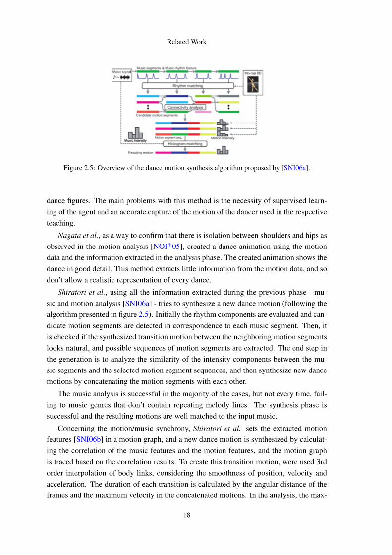
Figure 2.5: Overview of the dance motion synthesis algorithm proposed by [SNI06a].
dance figures. The main problems with this method is the necessity of supervised learn-ing of the agent and an accurate capture of the motion of the dancer used in the respectiveteaching.
Nagata et al., as a way to confirm that there is isolation between shoulders and hips asobserved in the motion analysis [NOI+05], created a dance animation using the motiondata and the information extracted in the analysis phase. The created animation shows thedance in good detail. This method extracts little information from the motion data, and sodon’t allow a realistic representation of every dance.
Shiratori et al., using all the information extracted during the previous phase - mu-sic and motion analysis [SNI06a] - tries to synthesize a new dance motion (following thealgorithm presented in figure 2.5). Initially the rhythm components are evaluated and can-didate motion segments are detected in correspondence to each music segment. Then, itis checked if the synthesized transition motion between the neighboring motion segmentslooks natural, and possible sequences of motion segments are extracted. The end step inthe generation is to analyze the similarity of the intensity components between the mu-sic segments and the selected motion segment sequences, and then synthesize new dancemotions by concatenating the motion segments with each other.
The music analysis is successful in the majority of the cases, but not every time, fail-ing to music genres that don’t contain repeating melody lines. The synthesis phase issuccessful and the resulting motions are well matched to the input music.
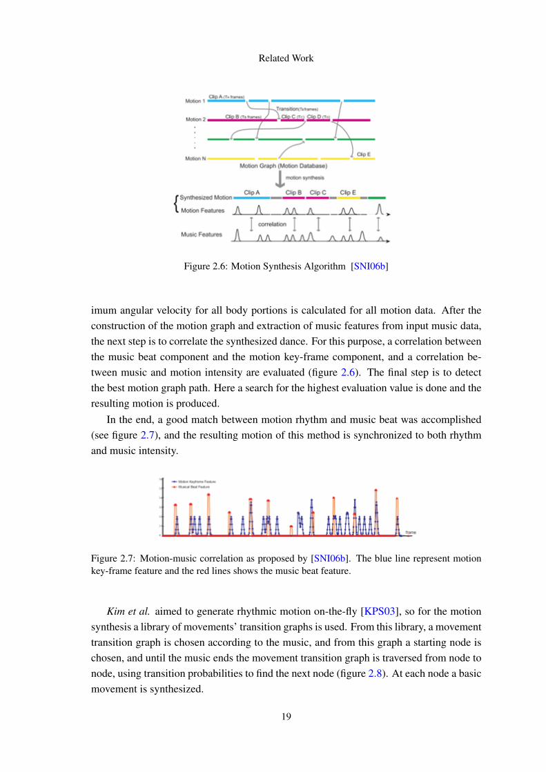
Concerning the motion/music synchrony, Shiratori et al. sets the extracted motionfeatures [SNI06b] in a motion graph, and a new dance motion is synthesized by calculat-ing the correlation of the music features and the motion features, and the motion graphis traced based on the correlation results. To create this transition motion, were used 3rdorder interpolation of body links, considering the smoothness of position, velocity andacceleration. The duration of each transition is calculated by the angular distance of theframes and the maximum velocity in the concatenated motions. In the analysis, the max-
18
Related Work
Figure 2.6: Motion Synthesis Algorithm [SNI06b]
imum angular velocity for all body portions is calculated for all motion data. After theconstruction of the motion graph and extraction of music features from input music data,the next step is to correlate the synthesized dance. For this purpose, a correlation betweenthe music beat component and the motion key-frame component, and a correlation be-tween music and motion intensity are evaluated (figure 2.6). The final step is to detectthe best motion graph path. Here a search for the highest evaluation value is done and theresulting motion is produced.
In the end, a good match between motion rhythm and music beat was accomplished(see figure 2.7), and the resulting motion of this method is synchronized to both rhythmand music intensity.
Figure 2.7: Motion-music correlation as proposed by [SNI06b]. The blue line represent motionkey-frame feature and the red lines shows the music beat feature.
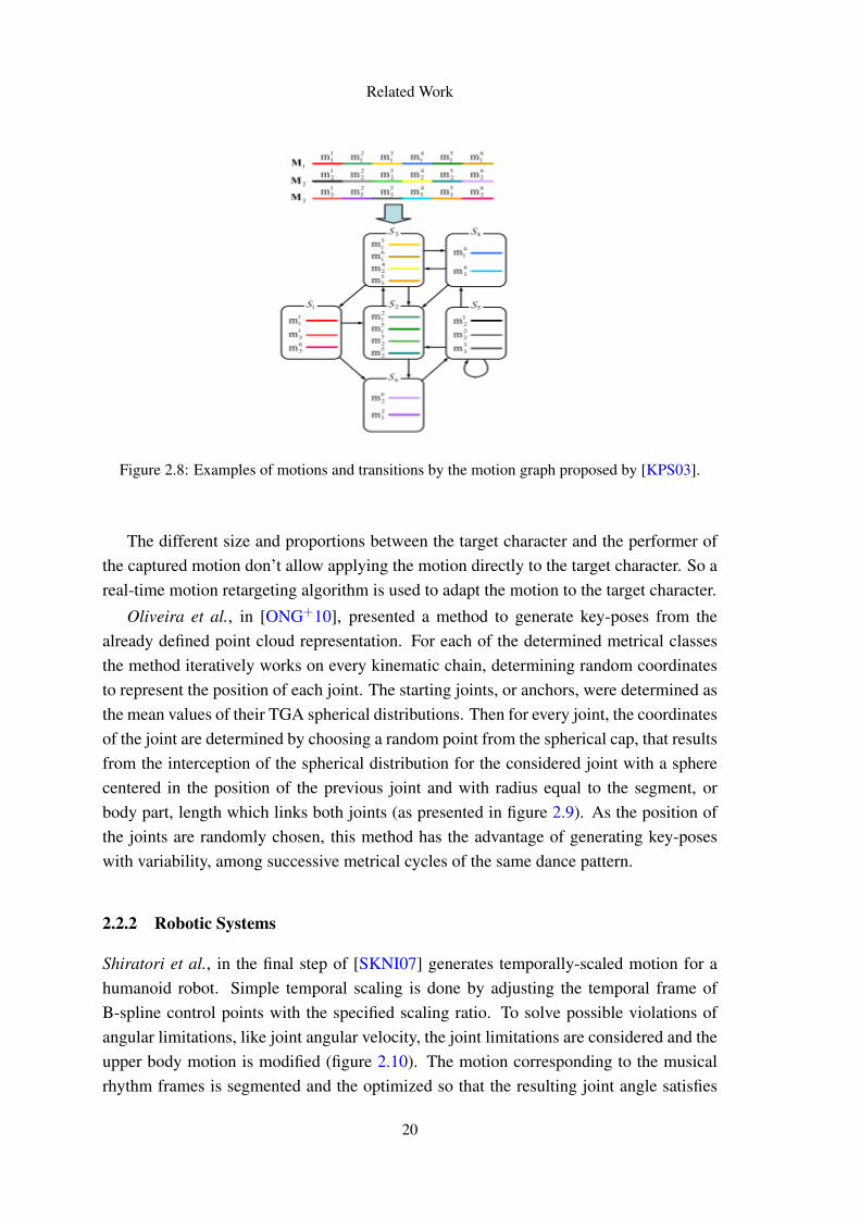
Kim et al. aimed to generate rhythmic motion on-the-fly [KPS03], so for the motionsynthesis a library of movements’ transition graphs is used. From this library, a movementtransition graph is chosen according to the music, and from this graph a starting node ischosen, and until the music ends the movement transition graph is traversed from node tonode, using transition probabilities to find the next node (figure 2.8). At each node a basicmovement is synthesized.
19
Related Work
Figure 2.8: Examples of motions and transitions by the motion graph proposed by [KPS03].
The different size and proportions between the target character and the performer ofthe captured motion don’t allow applying the motion directly to the target character. So areal-time motion retargeting algorithm is used to adapt the motion to the target character.
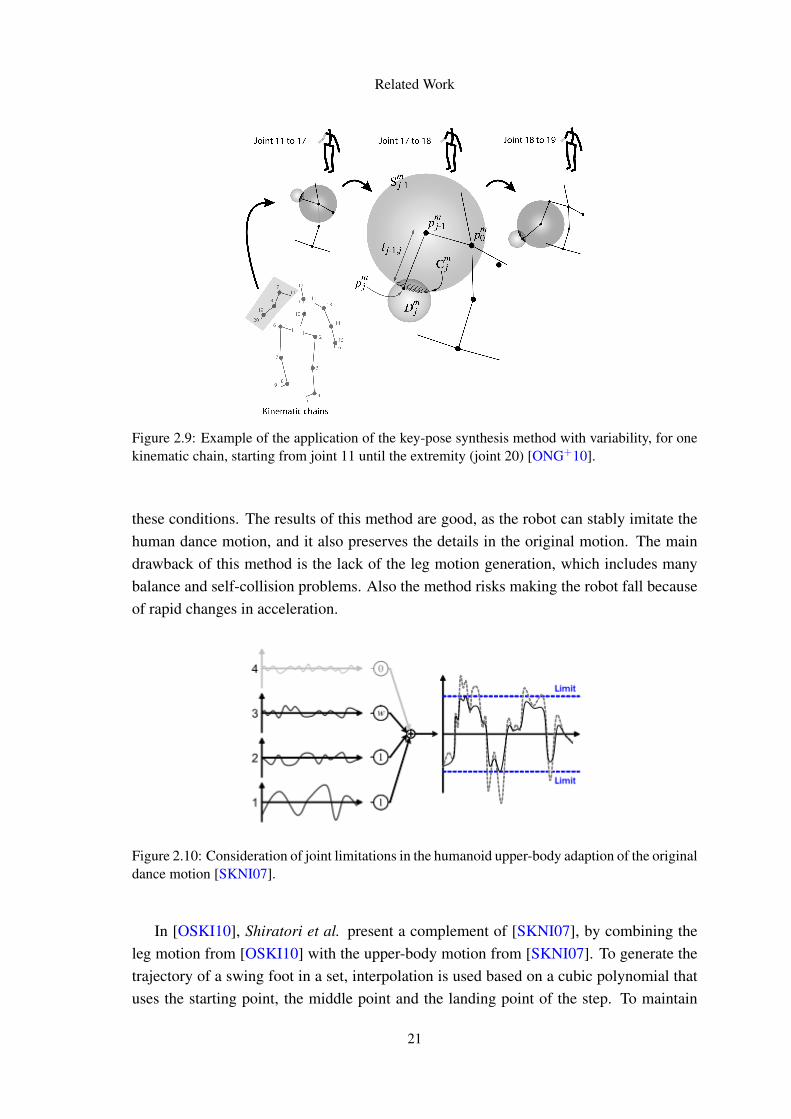
Oliveira et al., in [ONG+10], presented a method to generate key-poses from thealready defined point cloud representation. For each of the determined metrical classesthe method iteratively works on every kinematic chain, determining random coordinatesto represent the position of each joint. The starting joints, or anchors, were determined asthe mean values of their TGA spherical distributions. Then for every joint, the coordinatesof the joint are determined by choosing a random point from the spherical cap, that resultsfrom the interception of the spherical distribution for the considered joint with a spherecentered in the position of the previous joint and with radius equal to the segment, orbody part, length which links both joints (as presented in figure 2.9). As the position ofthe joints are randomly chosen, this method has the advantage of generating key-poseswith variability, among successive metrical cycles of the same dance pattern.
2.2.2 Robotic Systems
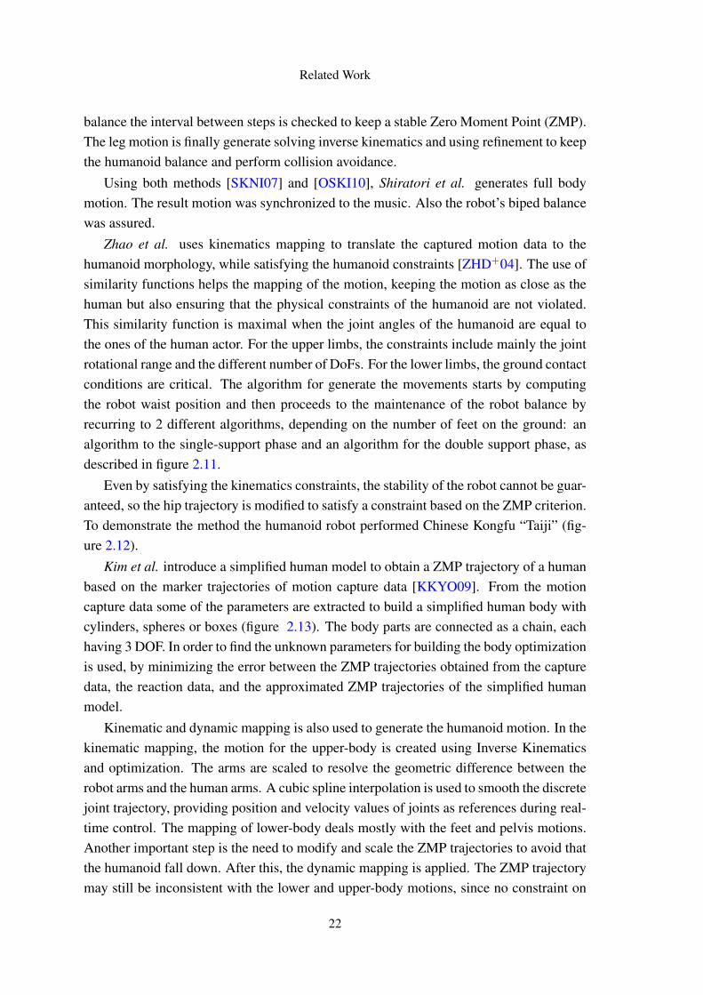
Shiratori et al., in the final step of [SKNI07] generates temporally-scaled motion for ahumanoid robot. Simple temporal scaling is done by adjusting the temporal frame ofB-spline control points with the specified scaling ratio. To solve possible violations ofangular limitations, like joint angular velocity, the joint limitations are considered and theupper body motion is modified (figure 2.10). The motion corresponding to the musicalrhythm frames is segmented and the optimized so that the resulting joint angle satisfies
20
Related Work
Figure 2.9: Example of the application of the key-pose synthesis method with variability, for onekinematic chain, starting from joint 11 until the extremity (joint 20) [ONG+10].
these conditions. The results of this method are good, as the robot can stably imitate thehuman dance motion, and it also preserves the details in the original motion. The maindrawback of this method is the lack of the leg motion generation, which includes manybalance and self-collision problems. Also the method risks making the robot fall becauseof rapid changes in acceleration.
Figure 2.10: Consideration of joint limitations in the humanoid upper-body adaption of the originaldance motion [SKNI07].
In [OSKI10], Shiratori et al. present a complement of [SKNI07], by combining theleg motion from [OSKI10] with the upper-body motion from [SKNI07]. To generate thetrajectory of a swing foot in a set, interpolation is used based on a cubic polynomial thatuses the starting point, the middle point and the landing point of the step. To maintain
21
Related Work
balance the interval between steps is checked to keep a stable Zero Moment Point (ZMP).The leg motion is finally generate solving inverse kinematics and using refinement to keepthe humanoid balance and perform collision avoidance.
Using both methods [SKNI07] and [OSKI10], Shiratori et al. generates full bodymotion. The result motion was synchronized to the music. Also the robot’s biped balancewas assured.
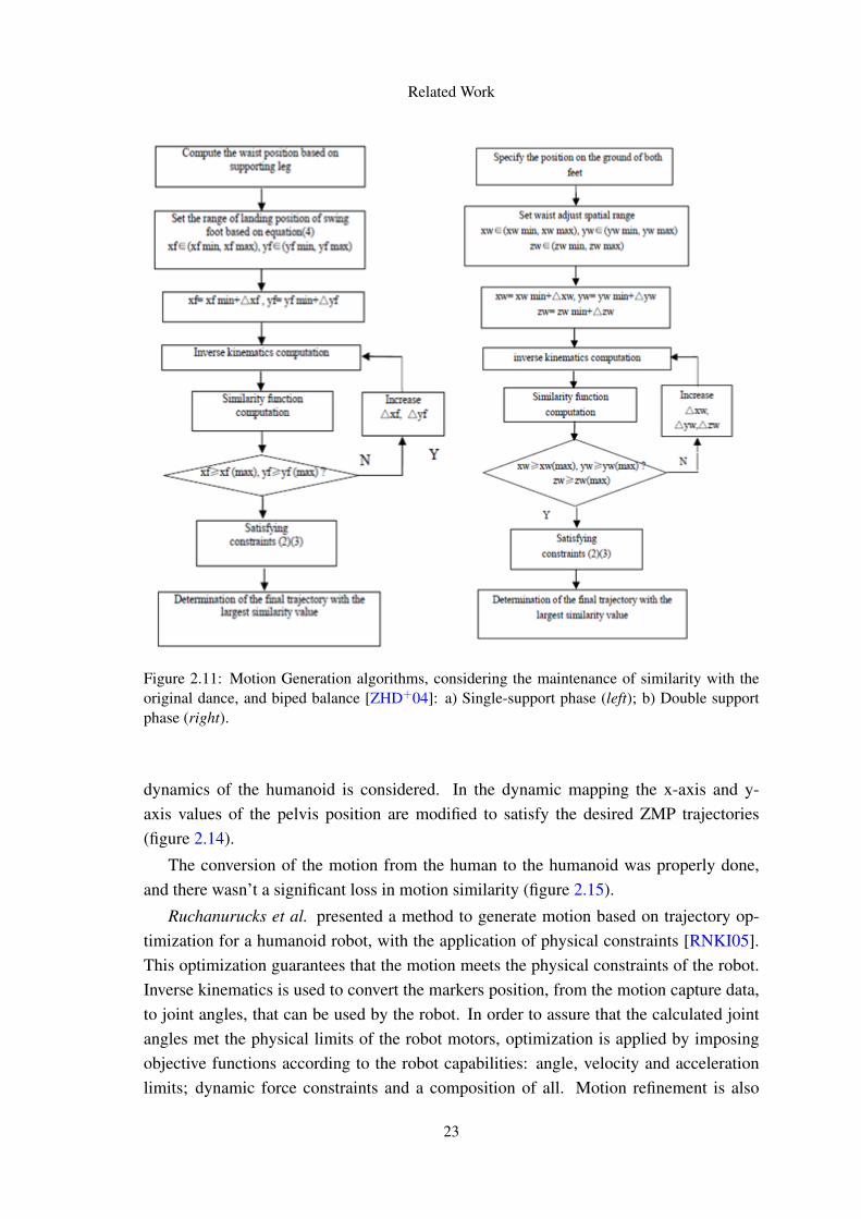
Zhao et al. uses kinematics mapping to translate the captured motion data to thehumanoid morphology, while satisfying the humanoid constraints [ZHD+04]. The use ofsimilarity functions helps the mapping of the motion, keeping the motion as close as thehuman but also ensuring that the physical constraints of the humanoid are not violated.This similarity function is maximal when the joint angles of the humanoid are equal tothe ones of the human actor. For the upper limbs, the constraints include mainly the jointrotational range and the different number of DoFs. For the lower limbs, the ground contactconditions are critical. The algorithm for generate the movements starts by computingthe robot waist position and then proceeds to the maintenance of the robot balance byrecurring to 2 different algorithms, depending on the number of feet on the ground: analgorithm to the single-support phase and an algorithm for the double support phase, asdescribed in figure 2.11.
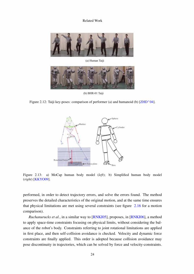
Even by satisfying the kinematics constraints, the stability of the robot cannot be guar-anteed, so the hip trajectory is modified to satisfy a constraint based on the ZMP criterion.To demonstrate the method the humanoid robot performed Chinese Kongfu “Taiji” (fig-ure 2.12).
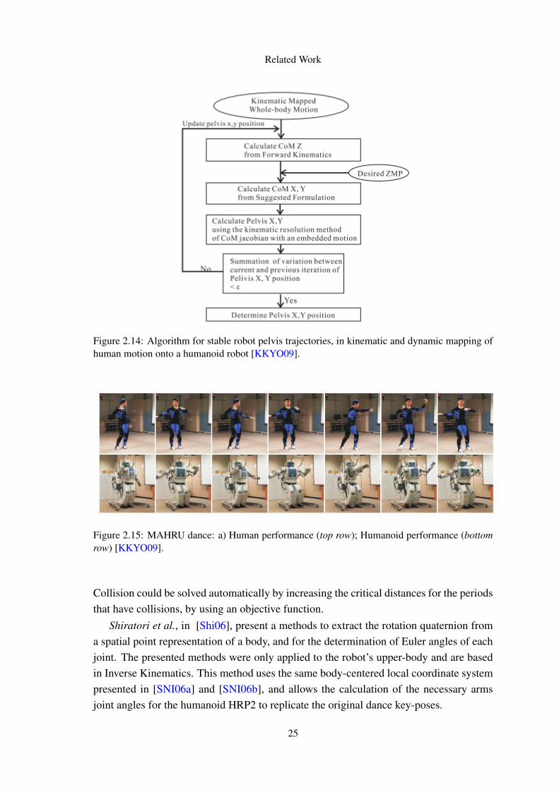
Kim et al. introduce a simplified human model to obtain a ZMP trajectory of a humanbased on the marker trajectories of motion capture data [KKYO09]. From the motioncapture data some of the parameters are extracted to build a simplified human body withcylinders, spheres or boxes (figure 2.13). The body parts are connected as a chain, eachhaving 3 DOF. In order to find the unknown parameters for building the body optimizationis used, by minimizing the error between the ZMP trajectories obtained from the capturedata, the reaction data, and the approximated ZMP trajectories of the simplified humanmodel.
Kinematic and dynamic mapping is also used to generate the humanoid motion. In thekinematic mapping, the motion for the upper-body is created using Inverse Kinematicsand optimization. The arms are scaled to resolve the geometric difference between therobot arms and the human arms. A cubic spline interpolation is used to smooth the discretejoint trajectory, providing position and velocity values of joints as references during real-time control. The mapping of lower-body deals mostly with the feet and pelvis motions.Another important step is the need to modify and scale the ZMP trajectories to avoid thatthe humanoid fall down. After this, the dynamic mapping is applied. The ZMP trajectorymay still be inconsistent with the lower and upper-body motions, since no constraint on
22
Related Work
Figure 2.11: Motion Generation algorithms, considering the maintenance of similarity with theoriginal dance, and biped balance [ZHD+04]: a) Single-support phase (left); b) Double supportphase (right).
dynamics of the humanoid is considered. In the dynamic mapping the x-axis and y-axis values of the pelvis position are modified to satisfy the desired ZMP trajectories(figure 2.14).
The conversion of the motion from the human to the humanoid was properly done,and there wasn’t a significant loss in motion similarity (figure 2.15).
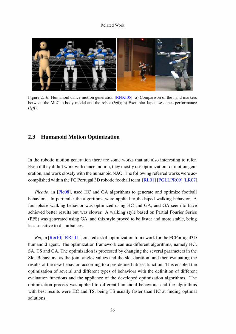
Ruchanurucks et al. presented a method to generate motion based on trajectory op-timization for a humanoid robot, with the application of physical constraints [RNKI05].This optimization guarantees that the motion meets the physical constraints of the robot.Inverse kinematics is used to convert the markers position, from the motion capture data,to joint angles, that can be used by the robot. In order to assure that the calculated jointangles met the physical limits of the robot motors, optimization is applied by imposingobjective functions according to the robot capabilities: angle, velocity and accelerationlimits; dynamic force constraints and a composition of all. Motion refinement is also
23
Related Work
Figure 2.12: Taiji key-poses: comparison of performer (a) and humanoid (b) [ZHD+04].
Figure 2.13: a) MoCap human body model (left); b) Simplified human body model(right) [KKYO09].
performed, in order to detect trajectory errors, and solve the errors found. The methodpreserves the detailed characteristics of the original motion, and at the same time ensuresthat physical limitations are met using several constraints (see figure 2.16 for a motioncomparison).
Ruchanurucks et al., in a similar way to [RNKI05], proposes, in [RNKI06], a methodto apply space-time constraints focusing on physical limits, without considering the bal-ance of the robot’s body. Constraints referring to joint rotational limitations are appliedin first place, and then self-collision avoidance is checked. Velocity and dynamic forceconstraints are finally applied. This order is adopted because collision avoidance maypose discontinuity in trajectories, which can be solved by force and velocity-constraints.
24
Related Work
Figure 2.14: Algorithm for stable robot pelvis trajectories, in kinematic and dynamic mapping ofhuman motion onto a humanoid robot [KKYO09].
Figure 2.15: MAHRU dance: a) Human performance (top row); Humanoid performance (bottomrow) [KKYO09].
Collision could be solved automatically by increasing the critical distances for the periodsthat have collisions, by using an objective function.
Shiratori et al., in [Shi06], present a methods to extract the rotation quaternion froma spatial point representation of a body, and for the determination of Euler angles of eachjoint. The presented methods were only applied to the robot’s upper-body and are basedin Inverse Kinematics. This method uses the same body-centered local coordinate systempresented in [SNI06a] and [SNI06b], and allows the calculation of the necessary armsjoint angles for the humanoid HRP2 to replicate the original dance key-poses.
25
Related Work
Figure 2.16: Humanoid dance motion generation [RNKI05]: a) Comparison of the hand markersbetween the MoCap body model and the robot (left); b) Exemplar Japanese dance performance(left).
2.3 Humanoid Motion Optimization
In the robotic motion generation there are some works that are also interesting to refer.Even if they didn’t work with dance motion, they mostly use optimization for motion gen-eration, and work closely with the humanoid NAO. The following referred works were ac-complished within the FC Portugal 3D robotic football team [RL01] [PGLLPR09] [LR07].
Picado, in [Pic08], used HC and GA algorithms to generate and optimize footballbehaviors. In particular the algorithms were applied to the biped walking behavior. Afour-phase walking behavior was optimized using HC and GA, and GA seem to haveachieved better results but was slower. A walking style based on Partial Fourier Series(PFS) was generated using GA, and this style proved to be faster and more stable, beingless sensitive to disturbances.
Rei, in [Rei10] [RRL11], created a skill optimization framework for the FCPortugal3Dhumanoid agent. The optimization framework can use different algorithms, namely HC,SA, TS and GA. The optimization is processed by changing the several parameters in theSlot Behaviors, as the joint angles values and the slot duration, and then evaluating theresults of the new behavior, according to a pre-defined fitness function. This enabled theoptimization of several and different types of behaviors with the definition of differentevaluation functions and the appliance of the developed optimization algorithms. Theoptimization process was applied to different humanoid behaviors, and the algorithmswith best results were HC and TS, being TS usually faster than HC at finding optimalsolutions.
26
Related Work
2.4 Conclusions and Proposal
With the analysis of the literature some lessons can be learned. In first place, we can seemany limitations, or problems, with some of the presented approaches. The followingtable 2.1 presents an overview of some of the most important aspects of the presentedworks, concerning this thesis proposal.
Some of this methods lack in music perception [NOI+05], while others take it inconsideration but only generate motion to animated platforms [OCFT+08], [NOI+05],[SNI06a], [SNI06b], [SKNI07], [KPS03].
There are few methods that labored the generation of full body humanoid motions.[SKNI07] and [KKYO09] only apply their methods to upper-body and [OSKI10] onlygenerates legs motion. Although by combining some methods, [SKNI07] and [OSKI10],we could get full-body robotic motions, they have only been applied to a dance style andfurther experiments with different dance performances are needed.
On the other side, the literature also gives a good insight on the various problemsand challenges that lay ahead, and that need to be addressed, and solved, to successfullycreate and present the proposed solution. These challenges are various: the analysis of themotion data must allow extracting meaningful information, but also must allow that themotion can keep some variability; the anatomic differences between the humanoid and thehuman actor need careful transformations, and the motion/music relationship must alsobe addressed. In the motion generation, the robot physical constraints, the balance of thehumanoid, the necessity to avoid self-collisions, and the maintenance of the motion-musicsynchrony are the most important factors towards this goal.
For the development of further work, we shall base our motion analysis and motiongeneration on [ONG+10], taking advantage of the point cloud representation, and theparameterization and maneuverability that it offers and also the dance variability that thisrepresentation can translate. For extending the work to the robotics area, and to enable thereproduction of the generated key-poses, we shall focus on the appliance of the methodpresented in [Shi06]. With the extraction of the humanoid joint angles, Slot Behaviorscan be created in SimSpark and the humanoid may reproduce the desired poses. Finally,for improving and refining the generated poses in the humanoid, in order to increase itssimilarity with the synthesized poses (resulting from the motion synthesis phase), and,consequently, with the real human dance performance, we shall apply optimization, re-curring to the framework presented in [Rei10], by using the TS algorithm. Ultimately,the actual motion-music synchrony shall be assured by the adopted spatiotemporal rep-resentation of the original dance performance [ONG+10], and shall be replicated byinterpolating the generated key-poses with the transition timings given by this represen-tation.
27
Related Work
Table 2.1: Overview related work, according to each identified problem to this thesis proposal(NA refers to Not Applied).
Approach Dance MotionAnalysis
Motion/MusicSynchrony
Motion Synthe-sis and Genera-tion
MorphologicalAdaptation andOptimization
Shiratori etal [SNI06a]
Music features(rhythm andintensity) corre-lated with motionfeatures
Music features(rhythm andintensity) corre-lated with motionfeatures
Motion SegmentInterpolation
NA
Shiratori etal [SNI06b]
Motion fea-tures (key frameand intensity)extraction
Music features(music beats,degree of cordchanges andintensity) corre-lated with motionfeatures
Motion Graph +third order inter-polation of bodylinks
NA
Shiratori etal [SKNI07][OSKI10]
Temporal scalingtechniques +key-poses formaintaining thedance motionshape at differentmusic speeds
NA B-spline In-terpolation[SKNI07] + Cu-bic PolynomialInterpolation andInverse Kinemat-ics [OSKI10]
ConsideredJoint constraints[SKNI07] +ZMP verification[OSKI10]
Kim et al[KPS03]
Motion Beats:Moments ofrapid change inmotion
Incrementaltime-wrapping
Motion Graph Real time Mor-phological Adap-tation
Ruchanuruckset al[RNKI05][RNKI06]
NA NA Inverse Kinemat-ics
Objective Func-tions [RNKI05]+ SequentialConstraints[RNKI06]
Zhao et al[ZHD+04]
NA NA Kinematics Map-ping
Similarity func-tions + Physicalconstraints
Nagata et al[NOI+05]
Extraction ofshoulders andhips movements
NA Motion Graph+ joints linearinterpolation byline-blending
NA
28
Chapter 3
Humanizing Robot Dance Movements
In this section the methodology used in order to archive the proposed goal will be de-scribed.
The implementation will be based on the method used in [ONG+10] to analyze themotion capture data. This analyze shall enable the extraction of the dance fundamentalkey-poses and their point cloud representation. With the information for each joint in eachmetric class, adaption will be done over the point cloud representation, so that it fits thetarget robot morphology. After this adaption, the key-poses will be randomly generated[ONG+11] (process illustrated in figure 3.1), and the angles between the body segmentsextracted. Finally the poses will be reproduced onto the humanoid robot.
Having robot performing the poses generated, optimization will be allied to increasethe similarity of the motion generated to a robot model and the motion performed by therobot. Finally, the motion will be generated by interpolation of the key poses with thecalculated interval between the poses.
3.1 Dance Motion Analysis
The dance motion analysis stage is based on the approach presented in [ONG+10]. Assuch, we recurred to the same dance sequences of Afro-Brazilian samba, which werecaptured with a MoCap system, and synchronized to the same genre of samba music(manually annotated by experts). Upon these, we also applied the TGA (TopologicalGesture Analysis) method [NL10] for building a spatiotemporal representation of theoriginal dance movement in relation to the respective music temporal structure (musicalmeter).
29
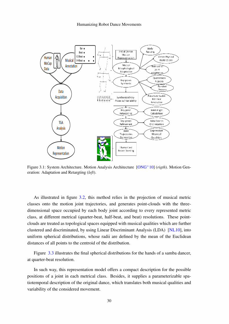
Humanizing Robot Dance Movements
Figure 3.1: System Architecture. Motion Analysis Architecture [ONG+10] (rigth). Motion Gen-eration: Adaptation and Retargting (left).
As illustrated in figure 3.2, this method relies in the projection of musical metricclasses onto the motion joint trajectories, and generates point-clouds with the three-dimensional space occupied by each body joint according to every represented metricclass, at different metrical (quarter-beat, half-beat, and beat) resolutions. These point-clouds are treated as topological spaces equipped with musical qualities which are furtherclustered and discriminated, by using Linear Discriminant Analysis (LDA) [NL10], intouniform spherical distributions, whose radii are defined by the mean of the Euclideandistances of all points to the centroid of the distribution.
Figure 3.3 illustrates the final spherical distributions for the hands of a samba dancer,at quarter-beat resolution.
In such way, this representation model offers a compact description for the possiblepositions of a joint in each metrical class. Besides, it supplies a parameterizable spa-tiotemporal description of the original dance, which translates both musical qualities andvariability of the considered movement.
30
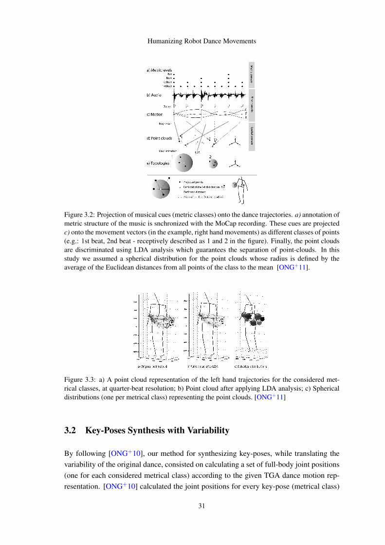
Humanizing Robot Dance Movements
Figure 3.2: Projection of musical cues (metric classes) onto the dance trajectories. a) annotation ofmetric structure of the music is snchronized with the MoCap recording. These cues are projectedc) onto the movement vectors (in the example, right hand movements) as different classes of points(e.g.: 1st beat, 2nd beat - receptively described as 1 and 2 in the figure). Finally, the point cloudsare discriminated using LDA analysis which guarantees the separation of point-clouds. In thisstudy we assumed a spherical distribution for the point clouds whose radius is defined by theaverage of the Euclidean distances from all points of the class to the mean [ONG+11].
Figure 3.3: a) A point cloud representation of the left hand trajectories for the considered met-rical classes, at quarter-beat resolution; b) Point cloud after applying LDA analysis; c) Sphericaldistributions (one per metrical class) representing the point clouds. [ONG+11]
3.2 Key-Poses Synthesis with Variability
By following [ONG+10], our method for synthesizing key-poses, while translating thevariability of the original dance, consisted on calculating a set of full-body joint positions(one for each considered metrical class) according to the given TGA dance motion rep-resentation. [ONG+10] calculated the joint positions for every key-pose (metrical class)
31
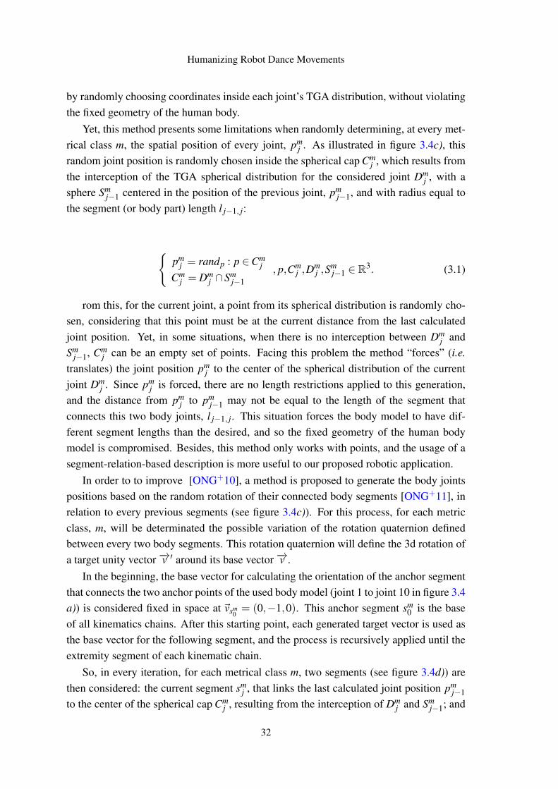
Humanizing Robot Dance Movements
by randomly choosing coordinates inside each joint’s TGA distribution, without violatingthe fixed geometry of the human body.
Yet, this method presents some limitations when randomly determining, at every met-rical class m, the spatial position of every joint, pm
j . As illustrated in figure 3.4c), thisrandom joint position is randomly chosen inside the spherical cap Cm
j , which results fromthe interception of the TGA spherical distribution for the considered joint Dm
j , with asphere Sm
j−1 centered in the position of the previous joint, pmj−1, and with radius equal to
the segment (or body part) length l j−1, j:
{pm
j = randp : p ∈Cmj
Cmj = Dm
j ∩Smj−1
, p,Cmj ,D
mj ,S
mj−1 ∈ R3. (3.1)
rom this, for the current joint, a point from its spherical distribution is randomly cho-sen, considering that this point must be at the current distance from the last calculatedjoint position. Yet, in some situations, when there is no interception between Dm
j andSm
j−1, Cmj can be an empty set of points. Facing this problem the method “forces” (i.e.
translates) the joint position pmj to the center of the spherical distribution of the current
joint Dmj . Since pm
j is forced, there are no length restrictions applied to this generation,and the distance from pm
j to pmj−1 may not be equal to the length of the segment that
connects this two body joints, l j−1, j. This situation forces the body model to have dif-ferent segment lengths than the desired, and so the fixed geometry of the human bodymodel is compromised. Besides, this method only works with points, and the usage of asegment-relation-based description is more useful to our proposed robotic application.
In order to to improve [ONG+10], a method is proposed to generate the body jointspositions based on the random rotation of their connected body segments [ONG+11], inrelation to every previous segments (see figure 3.4c)). For this process, for each metricclass, m, will be determinated the possible variation of the rotation quaternion definedbetween every two body segments. This rotation quaternion will define the 3d rotation ofa target unity vector −→v ′ around its base vector −→v .
In the beginning, the base vector for calculating the orientation of the anchor segmentthat connects the two anchor points of the used body model (joint 1 to joint 10 in figure 3.4a)) is considered fixed in space at ~vsm
0= (0,−1,0). This anchor segment sm
0 is the baseof all kinematics chains. After this starting point, each generated target vector is used asthe base vector for the following segment, and the process is recursively applied until theextremity segment of each kinematic chain.
So, in every iteration, for each metrical class m, two segments (see figure 3.4d)) arethen considered: the current segment sm
j , that links the last calculated joint position pmj−1
to the center of the spherical cap Cmj , resulting from the interception of Dm
j and Smj−1; and
32
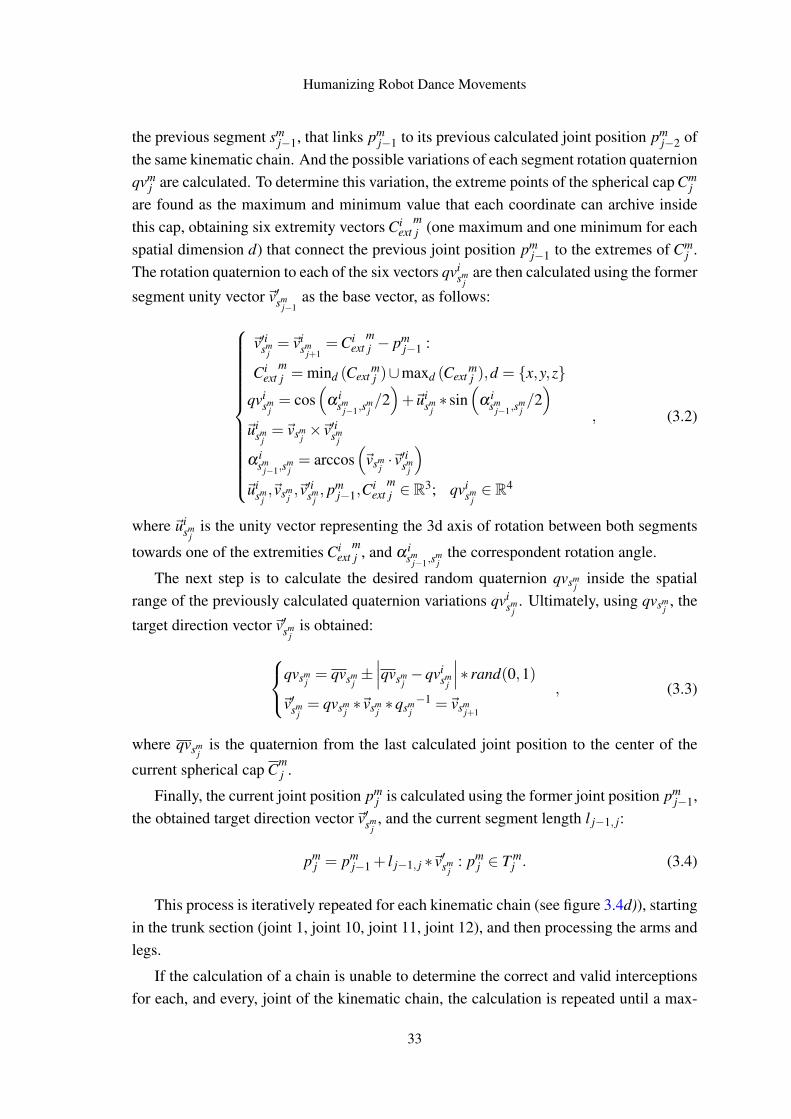
Humanizing Robot Dance Movements
the previous segment smj−1, that links pm
j−1 to its previous calculated joint position pmj−2 of
the same kinematic chain. And the possible variations of each segment rotation quaternionqvm
j are calculated. To determine this variation, the extreme points of the spherical cap Cmj
are found as the maximum and minimum value that each coordinate can archive insidethis cap, obtaining six extremity vectors Ci
extmj (one maximum and one minimum for each
spatial dimension d) that connect the previous joint position pmj−1 to the extremes of Cm
j .The rotation quaternion to each of the six vectors qvi
smj
are then calculated using the former
segment unity vector~v′smj−1
as the base vector, as follows:
~v′ismj=~vi
smj+1
=Ciext
mj − pm
j−1 :
Ciext
mj = mind (Cext
mj )∪maxd (Cext
mj ),d = {x,y,z}
qvism
j= cos
(α i
smj−1,s
mj/2)+~ui
smj∗ sin
(α i
smj−1,s
mj/2)
~uism
j=~vsm
j×~v′ism
j
α ism
j−1,smj= arccos
(~vsm
j·~v′ism
j
)~ui
smj,~vsm
j,~v′ism
j, pm
j−1,Ciext
mj ∈ R3; qvi
smj∈ R4
, (3.2)
where ~uism
jis the unity vector representing the 3d axis of rotation between both segments
towards one of the extremities Ciext
mj , and α i
smj−1,s
mj
the correspondent rotation angle.
The next step is to calculate the desired random quaternion qvsmj
inside the spatialrange of the previously calculated quaternion variations qvi
smj. Ultimately, using qvsm
j, the
target direction vector~v′smj
is obtained:
qvsmj= qvsm
j±∣∣∣qvsm
j−qvi
smj
∣∣∣∗ rand(0,1)
~v′smj= qvsm
j∗~vsm
j∗qsm
j−1 =~vsm
j+1
, (3.3)
where qvsmj
is the quaternion from the last calculated joint position to the center of the
current spherical cap Cmj .
Finally, the current joint position pmj is calculated using the former joint position pm
j−1,the obtained target direction vector~v′sm
j, and the current segment length l j−1, j:
pmj = pm
j−1 + l j−1, j ∗~v′smj
: pmj ∈ T m
j . (3.4)
This process is iteratively repeated for each kinematic chain (see figure 3.4d)), startingin the trunk section (joint 1, joint 10, joint 11, joint 12), and then processing the arms andlegs.
If the calculation of a chain is unable to determine the correct and valid interceptionsfor each, and every, joint of the kinematic chain, the calculation is repeated until a max-
33
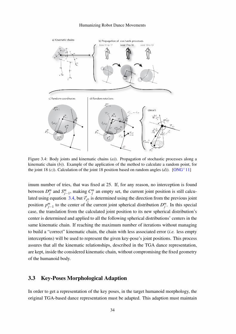
Humanizing Robot Dance Movements
Figure 3.4: Body joints and kinematic chains (a)). Propagation of stochastic processes along akinematic chain (b)). Example of the application of the method to calculate a random point, forthe joint 18 (c)). Calculation of the joint 18 position based on random angles (d)). [ONG+11]
imum number of tries, that was fixed at 25. If, for any reason, no interception is foundbetween Dm
j and Smj−1, making Cm
j an empty set, the current joint position is still calcu-lated using equation 3.4, but~v′sm
jis determined using the direction from the previous joint
position pmj−1 to the center of the current joint spherical distribution Dm
j . In this specialcase, the translation from the calculated joint position to its new spherical distribution’scenter is determined and applied to all the following spherical distributions’ centers in thesame kinematic chain. If reaching the maximum number of iterations without managingto build a “correct” kinematic chain, the chain with less associated error (i.e. less emptyinterceptions) will be used to represent the given key-pose’s joint positions. This processassures that all the kinematic relationships, described in the TGA dance representation,are kept, inside the considered kinematic chain, without compromising the fixed geometryof the humanoid body.
3.3 Key-Poses Morphological Adaption
In order to get a representation of the key poses, in the target humanoid morphology, theoriginal TGA-based dance representation must be adapted. This adaption must maintain
34
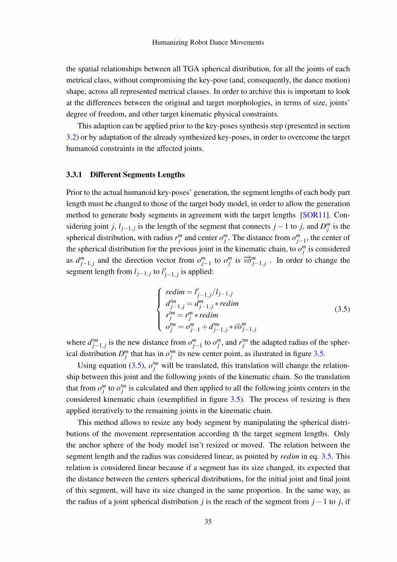
Humanizing Robot Dance Movements
the spatial relationships between all TGA spherical distribution, for all the joints of eachmetrical class, without compromising the key-pose (and, consequently, the dance motion)shape, across all represented metrical classes. In order to archive this is important to lookat the differences between the original and target morphologies, in terms of size, joints’degree of freedom, and other target kinematic physical constraints.
This adaption can be applied prior to the key-poses synthesis step (presented in section3.2) or by adaptation of the already synthesized key-poses, in order to overcome the targethumanoid constraints in the affected joints.
3.3.1 Different Segments Lengths
Prior to the actual humanoid key-poses’ generation, the segment lengths of each body partlength must be changed to those of the target body model, in order to allow the generationmethod to generate body segments in agreement with the target lengths [SOR11]. Con-sidering joint j, l j−1, j is the length of the segment that connects j−1 to j, and Dm
j is thespherical distribution, with radius rm
j and center omj . The distance from om
j−1, the center ofthe spherical distribution for the previous joint in the kinematic chain, to om
j is consideredas dm
j−1, j and the direction vector from omj−1 to om
j is −→vomj−1, j . In order to change the
segment length from l j−1, j to l′j−1, j is applied:redim = l′j−1, j/l j−1, j
d′mj−1, j = dmj−1, j ∗ redim
r′mj = rmj ∗ redim
o′mj = omj−1 +d′mj−1, j ∗ ~vom
j−1, j
(3.5)
where d′mj−1, j is the new distance from omj−1 to om
j , and r′mj the adapted radius of the spher-ical distribution Dm
j that has in o′mj its new center point, as ilustrated in figure 3.5.Using equation (3.5), o′mj will be translated, this translation will change the relation-
ship between this joint and the following joints of the kinematic chain. So the translationthat from om
j to o′mj is calculated and then applied to all the following joints centers in theconsidered kinematic chain (exemplified in figure 3.5). The process of resizing is thenapplied iteratively to the remaining joints in the kinematic chain.
This method allows to resize any body segment by manipulating the spherical distri-butions of the movement representation according th the target segment lengths. Onlythe anchor sphere of the body model isn’t resized or moved. The relation between thesegment length and the radius was considered linear, as pointed by redim in eq. 3.5. Thisrelation is considered linear because if a segment has its size changed, its expected thatthe distance between the centers spherical distributions, for the initial joint and final jointof this segment, will have its size changed in the same proportion. In the same way, asthe radius of a joint spherical distribution j is the reach of the segment from j−1 to j, if
35
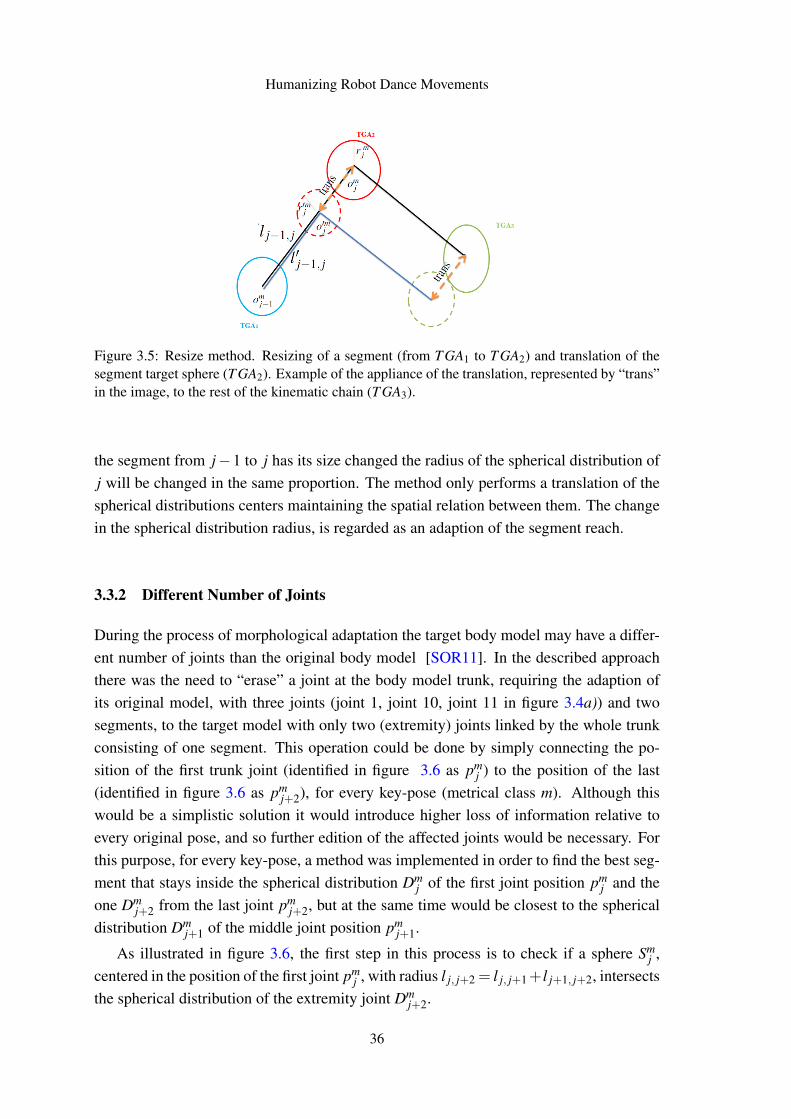
Humanizing Robot Dance Movements
Figure 3.5: Resize method. Resizing of a segment (from T GA1 to T GA2) and translation of thesegment target sphere (T GA2). Example of the appliance of the translation, represented by “trans”in the image, to the rest of the kinematic chain (T GA3).
the segment from j−1 to j has its size changed the radius of the spherical distribution ofj will be changed in the same proportion. The method only performs a translation of thespherical distributions centers maintaining the spatial relation between them. The changein the spherical distribution radius, is regarded as an adaption of the segment reach.
3.3.2 Different Number of Joints
During the process of morphological adaptation the target body model may have a differ-ent number of joints than the original body model [SOR11]. In the described approachthere was the need to “erase” a joint at the body model trunk, requiring the adaption ofits original model, with three joints (joint 1, joint 10, joint 11 in figure 3.4a)) and twosegments, to the target model with only two (extremity) joints linked by the whole trunkconsisting of one segment. This operation could be done by simply connecting the po-sition of the first trunk joint (identified in figure 3.6 as pm
j ) to the position of the last(identified in figure 3.6 as pm
j+2), for every key-pose (metrical class m). Although thiswould be a simplistic solution it would introduce higher loss of information relative toevery original pose, and so further edition of the affected joints would be necessary. Forthis purpose, for every key-pose, a method was implemented in order to find the best seg-ment that stays inside the spherical distribution Dm
j of the first joint position pmj and the
one Dmj+2 from the last joint pm
j+2, but at the same time would be closest to the sphericaldistribution Dm
j+1 of the middle joint position pmj+1.
As illustrated in figure 3.6, the first step in this process is to check if a sphere Smj ,
centered in the position of the first joint pmj , with radius l j, j+2 = l j, j+1+ l j+1, j+2, intersects
the spherical distribution of the extremity joint Dmj+2.
36
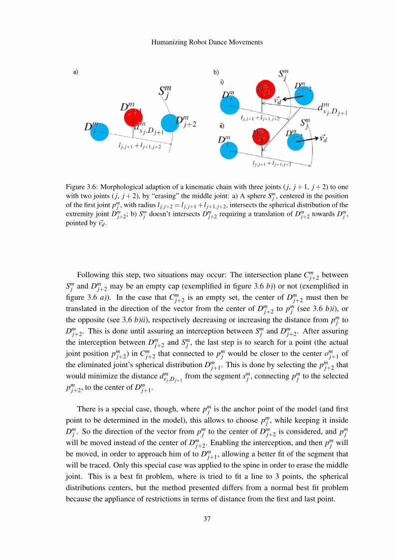
Humanizing Robot Dance Movements
Figure 3.6: Morphological adaption of a kinematic chain with three joints ( j, j+1, j+2) to onewith two joints ( j, j+2), by “erasing” the middle joint: a) A sphere Sm
j , centered in the positionof the first joint pm
j , with radius l j, j+2 = l j, j+1+ l j+1, j+2, intersects the spherical distribution of theextremity joint Dm
j+2; b) Smj doesn’t intersects Dm
j+2 requiring a translation of Dmj+2 towards Dm
j ,pointed by ~vd .
Following this step, two situations may occur: The intersection plane Cmj+2 between
Smj and Dm
j+2 may be an empty cap (exemplified in figure 3.6 b)) or not (exemplified infigure 3.6 a)). In the case that Cm
j+2 is an empty set, the center of Dmj+2 must then be
translated in the direction of the vector from the center of Dmj+2 to pm
j (see 3.6 b)i), orthe opposite (see 3.6 b)ii), respectively decreasing or increasing the distance from pm
j toDm
j+2. This is done until assuring an interception between Smj and Dm
j+2. After assuringthe interception between Dm
j+2 and Smj , the last step is to search for a point (the actual
joint position pmj+2) in Cm
j+2 that connected to pmj would be closer to the center om
j+1 ofthe eliminated joint’s spherical distribution Dm
j+1. This is done by selecting the pmj+2 that
would minimize the distance dms j,D j+1
from the segment smj , connecting pm
j to the selectedpm
j+2, to the center of Dmj+1.
There is a special case, though, where pmj is the anchor point of the model (and first
point to be determined in the model), this allows to choose pmj , while keeping it inside
Dmj . So the direction of the vector from pm
j to the center of Dmj+2 is considered, and pm
j
will be moved instead of the center of Dmj+2. Enabling the interception, and then pm
j willbe moved, in order to approach him of to Dm
j+1, allowing a better fit of the segment thatwill be traced. Only this special case was applied to the spine in order to erase the middlejoint. This is a best fit problem, where is tried to fit a line to 3 points, the sphericaldistributions centers, but the method presented differs from a normal best fit problembecause the appliance of restrictions in terms of distance from the first and last point.
37
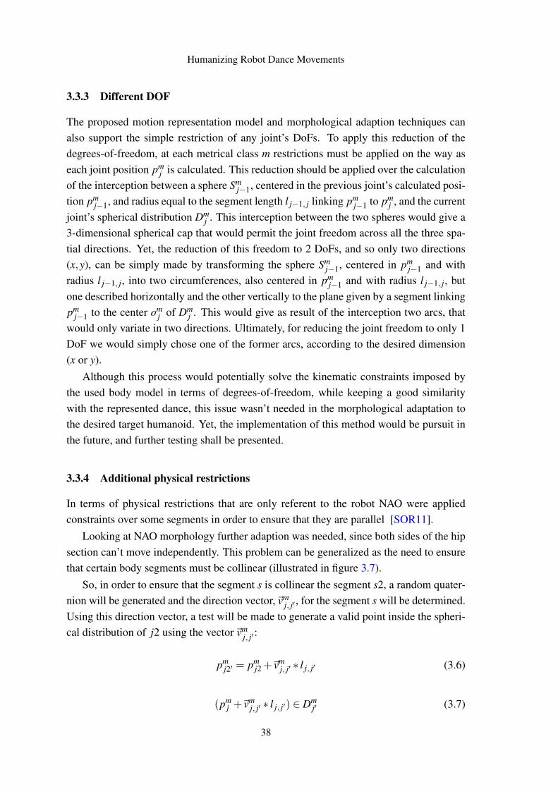
Humanizing Robot Dance Movements
3.3.3 Different DOF
The proposed motion representation model and morphological adaption techniques canalso support the simple restriction of any joint’s DoFs. To apply this reduction of thedegrees-of-freedom, at each metrical class m restrictions must be applied on the way aseach joint position pm
j is calculated. This reduction should be applied over the calculationof the interception between a sphere Sm
j−1, centered in the previous joint’s calculated posi-tion pm
j−1, and radius equal to the segment length l j−1, j linking pmj−1 to pm
j , and the currentjoint’s spherical distribution Dm
j . This interception between the two spheres would give a3-dimensional spherical cap that would permit the joint freedom across all the three spa-tial directions. Yet, the reduction of this freedom to 2 DoFs, and so only two directions(x,y), can be simply made by transforming the sphere Sm
j−1, centered in pmj−1 and with
radius l j−1, j, into two circumferences, also centered in pmj−1 and with radius l j−1, j, but
one described horizontally and the other vertically to the plane given by a segment linkingpm
j−1 to the center omj of Dm
j . This would give as result of the interception two arcs, thatwould only variate in two directions. Ultimately, for reducing the joint freedom to only 1DoF we would simply chose one of the former arcs, according to the desired dimension(x or y).
Although this process would potentially solve the kinematic constraints imposed bythe used body model in terms of degrees-of-freedom, while keeping a good similaritywith the represented dance, this issue wasn’t needed in the morphological adaptation tothe desired target humanoid. Yet, the implementation of this method would be pursuit inthe future, and further testing shall be presented.
3.3.4 Additional physical restrictions
In terms of physical restrictions that are only referent to the robot NAO were appliedconstraints over some segments in order to ensure that they are parallel [SOR11].
Looking at NAO morphology further adaption was needed, since both sides of the hipsection can’t move independently. This problem can be generalized as the need to ensurethat certain body segments must be collinear (illustrated in figure 3.7).
So, in order to ensure that the segment s is collinear the segment s2, a random quater-nion will be generated and the direction vector,~vm
j, j′ , for the segment s will be determined.Using this direction vector, a test will be made to generate a valid point inside the spheri-cal distribution of j2 using the vector~vm
j, j′:
pmj2′ = pm
j2 +~vmj, j′ ∗ l j, j′ (3.6)
(pmj +~vm
j, j′ ∗ l j, j′) ∈ Dmj′ (3.7)
38
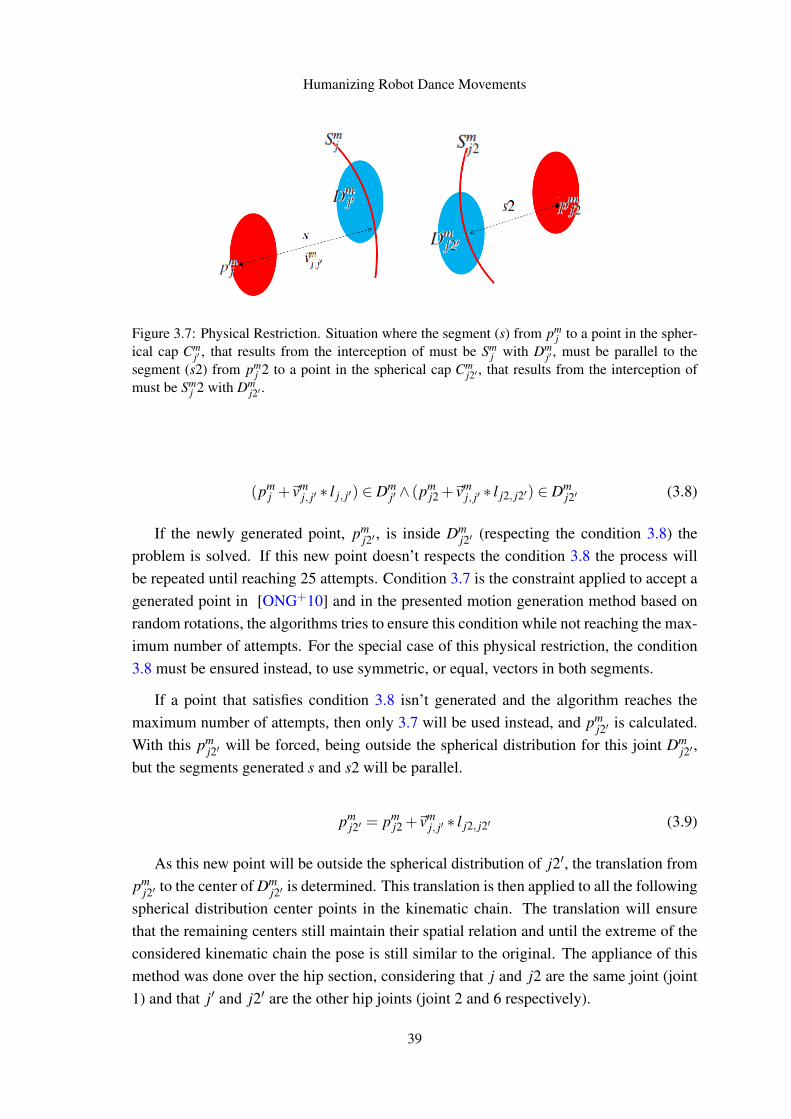
Humanizing Robot Dance Movements
Figure 3.7: Physical Restriction. Situation where the segment (s) from pmj to a point in the spher-
ical cap Cmj′ , that results from the interception of must be Sm
j with Dmj′ , must be parallel to the
segment (s2) from pmj 2 to a point in the spherical cap Cm
j2′ , that results from the interception ofmust be Sm
j 2 with Dmj2′ .
(pmj +~vm
j, j′ ∗ l j, j′) ∈ Dmj′ ∧ (pm
j2 +~vmj, j′ ∗ l j2, j2′) ∈ Dm
j2′ (3.8)
If the newly generated point, pmj2′ , is inside Dm
j2′ (respecting the condition 3.8) theproblem is solved. If this new point doesn’t respects the condition 3.8 the process willbe repeated until reaching 25 attempts. Condition 3.7 is the constraint applied to accept agenerated point in [ONG+10] and in the presented motion generation method based onrandom rotations, the algorithms tries to ensure this condition while not reaching the max-imum number of attempts. For the special case of this physical restriction, the condition3.8 must be ensured instead, to use symmetric, or equal, vectors in both segments.
If a point that satisfies condition 3.8 isn’t generated and the algorithm reaches themaximum number of attempts, then only 3.7 will be used instead, and pm
j2′ is calculated.With this pm
j2′ will be forced, being outside the spherical distribution for this joint Dmj2′ ,
but the segments generated s and s2 will be parallel.
pmj2′ = pm
j2 +~vmj, j′ ∗ l j2, j2′ (3.9)
As this new point will be outside the spherical distribution of j2′, the translation frompm
j2′ to the center of Dmj2′ is determined. This translation is then applied to all the following
spherical distribution center points in the kinematic chain. The translation will ensurethat the remaining centers still maintain their spatial relation and until the extreme of theconsidered kinematic chain the pose is still similar to the original. The appliance of thismethod was done over the hip section, considering that j and j2 are the same joint (joint1) and that j′ and j2′ are the other hip joints (joint 2 and 6 respectively).
39
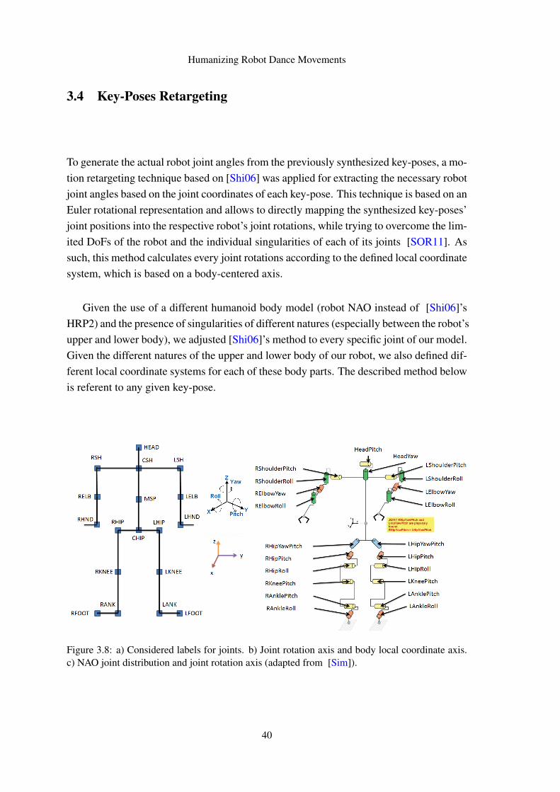
Humanizing Robot Dance Movements
3.4 Key-Poses Retargeting
To generate the actual robot joint angles from the previously synthesized key-poses, a mo-tion retargeting technique based on [Shi06] was applied for extracting the necessary robotjoint angles based on the joint coordinates of each key-pose. This technique is based on anEuler rotational representation and allows to directly mapping the synthesized key-poses’joint positions into the respective robot’s joint rotations, while trying to overcome the lim-ited DoFs of the robot and the individual singularities of each of its joints [SOR11]. Assuch, this method calculates every joint rotations according to the defined local coordinatesystem, which is based on a body-centered axis.
Given the use of a different humanoid body model (robot NAO instead of [Shi06]’sHRP2) and the presence of singularities of different natures (especially between the robot’supper and lower body), we adjusted [Shi06]’s method to every specific joint of our model.Given the different natures of the upper and lower body of our robot, we also defined dif-ferent local coordinate systems for each of these body parts. The described method belowis referent to any given key-pose.
Figure 3.8: a) Considered labels for joints. b) Joint rotation axis and body local coordinate axis.c) NAO joint distribution and joint rotation axis (adapted from [Sim]).
40
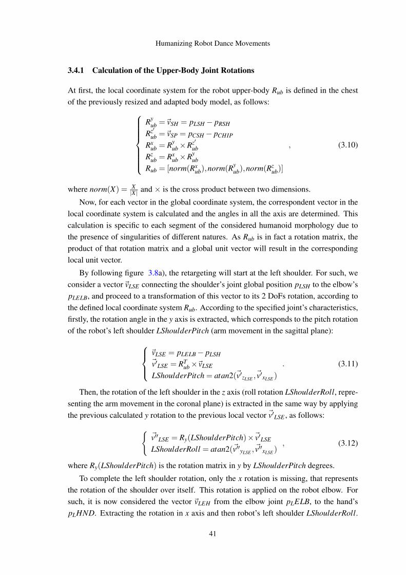
Humanizing Robot Dance Movements
3.4.1 Calculation of the Upper-Body Joint Rotations
At first, the local coordinate system for the robot upper-body Rub is defined in the chestof the previously resized and adapted body model, as follows:
Ryub =~vSH = pLSH− pRSH
Rz′ub =~vSP = pCSH− pCHIP
Rxub = Ry
ub×Rz′ub
Rzub = Rx
ub×Ryub
Rub = [norm(Rxub),norm(Ry
ub),norm(Rzub)]
, (3.10)
where norm(X) = X|X | and × is the cross product between two dimensions.
Now, for each vector in the global coordinate system, the correspondent vector in thelocal coordinate system is calculated and the angles in all the axis are determined. Thiscalculation is specific to each segment of the considered humanoid morphology due tothe presence of singularities of different natures. As Rub is in fact a rotation matrix, theproduct of that rotation matrix and a global unit vector will result in the correspondinglocal unit vector.
By following figure 3.8a), the retargeting will start at the left shoulder. For such, weconsider a vector~vLSE connecting the shoulder’s joint global position pLSH to the elbow’spLELB, and proceed to a transformation of this vector to its 2 DoFs rotation, according tothe defined local coordinate system Rub. According to the specified joint’s characteristics,firstly, the rotation angle in the y axis is extracted, which corresponds to the pitch rotationof the robot’s left shoulder LShoulderPitch (arm movement in the sagittal plane):
~vLSE = pLELB− pLSH~v′LSE = RT
ub×~vLSE
LShoulderPitch = atan2(~v′zLSE ,~v′xLSE )
. (3.11)
Then, the rotation of the left shoulder in the z axis (roll rotation LShoulderRoll, repre-senting the arm movement in the coronal plane) is extracted in the same way by applyingthe previous calculated y rotation to the previous local vector ~v′LSE , as follows:{
~v′′LSE = Ry(LShoulderPitch)×~v′LSE
LShoulderRoll = atan2(~v′′yLSE ,~v′′xLSE )
, (3.12)
where Ry(LShoulderPitch) is the rotation matrix in y by LShoulderPitch degrees.
To complete the left shoulder rotation, only the x rotation is missing, that representsthe rotation of the shoulder over itself. This rotation is applied on the robot elbow. Forsuch, it is now considered the vector ~vLEH from the elbow joint pLELB, to the hand’spLHND. Extracting the rotation in x axis and then robot’s left shoulder LShoulderRoll.
41
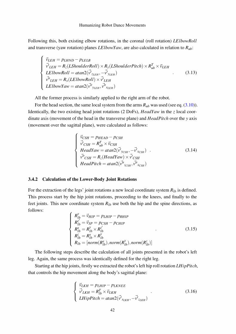
Humanizing Robot Dance Movements
Following this, both existing elbow rotations, in the coronal (roll rotation) LElbowRolland transverse (yaw rotation) planes LElbowYaw, are also calculated in relation to Rub:
~vLEH = pLHND− pLELB~v′LEH = Rz(LShoulderRoll)×Ry(LShoulderPitch)×RT
ub×~vLEH
LElbowRoll = atan2(~v′zLEH ,−~v′yLEH )~v′′LEH = Rx(LElbowRoll)×~v′LEH
LElbowYaw = atan2(~v′′yLEH ,~v′′xLEH )
. (3.13)
All the former process is similarly applied to the right arm of the robot.For the head section, the same local system from the arms Rub was used (see eq. (3.10)).
Identically, the two existing head joint rotations (2 DoFs), HeadYaw in the z local coor-dinate axis (movement of the head in the transverse plane) and HeadPitch over the y axis(movement over the sagittal plane), were calculated as follows:
~vCSH = pHEAD− pCSH~v′CSH = RT
ub×~vCSH
HeadYaw = atan2(~v′yCSH ,−~v′xCSH )~v′′CSH = Rz(HeadYaw)×~v′CSH
HeadPitch = atan2(~v′′zCSH ,~v′′xCSH )
. (3.14)
3.4.2 Calculation of the Lower-Body Joint Rotations
For the extraction of the legs’ joint rotations a new local coordinate system Rlb is defined.This process start by the hip joint rotations, proceeding to the knees, and finally to thefeet joints. This new coordinate system Rlb use both the hip and the spine directions, asfollows:
Rylb =~vHIP = pLHIP− pRHIP
Rz′lb =~vSP = pCSH− pCHIP
Rxlb = Ry
lb×Rz′lb
Rzlb = Rx
lb×Rylb
Rlb = [norm(Rxlb),norm(Ry
lb),norm(Rzlb)]
. (3.15)
The following steps describe the calculation of all joints presented in the robot’s leftleg. Again, the same process was identically defined for the right leg.
Starting at the hip joints, firstly we extracted the robot’s left hip roll rotation LHipPitch,that controls the hip movement along the body’s sagittal plane:
~vLKH = pLHIP− pLKNEE~v′LKH = RT
lb×~vLKH
LHipPitch = atan2(~v′xLKH ,−~v′zLKH )
. (3.16)
42
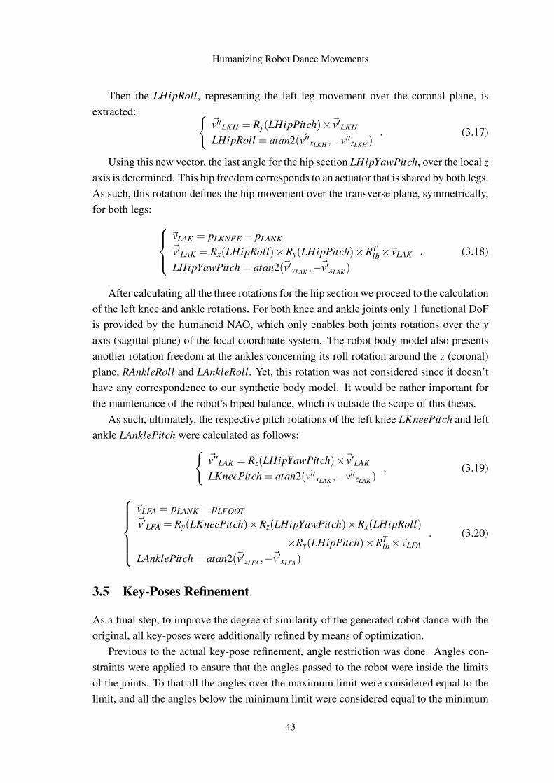
Humanizing Robot Dance Movements
Then the LHipRoll, representing the left leg movement over the coronal plane, isextracted: {
~v′′LKH = Ry(LHipPitch)×~v′LKH
LHipRoll = atan2(~v′′xLKH ,−~v′′zLKH ). (3.17)
Using this new vector, the last angle for the hip section LHipYawPitch, over the local zaxis is determined. This hip freedom corresponds to an actuator that is shared by both legs.As such, this rotation defines the hip movement over the transverse plane, symmetrically,for both legs:
~vLAK = pLKNEE − pLANK~v′LAK = Rx(LHipRoll)×Ry(LHipPitch)×RT
lb×~vLAK
LHipYawPitch = atan2(~v′yLAK ,−~v′xLAK)
. (3.18)
After calculating all the three rotations for the hip section we proceed to the calculationof the left knee and ankle rotations. For both knee and ankle joints only 1 functional DoFis provided by the humanoid NAO, which only enables both joints rotations over the yaxis (sagittal plane) of the local coordinate system. The robot body model also presentsanother rotation freedom at the ankles concerning its roll rotation around the z (coronal)plane, RAnkleRoll and LAnkleRoll. Yet, this rotation was not considered since it doesn’thave any correspondence to our synthetic body model. It would be rather important forthe maintenance of the robot’s biped balance, which is outside the scope of this thesis.
As such, ultimately, the respective pitch rotations of the left knee LKneePitch and leftankle LAnklePitch were calculated as follows:{
~v′′LAK = Rz(LHipYawPitch)×~v′LAK
LKneePitch = atan2(~v′′xLAK ,−~v′′zLAK), (3.19)
~vLFA = pLANK− pLFOOT~v′LFA = Ry(LKneePitch)×Rz(LHipYawPitch)×Rx(LHipRoll)
×Ry(LHipPitch)×RTlb×~vLFA
LAnklePitch = atan2(~v′zLFA ,−~v′xLFA)
. (3.20)
3.5 Key-Poses Refinement
As a final step, to improve the degree of similarity of the generated robot dance with theoriginal, all key-poses were additionally refined by means of optimization.
Previous to the actual key-pose refinement, angle restriction was done. Angles con-straints were applied to ensure that the angles passed to the robot were inside the limitsof the joints. To that all the angles over the maximum limit were considered equal to thelimit, and all the angles below the minimum limit were considered equal to the minimum
43
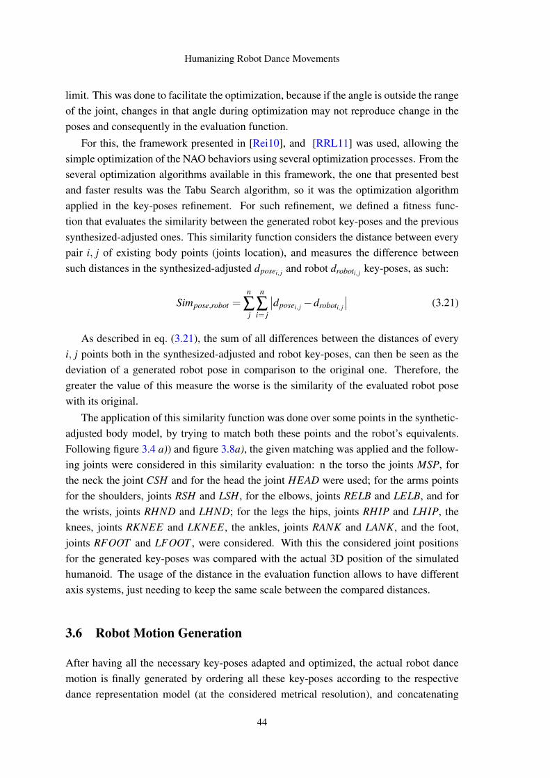
Humanizing Robot Dance Movements
limit. This was done to facilitate the optimization, because if the angle is outside the rangeof the joint, changes in that angle during optimization may not reproduce change in theposes and consequently in the evaluation function.
For this, the framework presented in [Rei10], and [RRL11] was used, allowing thesimple optimization of the NAO behaviors using several optimization processes. From theseveral optimization algorithms available in this framework, the one that presented bestand faster results was the Tabu Search algorithm, so it was the optimization algorithmapplied in the key-poses refinement. For such refinement, we defined a fitness func-tion that evaluates the similarity between the generated robot key-poses and the previoussynthesized-adjusted ones. This similarity function considers the distance between everypair i, j of existing body points (joints location), and measures the difference betweensuch distances in the synthesized-adjusted dposei, j and robot droboti, j key-poses, as such:
Simpose,robot =n
∑j
n
∑i= j
∣∣dposei, j −droboti, j
∣∣ (3.21)
As described in eq. (3.21), the sum of all differences between the distances of everyi, j points both in the synthesized-adjusted and robot key-poses, can then be seen as thedeviation of a generated robot pose in comparison to the original one. Therefore, thegreater the value of this measure the worse is the similarity of the evaluated robot posewith its original.
The application of this similarity function was done over some points in the synthetic-adjusted body model, by trying to match both these points and the robot’s equivalents.Following figure 3.4 a)) and figure 3.8a), the given matching was applied and the follow-ing joints were considered in this similarity evaluation: n the torso the joints MSP, forthe neck the joint CSH and for the head the joint HEAD were used; for the arms pointsfor the shoulders, joints RSH and LSH, for the elbows, joints RELB and LELB, and forthe wrists, joints RHND and LHND; for the legs the hips, joints RHIP and LHIP, theknees, joints RKNEE and LKNEE, the ankles, joints RANK and LANK, and the foot,joints RFOOT and LFOOT , were considered. With this the considered joint positionsfor the generated key-poses was compared with the actual 3D position of the simulatedhumanoid. The usage of the distance in the evaluation function allows to have differentaxis systems, just needing to keep the same scale between the compared distances.
3.6 Robot Motion Generation
After having all the necessary key-poses adapted and optimized, the actual robot dancemotion is finally generated by ordering all these key-poses according to the respectivedance representation model (at the considered metrical resolution), and concatenating
44
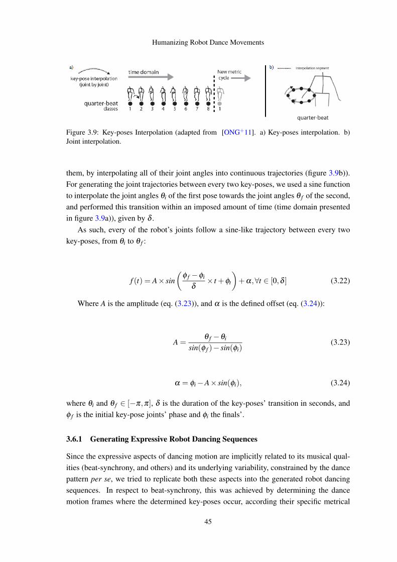
Humanizing Robot Dance Movements
Figure 3.9: Key-poses Interpolation (adapted from [ONG+11]. a) Key-poses interpolation. b)Joint interpolation.
them, by interpolating all of their joint angles into continuous trajectories (figure 3.9b)).For generating the joint trajectories between every two key-poses, we used a sine functionto interpolate the joint angles θi of the first pose towards the joint angles θ f of the second,and performed this transition within an imposed amount of time (time domain presentedin figure 3.9a)), given by δ .
As such, every of the robot’s joints follow a sine-like trajectory between every twokey-poses, from θi to θ f :
f (t) = A× sin(
φ f −φi
δ× t +φt
)+α,∀t ∈ [0,δ ] (3.22)
Where A is the amplitude (eq. (3.23)), and α is the defined offset (eq. (3.24)):
A =θ f −θi
sin(φ f )− sin(φi)(3.23)
α = φi−A× sin(φi), (3.24)
where θi and θ f ∈ [−π,π], δ is the duration of the key-poses’ transition in seconds, andφ f is the initial key-pose joints’ phase and φi the finals’.
3.6.1 Generating Expressive Robot Dancing Sequences
Since the expressive aspects of dancing motion are implicitly related to its musical qual-ities (beat-synchrony, and others) and its underlying variability, constrained by the dancepattern per se, we tried to replicate both these aspects into the generated robot dancingsequences. In respect to beat-synchrony, this was achieved by determining the dancemotion frames where the determined key-poses occur, according their specific metrical
45
Humanizing Robot Dance Movements
classes (given by the former spatiotemporal dance representation), and so calculating foreach pose p its correspondent duration of transition to the next pose p+1:
δp =( f ramep+1− f ramep)
f req, (3.25)
where f req is the frame rate (100 frames per second). This calculation is done to find thecorrect time between the poses, and the time between the key-poses is used as the durationof the transition between two poses.
As the process of synthesizing key-poses uses the random selection of rotations, andthe motion is done by the cyclic repetition of this poses (figure 3.9a)), we will obtainvariability in the final generated dance motion. The final dance sequence is then built byconcatenating successive cycles of key-poses, synthesized with variability at quarter-beatresolution, according to the dance TGA representation.
3.7 Conclusions
In this chapter were presented the methods necessary for analyzing, adapting and gener-ation of the dance motion fundamental key-poses. The methods for generation and sizeadaptation presented are flexible and simple to use, enabling the easy generation of key-poses with the desired body model. Further morphology adaptation was necessary, andthe methods to do so were presented. The extracted and adapted key-poses act as a inter-mediate representation, from which angles were extracted in order to enable the humanoidrobot to reproduce the same key-poses. With this extraction, XML Slot Behaviors werebuilt in SimSpark simulator, and as this extraction may not be exact, refinement of thekey-poses was applied by means of Tabu Search optimization. The optimization of thekey-poses helped enhancing the similarity of the humanoid key-poses to the original ones.After this step, the humanoid dance motion is generated by sine-interpolation, ordered ac-cording to the used dance representation model. Further testing of this methods shouldbe done concerning mainly the similarity of the key-poses and the similarity of the finalhumanoid dance motion with the original human dance. Specifically, it’s also importantto understand the impact that the morphological adaptation has in the dance in terms ofsimilarity. In every case, it must be ensured that all the applied methods don’t produceany unwanted alteration in the body model. Ultimately, the effect of introducing musicalsynchrony and variability in order to generate expressive robot dance performances mustbe also evaluated.
46
Chapter 4
Experiments and Results
This section presents the performed experiments and the respective obtained results. Themethods presented in Chapter 3 were tested in terms of pose similarity with the originalcaptured dance, and overall musical expressiveness of the final generated robot dance.The presented tests and results aim to validate all the proposed methods, by evaluatingand presenting visual insights of the several performed adaptations and motion retargetingtowards the resultant robot dance, while overcoming all the morphological differences andkinematic constraints imposed by the used humanoid body model in comparison to theoriginal human-based captured.
In terms of overall similarity with the original dance, we performed individual testsover the produced key-poses by each stage of the whole process (synthesis, adaptation,retargeting, and refinement), always comparing these with the ones generated by the justprevious stage, and with the original captured ones. This evaluation, done by means ofnumerical measurements or visual comparison, of the generated key-poses at each processstage, allows measuring the individual effect of each method in terms of gains and lossesof similarity in comparison to the original dance, that we aim to replicate.
As a complement, all methods’ results were individually evaluated in terms of mor-phological consistency to check if they were not compromising the fixed geometry of thehumanoid body model, in the process. Again, this is performed by recurring to specificnumerical measurements and visualization of physical details, that aim to confirm the cor-rect disposition of all joints and segment lengths according to the target humanoid bodymodel.
Finally, in order to evaluate the degree of musical expressiveness of the generatedrobot dance, which includes the effect of introducing variability and the degree of beat-synchrony, and given the higher subjectiveness of these aspects, we additionally per-formed an on-line user-evaluation with some video trials followed by proper questions
47
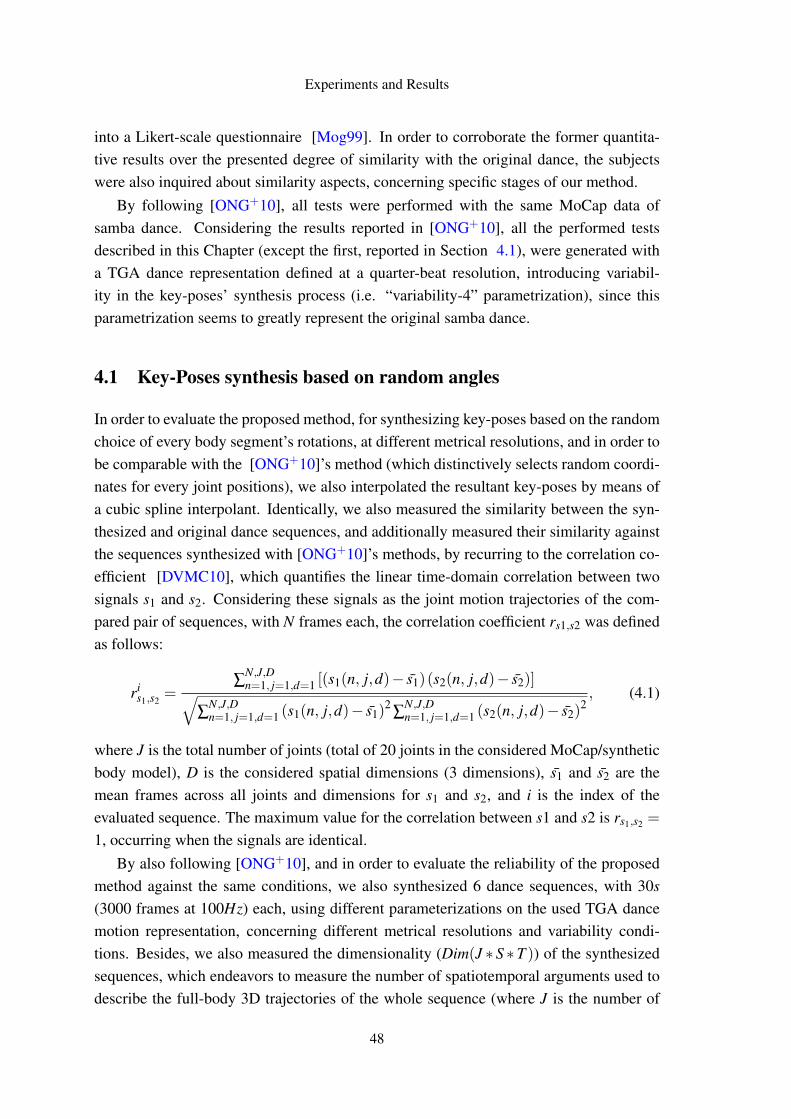
Experiments and Results
into a Likert-scale questionnaire [Mog99]. In order to corroborate the former quantita-tive results over the presented degree of similarity with the original dance, the subjectswere also inquired about similarity aspects, concerning specific stages of our method.
By following [ONG+10], all tests were performed with the same MoCap data ofsamba dance. Considering the results reported in [ONG+10], all the performed testsdescribed in this Chapter (except the first, reported in Section 4.1), were generated witha TGA dance representation defined at a quarter-beat resolution, introducing variabil-ity in the key-poses’ synthesis process (i.e. “variability-4” parametrization), since thisparametrization seems to greatly represent the original samba dance.
4.1 Key-Poses synthesis based on random angles
In order to evaluate the proposed method, for synthesizing key-poses based on the randomchoice of every body segment’s rotations, at different metrical resolutions, and in order tobe comparable with the [ONG+10]’s method (which distinctively selects random coordi-nates for every joint positions), we also interpolated the resultant key-poses by means ofa cubic spline interpolant. Identically, we also measured the similarity between the syn-thesized and original dance sequences, and additionally measured their similarity againstthe sequences synthesized with [ONG+10]’s methods, by recurring to the correlation co-efficient [DVMC10], which quantifies the linear time-domain correlation between twosignals s1 and s2. Considering these signals as the joint motion trajectories of the com-pared pair of sequences, with N frames each, the correlation coefficient rs1,s2 was definedas follows:
ris1,s2
=∑
N,J,Dn=1, j=1,d=1 [(s1(n, j,d)− s̄1)(s2(n, j,d)− s̄2)]√
∑N,J,Dn=1, j=1,d=1 (s1(n, j,d)− s̄1)
2∑
N,J,Dn=1, j=1,d=1 (s2(n, j,d)− s̄2)
2, (4.1)
where J is the total number of joints (total of 20 joints in the considered MoCap/syntheticbody model), D is the considered spatial dimensions (3 dimensions), s̄1 and s̄2 are themean frames across all joints and dimensions for s1 and s2, and i is the index of theevaluated sequence. The maximum value for the correlation between s1 and s2 is rs1,s2 =
1, occurring when the signals are identical.By also following [ONG+10], and in order to evaluate the reliability of the proposed
method against the same conditions, we also synthesized 6 dance sequences, with 30s(3000 frames at 100Hz) each, using different parameterizations on the used TGA dancemotion representation, concerning different metrical resolutions and variability condi-tions. Besides, we also measured the dimensionality (Dim(J ∗ S ∗T )) of the synthesizedsequences, which endeavors to measure the number of spatiotemporal arguments used todescribe the full-body 3D trajectories of the whole sequence (where J is the number of
48
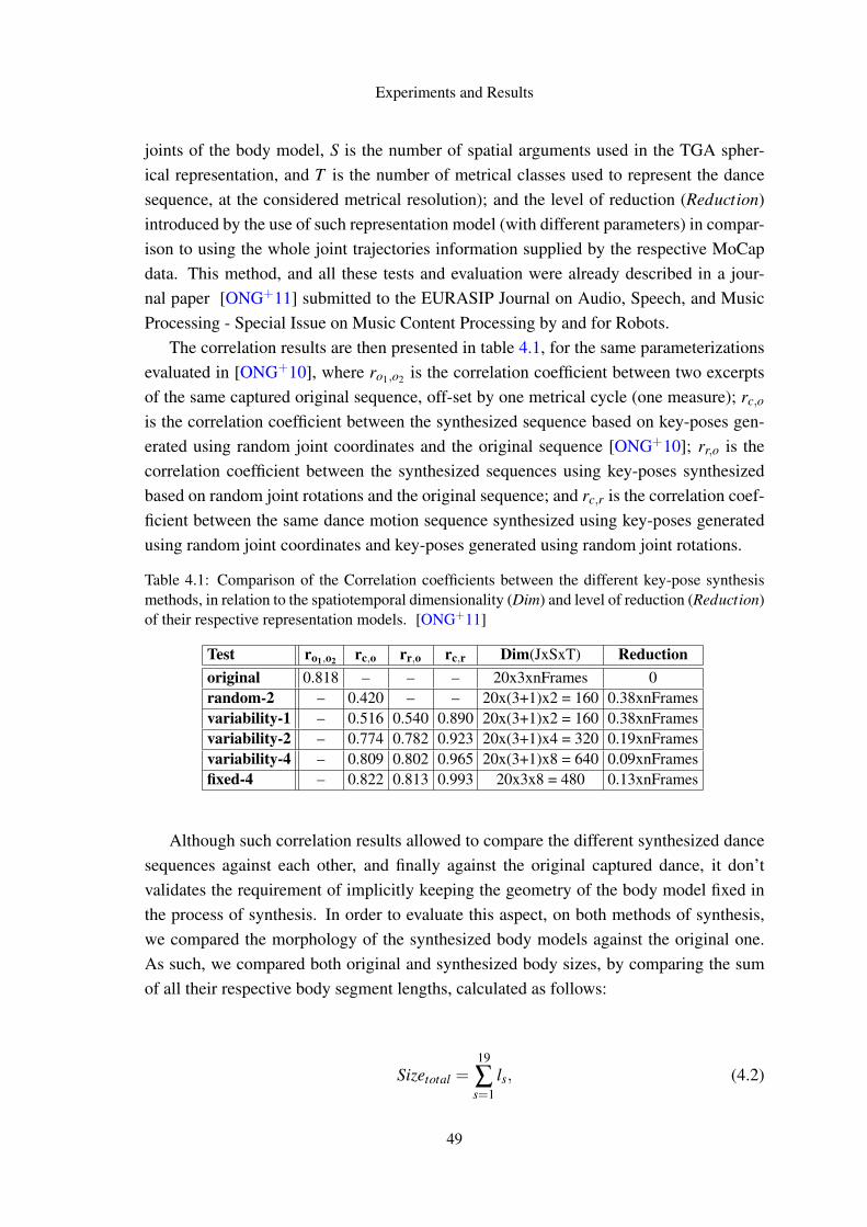
Experiments and Results
joints of the body model, S is the number of spatial arguments used in the TGA spher-ical representation, and T is the number of metrical classes used to represent the dancesequence, at the considered metrical resolution); and the level of reduction (Reduction)introduced by the use of such representation model (with different parameters) in compar-ison to using the whole joint trajectories information supplied by the respective MoCapdata. This method, and all these tests and evaluation were already described in a jour-nal paper [ONG+11] submitted to the EURASIP Journal on Audio, Speech, and MusicProcessing - Special Issue on Music Content Processing by and for Robots.
The correlation results are then presented in table 4.1, for the same parameterizationsevaluated in [ONG+10], where ro1,o2 is the correlation coefficient between two excerptsof the same captured original sequence, off-set by one metrical cycle (one measure); rc,o
is the correlation coefficient between the synthesized sequence based on key-poses gen-erated using random joint coordinates and the original sequence [ONG+10]; rr,o is thecorrelation coefficient between the synthesized sequences using key-poses synthesizedbased on random joint rotations and the original sequence; and rc,r is the correlation coef-ficient between the same dance motion sequence synthesized using key-poses generatedusing random joint coordinates and key-poses generated using random joint rotations.
Table 4.1: Comparison of the Correlation coefficients between the different key-pose synthesismethods, in relation to the spatiotemporal dimensionality (Dim) and level of reduction (Reduction)of their respective representation models. [ONG+11]
Test ro1,o2 rc,o rr,o rc,r Dim(JxSxT) Reductionoriginal 0.818 – – – 20x3xnFrames 0random-2 – 0.420 – – 20x(3+1)x2 = 160 0.38xnFramesvariability-1 – 0.516 0.540 0.890 20x(3+1)x2 = 160 0.38xnFramesvariability-2 – 0.774 0.782 0.923 20x(3+1)x4 = 320 0.19xnFramesvariability-4 – 0.809 0.802 0.965 20x(3+1)x8 = 640 0.09xnFramesfixed-4 – 0.822 0.813 0.993 20x3x8 = 480 0.13xnFrames
Although such correlation results allowed to compare the different synthesized dancesequences against each other, and finally against the original captured dance, it don’tvalidates the requirement of implicitly keeping the geometry of the body model fixed inthe process of synthesis. In order to evaluate this aspect, on both methods of synthesis,we compared the morphology of the synthesized body models against the original one.As such, we compared both original and synthesized body sizes, by comparing the sumof all their respective body segment lengths, calculated as follows:
Sizetotal =19
∑s=1
ls, (4.2)
49
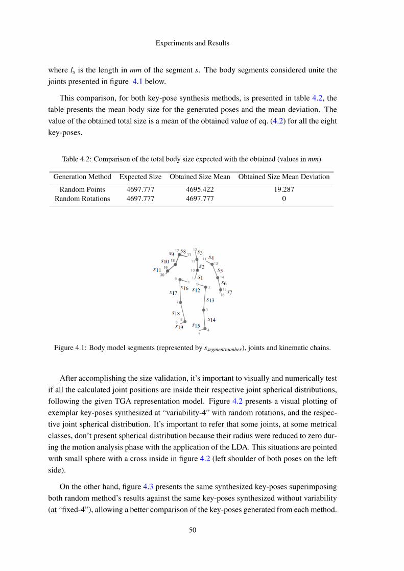
Experiments and Results
where ls is the length in mm of the segment s. The body segments considered unite thejoints presented in figure 4.1 below.
This comparison, for both key-pose synthesis methods, is presented in table 4.2, thetable presents the mean body size for the generated poses and the mean deviation. Thevalue of the obtained total size is a mean of the obtained value of eq. (4.2) for all the eightkey-poses.
Table 4.2: Comparison of the total body size expected with the obtained (values in mm).
Generation Method Expected Size Obtained Size Mean Obtained Size Mean Deviation
Random Points 4697.777 4695.422 19.287Random Rotations 4697.777 4697.777 0
Figure 4.1: Body model segments (represented by ssegmentnumber), joints and kinematic chains.
After accomplishing the size validation, it’s important to visually and numerically testif all the calculated joint positions are inside their respective joint spherical distributions,following the given TGA representation model. Figure 4.2 presents a visual plotting ofexemplar key-poses synthesized at “variability-4” with random rotations, and the respec-tive joint spherical distribution. It’s important to refer that some joints, at some metricalclasses, don’t present spherical distribution because their radius were reduced to zero dur-ing the motion analysis phase with the application of the LDA. This situations are pointedwith small sphere with a cross inside in figure 4.2 (left shoulder of both poses on the leftside).
On the other hand, figure 4.3 presents the same synthesized key-poses superimposingboth random method’s results against the same key-poses synthesized without variability(at “fixed-4”), allowing a better comparison of the key-poses generated from each method.
50
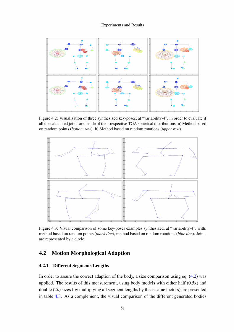
Experiments and Results
−250 −200 −150 −100 −50 0 50 100 150900
1000
1100
1200
1300
1400
1500
−150 −100 −50 0 50 100 150 200900
1000
1100
1200
1300
1400
1500
−200 −150 −100 −50 0 50 100 150 200900
1000
1100
1200
1300
1400
1500
−250 −200 −150 −100 −50 0 50 100 150900
1000
1100
1200
1300
1400
1500
−150 −100 −50 0 50 100 150 200900
1000
1100
1200
1300
1400
1500
−200 −150 −100 −50 0 50 100 150 200900
1000
1100
1200
1300
1400
1500
Figure 4.2: Visualization of three synthesized key-poses, at “variability-4”, in order to evaluate ifall the calculated joints are inside of their respective TGA spherical distributions. a) Method basedon random points (bottom row). b) Method based on random rotations (upper row).
−500 −400 −300 −200 −100 0 100 200 300 400200
400
600
800
1000
1200
1400
1600
1800
2000
−300 −200 −100 0 100 200 300200
400
600
800
1000
1200
1400
1600
1800
2000
−300 −200 −100 0 100 200 300 400200
400
600
800
1000
1200
1400
1600
1800
2000
−400 −300 −200 −100 0 100 200 300200
400
600
800
1000
1200
1400
1600
1800
2000
Figure 4.3: Visual comparison of some key-poses examples synthesized, at “variability-4”, with:method based on random points (black line), method based on random rotations (blue line). Jointsare represented by a circle.
4.2 Motion Morphological Adaption
4.2.1 Different Segments Lengths
In order to assure the correct adaption of the body, a size comparison using eq. (4.2) wasapplied. The results of this measurement, using body models with either half (0.5x) anddouble (2x) sizes (by multiplying all segment lengths by these same factors) are presentedin table 4.3. As a complement, the visual comparison of the different generated bodies
51
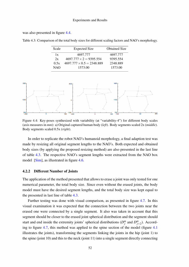
Experiments and Results
was also presented in figure 4.4.
Table 4.3: Comparison of the total body sizes for different scaling factors and NAO’s morphology.
Scale Expected Size Obtained Size
1x 4697.777 4697.7772x 4697.777×2 = 9395.554 9395.554
0.5x 4697.777×0.5 = 2348.889 2348.889NAO 1573.00 1573.00
Figure 4.4: Key-poses synthesized with variability (at “variability-4”) for different body scales(axis measures in mm): a) Original captured human body (left). Body segments scaled 2x (middle).Body segments scaled 0.5x (right).
In order to replicate the robot NAO’s humanoid morphology, a final adaption test wasmade by resizing all original segment lengths to the NAO’s. Both expected and obtainedbody sizes (by applying the proposed resizing method) are also presented in the last lineof table 4.3. The respective NAO’s segment lengths were extracted from the NAO boxmodel [Sim], as illustrated in figure 4.6.
4.2.2 Different Number of Joints
The application of the method presented that allows to erase a joint was only tested for onenumerical parameter, the total body size. Since even without the erased joints, the bodymodel must have the desired segment lengths, and the total body size was kept equal tothe presented in last line of table 4.3.
Further testing was done with visual comparison, as presented in figure 4.7. In thisvisual examination it was expected that the connection between the two joints near theerased one were connected by a single segment. It also was taken in account that thissegment should be closer to the erased joint spherical distribution and the segment shouldstart and end inside the extremity joints’ spherical distributions (Dm
j and Dmj+2). Accord-
ing to figure 4.7, this method was applied to the spine section of the model (figure 4.1illustrates the joints), transforming the segments linking the joints in the hip (joint 1) tothe spine (joint 10) and this to the neck (joint 11) into a single segment directly connecting
52
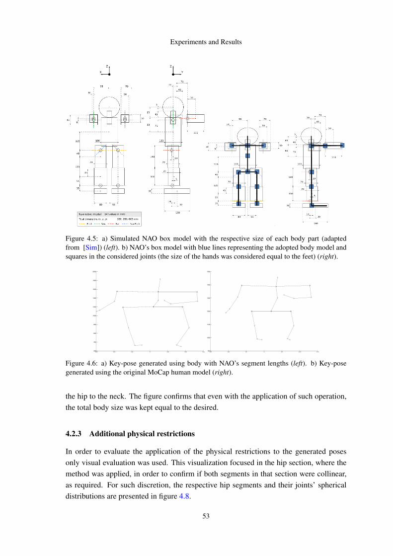
Experiments and Results
Figure 4.5: a) Simulated NAO box model with the respective size of each body part (adaptedfrom [Sim]) (left). b) NAO’s box model with blue lines representing the adopted body model andsquares in the considered joints (the size of the hands was considered equal to the feet) (right).
−300 −200 −100 0 100 200 300200
400
600
800
1000
1200
1400
1600
1800
2000
−150 −100 −50 0 50 100 150900
1000
1100
1200
1300
1400
1500
Figure 4.6: a) Key-pose generated using body with NAO’s segment lengths (left). b) Key-posegenerated using the original MoCap human model (right).
the hip to the neck. The figure confirms that even with the application of such operation,the total body size was kept equal to the desired.
4.2.3 Additional physical restrictions
In order to evaluate the application of the physical restrictions to the generated posesonly visual evaluation was used. This visualization focused in the hip section, where themethod was applied, in order to confirm if both segments in that section were collinear,as required. For such discretion, the respective hip segments and their joints’ sphericaldistributions are presented in figure 4.8.
53
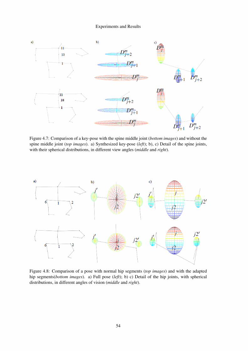
Experiments and Results
Figure 4.7: Comparison of a key-pose with the spine middle joint (bottom images) and without thespine middle joint (top images). a) Synthesized key-pose (left); b), c) Detail of the spine joints,with their spherical distributions, in different view angles (middle and right).
Figure 4.8: Comparison of a pose with normal hip segments (top images) and with the adaptedhip segments(bottom images). a) Full pose (left); b) c) Detail of the hip joints, with sphericaldistributions, in different angles of vision (middle and right).
54
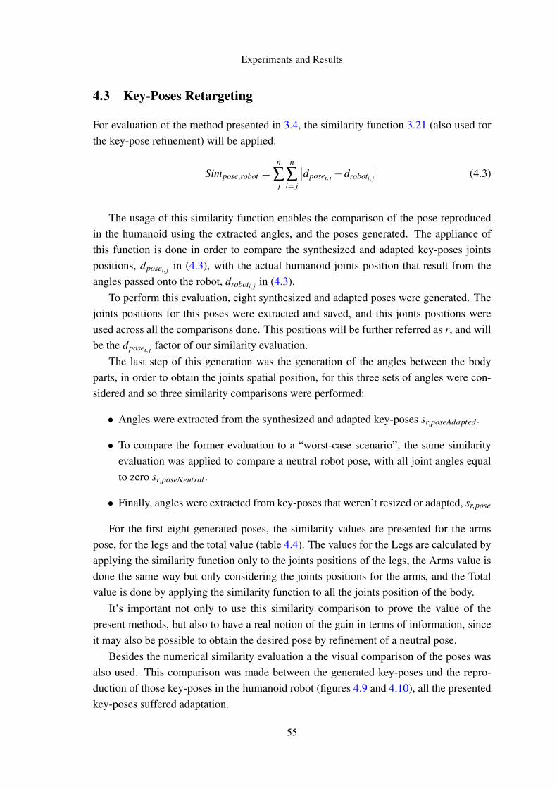
Experiments and Results
4.3 Key-Poses Retargeting
For evaluation of the method presented in 3.4, the similarity function 3.21 (also used forthe key-pose refinement) will be applied:
Simpose,robot =n
∑j
n
∑i= j
∣∣dposei, j −droboti, j
∣∣ (4.3)
The usage of this similarity function enables the comparison of the pose reproducedin the humanoid using the extracted angles, and the poses generated. The appliance ofthis function is done in order to compare the synthesized and adapted key-poses jointspositions, dposei, j in (4.3), with the actual humanoid joints position that result from theangles passed onto the robot, droboti, j in (4.3).
To perform this evaluation, eight synthesized and adapted poses were generated. Thejoints positions for this poses were extracted and saved, and this joints positions wereused across all the comparisons done. This positions will be further referred as r, and willbe the dposei, j factor of our similarity evaluation.
The last step of this generation was the generation of the angles between the bodyparts, in order to obtain the joints spatial position, for this three sets of angles were con-sidered and so three similarity comparisons were performed:
• Angles were extracted from the synthesized and adapted key-poses sr,poseAdapted .
• To compare the former evaluation to a “worst-case scenario”, the same similarityevaluation was applied to compare a neutral robot pose, with all joint angles equalto zero sr,poseNeutral .
• Finally, angles were extracted from key-poses that weren’t resized or adapted, sr,pose
For the first eight generated poses, the similarity values are presented for the armspose, for the legs and the total value (table 4.4). The values for the Legs are calculated byapplying the similarity function only to the joints positions of the legs, the Arms value isdone the same way but only considering the joints positions for the arms, and the Totalvalue is done by applying the similarity function to all the joints position of the body.
It’s important not only to use this similarity comparison to prove the value of thepresent methods, but also to have a real notion of the gain in terms of information, sinceit may also be possible to obtain the desired pose by refinement of a neutral pose.
Besides the numerical similarity evaluation a the visual comparison of the poses wasalso used. This comparison was made between the generated key-poses and the repro-duction of those key-poses in the humanoid robot (figures 4.9 and 4.10), all the presentedkey-poses suffered adaptation.
55
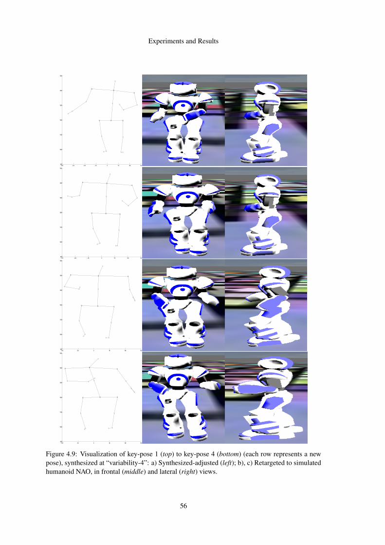
Experiments and Results
−200 −150 −100 −50 0 50 100 150900
1000
1100
1200
1300
1400
1500
−150 −100 −50 0 50 100 150900
1000
1100
1200
1300
1400
1500
−100 −50 0 50 100 150900
1000
1100
1200
1300
1400
1500
−100 −50 0 50 100 150900
1000
1100
1200
1300
1400
1500
Figure 4.9: Visualization of key-pose 1 (top) to key-pose 4 (bottom) (each row represents a newpose), synthesized at “variability-4”: a) Synthesized-adjusted (left); b), c) Retargeted to simulatedhumanoid NAO, in frontal (middle) and lateral (right) views.
56
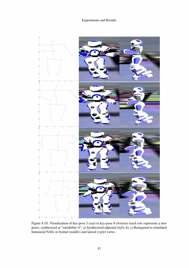
Experiments and Results
−100 −50 0 50 100 150 200900
1000
1100
1200
1300
1400
1500
−100 −50 0 50 100 150900
1000
1100
1200
1300
1400
1500
−100 −50 0 50 100 150900
1000
1100
1200
1300
1400
1500
−150 −100 −50 0 50 100 150900
1000
1100
1200
1300
1400
1500
Figure 4.10: Visualization of key-pose 5 (top) to key-pose 8 (bottom) (each row represents a newpose), synthesized at “variability-4”: a) Synthesized-adjusted (left); b), c) Retargeted to simulatedhumanoid NAO, in frontal (middle) and lateral (right) views.
57
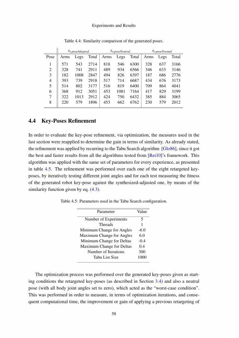
Experiments and Results
Table 4.4: Similarity comparison of the generated poses.
sr,poseAdapted sr,poseNeutral sr,poseNormal
Pose Arms Legs Total Arms Legs Total Arms Legs Total
1 571 543 2714 818 546 6300 328 637 31662 328 741 2911 489 934 6566 346 633 31463 182 1008 2847 494 826 6397 187 686 27764 393 739 2918 517 714 6687 434 676 31735 514 802 3177 516 819 6400 709 864 40416 368 912 3051 453 1081 7164 417 829 31997 322 1013 2912 424 750 6432 385 884 30658 220 579 1896 453 662 6762 230 579 2012
4.4 Key-Poses Refinement
In order to evaluate the key-pose refinement, via optimization, the measures used in thelast section were reapplied to determine the gain in terms of similarity. As already stated,the refinement was applied by recurring to the Tabu Search algorithm [Glo86], since it gotthe best and faster results from all the algorithms tested from [Rei10]’s framework. Thisalgorithm was applied with the same set of parameters for every experience, as presentedin table 4.5. The refinement was performed over each one of the eight retargeted key-poses, by iteratively testing different joint angles and for each test measuring the fitnessof the generated robot key-pose against the synthesized-adjusted one, by means of thesimilarity function given by eq. (4.3).
Table 4.5: Parameters used in the Tabu Search configuration.
Parameter Value
Number of Experiments 5Threads 1
Minimum Change for Angles -6.0Maximum Change for Angles 6.0Minimum Change for Deltas -0.4Maximum Change for Deltas 0.4
Number of Iterations 300Tabu List Size 1000
The optimization process was performed over the generated key-poses given as start-ing conditions the retargeted key-poses (as described in Section 3.4) and also a neutralpose (with all body joint angles set to zero), which acted as the “worst-case condition”.This was performed in order to measure, in terms of optimization iterations, and conse-quent computational time, the improvement or gain of applying a previous retargeting of
58
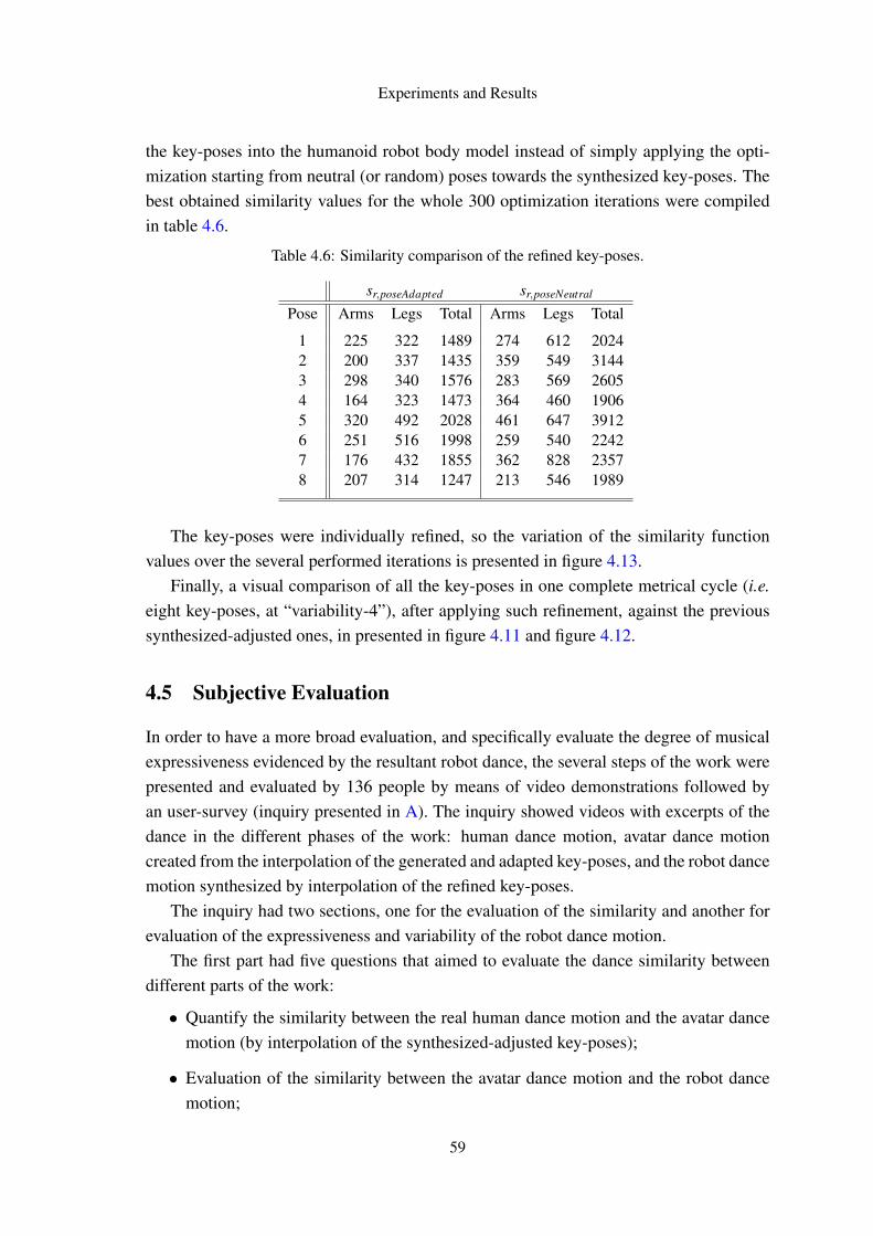
Experiments and Results
the key-poses into the humanoid robot body model instead of simply applying the opti-mization starting from neutral (or random) poses towards the synthesized key-poses. Thebest obtained similarity values for the whole 300 optimization iterations were compiledin table 4.6.
Table 4.6: Similarity comparison of the refined key-poses.
sr,poseAdapted sr,poseNeutral
Pose Arms Legs Total Arms Legs Total
1 225 322 1489 274 612 20242 200 337 1435 359 549 31443 298 340 1576 283 569 26054 164 323 1473 364 460 19065 320 492 2028 461 647 39126 251 516 1998 259 540 22427 176 432 1855 362 828 23578 207 314 1247 213 546 1989
The key-poses were individually refined, so the variation of the similarity functionvalues over the several performed iterations is presented in figure 4.13.
Finally, a visual comparison of all the key-poses in one complete metrical cycle (i.e.eight key-poses, at “variability-4”), after applying such refinement, against the previoussynthesized-adjusted ones, in presented in figure 4.11 and figure 4.12.
4.5 Subjective Evaluation
In order to have a more broad evaluation, and specifically evaluate the degree of musicalexpressiveness evidenced by the resultant robot dance, the several steps of the work werepresented and evaluated by 136 people by means of video demonstrations followed byan user-survey (inquiry presented in A). The inquiry showed videos with excerpts of thedance in the different phases of the work: human dance motion, avatar dance motioncreated from the interpolation of the generated and adapted key-poses, and the robot dancemotion synthesized by interpolation of the refined key-poses.
The inquiry had two sections, one for the evaluation of the similarity and another forevaluation of the expressiveness and variability of the robot dance motion.
The first part had five questions that aimed to evaluate the dance similarity betweendifferent parts of the work:
• Quantify the similarity between the real human dance motion and the avatar dancemotion (by interpolation of the synthesized-adjusted key-poses);
• Evaluation of the similarity between the avatar dance motion and the robot dancemotion;
59
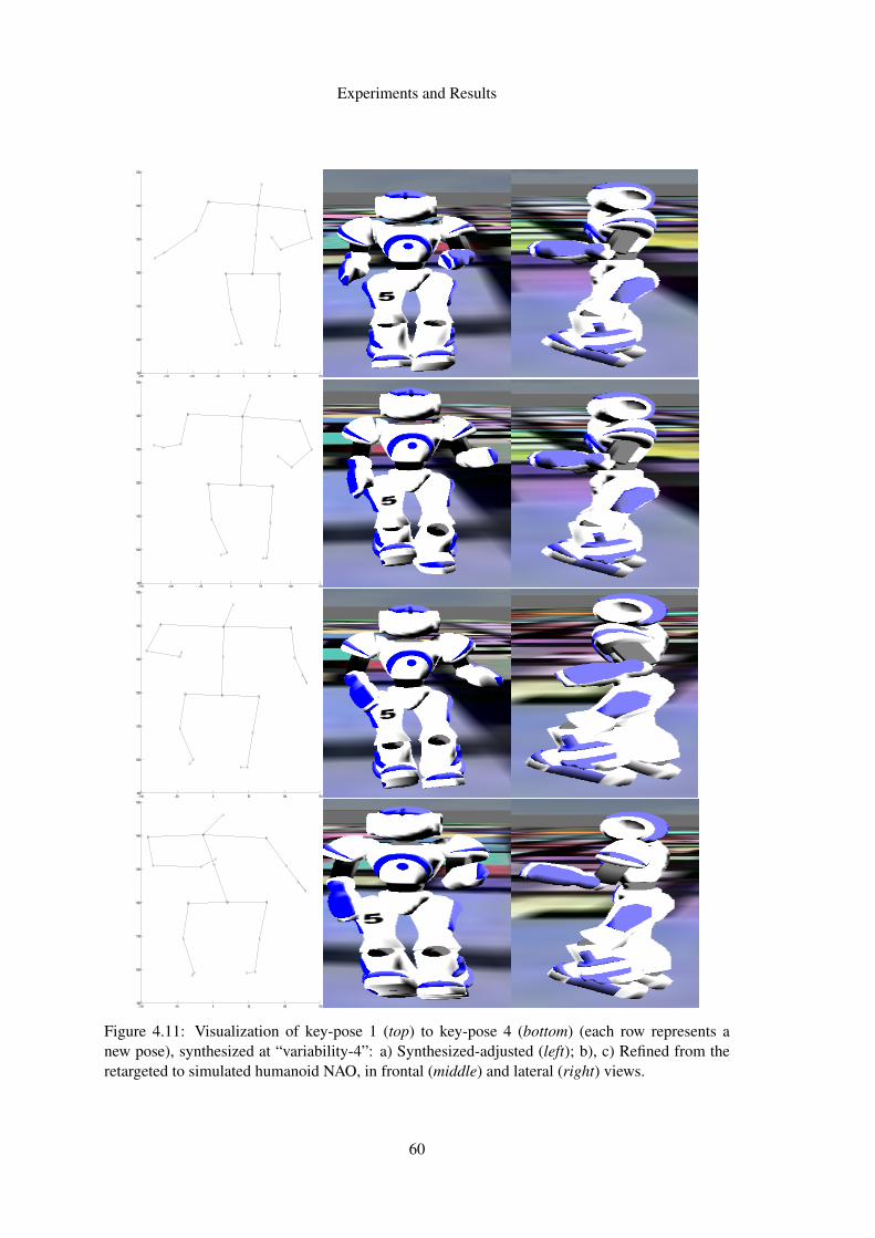
Experiments and Results
−200 −150 −100 −50 0 50 100 150900
1000
1100
1200
1300
1400
1500
−150 −100 −50 0 50 100 150900
1000
1100
1200
1300
1400
1500
−100 −50 0 50 100 150900
1000
1100
1200
1300
1400
1500
−100 −50 0 50 100 150900
1000
1100
1200
1300
1400
1500
Figure 4.11: Visualization of key-pose 1 (top) to key-pose 4 (bottom) (each row represents anew pose), synthesized at “variability-4”: a) Synthesized-adjusted (left); b), c) Refined from theretargeted to simulated humanoid NAO, in frontal (middle) and lateral (right) views.
60
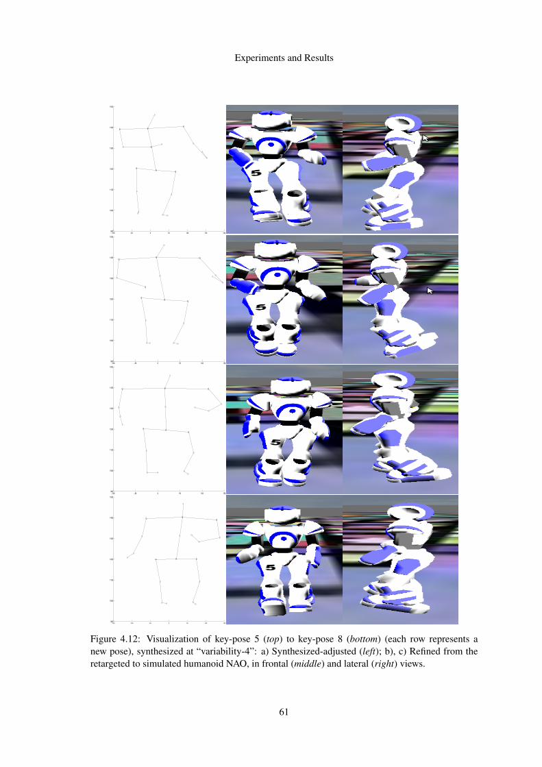
Experiments and Results
−100 −50 0 50 100 150 200900
1000
1100
1200
1300
1400
1500
−100 −50 0 50 100 150900
1000
1100
1200
1300
1400
1500
−100 −50 0 50 100 150900
1000
1100
1200
1300
1400
1500
−150 −100 −50 0 50 100 150900
1000
1100
1200
1300
1400
1500
Figure 4.12: Visualization of key-pose 5 (top) to key-pose 8 (bottom) (each row represents anew pose), synthesized at “variability-4”: a) Synthesized-adjusted (left); b), c) Refined from theretargeted to simulated humanoid NAO, in frontal (middle) and lateral (right) views.
61
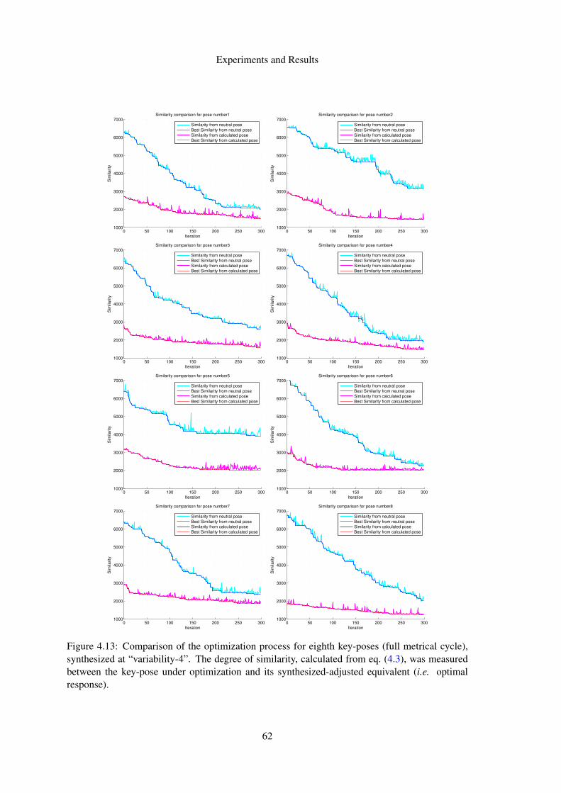
Experiments and Results
0 50 100 150 200 250 3001000
2000
3000
4000
5000
6000
7000
Iteration
Sim
ilarity
Similarity comparison for pose number1
Similarity from neutral pose
Best Similarity from neutral pose
Similarity from calculated pose
Best Similarity from calculated pose
0 50 100 150 200 250 3001000
2000
3000
4000
5000
6000
7000
Iteration
Sim
ilarity
Similarity comparison for pose number2
Similarity from neutral pose
Best Similarity from neutral pose
Similarity from calculated pose
Best Similarity from calculated pose
0 50 100 150 200 250 3001000
2000
3000
4000
5000
6000
7000
Iteration
Sim
ilarity
Similarity comparison for pose number3
Similarity from neutral pose
Best Similarity from neutral pose
Similarity from calculated pose
Best Similarity from calculated pose
0 50 100 150 200 250 3001000
2000
3000
4000
5000
6000
7000
Iteration
Sim
ilarity
Similarity comparison for pose number4
Similarity from neutral pose
Best Similarity from neutral pose
Similarity from calculated pose
Best Similarity from calculated pose
0 50 100 150 200 250 3001000
2000
3000
4000
5000
6000
7000
Iteration
Sim
ilarity
Similarity comparison for pose number5
Similarity from neutral pose
Best Similarity from neutral pose
Similarity from calculated pose
Best Similarity from calculated pose
0 50 100 150 200 250 3001000
2000
3000
4000
5000
6000
7000
Iteration
Sim
ilarity
Similarity comparison for pose number6
Similarity from neutral pose
Best Similarity from neutral pose
Similarity from calculated pose
Best Similarity from calculated pose
0 50 100 150 200 250 3001000
2000
3000
4000
5000
6000
7000
Iteration
Sim
ilarity
Similarity comparison for pose number7
Similarity from neutral pose
Best Similarity from neutral pose
Similarity from calculated pose
Best Similarity from calculated pose
0 50 100 150 200 250 3001000
2000
3000
4000
5000
6000
7000
Iteration
Sim
ilarity
Similarity comparison for pose number8
Similarity from neutral pose
Best Similarity from neutral pose
Similarity from calculated pose
Best Similarity from calculated pose
Figure 4.13: Comparison of the optimization process for eighth key-poses (full metrical cycle),synthesized at “variability-4”. The degree of similarity, calculated from eq. (4.3), was measuredbetween the key-pose under optimization and its synthesized-adjusted equivalent (i.e. optimalresponse).
62
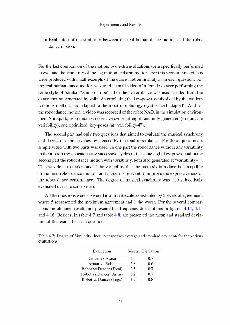
Experiments and Results
• Evaluation of the similarity between the real human dance motion and the robotdance motion.
For the last comparison of the motion, two extra evaluations were specifically performedto evaluate the similarity of the leg motion and arm motion. For this section three videoswere produced with small excerpts of the dance motion in analysis in each question. Forthe real human dance motion was used a small video of a female dancer performing thesame style of Samba (“Samba-no-pé”). For the avatar dance was used a video from thedance motion generated by spline-interpolating the key-poses synthesized by the randomrotations method, and adapted to the robot morphology (synthesized-adapted). And forthe robot dance motion, a video was recorded of the robot NAO, in the simulation environ-ment SimSpark, reproducing successive cycles of eight randomly generated (to translatevariability), and optimized, key-poses (at “variability-4”).
The second part had only two questions that aimed to evaluate the musical synchronyand degree of expressiveness evidenced by the final robot dance. For these questions, asimple video with two parts was used: in one part the robot dance without any variabilityin the motion (by concatenating successive cycles of the same eight key-poses) and in thesecond part the robot dance motion with variability, both also generated at “variability-4”.This was done to understand if the variability that the methods introduce is perceptiblein the final robot dance motion, and if such is relevant to improve the expressiveness ofthe robot dance performance. The degree of musical synchrony was also subjectivelyevaluated over the same video.
All the questions were answered in a Likert-scale, constituted by 5 levels of agreement,where 5 represented the maximum agreement and 1 the worst. For the several compar-isons the obtained results are presented as frequency distributions in figures 4.14, 4.15and 4.16. Besides, in table 4.7 and table 4.8, are presented the mean and standard devia-tion of the results for each question.
Table 4.7: Degree of Similarity. Inquiry responses average and standard deviation for the variousevaluations
Evaluation Mean Deviation
Dancer vs Avatar 3.3 0.7Avatar vs Robot 2.8 0.6
Robot vs Dancer (Total) 2.5 0.7Robot vs Dancer (Arms) 3.2 0.7Robot vs Dancer (Legs) 2.2 0.8
63
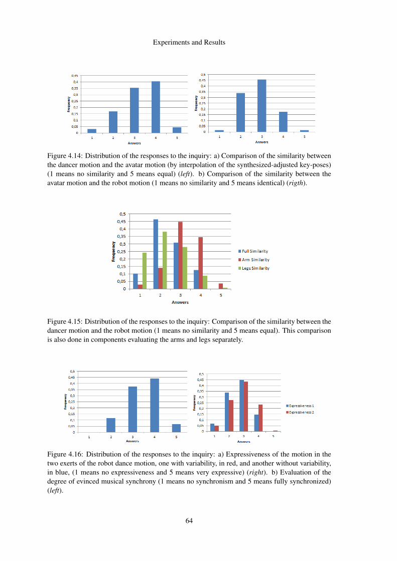
Experiments and Results
Figure 4.14: Distribution of the responses to the inquiry: a) Comparison of the similarity betweenthe dancer motion and the avatar motion (by interpolation of the synthesized-adjusted key-poses)(1 means no similarity and 5 means equal) (left). b) Comparison of the similarity between theavatar motion and the robot motion (1 means no similarity and 5 means identical) (rigth).
Figure 4.15: Distribution of the responses to the inquiry: Comparison of the similarity between thedancer motion and the robot motion (1 means no similarity and 5 means equal). This comparisonis also done in components evaluating the arms and legs separately.
Figure 4.16: Distribution of the responses to the inquiry: a) Expressiveness of the motion in thetwo exerts of the robot dance motion, one with variability, in red, and another without variability,in blue, (1 means no expressiveness and 5 means very expressive) (right). b) Evaluation of thedegree of evinced musical synchrony (1 means no synchronism and 5 means fully synchronized)(left).
64
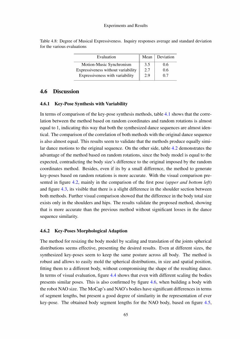
Experiments and Results
Table 4.8: Degree of Musical Expressiveness. Inquiry responses average and standard deviationfor the various evaluations
Evaluation Mean Deviation
Motion-Music Synchronism 3.5 0.6Expressiveness without variability 2.7 0.6
Expressiveness with variability 2.9 0.7
4.6 Discussion
4.6.1 Key-Pose Synthesis with Variability
In terms of comparison of the key-pose synthesis methods, table 4.1 shows that the corre-lation between the method based on random coordinates and random rotations is almostequal to 1, indicating this way that both the synthesized dance sequences are almost iden-tical. The comparison of the correlation of both methods with the original dance sequenceis also almost equal. This results seem to validate that the methods produce equally simi-lar dance motions to the original sequence. On the other side, table 4.2 demonstrates theadvantage of the method based on random rotations, since the body model is equal to theexpected, contradicting the body size’s difference to the original imposed by the randomcoordinates method. Besides, even if its by a small difference, the method to generatekey-poses based on random rotations is more accurate. With the visual comparison pre-sented in figure 4.2, mainly in the comparison of the first pose (upper and bottom left)and figure 4.3, its visible that there is a slight difference in the shoulder section betweenboth methods. Further visual comparison showed that the difference in the body total sizeexists only in the shoulders and hips. The results validate the proposed method, showingthat is more accurate than the previous method without significant losses in the dancesequence similarity.
4.6.2 Key-Poses Morphological Adaption
The method for resizing the body model by scaling and translation of the joints sphericaldistributions seems effective, presenting the desired results. Even at different sizes, thesynthesized key-poses seem to keep the same posture across all body. The method isrobust and allows to easily mold the spherical distributions, in size and spatial position,fitting them to a different body, without compromising the shape of the resulting dance.In terms of visual evaluation, figure 4.4 shows that even with different scaling the bodiespresents similar poses. This is also confirmed by figure 4.6, when building a body withthe robot NAO size. The MoCap’s and NAO’s bodies have significant differences in termsof segment lengths, but present a good degree of similarity in the representation of everkey-pose. The obtained body segment lengths for the NAO body, based on figure 4.5,
65
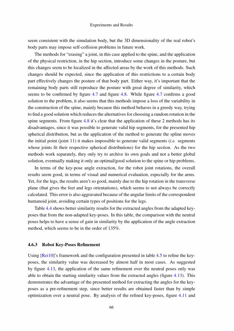
Experiments and Results
seem consistent with the simulation body, but the 3D dimensionality of the real robot’sbody parts may impose self-collision problems in future work.
The methods for “erasing” a joint, in this case applied to the spine, and the applicationof the physical restriction, in the hip section, introduce some changes in the posture, butthis changes seem to be localized in the affected areas by the work of this methods. Suchchanges should be expected, since the application of this restrictions to a certain bodypart effectively changes the posture of that body part. Either way, it’s important that theremaining body parts still reproduce the posture with great degree of similarity, whichseems to be confirmed by figure 4.7 and figure 4.8. While figure 4.7 confirms a goodsolution to the problem, it also seems that this methods impose a loss of the variability inthe construction of the spine, mainly because this method behaves in a greedy way, tryingto find a good solution which reduces the alternatives for choosing a random rotation in thespine segments. From figure 4.8 it’s clear that the application of these 2 methods has itsdisadvantages, since it was possible to generate valid hip segments, for the presented hipspherical distribution, but as the application of the method to generate the spline movesthe initial point (joint 11) it makes impossible to generate valid segments (i.e. segmentswhose joints fit their respective spherical distributions) for the hip section. As the twomethods work separately, they only try to archive its own goals and not a better globalsolution, eventually making it only an optimal/good solution to the spine or hip problems.
In terms of the key-pose angle extraction, for the robot joint rotations, the overallresults seem good, in terms of visual and numerical evaluation, especially for the arms.Yet, for the legs, the results aren’t so good, mainly due to the hip rotation in the transverseplane (that gives the feet and legs orientations), which seems to not always be correctlycalculated. This error is also aggravated because of the angular limits of the correspondenthumanoid joint, avoiding certain types of positions for the legs.
Table 4.4 shows better similarity results for the extracted angles from the adapted key-poses that from the non-adapted key-poses. In this table, the comparison with the neutralposes helps to have a sense of gain in similarity by the application of the angle extractionmethod, which seems to be in the order of 135%.
4.6.3 Robot Key-Poses Refinement
Using [Rei10]’s framework and the configuration presented in table 4.5 to refine the key-poses, the similarity value was decreased by almost half in most cases. As suggestedby figure 4.13, the application of the same refinement over the neutral poses only wasable to obtain the starting similarity values from the extracted angles (figure 4.13). Thisdemonstrates the advantage of the presented method for extracting the angles for the key-poses as a pre-refinement step, since better results are obtained faster than by simpleoptimization over a neutral pose. By analysis of the refined key-poses, figure 4.11 and
66
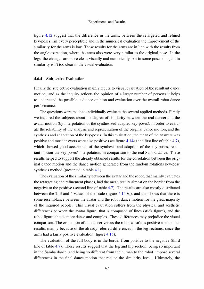
Experiments and Results
figure 4.12 suggest that the difference in the arms, between the retargeted and refinedkey-poses, isn’t very perceptible and in the numerical evaluation the improvement of thesimilarity for the arms is low. These results for the arms are in line with the results fromthe angle extraction, where the arms also were very similar to the original pose. In thelegs, the changes are more clear, visually and numerically, but in some poses the gain insimilarity isn’t too clear in the visual evaluation.
4.6.4 Subjective Evaluation
Finally the subjective evaluation mainly recurs to visual evaluation of the resultant dancemotion, and as the inquiry reflects the opinion of a larger number of persons it helpsto understand the possible audience opinion and evaluation over the overall robot danceperformance.
The questions were made to individually evaluate the several applied methods. Firstlywe inquired the subjects about the degree of similarity between the real dancer and theavatar motion (by interpolation of the synthesized-adapted key-poses), in order to evalu-ate the reliability of the analysis and representation of the original dance motion, and thesynthesis and adaptation of the key-poses. In this evaluation, the mean of the answers waspositive and most answers were also positive (see figure 4.14a) and first line of table 4.7),which showed good acceptance of the synthesis and adaption of the key-poses, resul-tant motion via key-poses’ interpolation, in comparison to the real Samba dance. Theseresults helped to support the already obtained results for the correlation between the orig-inal dance motion and the dance motion generated from the random rotations key-posesynthesis method (presented in table 4.1).
The evaluation of the similarity between the avatar and the robot, that mainly evaluatesthe retargeting and refinement phases, had the mean results almost on the border from thenegative to the positive (second line of table 4.7). The results are also mostly distributedbetween the 2, 3 and 4 values of the scale (figure 4.14 b)), and this shows that there issome resemblance between the avatar and the robot dance motion for the great majorityof the inquired people. This visual evaluation suffers from the physical and aestheticdifferences between the avatar figure, that is composed of lines (stick figure), and therobot figure, that is more dense and complex. These differences may prejudice the visualcomparison. The evaluation of the dancer versus the robot wasn’t as positive as the otherresults, mainly because of the already referred differences in the leg sections, since thearms had a fairly positive evaluation (figure 4.15).
The evaluation of the full body is in the border from positive to the negative (thirdline of table 4.7). These results suggest that the leg and hip section, being so importantin the Samba dance, and being so different from the human to the robot, impose severaldifferences in the final dance motion that reduce the similarity level. Ultimately, the
67
Experiments and Results
inquiry results aren’t optimal, but show that there is a fair degree of similarity between theoriginal dance motion and the robot dance motion, the results also are interesting becausethe video of the dancer used in the comparisons is different from video of the motioncapture data dance. Since the original dance motion, from the motion capture data used inthis thesis, was performed without embellishments [ONG+10], and the video presentedin the inquiry had quite a few embellishments, it potentially prejudiced the comparisons.Even so, is good to reinforce that all the comparison results from the inquiry were stillpositive, even if we are comparing the robot dance motion with a human dance motiondifferent from the one from which this was built.
Concerning the evinced degree of musical expressiveness, in terms of beat-synchrony,the results seem to be good for the vast majority of the inquired people (see figure 4.16b)and table 4.8), showing that the interpolation method in combination with the beat-timingsgiven by the dance TGA representation is a valid approach, for maintaining the originaldance motion-music synchrony.
Finally the evaluation of the evinced expressiveness between the robot dance mo-tion with variability and without variability shows that the difference is not very visuallyperceptive, since most of the answers evaluated the 2 excerpts as being almost equal orexactly equal (see figure 4.16a) and last two lines of table 4.8). This suggests that most ofthe inquired subjects didn’t noticed any difference between the two excerpts, which is jus-tified because of the small differences in the same poses from successive metrical cycles,presenting only some varied angles, and those presenting a too low degree of variation(1 to 10 degrees per joint). We can then argue that the poses couldn’t present significantvariations to be visually detected, and as so further studies need are needed to evaluate theeffect of introducing variability in the overall expressiveness of the resultant robot dance.
68
Chapter 5
Conclusion and Future Work
5.1 Conclusion
The creation and generation of humanoid behaviors isn’t a simple, or fast, process. Thisthesis presents a form of transforming human capture dance motion into humanoid mo-tion.
The study presented in this thesis is mainly focused in cyclic dance motions (populardance styles), where we can find a close musical-motion relation. Initial work was madeover a new key-pose synthesis method, that allows the construction of key-poses withvariability. This synthesis method, based on random rotations, proved to be as good as theoriginal method based on random coordinates, and, contrarily to the former, this methoddidn’t compromised the fixed geometry of the human/humanoid body model.
The presented methods for the adaptation of the key-poses achieved the expected re-sults without compromising the key-poses shape or the body model morphology. Theresizing method was implemented in a “universal” way and provided valid results, show-ing that it can adapt poses to any desired humanoid body model. The other morphologicaladaption methods were specifically required by the target humanoid robot morphology,and, as the former, they achieved the desired results, without introducing errors in the key-pose body model. Yet, although these methods also aim to solve generic morphologicaladaptation problems, their application to other humanoid robots should still be exploredand tested. The morphological adaptation, applied to the target humanoid robot NAO,proved to be valid at maintaining the key-poses shape and expression while successfullytransforming them to the target morphology.
As for the retargeting, interesting results were also obtained, with an overall gooddegree of visual similarity between the original key-poses and the humanoid equivalents.This similarity was greater in the arms, while the legs suffered from the several difficultiesfound at the robot’s hip section, and from the lack of joints and DoFs presented by thebody and hip section. Also, some aspects about the dimensions of the humanoid body
69
Conclusion and Future Work
parts seem to present difficulties in the visual comparison between the robot reproductionof the key-poses and their former stick figure representation. The adopted retargetingmethod presented an efficient and simple approach for extracting the robot joint anglesfrom the synthesized-adapted key-poses, allowing fast computation and easier creation ofhumanoid robot behaviors.
Finally, for the key-poses’ refinement, a metric to evaluate the similarity betweentwo poses was presented. This metric was used as a fitness function to our optimizationproblem, and as a form of comparison to evaluate the degree of similarity of the achievedrobot dance compared to the original. The presented similarity function envisions toquantify the deviation between two poses by comparing the relation between all theirbody joints in terms of spatial distances. Even if it lacks an absolute zero value to have ascale sensation in this evaluation, it numerically demonstrated the gain in similarity whenthere was also a perceptive visual gain. The optimization allowed to obtain more similar(i.e. refined) key-poses, in the humanoid robot, to the original ones.
The final experiment, in the form of an user-survey, subjectively evaluated all thedeveloped work by means of several videos with the results of some of the presentedmethods in this thesis. This aimed to obtain feedback over the similarity and musical ex-pressiveness evinced by the resultant robot dance performance. In terms of similarity withthe original dance, the results seem to validate the approach, even if the dance excerptsweren’t considered exactly equal. In terms of musical expressiveness, the approach forreplicating the original dance rhythmic synchrony seemed to be validated. Yet, furtherstudies are needed to correctly measure the effect of introducing variability in order toimprove the overall expressiveness of the generated robot dance.
Ultimately, the Samba dance motion data used in this thesis provided several chal-lenges, and the final generated robotic dance motion may had suffered from the lack ofhip movement and some physical constraints of the target robot, which are of most im-portant to this specific dance style. Even facing this difficulties, the final robot poses,generated from the several proposed methods, replicated with good similarity the originalposes, and consequently the original Samba dance.
5.2 Future Work
The most obvious and necessary work is to ensure the humanoid biped balance. In orderto generate and fully perform the dance motion, humanoid balance must be imposed andself-collisions must be avoided. The upgrade of the refinement’s fitness function may helpto solve the balance problems via optimization. This could be achieved by changing the
70
Conclusion and Future Work
evaluation function as follows:
Sima,b =
(n
∑j
n
∑i= j
∣∣dposei, j −droboti, j
∣∣)∗ 1time
(5.1)
, where time is the amount of time where the robot had balance. As such, the greaterthe time the lower the evaluation function, and, consequently, the optimal the generatedmotion would be. This would help to find, by optimization, a trade-off between similarityand balance. Self-collision avoidance can also be done by optimization, by ensuring thatthe distance between the body parts is higher than the sum of there size in the correctdistance.
Balance maintenance can also be dynamically achieved by adjusting the ZMP trajec-tories [OSKI10], [ZHD+04], [KKYO09], constraining the total vertical inertia force tobe equal to zero, and so keep the robot balance. The calculation of the center of grav-ity, and/or center of pressure, [Ste07], [SA09], can also be used to ensure the humanoidbalance.
The method to determine the intersection between two spheres presented in [ONG+10]and [ONG+11] may also be upgraded in order to allow faster computation of the method.This may prove extremely useful for the application of the presented work in real time.This improvement may prove to have advantages in the search for the variation of therotation between two body segments.
Further work may also be done in order to attempt to merge, or create a direct bond,between the method to generate the key-poses based on random rotations and the angleextraction, or retargeting of the dance. This would increase the efficiency of the processand would take full advantage of the method developed to generate the key-poses based onrandom rotations. Further analysis over morphological adaptation, and appliance to otherrobotic humanoid morphologies, may help to validate and complete the developed work.This can also be achieved by applying this technique to other dance styles presentingdance patterns intimately correlated to musical metrical qualities.
Ultimately, the proposed techniques may be extended and applied over different dancemotions and even over different kinds of motion, allowing the simple creation and repro-duction by a humanoid robot of different kinds of basic human behaviors. Besides, thepresented techniques for angles extraction and motion refinement, may be also useful forthe easy creation of user-defined humanoid poses.
71

Conclusion and Future Work
72
References
[dA03] Edilson de Aguiar. Character animation from a motion capture database.Master’s thesis, University of Saarland, 2003.
[Dic] Lee Dickholtz. Meta motion. Online at: http://www.metamotion.com/.Consulted on 17th January 2011.
[DVMC10] J. Dauwels, F. Vialatte, T. Musha, and A. Cichocki. A Comparative Studyof Synchrony Measures for the Early Diagnosis of Alzheimer’s DiseaseBased on EEG. NeuroImage, 49(1):668–93, January 2010.
[Ebe06] Russell Eberhart. Particle swarm optimization particle swarm optimizationthe inventors : Particle swarm optimization particle swarm optimization.Science, 18(17):1–12, 2006.
[GD05] Fabien Gouyon and Simon Dixon. A review of automatic rhythm descrip-tion systems. Computer Music Journal 29(1), pages 34–54, 2005.
[GHB+08] David Gouaillier, Vincent Hugel, Pierre Blazevic, Chris Kilner, JérômeMonceaux, Pascal Lafourcade, Brice Marnier, Julien Serre, and BrunoMaisonnier. The NAO Humanoid: A Combination of Performance and Af-fordability. Computing Research Repository (CoRR), abs/0807.3:10, 2008.
[Glo86] Fred Glover. Future paths for integer programming and links to artificialintelligence. Computers and Operations Research, 13(5):533–549, 1986.
[GWSF06] Fabien Gouyon, Gerhard Widmer, Xavier Serra, and Arthur Flexer. Acous-tic cues to beat induction: A machine learning perspective. Music Percep-tion 24(2), pages 181–194, 2006.
[Hea] Healthbase. Online at: http://www.healthbase.com/resources/. Consultedon 25th May, 2011.
[Hol75] John Holland. daptation in Natural and Artificial Systems, volume AnnArbor. University of Michigan Press, 1975.
[KGV83] S Kirkpatrick, C D Gelatt, and M P Vecchi. Optimization by simulatedannealing. Science, 220(4598):671–680, 1983.
[KKYO09] Seungsu Kim, ChangHwan Kim, Bumjae You, and Sangrok Oh. StableWhole-Body Motion Generation for Humanoid Robots to Imitate HumanMotions. In IEEE/RSJ International Conference on Intelligent Robots andSystems (IROS), pages 2518–2524, St. Louis, MO, USA, October 2009.Ieee.
73
REFERENCES
[Kla03] Anssi Klapuri. Musical meter estimation and music transcription. In Cam-bridge Music Processing Colloquium, pages 40–45. Citeseer, 2003.
[KPS03] Tae-hoon Kim, Sang Il Park, and Sung Yong Shin. Rhythmic-Motion Syn-thesis based on Motion-Beat Analysis. ACM Transactions on Graphics,22(3):392, July 2003.
[LJJ96] F. Lerdahl, R. Jackendoff, and R.S. Jackendoff. A generative theory oftonal music. The MIT Press, 1996.
[LOGPR08] João Lobato Oliveira, Fabien Gouyon, and Luís Paulo Reis. Towards aninteractive framework for robot dancing applications. In ARTECH – 4thInternational Conference on Digital Arts, pages 52–59, 2008.
[LOGPR09] João Lobato Oliveira, Fabien Gouyon, and Luís Paulo Reis. Robot dancebased on online automatic rhythmic perception. In DSIE’09 – 4th DoctoralSymposium on Informatics Engineering, 2009.
[LR07] Nuno Lau and Luís Paulo Reis. High-level coordination methodologiesin soccer robotics, robotic soccer. Itech Education and Publishing, pages167–192, 2007.
[Mog99] N. Mogey. So you want to use a likert scale. Learning Technology Dissem-ination Initiative, 1999.
[Nat] Naturalpoint: Optitrack. Online at: http://www.naturalpoint.com/optitrack.Consulted on 5th February, 2011.
[NL10] Luiz Naveda and Marc Leman. The spatiotemporal representation of danceand music gestures using Topological Gesture Analysis (TGA). Music Per-ception, 28(1):93–111, 2010.
[NNIY02] Atsushi Nakazawa, Shinichiro Nakaoka, Katsushi Ikeuchi, and KazuhitoYokoi. Imitating human dance motions through motion structure analysis.In In Proceedings of the International Conference on Intelligent Robotsand Systems (IROS), pages 2539–2544, 2002.
[NNY+03] Shin’ichiro Nakaoka, Atsushi Nakazawa, Kazuhito Yokoi, HirohisaHirukawa, and Katsushi Ikeuchi. Generating Whole Body Motions for aBiped Humanoid Robot from Captured Human Dances. In IEEE Interna-tional Conference on Robotics and Automation (ICRA), pages 3905–3910vol.3. Ieee, 2003.
[NOI+05] Noriko Nagata, Kazutaka Okumoto, Daisuke Iwai, Felipe Toro, and SeijiInokuchi. Analysis and Synthesis of Latin Dance Using Motion CaptureData. Advances in Multimedia Information Processing, 3333:39–44, 2005.
[OCFT+08] F Ofli, C Canton-Ferrer, J Tilmanne, Y Demir, E Bozkurt, Y Yemez,E Erzin, and A M Tekalp. Audio-driven human body motion analysis andsynthesis. Engineering, pages 2233–2236, 2008.
[ON91] Nihat Özkaya and Margareta Nordin. Fundamentals of biomechanics:equilibrium motion and deformation. Springer, 1991.
74
REFERENCES
[ONG+10] João Lobato Oliveira, Luiz Naveda, Fabien Gouyon, Marc Leman, andLuis Paulo Reis. Synthesis of Dancing Motions Based on a Compact Topo-logical Representation of Dance Styles. IEEE, Taipei, Taiwan, 2010.
[ONG+11] João Lobato Oliveira, Luiz Naveda, Fabien Gouyon, Marc Leman,Luis Paulo Reis, and Paulo Sousa. A Spatiotemporal Method for Syn-thesizing Expressive Dance Movements of Virtual Humanoid Characters.submitted to Special Issue on Music Content Processing by and for Robotsfrom the EURASIP Journal on Audio, Speech, and Music Processing, page(To appear), 2011.
[OR04] Oliver Obst and Markus Rollmann. Spark – a generic simulator for physicalmultiagent simulations. In Multiagent System Technologies Proceedings ofthe MATES 2004, volume 3187, pages 243–257. Springer, 2004.
[OSKI10] Takahiro Okamoto, Takaaki Shiratori, Shunsuke Kudoh, and KatsushiIkeuchi. Temporal Scaling of Leg Motion for Music Feedback Systemof a Dancing Humanoid Robot. In IEEE/RSJ International Conference onIntelligent Robots and Systems (IROS), pages 2256–2263, Taipei, Taiwan,2010.
[Par94] R. Parncutt. A perceptual model of pulse salience and metrical accent inmusical rhythms. Music Perception, 11(4):409–464, 1994.
[PGLLPR09] Hugo Picado, Marcos Gestal, Nuno Lau, and Ana Maria Tomé LuísPaulo Reis. Automatic generation of biped walk behavior using geneticalgorithms. IWANN (1), pages 805–812, 2009.
[Pic08] Hugo Rafael Picado. Development of behaviors for a simulated humanoidrobot. Master’s thesis, Universidade de Aveiro, 2008.
[Rei10] Luís Rei. Optimizing simulated humanoid robot skills. Master’s thesis,Faculdade de Engenharia da Universidade do Porto, 2010.
[RL01] Luís Paulo Reis and Nuno Lau. Fc portugal team description: Robocup2000 simulation league champion. RoboCup 2000: Robot Soccer WorldCup IV, pages 29–40, 2001.
[RNKI05] Miti Ruchanurucks, Shin’ichiro Nakaoka, Shunsuke Kudoh, and KatsushiIkeuchi. Generation of Humanoid Robot Motions with Physical Con-straints using Hierarchical B-Spline. In IEEE/RSJ International Confer-ence on Intelligent Robots and Systems (IROS), pages 674–679. IEEE,2005.
[RNKI06] Miti Ruchanurucks, Shin’ichiro Nakaoka, Shunsuke Kudoh, and KatsushiIkeuchi. Humanoid Robot Motion Generation with Sequential PhysicalConstraints. In IEEE International Conference on Robotics and Automa-tion (ICRA), pages 2649–2654. IEEE, 2006.
[RRL11] Luís Rei, Luís Paulo Reis, and Nuno Lau. Optimizing simulated humanoidrobot skills. Proceedings of the 11th International Conference on MobileRobots and Competitions, pages 84–89, 2011.
75
REFERENCES
[SA09] B. Stephens and C. Atkeson. Modeling and control of periodic humanoidbalance using the linear biped model. In Humanoid Robots, 2009. Hu-manoids 2009. 9th IEEE-RAS International Conference on, pages 379–384. IEEE, 2009.
[Sch10] Adriana Schulz. Character animation from motion capture data. Technicalreport, Insituto Nacional De Matemática Pura e Aplicada, 2010.
[Shi06] Takaaki Shiratori. Synthesis of Dance Performance Based on Analyses ofHuman Motion and Music. Phd thesis, University of Tokyo, 2006.
[Sim] Simspark comunity. Online at: http://simspark.sourceforge.net/wiki. Con-sulted on 1st June, 2011.
[SKNI07] Takaaki Shiratori, Shunsuke Kudoh, Shin’ichiro Nakaoka, and KatsushiIkeuchi. Temporal Scaling of Upper Body Motion for Sound FeedbackSystem of a Dancing Humanoid Robot. In IEEE/RSJ International Con-ference on Intelligent Robots and Systems (IROS), pages 3251–3257. IEEE,October 2007.
[SNI06a] Takaaki Shiratori, Atsushi Nakazawa, and Katsushi Ikeuchi. Dancing-to-Music Character Animation. In EUROGRAPHICS, volume 25, pages 449–458, September 2006.
[SNI06b] Takaaki Shiratori, Atsushi Nakazawa, and Katsushi Ikeuchi. SynthesizingDance Performance using Musical and Motion Features. In IEEE Interna-tional Conference on Robotics and Automation, pages 3654–3659. IEEE,2006.
[SOR11] Paulo Sousa, João Lobato Oliveira, and Luis Paulo Reis. Humanized robotdancing: Humanoid motion retargeting based in a metrical representationof human dance styles. EPIA 2011, 2011. To appear.
[Ste07] Benjamin Stephens. Integral control of humanoid balance. In IROS 2007.IEEE/RSJ International Conference on Intelligent Robots and Systems.,pages 4020–4027. IEEE, 2007.
[TB10] Petri Toiviainen and Birgitta Burger. MoCap Toolbox Manual. Universityof Jyväskylä: Jyväskylä, 2010.
[Zat98] Vladimir Zatsiorsky. Kinematics of Human Motion. Human Kinetics,1998.
[ZHD+04] Xiaojun Zhao, Qiang Huang, Peng Du, Dongming Wen, and Kejie Li. Hu-manoid Kinematics Mapping and Similarity Evaluation Based on HumanMotion Capture. In International Conference on Information Acquisition(ICIA), pages 426–431. IEEE, 2004.
76
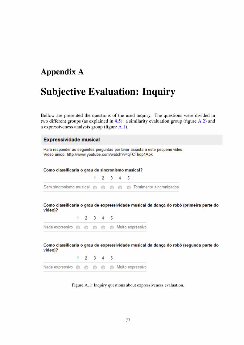
Appendix A
Subjective Evaluation: Inquiry
Bellow are presented the questions of the used inquiry. The questions were divided intwo different groups (as explained in 4.5): a similarity evaluation group (figure A.2) anda expressiveness analysis group (figure A.1).
Figure A.1: Inquiry questions about expressiveness evaluation.
77
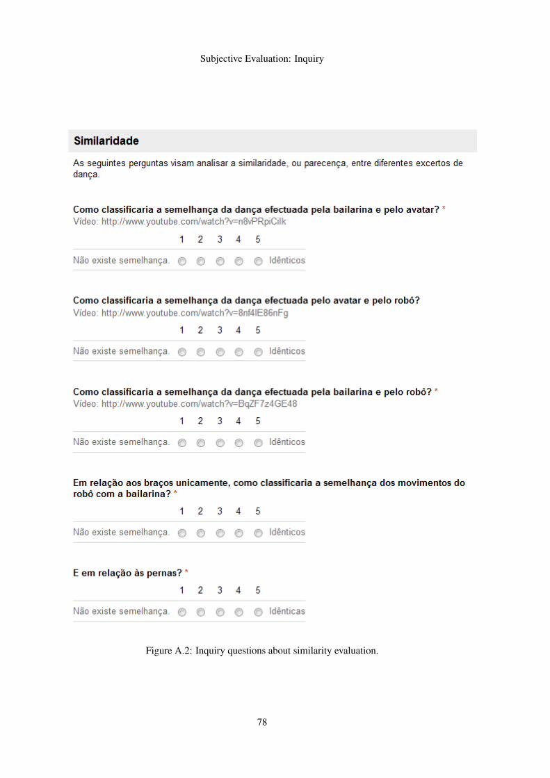
Subjective Evaluation: Inquiry
Figure A.2: Inquiry questions about similarity evaluation.
78