Embed Size (px)
Citation preview
1
Spotlight: Exploiting Smart Antennas for Future Wireless Networks
Romit Roy Choudhury
Dept. of ECE and CSDuke University

2
Collection of wireless hosts Relay packets on behalf of each other Together form an arbitrary topology May be connected to wired infrastructure
2 reasons to prefer multihop Capacity and Power constraint
Wireless Multihop Networks
B
AC
D

3
Collection of wireless hosts Relay packets on behalf of each other Together form an arbitrary topology May be connected to wired infrastructure
2 reasons to prefer multihop Capacity and Power constraint
Wireless Multihop Networks

4
Applications
Wide popularity in military
Commercial applications emerging quickly
For Example …

5
Applications
RFID and Sensor Networks
Citywatchers, WalmartIntel, Philips, Bosch …
Personal AreaNetworks
Cisco, Motorola, Intel, Samsung…
Mesh Networks andWireless Backbones
Microsoft, Intel, Cisco …
Several Challenges, Protocols
Internet

6
Internet
Omnidirectional Antennas

7
CTS = Clear To Send
RTS = Request To Send
IEEE 802.11 with Omni Antenna
D
Y
S
M
K
RTS
CTS
X

8
IEEE 802.11 with Omni Antenna
D
Y
S
X
M
Ksilenced
silenced
silenced
silencedData
ACK

9
IEEE 802.11 with Omni Antenna
DS
X
M
Ksilenced
silenced
silenced
Y
silencedData
ACK
D
silenced
E
silencedA
silencedC
silenced
F
silenced
B
silenced
G
silenced
`` Interference management ``A crucial challenge for dense multihop networks

10
Managing Interference
Several approaches Dividing network into different channels Power control Rate Control …
Our Approach …Exploiting antenna capabilities to
improve the performance of wireless multihop networks

11
From Omni Antennas …
DS
X
M
Ksilenced
silenced
silenced
Y
silenced
D
silenced
E
silencedA
silencedC
silenced
F
silenced
B
silenced
G
silenced

12
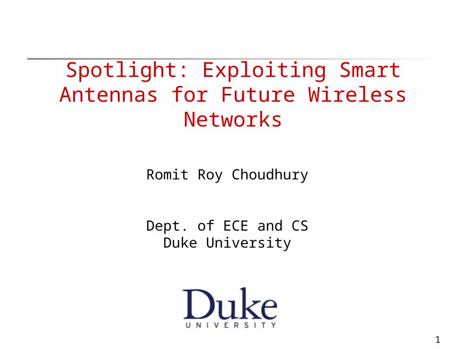
To Beamforming Antennas
DS
X
M
K
Y
D
E
A
C
F
B
G
13
To Beamforming Antennas
DS
X
M
K
Y
D
E
A
C
F
B
G

14
Outline / Contribution
Antenna Systems A closer look
New challenges with beamforming antennas
Design of MAC and Routing protocols MMAC, ToneDMAC, CaDMAC DDSR, CaRP Cross-Layer protocols – Anycasting Improved understanding of theoretical capacity
Experiment with prototype testbed

15
Antenna Systems
Signal Processing and Antenna Design research Several existing antenna systems
•Switched Beam Antennas
•Reconfigurable Antennas
•MIMO Beamforming
•MIMO Spatial Multiplexing
Many becoming commercially availableFor example …

16
Electronically Steerable Antenna [ATR Japan]
Higher frequency, Smaller size, Lower cost Capable of Omnidirectional mode and Directional
mode

17
Switched and Array Antennas
On poletop or vehicles Antennas bigger No power constraint

18
Beamforming Antenna Abstraction
3 Possible antenna modes Omnidirectional mode Single Beam mode Multi-Beam mode
Higher Layer protocols select Antenna Mode Direction of Beam

19
Antenna Beam
Energy radiated toward desired direction
A
Pictorial Model
A
Main Lobe (High gain)
Sidelobes (low gain)
20
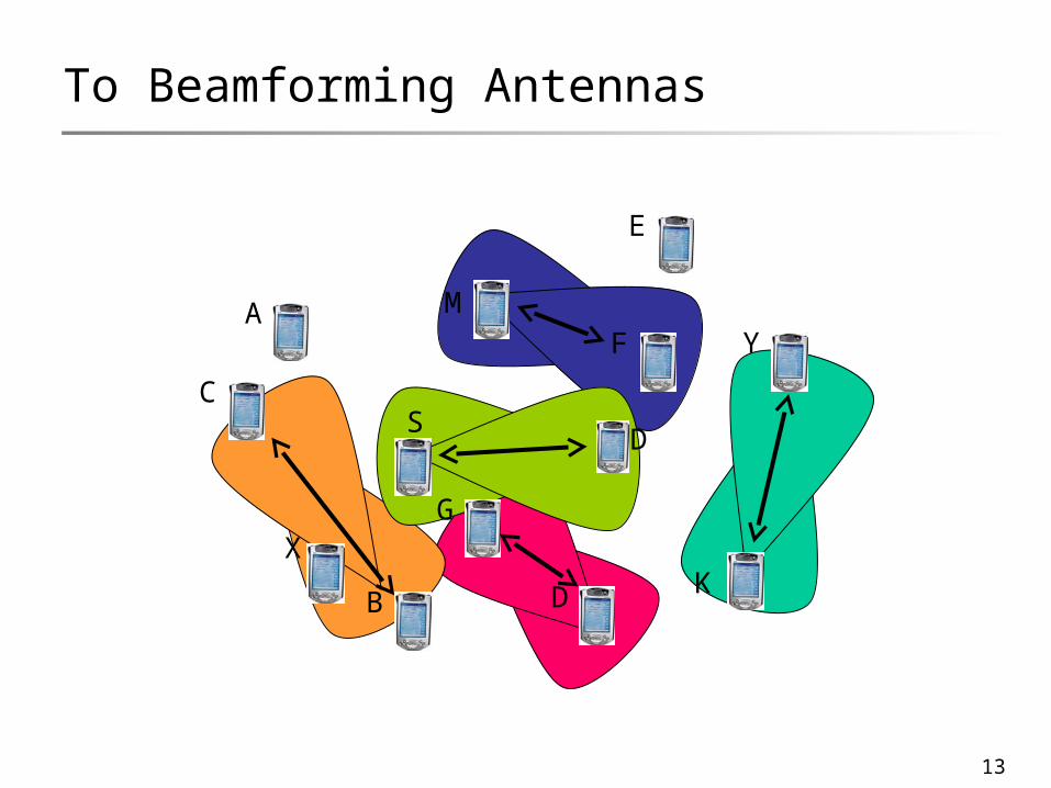
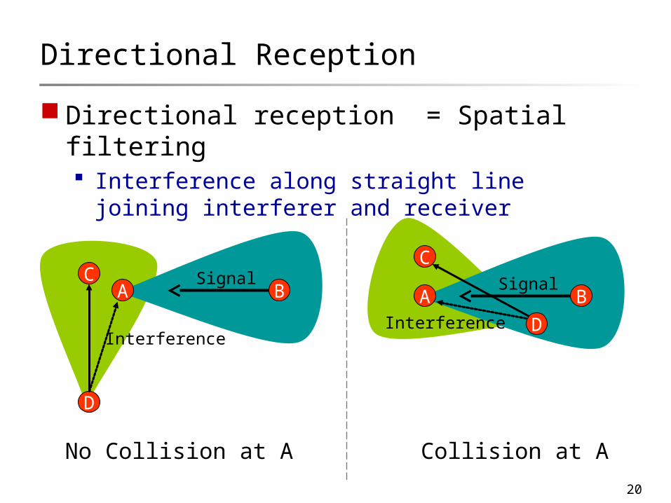
Directional Reception
Directional reception = Spatial filtering Interference along straight line joining
interferer and receiver
A BC
D
Signal
Interference
No Collision at A
A B
C
D
Signal
Interference
Collision at A

21
Will attaching such antennas at the radio layer yield most of the benefits ?
Or
Is there need for higher layer protocol support ?

22
We design a simple baseline MAC protocol(a directional version of 802.11)
We call this protocol DMAC and investigate its behavior through simulation

23
Remain omni while idle Nodes cannot predict who will trasmit to it
DMAC Example
D
Y
S
X

24
RTS
DMAC Example
D
Y
S
X
Assume S knows direction of D

25
RTS
RTSCTS
DMAC Example
D
Y
S
X
DATA/ACK
X silenced … but only toward direction of D

26
Intuitively
Performance benefits appear obvious
27
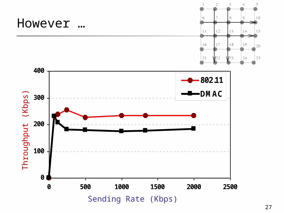
However …
0
100
200
300
400
0 500 1000 1500 2000 2500
Sending Rate (Kbps)
Aggregate Throughput (Kbps)
802.11
DMAC
Sending Rate (Kbps)
Th
rou
gh
pu
t (K
bp
s)
28
Clearly, attaching sophisticated antenna hardware is not sufficient
Simulation traces revealed various new challenges
Motivates higher layer protocol design

29
Outline / Contribution
Antenna Systems A closer look
New challenges with beamforming antennas
Design of MAC and Routing protocols MMAC, ToneDMAC, CaDMAC DDSR, CaRP Cross-Layer protocols – Anycasting Improved understanding of theoretical capacity
Experiment with prototype testbed

30
Self Interferencewith Directional MAC
New Challenges [Mobicom 02]

31
Unutilized Range [Best Paper, PWC 03]
Longer range causes interference downstream Offsets benefits
Network layer needs to utilize the long range Or, MAC protocol needs to reduce transmit power
A B CData
D
route

32
New Hidden Terminal Problemswith Directional MAC
New Challenges II …
33
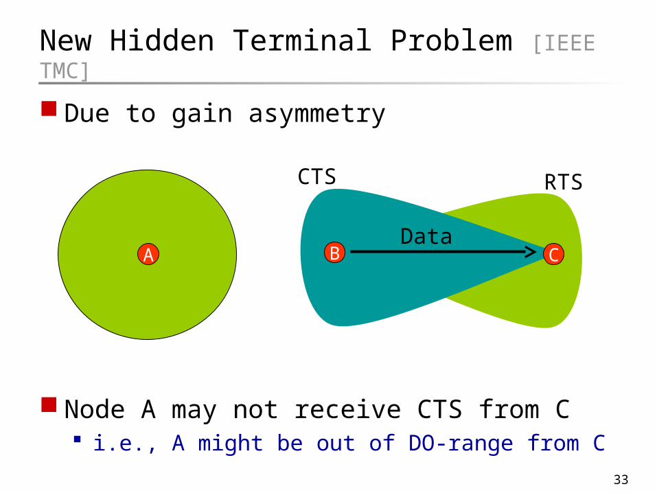
New Hidden Terminal Problem [IEEE TMC]
Due to gain asymmetry
Node A may not receive CTS from C i.e., A might be out of DO-range from C
B CAData
RTSCTS

34
New Hidden Terminal Problem
Due to gain asymmetry
Node A later intends to transmit to node B A cannot carrier-sense B’s transmission to C
B CAData
Carrier Sense
RTSCTS

35
New Hidden Terminal Problem
Due to gain asymmetry
Node A may initiate RTS meant for B A can interfere at C causing collision
B CADataRTS
Collision

36
Deafnesswith Directional MAC
New Challenges III …

37
Deafness [ICNP 04]
Node N initiates communication to S S does not respond as S is beamformed toward
D N cannot classify cause of failure Can be collision or deafness
S D
N
Data
RTS
M
38
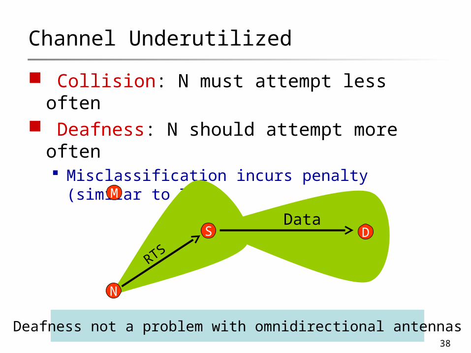
Channel Underutilized
Collision: N must attempt less often Deafness: N should attempt more often
Misclassification incurs penalty (similar to TCP)
S D
N
Data
RTS
M
Deafness not a problem with omnidirectional antennas

39
Deafness and “Deadlock”
Directional sensing and backoff ... Causes S to always stay beamformed to D X keeps retransmitting to S without success Similarly Z to X a “deadlock”
DATA
RTS
X
DS
Z
RTS

40
ToneDMAC’s Impact
Another possible improvement:
Backoff Counter for DMAC flows
Backoff Counter for ToneDMAC flows
time
Ba
cko
ff V
alu
es

41
MAC-Layer CaptureThe bottleneck to spatial reuse
New Challenges IV …

42
Typically, idle nodes remain in omni mode When signal arrives, nodes get engaged in
receiving the packet Received packet passed to MAC If packet not meant for that node, it is dropped
Capture [HotNets 03]
Wastage because the receiver could accomplish useful communication
instead of receiving the unproductive packet
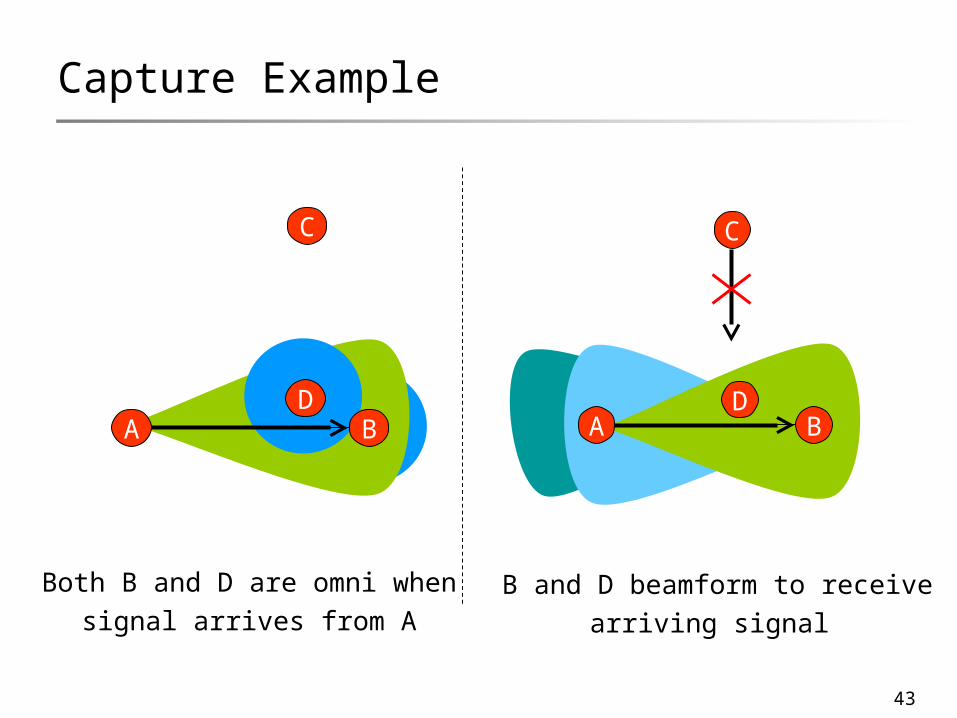
43
Capture Example
A B
C
D
Both B and D are omni whensignal arrives from A
A B
C
D
B and D beamform to receivearriving signal

44
Outline / Contribution
Antenna Systems A closer look
New challenges with beamforming antennas
Design of MAC and Routing protocols MMAC, ToneDMAC, CaDMAC DDSR, CaRP Cross-Layer protocols – Anycasting Improved understanding of theoretical capacity
Experiment with prototype testbed

45
Impact of Capture
Beamforming for transmission and reception only is not sufficient
Antenna control necessary during idle state also
A B
C
DA B
C
D

46
Capture-Aware MAC (CaDMAC) D monitors all incident traffic Identifies unproductive traffic
Beams that receive onlyunproductive packets are turned off
However, turning beams offcan prevent useful communication in future
MAC Layer Solution
A B
C
D

47
CaDMAC turns off beams periodically Time divided into cycles Each cycle consists of
1.Monitoring window + 2. Filtering window
1 2
CaDMAC Time Cycles
1 12 2
cycle
time
All beams remain ON,monitors unproductive beams
Node turns OFF unproductivebeams while it is idle.
Can avoid capture

48
CaDMAC Communication
Transmission / Reception uses only necessary single beam
When node becomes idle, it switches back to appropriate
beam pattern Depending upon current time window
A B
C
D
A B
C
D
49
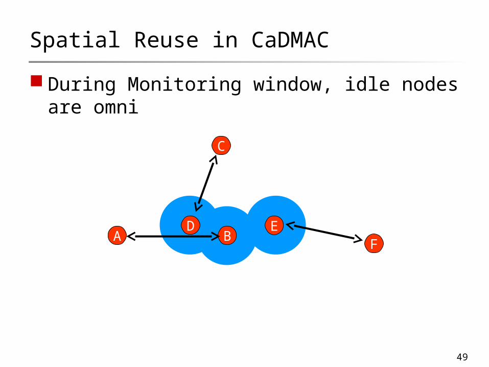
During Monitoring window, idle nodes are omni
Spatial Reuse in CaDMAC
A B
C
EF
D
50
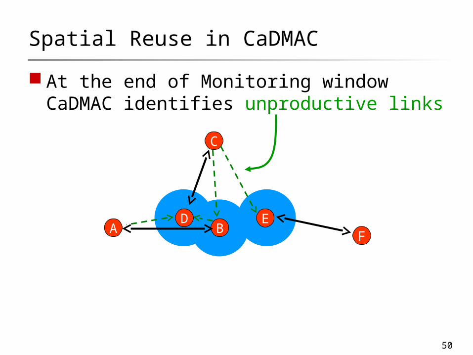
At the end of Monitoring window CaDMAC identifies unproductive links
Spatial Reuse in CaDMAC
A B
C
EF
D

51
During Filtering window use spatial filtering
Spatial Reuse in CaDMAC
A B
C
EF
D
Parallel CommunicationsCaDMAC : 3 DMAC & others : ≤ 2Omni 802.11 : 1

52
Network Transport Capacity
Transport capacity defined as:bit-meters per second
(like man-miles per day for airline companies)
Capacity analysis∑∑
= =
≥nT
bit
bith
h
hbit nTLr
λ
λ1
)(
1
∑∑= =
≤nT
bit
bith
h
AWTkrλ
1
)(
1
2 .
⎟⎠
⎞⎜⎝
⎛∞→
n
WOLimn

53
Directional Capacity
Existing results show Capacity improvement lower bounded by
Results do not consider side lobes of radiation patterns
We consider main lobe and side lobe gains (gm
and gs)
We find capacity upper bounded by
i.e., improvement of
⎟⎟⎠
⎞⎜⎜⎝
⎛
θβπ2
O
α
α
α
βπ
2
1
1
21⎟⎟⎠
⎞⎜⎜⎝
⎛
⎟⎟⎟
⎠
⎞
⎜⎜⎜
⎝
⎛
⎟⎟⎠
⎞⎜⎜⎝
⎛
s
m
g
g
n
W
⎟⎟⎟
⎠
⎞
⎜⎜⎜
⎝
⎛
⎟⎟⎠
⎞⎜⎜⎝
⎛ α2
s
m
g
gO
CaDMAC still below achievable capacity
54
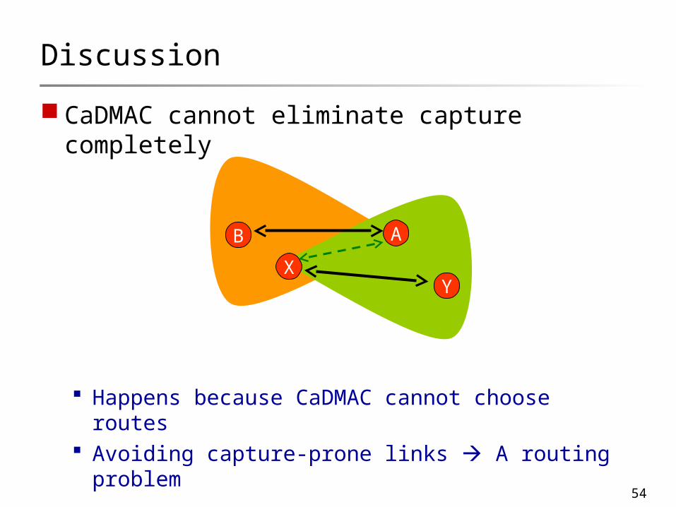
CaDMAC cannot eliminate capture completely
Happens because CaDMAC cannot choose routes Avoiding capture-prone links A routing
problem
Discussion
YX
AB
55
Routing using Beamforming AntennasIncorporating capture-awareness

56
Motivating Capture-Aware Routing
YX
AB
YX
AB
D
S
Z DZ
S
Find a route from S to D, given AB exists Options are SXYD, SXZG
Capture No Capture

57
Sum capture costs of all beams on the route Capture cost of a Beam j =
how much unproductive traffic incident on Beam j
Route’s hop count Cost of participation
How many intermediate nodes participate in cross traffic
Measuring Route Cost
X
DS

58
Uroute = Weighted Combination of1. Capture cost (K)2. Participation cost (P)3. Hop count (H)
Weights chosen based on sensitivity analysis
Unified Routing Metric
ijipijrouteij
kroute HPU ++= ∑∈
ωκω

59
Source routing protocol (like DSR) Intermediate node X updates route cost from S -
X
Destination chooses route with least cost (Uroute) Routing protocol shown to be loop-free
Protocol Design
X
DS
C1
C2
C3
C5
USX
USD = USX + C2 + C5 + PD + 1

60
CaRP Vs DSR
1
2
34

61
CaRP Vs DSR

62
CaRP Vs DSR

63
CaRP Vs DSR

64
CaRP Vs DSR

65
CaRP Vs DSR

66
CaRP Vs DSR

67
CaRP Vs DSR

68
CaRP Vs DSR
DSR CaRP
CaRP prefers a traffic-free direction“Squeezes in” more traffic in given area

69
Performance of CaDMAC
CaDMAC
DMAC
802.11
CBR Traffic (Mbps)
Ag
gre
gate
Th
rou
gh
pu
t (M
bp
s)
CMAC

70
Throughput with CaRP CaRP +CaDMAC
DSR +CaDMAC
DSR +802.11
Ag
gre
gate
Th
rou
gh
pu
t (M
bp
s)
Topology Number
Random Topologies

71
Outline / Contribution
Antenna Systems A closer look
New challenges with beamforming antennas
Design of MAC and Routing protocols MMAC, ToneDMAC, CaDMAC DDSR, CaRP Cross-Layer protocols – Anycasting Improved understanding of theoretical capacity Security
Experiment with prototype testbed

72
Security and Privacy
Growing concern in security and privacy Make make/break wireless systems
Many wireless attacks Leverage the feasibility of easy overhearing Facilitated by omnidirectional communication
New opportunities with beamforming Guide toward trusted receiver Steer away from untrusted parties Use diversity to detect malicious behavior

73
Attacker Bypassing
Feasible to ``skirt’’ around attacker Disallow from overhearing all
•MAC-Layer Anycasting
Route repair for bypassing
Cause attacker distraction
S
A
C
DB
Causing distraction
S
C
D
Unintercepted transmission

74
Verification through Diversity
Spatial diversity useful for verification Example in Sybil Attack
•Attacker pretends to be multiple entities
Privacy preserving verification possible All locations of nodes are requested Beamformed in random sequence
• In each transmission, random number transmitted
Finally, all nodes requested to report all numbers
Sybil attacker cannot be at all locations•Will be caught
75
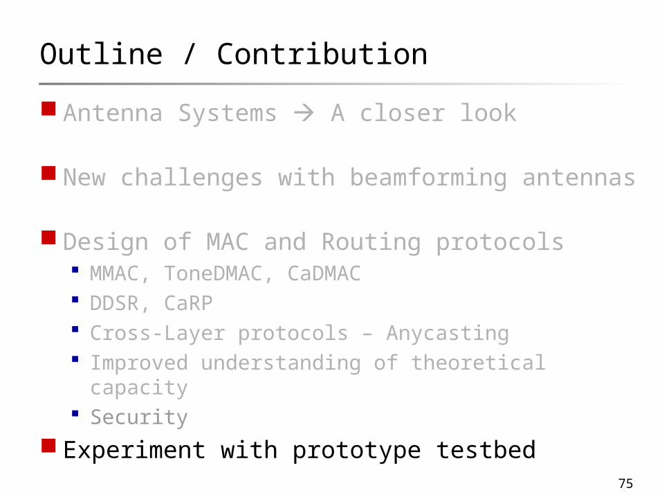
Outline / Contribution
Antenna Systems A closer look
New challenges with beamforming antennas
Design of MAC and Routing protocols MMAC, ToneDMAC, CaDMAC DDSR, CaRP Cross-Layer protocols – Anycasting Improved understanding of theoretical capacity Security
Experiment with prototype testbed

76
Testbed Prototype [VTC 05, Mobihoc 05 Poster]
Network of 6 laptops using ESPAR antennas ESPAR attached to external antenna port Beams controlled from higher layer via USB

77
Testbed Prototype
Network of 6 laptops using ESPAR antennas ESPAR attached to external antenna port Beams controlled from higher layer via USB
Validated basic operations and tradeoffs Neighbor discovery
•Observed multipath
•60 degrees beamwidth useful
Basic link state routing • Improves route stability
•Higher throughput, less delay

78
Neighbor Discovery
Non LOS and multipath important factors However, 60 degree beamwidth useful
Anechoic Chamber Office Corridor

79
Route Reliability
Routes discovered using sweeping – DO links Data Communication using DD links Improved SINR improves robustness against
fading

80
Summary
Future = Dense wireless networks Better interference management necessary
Typical approach = Omni antennas Inefficient energy management PHY layer research needs be exploited

81
Omnidirectional Antennas
Internet
82
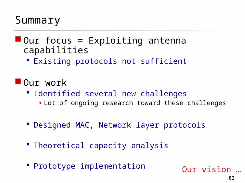
Summary
Our focus = Exploiting antenna capabilities Existing protocols not sufficient
Our work Identified several new challenges
•Lot of ongoing research toward these challenges
Designed MAC, Network layer protocols
Theoretical capacity analysis
Prototype implementation Our vision …

83
Beamforming
Internet

84
Thank You
CollaboratorsNitin Vaidya (UIUC)
Xue Yang (Intel)Ram Ramanathan (BBN)
Tetsuro Ueda (ATR Labs, Japan)

85
Backup Slides

86
Other Work
Sensor Networks Reliable broadcast [submitted]
Exploiting mobility [StoDis 05]
K-Coverage problems
Location management in mobile networks Distributed algorithms [IPDPS], [Mobihoc]
Scheduling protocols for 802.11n Combination of CSMA + TDMA schemes [WTS 04]

87
Future Work
Next generation radios (software, cognitive) PHY layer not be sufficient to harness flexibility
Example•When should a radio toggle between TDMA and CSMA
?
•Dynamic channel access needs coordination
Higher layer protocols necessary for decisions
88
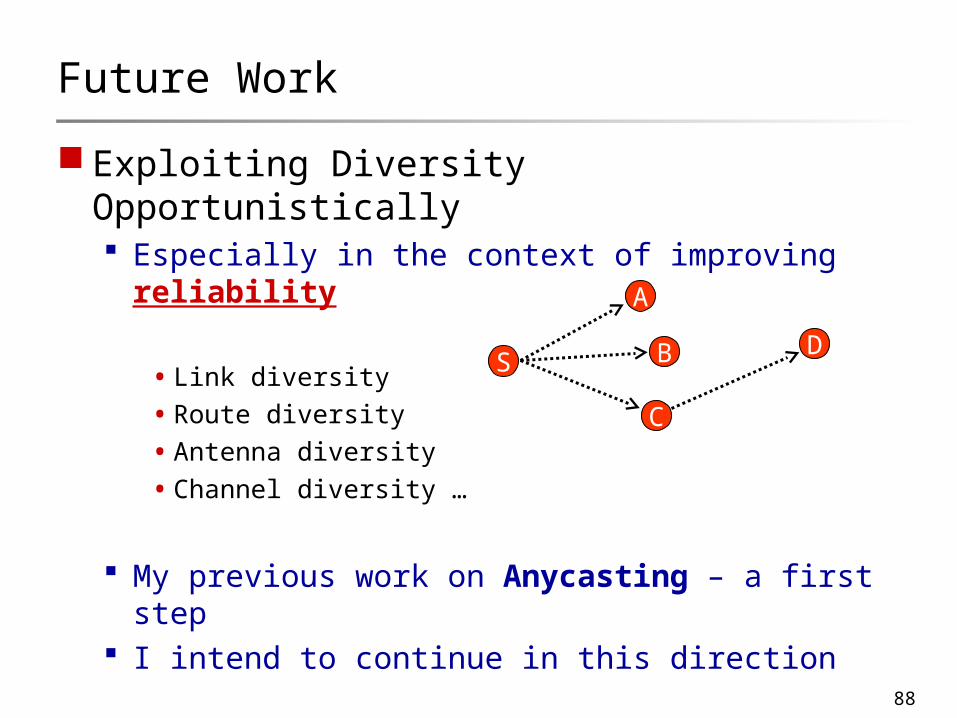
Future Work
Exploiting Diversity Opportunistically Especially in the context of improving
reliability
•Link diversity
•Route diversity
•Antenna diversity
•Channel diversity …
My previous work on Anycasting – a first step I intend to continue in this direction
S
A
B
C
D

89
Enhancing MAC [Mobicom02]
MMAC Transmit multi-hop RTS to far-away receiver Synchronize with receiver using CTS
(rendezvous) Communicate data over long links

90
Routing with Higher Range [PWC03 Best Paper]
Directional routes offer Better connectivity, fewer-hop routes
However, broadcast difficult Sweeping necessary to emulate broadcast
Evaluate tradeoffs Designed directional DSR

91
2-hop flow
DMAC
IEEE 802.11
Dea
fnes
s

92
Optimal Carrier Sense Threshold
When sidelobe abstracted to sphere with gain Gs
T
Sidelobe Gs
Mainlobe Gd
Provided, optimal CS threshold is above the Rx sensitivity thresholdi.e., min {CS_calculate, RxSensitivity}

93
Commercial Antennas …
Paratek (DRWin scanning smart antennas) Beamforming in the RF domain (instead of digital) Multiple simultaneous beams possible, each
steerable http://www.mobileinfo.com/news_2002/issue08/Paratek_Antenna.htm
Motia Inc. (Javelin appliqué to 802.11 cards) Blind beamforming in RF domain (< 2us, within pilot)
CalAmps (DirectedAP offers digital beamforming) Uses RASTER beamforming technology http://www.calamp.com/pro_802_directedap.html

94
Commercial Antennas
Belkin (Pre-N smart antenna router – Airgo tech.) Uses 3 antenna elements for adaptive
beamforming http://www.techonline.com/community/tech_group/37714
Tantivy Communications (switching < 100 nanosec) http://www.prism.gatech.edu/~gtg139k/papers/11-03-025r0-WNG-bene
fitsofSmartAntennasin802.11Networks.pdf

95
While node pairs communicate X misses D’s CTS to S No DNAV toward D
New Hidden Terminal Problem II
D
Y
S
X
DataData

96
While node pairs communicate X misses D’s CTS to S No DNAV toward D X may later initiate RTS toward D, causing
collision
New Hidden Terminal Problem II
D
Y
S
X
Data
RTS
Collision

97
Abstract Antenna Model
N conical beams
Any combination of beams can be turned on
Capable of detecting beam-of-arrival for received packet

98
Protocol Design
Numerous challenges Connectivity (nodes can be mobile) Capacity (increasing demand) Reliability (channels fluctuate) Security QoS …
Many protocols designed
One commonality among most protocols