Embed Size (px)
Citation preview

1
Spillway Ratings Spillway Ratings andand
Stability Design ProceduresStability Design Procedures
____________________________________________________SITES 2005SITES 2005
INTEGRATED DEVELOPMENT ENVIRONMENTINTEGRATED DEVELOPMENT ENVIRONMENTfor
WATER RESOURCE SITE ANALYSIS

2
OBJECTIVEOBJECTIVE
Provide understanding of:Provide understanding of:• Principal spillway ratingPrincipal spillway rating• Auxiliary spillway ratingAuxiliary spillway rating• Allowable stress approachAllowable stress approach• Cover discontinuitiesCover discontinuities

3
1st entry - principal spillway crest elevation 1st discharge = 0 cfsElev and discharge must increase
Structure TableStructure Table
4
PS TypePS Type

5
Inlet
Conduit
PS SchematicPS Schematic

6
PS InletPS Inlet

7
Example HelpExample Help

8
PS ConduitPS Conduit

9
Principal Spillway DataPrincipal Spillway Data• Number of conduits, Number of conduits,
Identical Conduits (if > 1) Identical Conduits (if > 1) • Conduit(s) size (length and diameter)Conduit(s) size (length and diameter)• Manning’s Manning’s nn value for the conduit(s), value for the conduit(s), • Hydraulic grade line at the outlet Hydraulic grade line at the outlet
(tailwater elevation)(tailwater elevation) Elevation of the center of the pipe outlet Elevation of the center of the pipe outlet Tailwater is assumed constant Tailwater is assumed constant
• SITES develops rating table SITES develops rating table spillway crest spillway crest maximum elevation in the structure tablemaximum elevation in the structure table

10
Op
tion
al
Aux Spwy EntryAux Spwy Entry

11
•
Auxiliary Spillway RatingAuxiliary Spillway Rating
• Flow resistanceFlow resistance varies varies by reach• Mixed vegetal and non-vegetal Mixed vegetal and non-vegetal
flow resistance• Seeks hydraulic control sectionSeeks hydraulic control section

12
InletNaturalGroundRch1
ConstructedInlet Channel
Rch2
ConstructedExit Channel
Rch3
Exit Natural Ground
Rch4
Tie
Sta
tion
Auxiliary Spillway ProfileAuxiliary Spillway Profile

13
Tie StationTie Station• Downstream end of the level crest Downstream end of the level crest
section of the auxiliary spillwaysection of the auxiliary spillway• Same coordinate system as Same coordinate system as
geologic materialsgeologic materials• Locates auxiliary spillway template Locates auxiliary spillway template
relative to geologic materials relative to geologic materials • Not where cowboys put horses when in Not where cowboys put horses when in
the saloonthe saloon

14
AS TemplateAS Template• Natural or existing ground profile - Natural or existing ground profile -
geology input geology input • SITES computes intersection SITES computes intersection
natural ground – constructed natural ground – constructed channel channel
• Level crest section is required!Level crest section is required!• Flow resistance may vary by reachFlow resistance may vary by reach• Vegetation or earthen lining may Vegetation or earthen lining may
change by reachchange by reach

15
SITES AS ComputationSITES AS Computation
• SITES seeks the hydraulic control SITES seeks the hydraulic control section for each discharge section for each discharge
• Backwater analysisBackwater analysis• Does exit channel reach or Does exit channel reach or
downstream natural ground downstream natural ground reaches sustain subcritical flow at reaches sustain subcritical flow at given discharge?given discharge?
16
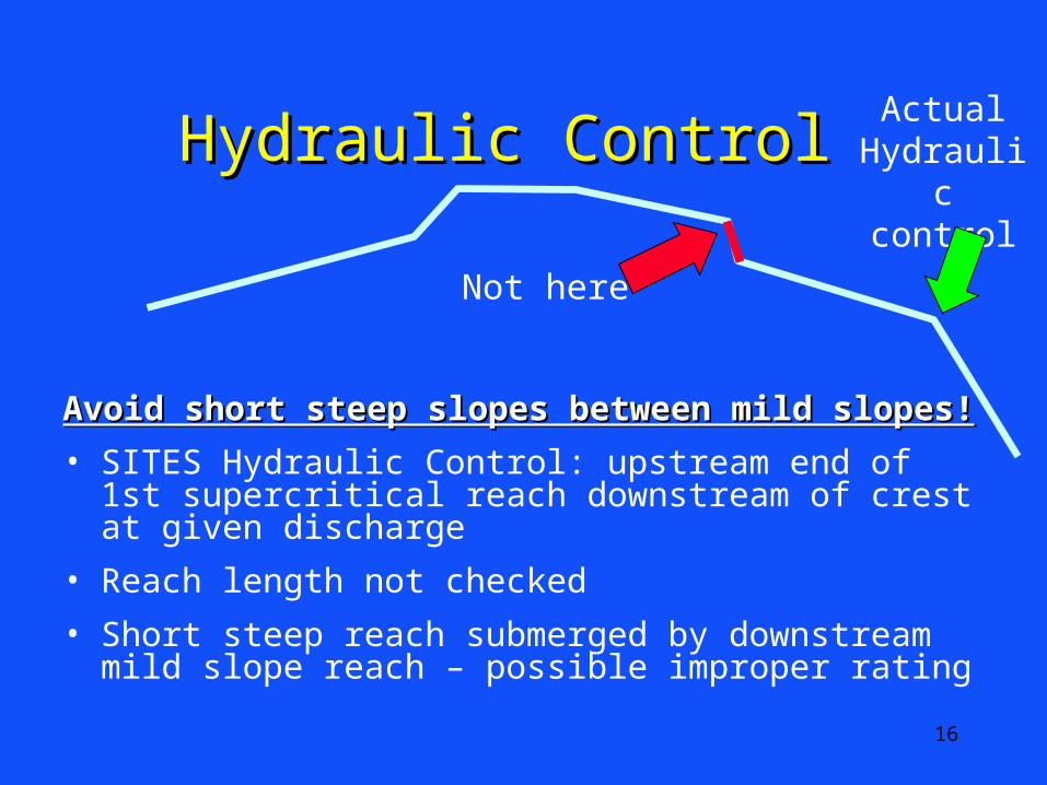
Hydraulic Control Hydraulic Control
Avoid short steep slopes between mild slopes!Avoid short steep slopes between mild slopes!
• SITES Hydraulic Control: upstream end of 1st supercritical reach downstream of crest at given discharge
• Reach length not checked
• Short steep reach submerged by downstream mild slope reach – possible improper rating
Actual Hydraulic control
Not here

17
N vs VRN vs VRA
E
DC
B
10.0
5.664.442.88
7.6
AH-667
TP-61
Man
nin
g’s
n
VR Product ft2/s0.1 1 10 100
1
0.1
0.01

18
Flow ResistanceFlow Resistance
1.1. Manning’s Manning’s nn
2.2. SCS TP-61 Retardance (A-E)SCS TP-61 Retardance (A-E)
3.3. Ag Handbook 667 Retardance Ag Handbook 667 Retardance Curve (CCurve (Cii))

19
CCII = 5.6 = 5.6
n = 0.04n = 0.04
Head-DischargeHead-Discharge
20
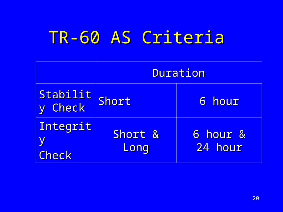
TR-60 AS Criteria TR-60 AS Criteria
DurationDuration
Stability Stability CheckCheck ShortShort 6 hour6 hour
IntegrityIntegrity
CheckCheckShort & LongShort & Long 6 hour &6 hour &
24 hour24 hour

21
Stability vs IntegrityStability vs Integrity
• StabilityStability Check Check Protect the aux spillway Protect the aux spillway SURFACESURFACE No surface erosion!No surface erosion!
• IntegrityIntegrity Check Check Some erosion accepted/expectedSome erosion accepted/expected Protect the aux spillway Protect the aux spillway LEVEL LEVEL
CRESTCREST from breaching from breaching Protect dam from overtoppingProtect dam from overtopping

22
Stability vs IntegrityStability vs Integrity
AnalysisAnalysis Hydro-Hydro-graphgraph ParameterParameter
StabilityStability SDHSDHSurface Surface erosion in erosion in aux spwy?aux spwy?
Peak stressPeak stress
IntegrityIntegrity FBHFBHLevel crest Level crest aux spwy aux spwy breached?breached?
Cumulative Cumulative erosionerosion
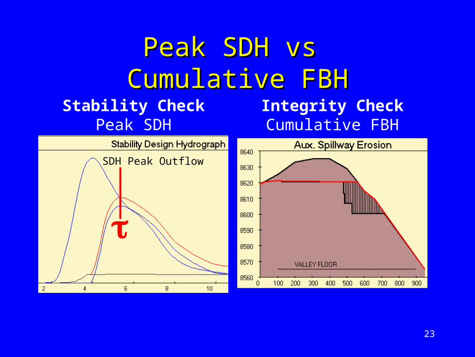
23
Peak SDH vs Peak SDH vs Cumulative FBHCumulative FBH
SDH Peak Outflow
Stability CheckPeak SDH
Integrity CheckCumulative FBH

24
After the StormAfter the StormHydro-Hydro-graphgraph
Anticipated Local Sponsor Anticipated Local Sponsor ActionAction
StabilityStability SDHSDHVerify no surface Verify no surface erosion in aux spwyerosion in aux spwy
IntegrityIntegrity FBHFBH
Verify dam level crest Verify dam level crest not breachednot breached
Fill erosion in aux spwyFill erosion in aux spwy

25
Stability Analysis Stability Analysis DefinitionDefinition
• Tractive stress of earth or Tractive stress of earth or vegetated spillway computed from vegetated spillway computed from SDH 6-hour peak dischargeSDH 6-hour peak discharge
26
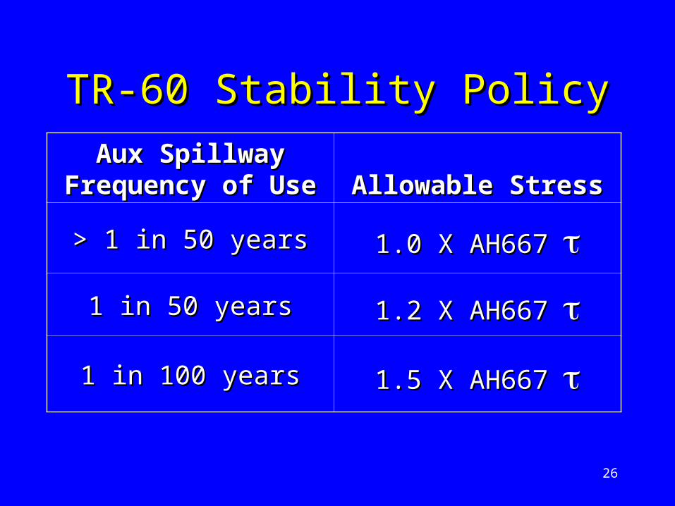
TR-60 Stability PolicyTR-60 Stability Policy
Aux Spillway Aux Spillway Frequency of UseFrequency of Use Allowable StressAllowable Stress
> 1 in 50 years> 1 in 50 years 1.0 X AH667 1.0 X AH667
1 in 50 years1 in 50 years 1.2 X AH667 1.2 X AH667
1 in 100 years1 in 100 years 1.5 X AH667 1.5 X AH667

27
SITESSITES
Auxiliary SpillwayAuxiliary SpillwayStability AnalysisStability Analysis

28
•
Stability Analysis in SITESStability Analysis in SITES
• Design variable options Design variable options Allowable stress (Allowable stress (, psf), psf) Permissible velocity (fps)Permissible velocity (fps)
• Compute optionsCompute options1.1. User enters AS widthUser enters AS width
SITES compute AS stress
2.2. User enters allowable stressUser enters allowable stress SITES compute AS width

29
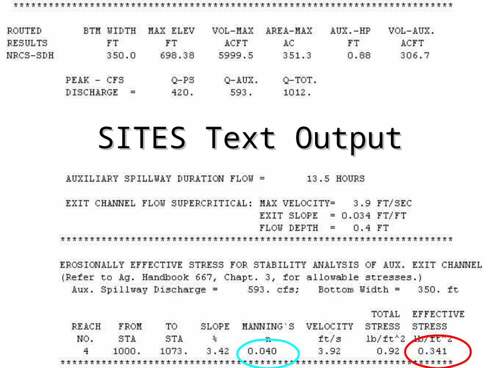
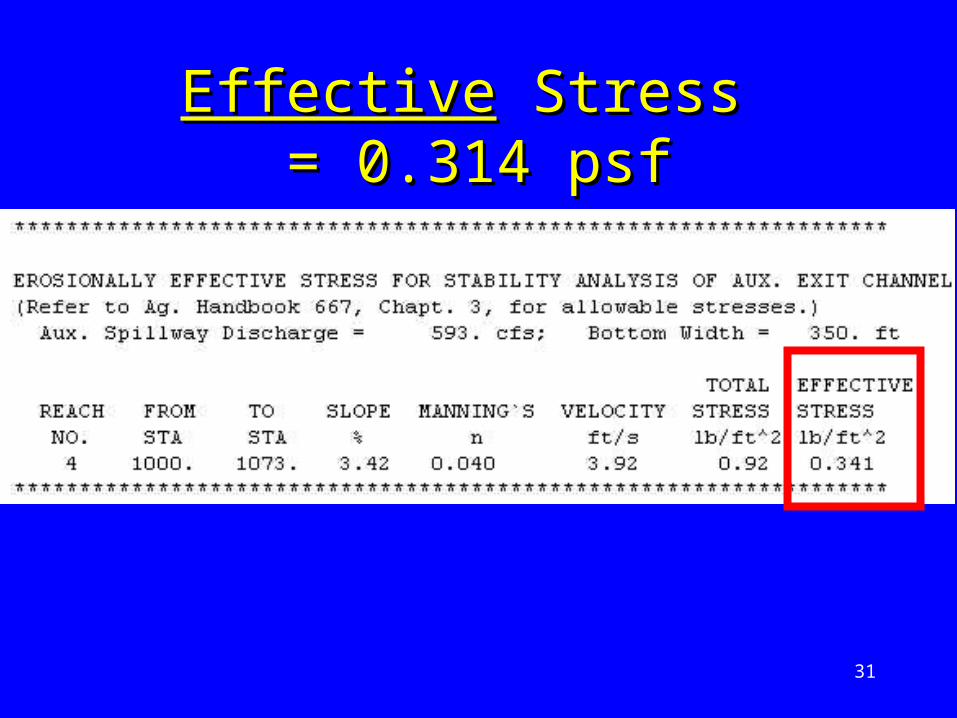
SITES Summary – 0.341 psfSITES Summary – 0.341 psf
30
SITES Text OutputSITES Text Output
31
EffectiveEffective Stress Stress = 0.314 psf= 0.314 psf

32
0.85”
AH 667 AH 667 Fig 3.1Fig 3.1 0.314 psf
• 1” grain size allowable stress ~ 0.4 psf
• 0.9” grain size meets stability requirements

33
Vegetal Erosion ProtectionVegetal Erosion Protection
total
veg
soil

34
= Total Hydraulic Stress – lb/ft2
= Vegetal Stress + Effective Soil Stress
= ve + e
Total Hydraulic StressTotal Hydraulic Stress

35
va = 0.75 Ci
Ci = Retardance Index
@ Ci = 5.6
va = 4.2 lbs/ft2
Allowable Vegetal StressAllowable Vegetal Stress

36
Vegetal Stress - LimitVegetal Stress - Limit

37
Allow Eff Soil StressAllow Eff Soil StressErodibilityErodibility Allow Eff Allow Eff
Soil StressSoil Stress Soil TypeSoil Type
Easily ErodedEasily Eroded 0.02 lb/ft0.02 lb/ft22 Weak sandyWeak sandy0<PI<80<PI<8
ErodibleErodible 0.03 lb/ft0.03 lb/ft22 CL: PI~10CL: PI~10
Erosion Erosion ResistantResistant 0.05 lb/ft0.05 lb/ft22 CL: PI~15CL: PI~15
Very Erosion Very Erosion ResistantResistant 0.07 lb/ft0.07 lb/ft22 PI >20PI >20

38
Total Stress ExceededTotal Stress Exceeded
actualactual > > allowallow

39
Cover Slope%
Erosion Resistant
Easily Eroded
Bermudagrass 0-55-10>10
876
654
Kentucky Bluegrass
0-55-10>10
765
543
Weeping Lovegrass 0-5 3.5 2.5
Permissible Velocity Permissible Velocity (ft/s)(ft/s)

40
COVERCOVER FACTOR
CF
Bermudagrass
Kentucky Bluegrass
Weeping Lovegrass
0.9
0.87
0.5
Vegetal Cover FactorVegetal Cover Factor• used to compute Effective StressEffective Stress

41
AH 667TP 61
ORDINARY FIRMORDINARY FIRMLOAMLOAM
SILT LOAMSILT LOAM
SANDY LOAMSANDY LOAM
EROSION RESISTANT
EASILY ERODED
FLOW DEPTH, ft
AV
ER
AG
E V
EL
OC
I TY
, ft/
s
Vel vs Vel vs

42
Maintenance Code InputMaintenance Code Input
43
Maintenance Code Factor Maintenance Code Factor Definitions Definitions
1.1. Uniform cover or surfaceUniform cover or surface
2.2. Minor discontinuitiesMinor discontinuities
3.3. Major discontinuitiesMajor discontinuities
44
Maintenance Code 1Maintenance Code 1
• Uniform vegetal cover Uniform vegetal cover • Standard assumption for Standard assumption for
stability design stability design

45
Maintenance Code Maintenance Code 22
• Minor discontinuities in vegetative Minor discontinuities in vegetative cover cover
• Max dimension parallel to flow:Max dimension parallel to flow: Flow depthFlow depth Stem length of vegetationStem length of vegetation
• Examples:Examples: Tire tracks perpendicular to flowTire tracks perpendicular to flow Individual small trees in spillwayIndividual small trees in spillway

46
Maintenance Code Maintenance Code 33• Major discontinuities in the cover Major discontinuities in the cover • Concentrated flow in the area of Concentrated flow in the area of
discontinuitydiscontinuity• Negates value of vegetal coverNegates value of vegetal cover• ExampleExample
Reservoir access road in spillwayReservoir access road in spillway Cattle trails up/down slopeCattle trails up/down slope
• Impractical to design stable Impractical to design stable spillway with maintenance code 3 spillway with maintenance code 3
47
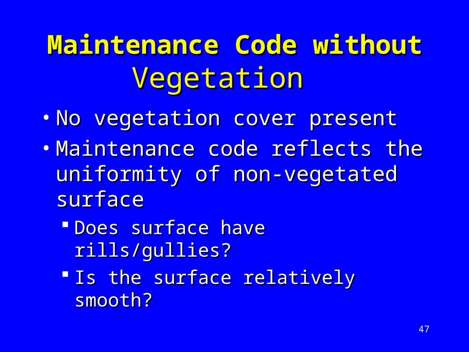
Maintenance Code Maintenance Code without without Vegetation Vegetation
• No vegetation cover present No vegetation cover present • Maintenance code reflects the Maintenance code reflects the
uniformity of non-vegetated uniformity of non-vegetated surfacesurface Does surface have rills/gullies?Does surface have rills/gullies? Is the surface relatively smooth?Is the surface relatively smooth?
48
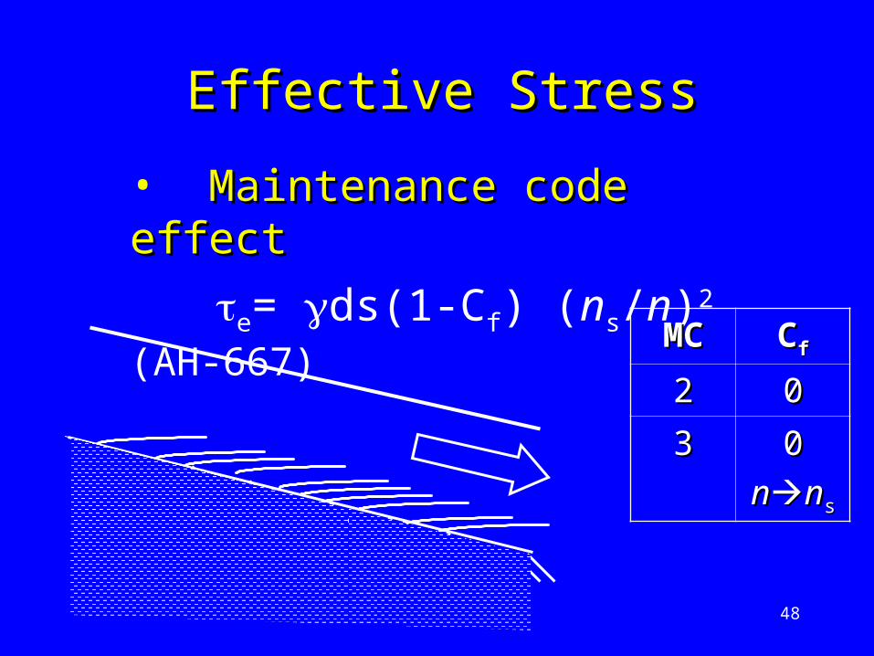
• Maintenance code effectMaintenance code effect
e= ds(1-Cf) (ns/n)2 (AH-667)
Effective StressEffective Stress
MCMC CCff
22 00
33 00
nnnnss

49
Rooting DepthRooting Depth
50
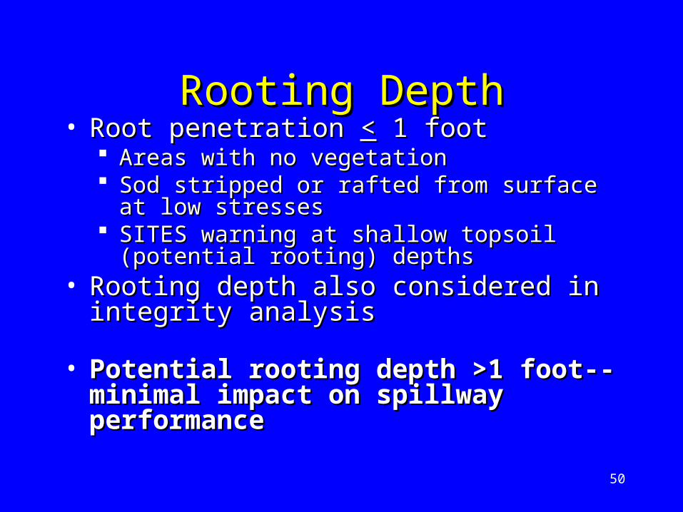
Rooting DepthRooting Depth• Root penetration Root penetration << 1 foot 1 foot
Areas with no vegetation Areas with no vegetation Sod stripped or rafted from surface at low Sod stripped or rafted from surface at low
stresses stresses SITES warning at shallow topsoil (potential SITES warning at shallow topsoil (potential
rooting) depths rooting) depths • Rooting depth also considered in Rooting depth also considered in
integrity analysis integrity analysis
• Potential rooting depth >1 foot-- Potential rooting depth >1 foot-- minimal impact on spillway minimal impact on spillway performanceperformance

51
Stability AnalysisStability Analysis SummarySummary
• Based on peak of SDHBased on peak of SDH• Applied to exit channelApplied to exit channel• Velocity Or Stress calculationsVelocity Or Stress calculations
• COMPUTE V, COMPUTE V, ee, or AS WIDTH, or AS WIDTH
• Maintenance Code for stress Maintenance Code for stress calculationscalculations
52
EndEnd