Embed Size (px)
Citation preview

1
Software Engineeringversus
Systems Engineering
John A McDermid, FREng
Professor of Software EngineeringUniversity of York
2
What is a System?
• According to the OED a system is– An organised or connected group of objects– A set or assemblage of things connected,
associated or interdependent so as to form a complex unity
• System is a very general term– A system might be a flock of geese, an
aircraft, or a set of computers ...
3
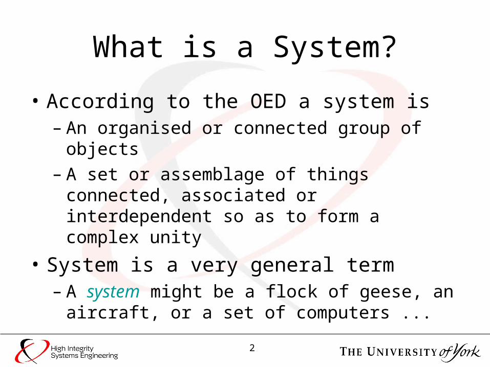
A Technical System
• This system (Typhoon) is a combination of
– Hardware, software, people, procedures …• Hardware is electro-mechanical, hydro-mechanical
structural, etc.
4
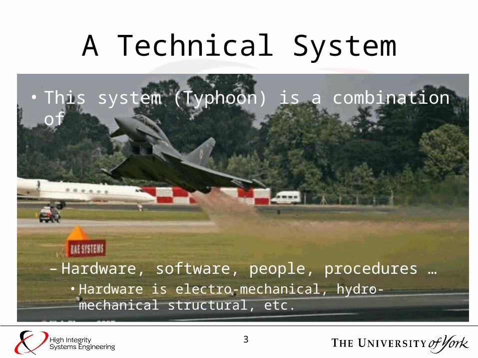
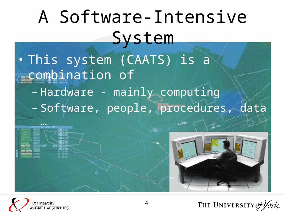
A Software-Intensive System
• This system (CAATS) is a combination of– Hardware - mainly computing– Software, people, procedures, data …
5
Systems and Software
• IT projects are undertaken to deliver some kind of business or process change
RAEng and BCS The Challenges of
Complex IT Projects (& many others)
• Hence, to be successful, software projects must address– Hardware, people, processes …– Very similar scope to systems engineering

6
Systems vs Software
• INCOSE Process Summary
• Scope ofsoftwareengineering?– Software
technologyonly
Enterprise Environment Management
Investment Management
System Lifecycle Process
Management
Resource Management
Quality Management
Enterprise Processes
AgreementProcesses
Acquisition
Supply
Process Guidelines
Project Processes
Technical Processes
Planning Assessment Control
Decision Making
Risk Management
Configuration Management
Information Management
Stakeholder Requirements
Definition
Requirements Analysis
Architectural Design
Implementation Integration
Verification Transition Validation
Operation Maintenance
Disposal
7
Some Questions (1)
• Do systems & software require different modelling languages?– E.g. SysML or MoDAF vs UML or AADL
• Do technical systems & software intensive systems require different architectures?– SOA appropriate for SIS, embedded in an
organisation– Event driven for technical systems
8
Some Questions (2)
• What is the most effective relationship between systems & software engineering?– Systems led, for technical systems – Software led, for software intensive systems
• Systems engineering can be viewed as “the art of the trade-off”– How can we ensure system trade-offs reflect
software properties and process risks?

9
Some Questions (3)
• What can systems engineering learn from software engineering?– e.g. disciplined approach to cost estimation
• What can software engineering learn from systems engineering?– e.g. consideration of trade-offs and use of
“framework methods” such as QFD

10
Some Questions (4)
• How can systems & software engineering be taught to communicate the realities of complex systems development?– Educating academics– Educating students
• For complex systems are systems and software engineering really distinct?– Will they converge or diverge?
11
Software Engineeringin harmony with
Systems Engineering
12
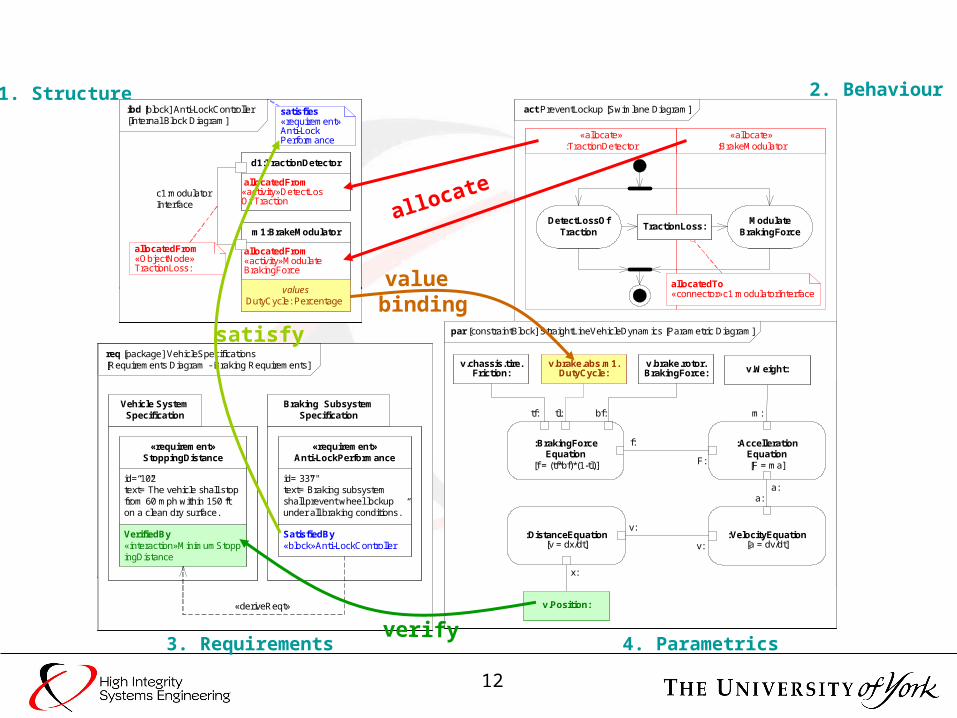
req [package] VehicleSpecifications [Requirements Diagram - Braking Requirements]
Braking Subsystem Specification
Vehicle System Specification
id=“102”text=”The vehicle shall stop from 60 mph within 150 ft on a clean dry surface.”
«requirement»StoppingDistance
id=”337"text=”Braking subsystem shall prevent wheel lockup under all braking conditions.”
«requirement»Anti-LockPerformance
«deriveReqt»
req [package] VehicleSpecifications [Requirements Diagram - Braking Requirements]
Braking Subsystem Specification
Vehicle System Specification
id=“102”text=”The vehicle shall stop from 60 mph within 150 ft on a clean dry surface.”
«requirement»StoppingDistance
SatisfiedBy«block»Anti-LockController
id=”337"text=”Braking subsystem shall prevent wheel lockup under all braking conditions.”
«requirement»Anti-LockPerformance
«deriveReqt»
act PreventLockup [Activity Diagram]
DetectLossOf Traction
Modulate BrakingForce
TractionLoss:
par [constraintBlock] StraightLineVehicleDynamics [Parametric Diagram]
:AccellerationEquation[F = ma]
:VelocityEquation[a = dv/dt]
:DistanceEquation[v = dx/dt]
:BrakingForceEquation
[f = (tf*bf)*(1-tl)]
tf: bf:tl:
f:
F:
c
a:a:
v:
v:
x:
ibd [block] Anti-LockController [Internal Block Diagram]
d1:Traction Detector
m1:Brake Modulator
c1:modulator interface
1. Structure 2. Behaviour
3. Requirements 4. Parametrics
act PreventLockup [Swimlane Diagram]
«allocate»:TractionDetector
«allocate»:BrakeModulator
allocatedTo«connector»c1:modulatorInterface
DetectLossOf Traction
Modulate BrakingForce
TractionLoss:
ibd [block] Anti-LockController [Internal Block Diagram]
allocatedFrom«activity»DetectLosOfTraction
d1:TractionDetector
allocatedFrom «activity»Modulate BrakingForce
m1:BrakeModulator
allocatedFrom«ObjectNode»TractionLoss:
c1:modulatorInterface
ibd [block] Anti-LockController [Internal Block Diagram]
allocatedFrom«activity»DetectLosOfTraction
d1:TractionDetector
allocatedFrom «activity»Modulate BrakingForce
m1:BrakeModulator
allocatedFrom«ObjectNode»TractionLoss:
c1:modulatorInterface
satisfies«requirement»Anti-LockPerformance
ibd [block] Anti-LockController [Internal Block Diagram]
allocatedFrom«activity»DetectLosOf Traction
d1:TractionDetector
valuesDutyCycle: Percentage
allocatedFrom «activity»Modulate BrakingForce
m1:BrakeModulator
allocatedFrom«ObjectNode»TractionLoss:
c1:modulatorInterface
satisfies«requirement»Anti-LockPerformance
allocate
par [constraintBlock] StraightLineVehicleDynamics [Parametric Diagram]
:AccellerationEquation[F = ma]
:VelocityEquation[a = dv/dt]
:DistanceEquation[v = dx/dt]
:BrakingForceEquation
[f = (tf*bf)*(1-tl)]
tf: bf:tl:
f:
F:
m:
a:a:
v:
v:
x:
v.Position:
v.Weight:v.chassis.tire.
Friction:v.brake.abs.m1.
DutyCycle:v.brake.rotor.BrakingForce:
value binding
req [package] VehicleSpecifications [Requirements Diagram - Braking Requirements]
Braking Subsystem Specification
Vehicle System Specification
VerifiedBy«interaction»MinimumStoppingDistance
id=“102”text=”The vehicle shall stop from 60 mph within 150 ft on a clean dry surface.”
«requirement»StoppingDistance
SatisfiedBy«block»Anti-LockController
id=”337"text=”Braking subsystem shall prevent wheel lockup under all braking conditions.”
«requirement»Anti-LockPerformance
«deriveReqt»
satisfy
verify
13
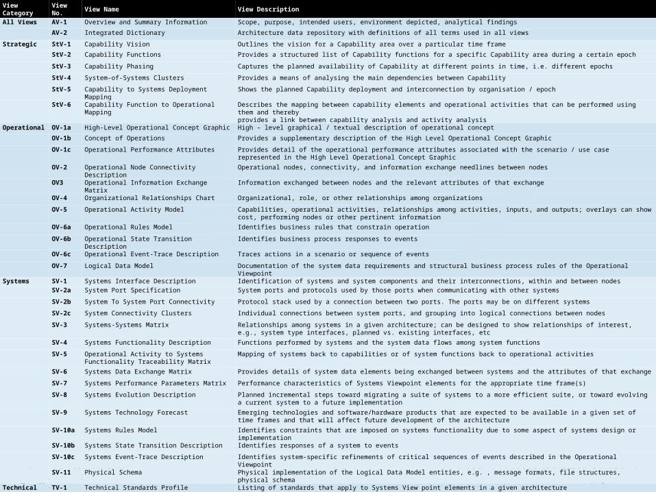
ViewCategory
View No.
View Name View Description
All Views AV-1 Overview and Summary Information Scope, purpose, intended users, environment depicted, analytical findings
AV-2 Integrated Dictionary Architecture data repository with definitions of all terms used in all views
Strategic StV-1 Capability Vision Outlines the vision for a Capability area over a particular time frame
StV-2 Capability Functions Provides a structured list of Capability functions for a specific Capability area during a certain epoch
StV-3 Capability Phasing Captures the planned availability of Capability at different points in time, i.e. different epochs
StV-4 System-of-Systems Clusters Provides a means of analysing the main dependencies between Capability
StV-5 Capability to Systems Deployment Mapping Shows the planned Capability deployment and interconnection by organisation / epoch
StV-6 Capability Function to Operational Mapping Describes the mapping between capability elements and operational activities that can be performed using them and therebyprovides a link between capability analysis and activity analysis
Operational OV-1a High-Level Operational Concept Graphic High – level graphical / textual description of operational concept
OV-1b Concept of Operations Provides a supplementary description of the High Level Operational Concept Graphic
OV-1c Operational Performance Attributes Provides detail of the operational performance attributes associated with the scenario / use case represented in the High Level Operational Concept Graphic
OV-2 Operational Node Connectivity Description Operational nodes, connectivity, and information exchange needlines between nodes
OV3 Operational Information Exchange Matrix Information exchanged between nodes and the relevant attributes of that exchange
OV-4 Organizational Relationships Chart Organizational, role, or other relationships among organizations
OV-5 Operational Activity Model Capabilities, operational activities, relationships among activities, inputs, and outputs; overlays can show cost, performing nodes or other pertinent information
OV-6a Operational Rules Model Identifies business rules that constrain operation
OV-6b Operational State Transition Description Identifies business process responses to events
OV-6c Operational Event-Trace Description Traces actions in a scenario or sequence of events
OV-7 Logical Data Model Documentation of the system data requirements and structural business process rules of the Operational Viewpoint
Systems SV-1 Systems Interface Description Identification of systems and system components and their interconnections, within and between nodes SV-2a System Port Specification System ports and protocols used by those ports when communicating with other systems
SV-2b System To System Port Connectivity Protocol stack used by a connection between two ports. The ports may be on different systems
SV-2c System Connectivity Clusters Individual connections between system ports, and grouping into logical connections between nodes
SV-3 Systems-Systems Matrix Relationships among systems in a given architecture; can be designed to show relationships of interest, e.g., system type interfaces, planned vs. existing interfaces, etc
SV-4 Systems Functionality Description Functions performed by systems and the system data flows among system functions
SV-5 Operational Activity to Systems Functionality Traceability Matrix
Mapping of systems back to capabilities or of system functions back to operational activities
SV-6 Systems Data Exchange Matrix Provides details of system data elements being exchanged between systems and the attributes of that exchange
SV-7 Systems Performance Parameters Matrix Performance characteristics of Systems Viewpoint elements for the appropriate time frame(s)
SV-8 Systems Evolution Description Planned incremental steps toward migrating a suite of systems to a more efficient suite, or toward evolving a current system to a future implementation
SV-9 Systems Technology Forecast Emerging technologies and software/hardware products that are expected to be available in a given set of time frames and that will affect future development of the architecture
SV-10a Systems Rules Model Identifies constraints that are imposed on systems functionality due to some aspect of systems design or implementation
SV-10b Systems State Transition Description Identifies responses of a system to events
SV-10c Systems Event-Trace Description Identifies system-specific refinements of critical sequences of events described in the Operational Viewpoint
SV-11 Physical Schema Physical implementation of the Logical Data Model entities, e.g. , message formats, file structures, physical schema
Technical TV-1 Technical Standards Profile Listing of standards that apply to Systems View point elements in a given architecture
TV-2 Technical Standards Forecast Description of emerging standards and potential impact on current Systems Viewpoint elements, within a set of time frames
Acquisition AcV-1 System-of-Systems Acquisition Clusters Provides detail of how Acquisition tasks are grouped to improve management of interoperability and programmatic dependencies
AcV-2 System-of-Systems Acquisition Provides an overview of either the complete acquisition Programme or a subset of projects
14
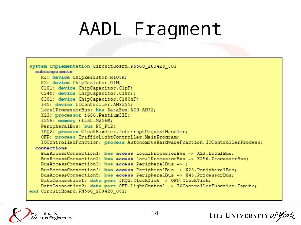
AADL Fragment
15
Viewpoint: Function S Severity of Occurrence Criticality Index Date................................
No: ....
System: Washing MachineO Probability of Occurrence C I = SOD
Author: .......................... Issue
Subsystem: ......................................D Probability of Detection
Checked: ....................... ...........
FUNCTIONCHARACTERISTICS OF FAILURE INDEX
MODE EFFECTS CAUSE O S D CI COMMENTS
LOAD DIRTY CLOTHES
DETERMINE LOAD MAKEUP
OVERLOAD
UNDERLOAD
EXTREME MIX OFLOAD
INCORRECT LOADMAKE UPINDENTIFIED
POOR WASH
POOR WASH
POSSIBLE COLOURRUN
FABRIC SHRINK
POOR WASH
POSSIBLE COLOURRUN
FABRIC SHRINK
USER ERROR
USER ERROR
EXTREMES NOTIDENTIFIED
EXTREMES NOTIDENTIFIED
ITEM OF CLOTHINGNOT INDENTIFIED
6
4
8
4
4
6
4
8
8
8
3
3
3
3
3
108
48
96
96
96
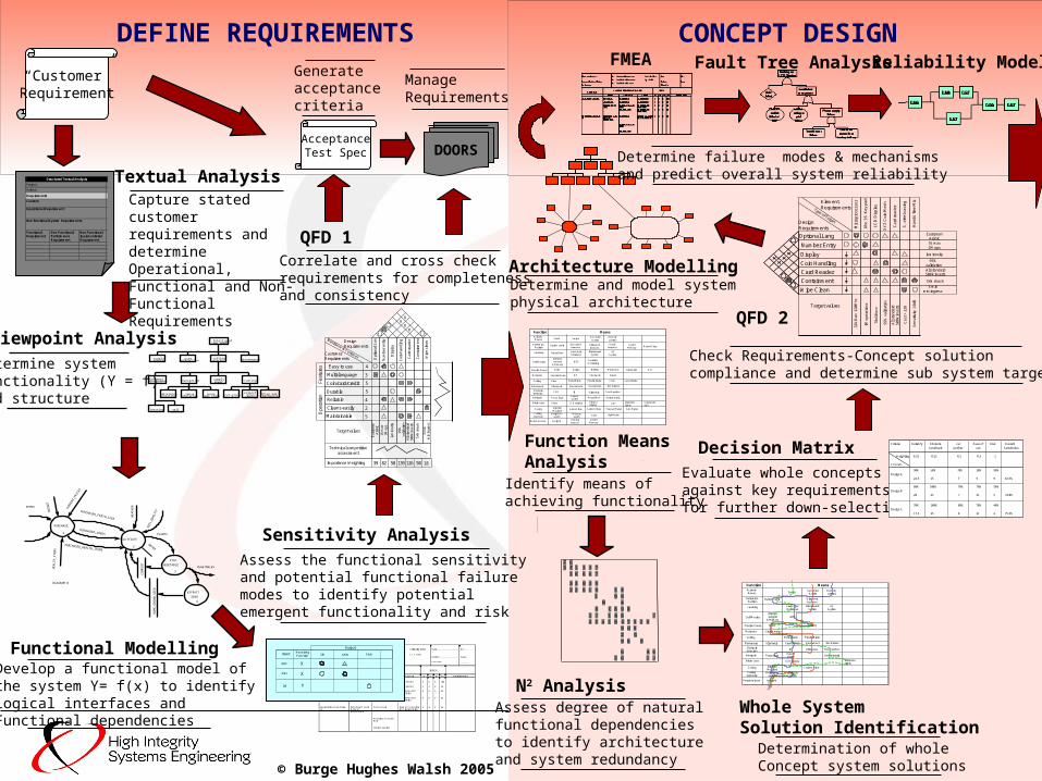
“Customer”Requirement
Textual AnalysisCapture stated customerrequirements and determine Operational, Functional and Non-Functional Requirements
N2 AnalysisWhole System Solution Identification
Function Means AnalysisIdentify means ofachieving functionality
Assess degree of natural functional dependenciesto identify architecture and system redundancy
Determination of whole Concept system solutions
DEFINE REQUIREMENTS
© Burge Hughes Walsh 2005
Structured Textual Analysis
Project:
Author:
Requirements
Context:
Operational Requirement:
Non functional System Requirements:
Functional Requirement
Non Functional Performance Requirement
Non Functional Implementation Requirement
userinteraction maintenance cutting
process
IntelligentLawn mower
supplymachine
navigation supplypower cutting
cut grasscollect grass
cuttingsdrive andmanoeuvre
determineposition
senseobstacles
senselawn state
internalmanagement
learning selfmonitor
Viewpoint Analysis
Determine system functionality (Y = f) and structure
Functional ModellingDevelop a functional model ofthe system Y= f(x) to identifylogical interfaces and Functional dependencies
PURCHASE
1
CULTIVATE
2
PICK
VEGETABLE
3
EXTRACT
SEED
4
CU
RR
EN
T_PR
ICE
S
BU
DG
ET
HE
ALT
H_I
TE
MS
PURCHASED_SEEDS
PURCHASED_FERTILIZER
PURCHASED_HEALTH_ITEMS
CO
MP
OS
T
VEGETABLES
HO
ME
_GR
OW
N_S
EE
D
DIAGRAM 0
WE
AT
HE
R
SO
IL_Q
UA
LITY
PLANTS
SEEDS
WATER
Input ReceivingFunction
Output
ABC
DEF
IJK
X
X
Y
IJK LMN PQR
Sensitivity AnalysisAssess the functional sensitivity and potential functional failure modes to identify potential emergent functionality and risk
Correlate and cross checkrequirements for completenessand consistency
QFD 1
DOORS
ManageRequirements
AcceptanceTest Spec
Generateacceptance criteria
CONCEPT DESIGN
Function MeansActivateMower Voice Switch
Sun-shine& date
Determine Position
Buried cable Bar codedbeacons
Learning Neural Net Lawn mapDatabase
Self MonitorInternal sensors
& MemoryBITE
Provide Power Solar Petrol
Motivator Electric Motor
Cutting Drum Metal Blade
Manoeuvre All wheels Front wheel
Obstacledetection
CCD IR Ultrasonic
Fuzzy logicExpertsystem
Touch probes
Navigate
Remotecontrol
Ultrasonicbeacons
Radiobeacons
LearntMemory
Battery Microwave Clockwork
ICE Clockwork
Neural Net Deterministic
Inform user Voice LCD display Plasmadisplay CRT Indicator
lightsClockworkdial
Casing InjectionMoulded
Glass Fibre Pressed MetalCarbon Fibre Fab. Metal
Raised Edge
BlackboardSystem
CordPlastic Blade Laser Blade
Rear wheel Ind. Brakes
Cutting exposure
Weight Onswitch
Mercuryswitch
Gyro Light beam
Return to base navigate Homingbeacon
LearntMemory
Condition monitoring
AI System
Steam
Gas
Function MeansActivateMower Switch
Sun-shine& date
Determine Position
Buried cable
Learning Lawn mapDatabase
Self MonitorInternal sensors
& MemoryBITE
Provide Power Solar
Motivator Electric Motor
Cutting Metal Blade
Manoeuvre All wheels Front wheel
Obstacledetection
IR Ultrasonic
Fuzzy logicExpertsystem
Touch probes
Navigate
Remotecontrol
Ultrasonicbeacons
Battery
Deterministic
Inform user LCD display Indicatorlights
Casing InjectionMoulded
Carbon Fibre
BlackboardSystem
Plastic Blade
Rear wheel Ind. Brakes
Cutting exposure
Weight Onswitch
Mercuryswitch
Return to base navigate
AI System
Decision MatrixEvaluate whole conceptsagainst key requirementsfor further down-selection
Concepts
Criteria Reliab’ty Obstacle cut Ease of Risk Overall
Avoid/safe perform’ use Satisfaction
Weighting 0.25 0.25 0.1 0.3 .1
90% 50% 70% 30% 90%
Design A
22.5 15 7 9 9 62.5%
80% 100% 70% 70% 50%
Design B
20 25 7 21 5 78.0%
70% 100% 80% 70% 40%
Design C
17.5 25 8 21 4 75.5%
QFD 2
Check Requirements-Concept solution compliance and determine sub system targets
Architecture Modelling
Number Entry
Display
Coin Handling
Card Reader
Containment
Wipe Clean
DesignRequirements
Element Requirements
Mic
rop
roce
sso
r
Ab
c1
6 K
ey
pa
d
Ca
rd r
ea
de
r
XY
Z C
oin
Me
ch
S.
ste
el c
asi
ng
Ha
nd
s fr
ee
Mic
Optional Lang
LC
D D
isp
lay
xxx
xxx
x
x
EuropeanArabic16 max1M ops
luminosity
95%validationAll standard500k inserts
1kN shock
3 minmin ingress
Target values
32k
Ram
120
Mhz
IM o
pera
tions
70x5
0 m
m
95%
val
idat
ion
Cos
t < £
28
All
stan
dard
500k
inse
rts
Sen
sitiv
ity -
10dB
Type of Target
Determine and model systemphysical architecture
FMEA Reliability ModelFault Tree Analysis
Determine failure modes & mechanismsand predict overall system reliability
Multi-language
Coin/card/credit
Durable
Reliable
Cleans easily
Maintainable
CustomerRequirements
Design Requirements
Opt
iona
l La
n
Num
ber
entr
y
Car
d re
ader
Coi
n ha
ndlin
g
Con
tain
men
t
Wip
e cl
ean
3
5
5
4
2
5
Importance Weighting 5839 82 139 126 50 18
x
xx
Easy to use
Fea
ture
sO
pera
tion
4
Dis
play
x
Eur
opea
nA
rabi
c
16 m
ax1M
ops
lum
inos
ity
95%
valid
atio
nA
ll st
anda
rd50
0k in
sert
s
1kN
sho
ck
3 m
inm
in in
gres
sTarget values
Technical competitiveassessment
J262
6A6
D89
G2
9H9
9297O91454
78N173
898C8
4M
89I
419L622
93B33
766K1
7331E36F
J262
6A6
D89
G2
9H9
9297O91454
78N173
898C8
4M
89I
419L622
93B33
766K1
7331E36F