Embed Size (px)
Citation preview
1 Severn Trent Raw Water Reservoir Surveillance Training Manual 2018
Maintaining the safety of our reservoirsRaw water reservoir surveillance training manual

3Severn Trent Raw Water Reservoir Surveillance Training Manual 2018
We have the following goal:
“ We are recognised as the best in the country at reservoir safety.”
You, in wholesale operations, are part of the team that will achieve this goal by highlighting any changes in the behaviour of our reservoirs.
Even though we can group our dams into the four separate categories of raw water reservoirs, service reservoirs, flood balancing reservoirs and waste water lagoons, within each group, each dam is unique and different.
This training document deals with raw water reservoirs and flood balancing reservoirs. For information on service reservoir and waste water lagoons, please see other training booklets in this series.
Published by: Severn Trent Water Ltd
Copyright: Severn Trent Water, PO Box 5309, Coventry CV3 9FHAll rights reserved. No part of this book may be reprinted or reproduced or utilized in any form or by any electronic, mechanical or other means, now known or hereafter invented, including photocopying and recording, or in any information storage or retrieval system, without the permission in writing from the publishers.
ISBN 978-0-9526232-1-2
Third Edition November 2018
Foreword“Our reservoirs are essential to us. We cannot supply our customers without them.
Reservoir failure presents a real danger to the public and is one of the biggest risks that we face.
So we need to look after our reservoirs very carefully indeed.
We have a dedicated team of reservoir experts but you play a vital role too. Reservoir structures are complex but small changes, such as a wet patch of earth, can give us a clue that there are issues.
Your continued vigilance in looking for these changes every day or every week is essential. This training manual will help you to understand and carry out your role.
Please remember that it is often riskier walking around a reservoir than on normal pathways.
It can be done safely but it requires skill and care; please ensure that you have the equipment, procedures and capability to work safely at all times.”
Production Director
Our organisational structure for reservoir safety
Chief Engineer Review Panel
CEO
Network Control & Asset Management Operations Dams and Reservoirs
Manager
Survey TeamSupervising Engineers
Reservoir Technicians
2 Severn Trent Raw Water Reservoir Surveillance Training Manual 2018
James Jesic Production Director
Members of ST’s Review Panel and Chief Engineer’s leadership team visiting Thornton Reservoir
54 Severn Trent Raw Water Reservoir Surveillance Training Manual 2018
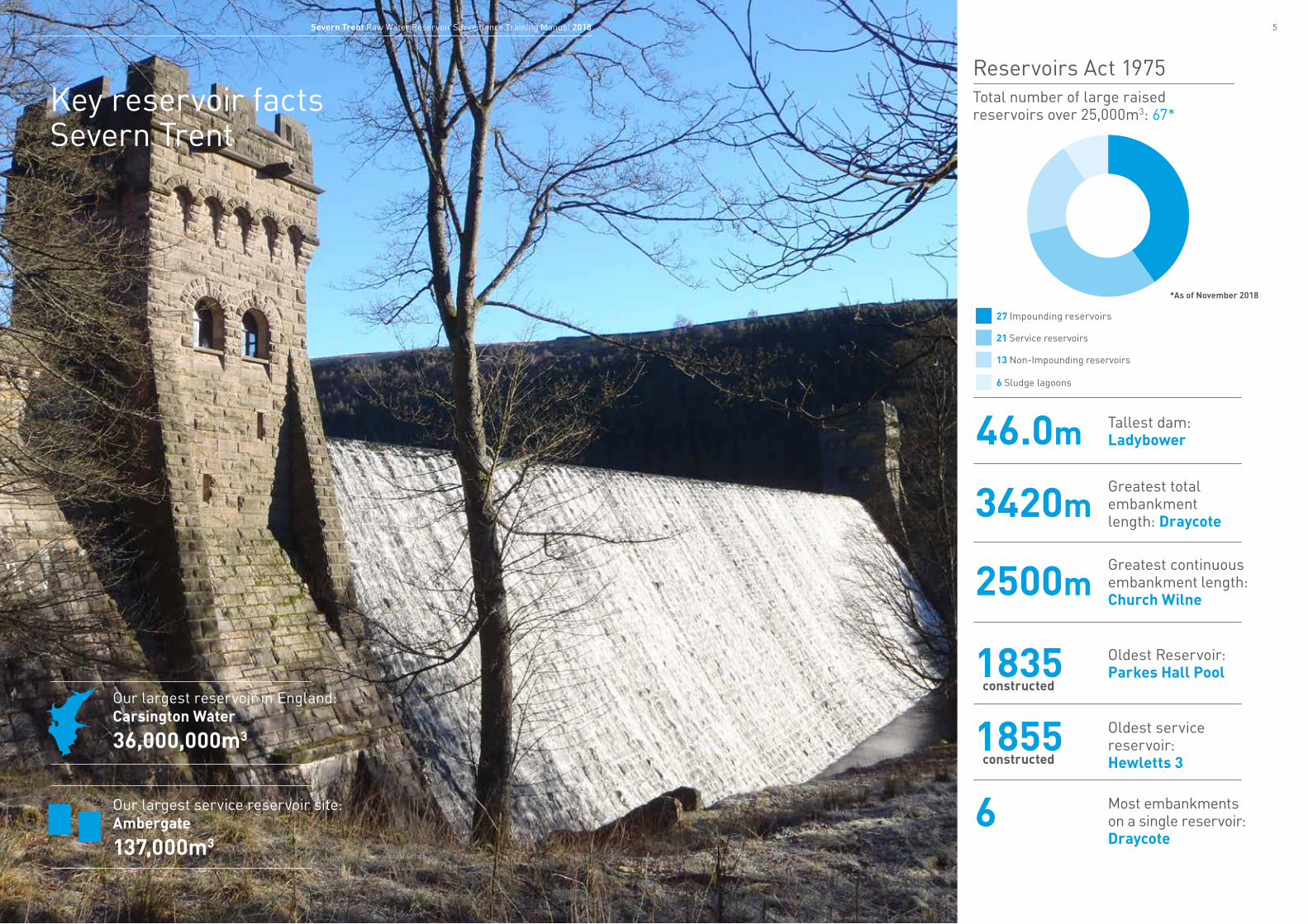
Key reservoir facts Severn Trent
Our largest reservoir in England: Carsington Water
36,000,000m3
Our largest service reservoir site: Ambergate
137,000m3
Tallest dam: Ladybower46.0mGreatest total embankment length: Draycote
3420m
Greatest continuous embankment length: Church Wilne
2500m
Oldest Reservoir: Parkes Hall Pool1835Oldest service reservoir: Hewletts 3
Most embankments on a single reservoir: Draycote
1855
6constructed
constructed
Total number of large raised reservoirs over 25,000m3: 67*
*As of November 2018
27 Impounding reservoirs
21 Service reservoirs
13 Non-Impounding reservoirs
6 Sludge lagoons
Reservoirs Act 1975
76 Severn Trent Raw Water Reservoir Surveillance Training Manual 2018
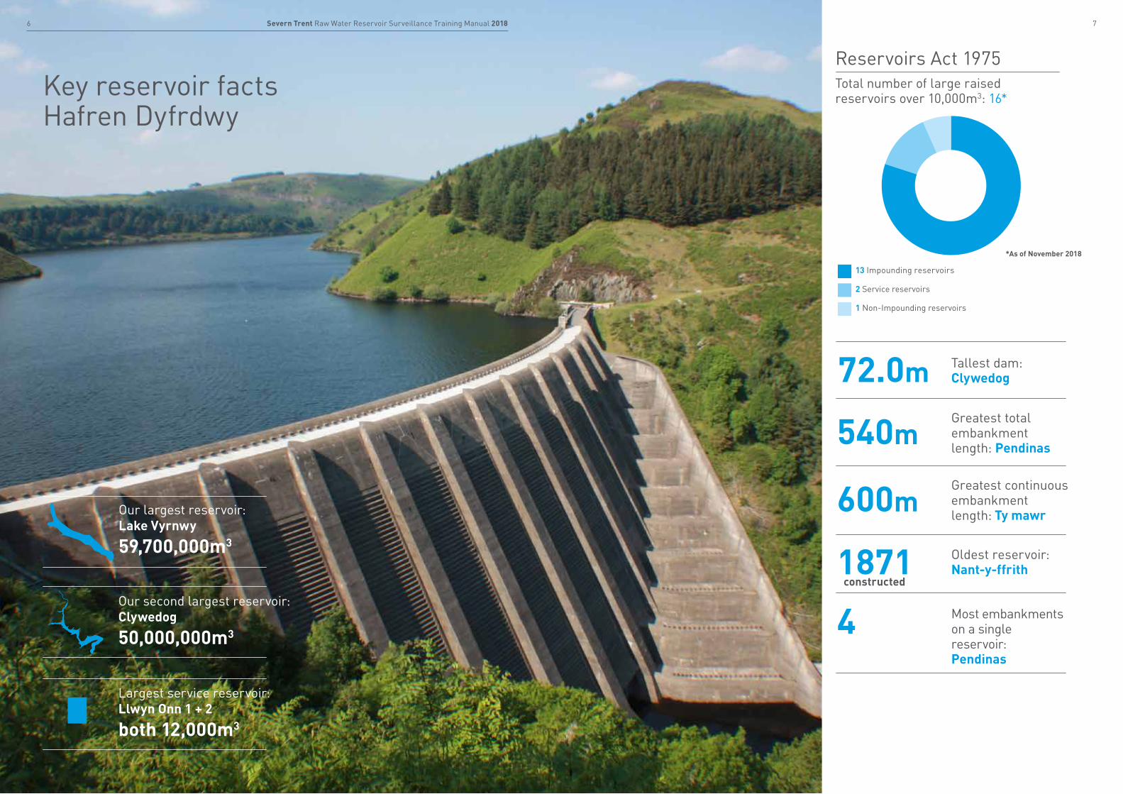
Key reservoir facts Hafren Dyfrdwy
Our largest reservoir:Lake Vyrnwy
59,700,000m3
Our second largest reservoir: Clywedog
50,000,000m3
Largest service reservoir: Llwyn Onn 1 + 2
both 12,000m3
Total number of large raised reservoirs over 10,000m3: 16*
13 Impounding reservoirs
2 Service reservoirs
1 Non-Impounding reservoirs
Reservoirs Act 1975
Tallest dam: Clywedog72.0mGreatest total embankment length: Pendinas
540m
Greatest continuous embankment length: Ty mawr
600m
Oldest reservoir: Nant-y-ffrith1871Most embankments on a single reservoir: Pendinas
4constructed
*As of November 2018
9Severn Trent Raw Water Reservoir Surveillance Training Manual 20188 Severn Trent Raw Water Reservoir Surveillance Training Manual 2018
Chester
Oswestry
Llanfyllin
Wrexham
Llangollen
Vyrnwy
Nant-y-ffrithLlyn Cyfynwy
Pant Glas
Pendinas
PenycaeLower
Ty Mawr
Pen-y-Gwely
PenycaeUpper
Cae Llywyd Marchwiel
Boughton
Llangollen
RIVER SEVERN
RIVE
R DE
E
RIVER TRENT
Stratford-upon-Avon
Cheltenham
Newtown
Redditch
Nuneaton
Evesham
Loughborough
Oswestry Market Drayton
Stafford
Welshpool
Ludlow
Tamworth
Leek
Ashbourne
Rugby
Burtonupon-Trent
Kidderminster
Bridgnorth
Buxton
Scunthorpe
Shipston-on-Stour
Stroud
Great Malvern
Ledbury
CannockLichfield
Hathersage
Llanidloes
Llanfyllin
Bishops Castle
Knighton
Worksop
Newark-on-Trent
Melton Mowbray
MarketHarborough
Stoke-on-Trent
Derby
Matlock Mansfield
Nottingham
Leicester
ShrewsburyTelford
Wolverhampton
Birmingham
Coventry
Warwick
Worcester
Gloucester
Wrexham
Llangollen
Chester
Monmouthshire
RIVE
R DE
E
Bwlch y Gle
Ketley Sands
Middle PoolPriorslee
Holmer Farm
Trimpley
Bartley
Lodge Pool
Willes Meadow Draycote
Stanford
Whitacre
Shustoke Lower
ShustokeUpper
Thornton
CropstonSwithland
Blackbrook
Church Wilne
Tittesworth
Carsington
Ogston
LinacreLower
Ladybower
HowdenDerwent
LinacreUpper
LinacreMiddle
Staunton Harold
Mitcheldean
Frankley
Vyrnwy
Clywedog
Foremark
Esgaireira
Nant yGeifr
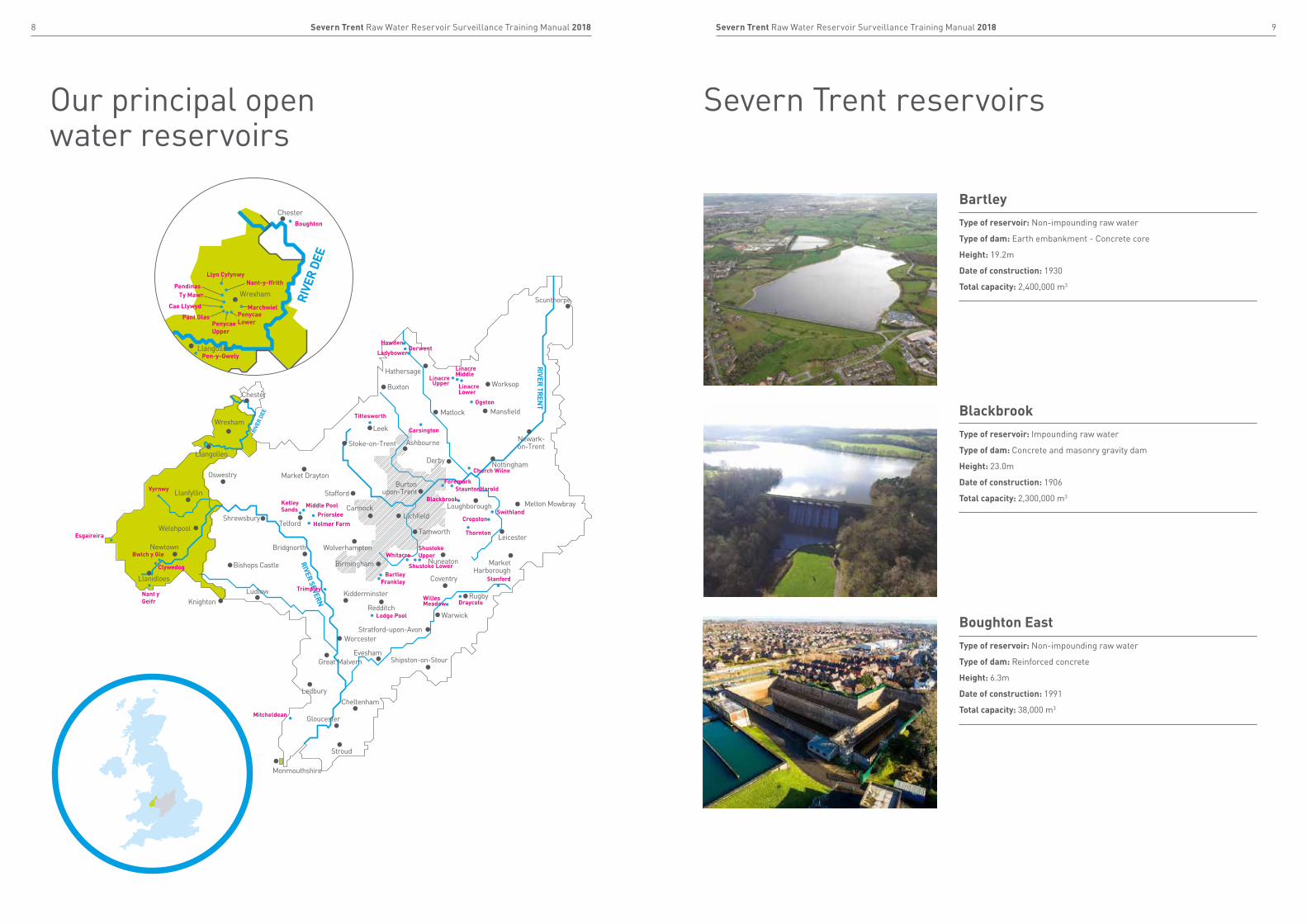
Our principal open water reservoirs
Severn Trent reservoirs
BartleyType of reservoir: Non-impounding raw water
Type of dam: Earth embankment - Concrete core
Height: 19.2m
Date of construction: 1930
Total capacity: 2,400,000 m3
BlackbrookType of reservoir: Impounding raw water
Type of dam: Concrete and masonry gravity dam
Height: 23.0m
Date of construction: 1906
Total capacity: 2,300,000 m3
Boughton EastType of reservoir: Non-impounding raw water
Type of dam: Reinforced concrete
Height: 6.3m
Date of construction: 1991
Total capacity: 38,000 m3
11Severn Trent Raw Water Reservoir Surveillance Training Manual 201810 Severn Trent Raw Water Reservoir Surveillance Training Manual 2018
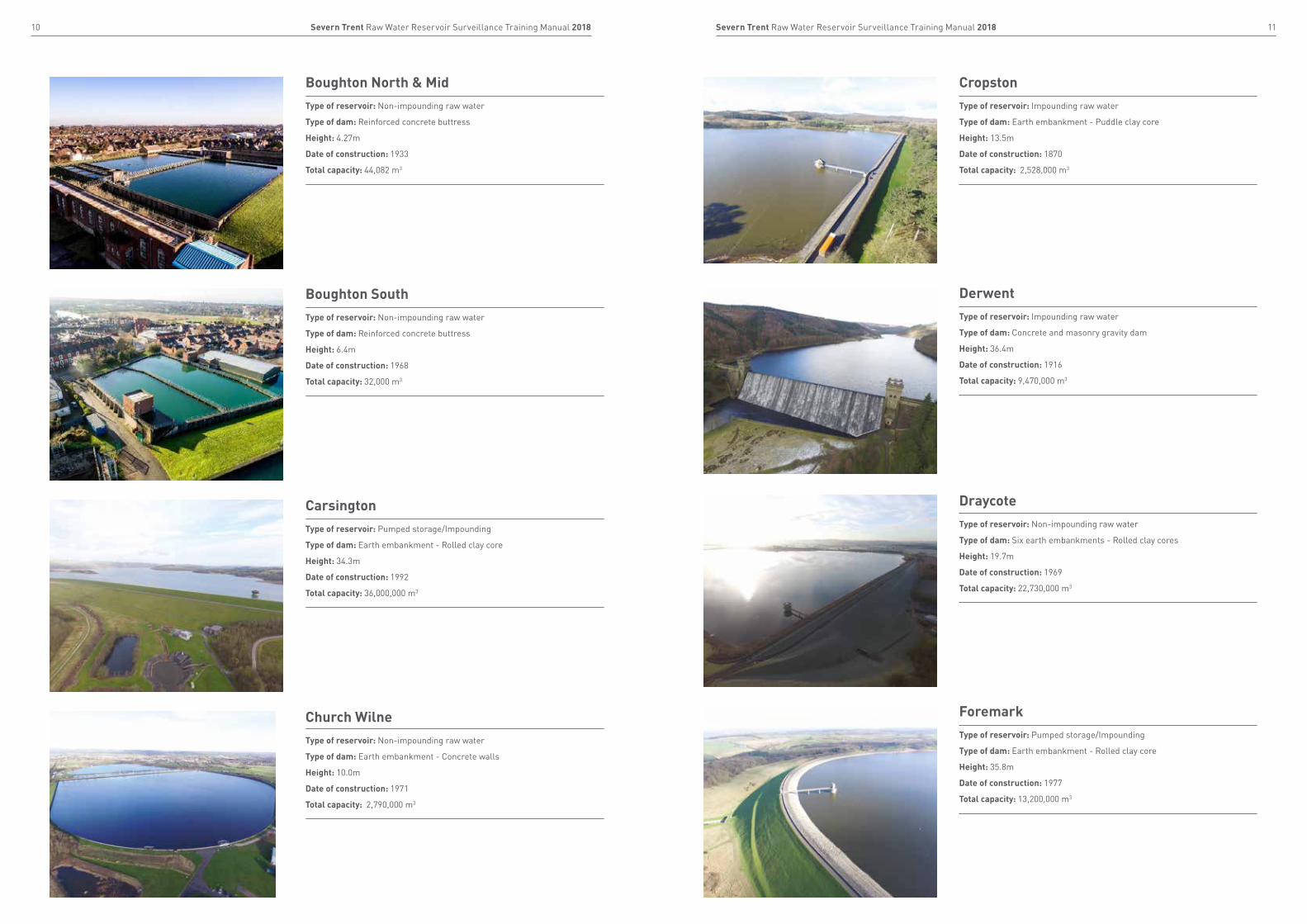
Church WilneType of reservoir: Non-impounding raw water
Type of dam: Earth embankment - Concrete walls
Height: 10.0m
Date of construction: 1971
Total capacity: 2,790,000 m3
CropstonType of reservoir: Impounding raw water
Type of dam: Earth embankment - Puddle clay core
Height: 13.5m
Date of construction: 1870
Total capacity: 2,528,000 m3
DerwentType of reservoir: Impounding raw water
Type of dam: Concrete and masonry gravity dam
Height: 36.4m
Date of construction: 1916
Total capacity: 9,470,000 m3
CarsingtonType of reservoir: Pumped storage/Impounding
Type of dam: Earth embankment - Rolled clay core
Height: 34.3m
Date of construction: 1992
Total capacity: 36,000,000 m3
DraycoteType of reservoir: Non-impounding raw water
Type of dam: Six earth embankments - Rolled clay cores
Height: 19.7m
Date of construction: 1969
Total capacity: 22,730,000 m3
ForemarkType of reservoir: Pumped storage/Impounding
Type of dam: Earth embankment - Rolled clay core
Height: 35.8m
Date of construction: 1977
Total capacity: 13,200,000 m3
Boughton North & MidType of reservoir: Non-impounding raw water
Type of dam: Reinforced concrete buttress
Height: 4.27m
Date of construction: 1933
Total capacity: 44,082 m3
Boughton SouthType of reservoir: Non-impounding raw water
Type of dam: Reinforced concrete buttress
Height: 6.4m
Date of construction: 1968
Total capacity: 32,000 m3
13Severn Trent Raw Water Reservoir Surveillance Training Manual 201812 Severn Trent Raw Water Reservoir Surveillance Training Manual 2018
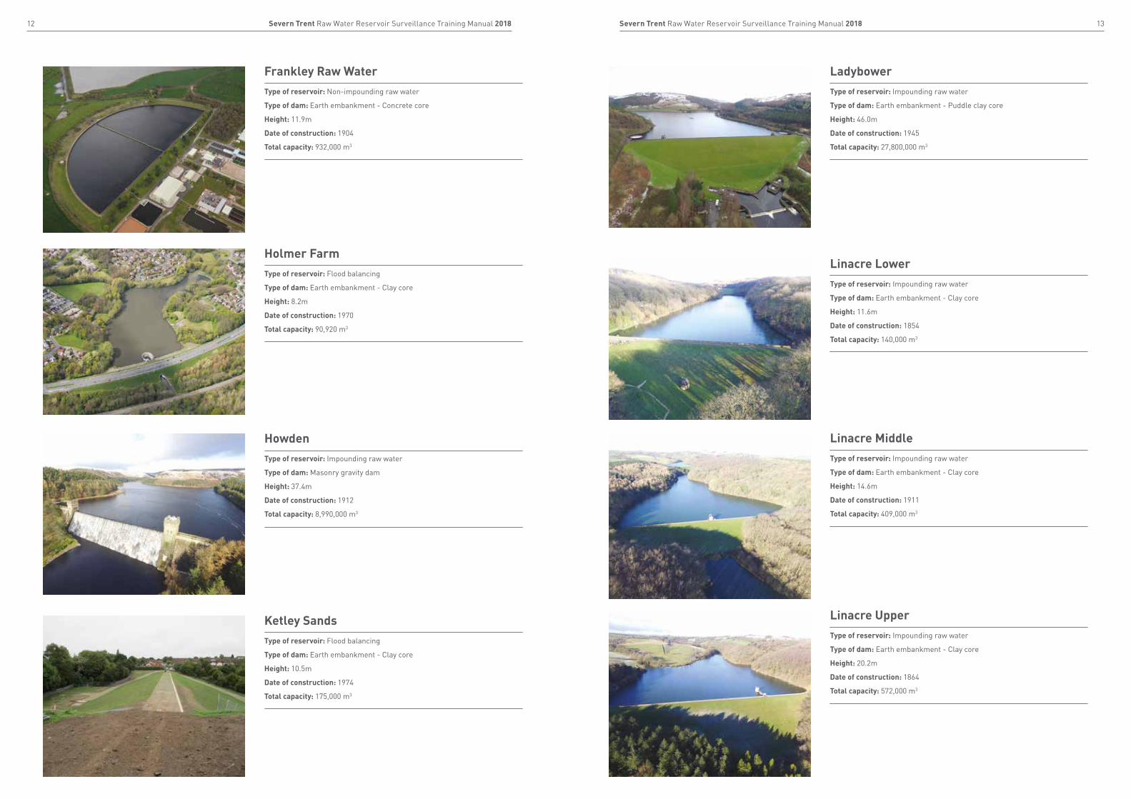
Ketley SandsType of reservoir: Flood balancing
Type of dam: Earth embankment - Clay core
Height: 10.5m
Date of construction: 1974
Total capacity: 175,000 m3
HowdenType of reservoir: Impounding raw water
Type of dam: Masonry gravity dam
Height: 37.4m
Date of construction: 1912
Total capacity: 8,990,000 m3
Frankley Raw WaterType of reservoir: Non-impounding raw water
Type of dam: Earth embankment - Concrete core
Height: 11.9m
Date of construction: 1904
Total capacity: 932,000 m3
Holmer FarmType of reservoir: Flood balancing
Type of dam: Earth embankment - Clay core
Height: 8.2m
Date of construction: 1970
Total capacity: 90,920 m3
Linacre MiddleType of reservoir: Impounding raw water
Type of dam: Earth embankment - Clay core
Height: 14.6m
Date of construction: 1911
Total capacity: 409,000 m3
LadybowerType of reservoir: Impounding raw water
Type of dam: Earth embankment - Puddle clay core
Height: 46.0m
Date of construction: 1945
Total capacity: 27,800,000 m3
Linacre LowerType of reservoir: Impounding raw water
Type of dam: Earth embankment - Clay core
Height: 11.6m
Date of construction: 1854
Total capacity: 140,000 m3
Linacre UpperType of reservoir: Impounding raw water
Type of dam: Earth embankment - Clay core
Height: 20.2m
Date of construction: 1864
Total capacity: 572,000 m3

15Severn Trent Raw Water Reservoir Surveillance Training Manual 201814 Severn Trent Raw Water Reservoir Surveillance Training Manual 2018
Shustoke UpperType of reservoir: Impounding raw water
Type of dam: Earth embankment - Puddle clay core
Height: 6.1m
Date of construction: 1885
Total capacity: 92,000 m3
PriorsleeType of reservoir: Flood balancing reservoir
Type of dam: Earth embankment - Rolled clay core
Height: 10.7m
Date of construction: 1982
Total capacity: 196,000 m3
Shustoke LowerType of reservoir: Non-impounding raw water
Type of dam: Earth embankment - Puddle clay core
Height: 8.4m
Date of construction: 1885
Total capacity: 1,921,000 m3
OgstonType of reservoir: Impounding raw water
Type of dam: Earth embankment - Puddle clay core
Height: 19.8m
Date of construction: 1960
Total capacity: 6,180,000 m3
MitcheldeanType of reservoir: Non-impounding raw water
Type of dam: Reinforced concrete
Height: 6.3m
Date of construction: 1977
Total capacity: 36,400 m3
Middle PoolType of reservoir: Flood balancing
Type of dam: Rockfill embankment - Clay core
Height: 4.9m
Date of construction: 1976
Total capacity: 54,800 m3
Lodge PoolType of reservoir: Flood balancing
Type of dam: Earth embankment
Height: 4.6m
Date of construction: 1969
Total capacity: 23,340 m3
StanfordType of reservoir: Impounding raw water
Type of dam: Earth embankment - Puddle clay core
Height: 8.7m
Date of construction: 1928
Total capacity: 1,527,000 m3
17Severn Trent Raw Water Reservoir Surveillance Training Manual 201816 Severn Trent Raw Water Reservoir Surveillance Training Manual 2018
TrimpleyType of reservoir: Non-impounding raw water
Type of dam: Earth Embankment
Height: 11.9m
Date of construction: 1971
Total capacity: 936,000 m3
WhitacreType of reservoir: Non-impounding raw water
Type of dam: Earth embankment
Height: 5.8m
Date of construction: 1875
Total capacity: 147,000 m3
Willes MeadowType of reservoir: Non-impounding raw water
Type of dam: Earth embankment
Height: 4.1m
Date of construction: 1962
Total capacity: 113,650 m3
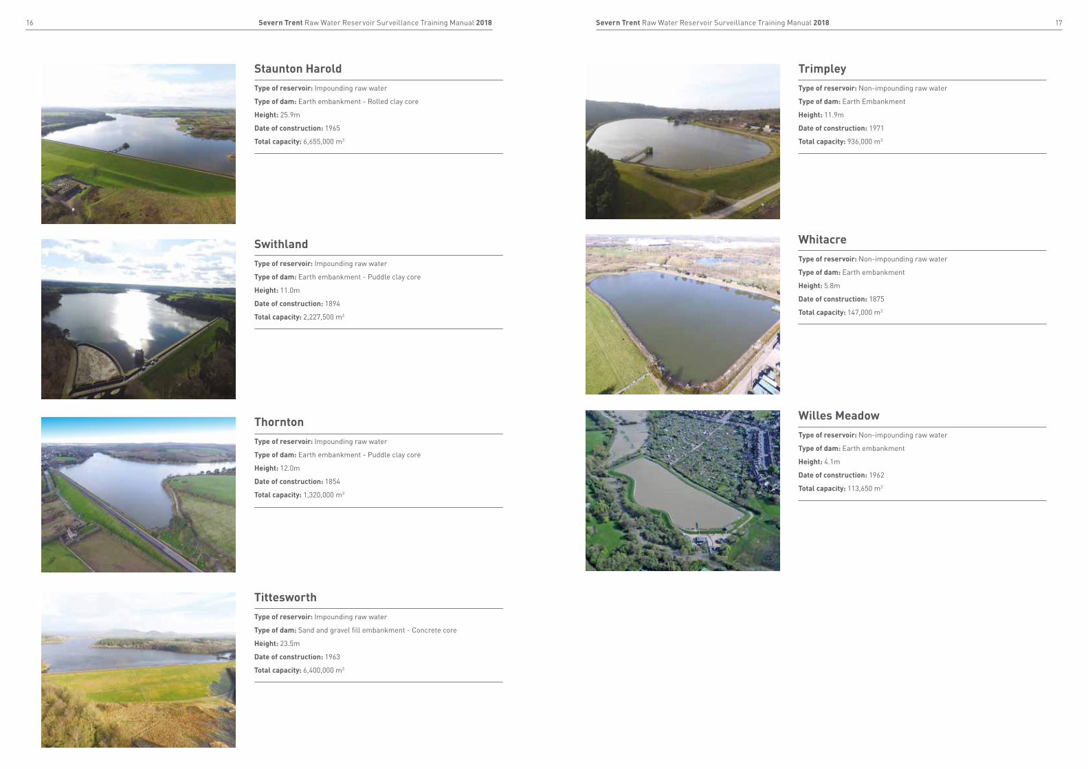
TittesworthType of reservoir: Impounding raw water
Type of dam: Sand and gravel fill embankment - Concrete core
Height: 23.5m
Date of construction: 1963
Total capacity: 6,400,000 m3
ThorntonType of reservoir: Impounding raw water
Type of dam: Earth embankment - Puddle clay core
Height: 12.0m
Date of construction: 1854
Total capacity: 1,320,000 m3
SwithlandType of reservoir: Impounding raw water
Type of dam: Earth embankment - Puddle clay core
Height: 11.0m
Date of construction: 1894
Total capacity: 2,227,500 m3
Staunton HaroldType of reservoir: Impounding raw water
Type of dam: Earth embankment - Rolled clay core
Height: 25.9m
Date of construction: 1965
Total capacity: 6,655,000 m3

19Severn Trent Raw Water Reservoir Surveillance Training Manual 201818 Severn Trent Raw Water Reservoir Surveillance Training Manual 2018
Hafren Dyfrdwy reservoirs
Cae LlwydType of reservoir: Impounding raw water
Type of dam: Earth embankment - puddle clay core
Height: 15m
Date of construction: 1878
Total capacity: 177,000 m3
Bwlch y Gle (Clywedog reservoir saddle dam)Type of reservoir: Impounding raw water
Type of dam: Rock fill embankment - Concrete core
Height: 12.5m
Date of construction: 1967
Total capacity: 50,000,000 m3
Llyn CyfynwyType of reservoir: Impounding raw water
Type of dam: Earth embankment – puddle clay core
Height: 1 and 2 - 2.6m
Date of construction: 1892
Total capacity: 295,000 m3
ClywedogType of reservoir: Impounding raw water
Type of dam: Concrete buttress
Height: 72.0m
Date of construction: 1967
Total capacity: 50,000,000 m3
EsgaireiraType of reservoir: Impounding raw water
Type of dam: Earth embankment - Concrete core
Height: 6m
Date of construction: 1965
Total capacity: c. 20,000
MarchwielType of reservoir: Non-impounding raw water
Type of dam: Earth embankment – 2.5mm HDPE liner
Height: 7.5m
Date of construction: 1981
Total capacity: 139,000 m3
Nant-y-ffrithType of reservoir: Impounding raw water
Type of dam: Earth embankment – puddle clay core
Height: 8.5m
Date of construction: 1871
Total capacity: 103,000 m3
21Severn Trent Raw Water Reservoir Surveillance Training Manual 201820 Severn Trent Raw Water Reservoir Surveillance Training Manual 2018
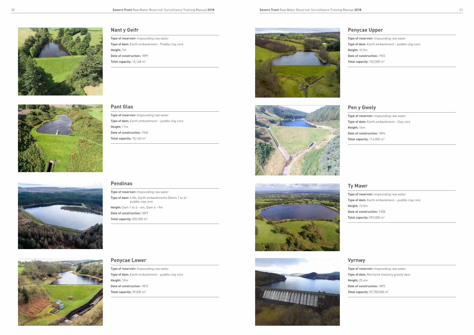
Pant GlasType of reservoir: Impounding raw water
Type of dam: Earth embankment – puddle clay core
Height: 11m
Date of construction: 1940
Total capacity: 18,160 m3
Nant y GeifrType of reservoir: Impounding raw water
Type of dam: Earth embankment - Puddle clay core
Height: 7m
Date of construction: 1899
Total capacity: 15,148 m3
Penycae UpperType of reservoir: Impounding raw water
Type of dam: Earth embankment - puddle clay core
Height: 10.5m
Date of construction: 1902
Total capacity: 102,000 m3
PendinasType of reservoir: Impounding raw water
Type of dam: 4 No. Earth embankments (Dams 1 to 4) - puddle clay core
Height: Dam 1 to 3 – 4m, Dam 4 - 9m
Date of construction: 1897
Total capacity: 282,000 m3
Penycae LowerType of reservoir: Impounding raw water
Type of dam: Earth embankment - puddle clay core
Height: 10m
Date of construction: 1872
Total capacity: 39,000 m3
Pen y GwelyType of reservoir: Impounding raw water
Type of dam: Earth embankment - Clay core
Height: 16m
Date of construction: 1894
Total capacity: 114,000 m3
Ty MawrType of reservoir: Impounding raw water
Type of dam: Earth embankment – puddle clay core
Height: 13.0m
Date of construction: 1908
Total capacity: 593,000 m3
VyrnwyType of reservoir: Impounding raw water
Type of dam: Mortared masonry gravity dam
Height: 25.6m
Date of construction: 1892
Total capacity: 59,700,000 m3
23Severn Trent Raw Water Reservoir Surveillance Training Manual 201822 Severn Trent Raw Water Reservoir Surveillance Training Manual 2018
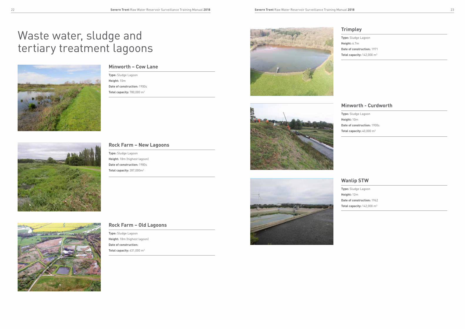
Waste water, sludge and tertiary treatment lagoons
Minworth – Cow LaneType: Sludge Lagoon
Height: 10m
Date of construction: 1900s
Total capacity: 780,000 m3
Rock Farm – New LagoonsType: Sludge Lagoon
Height: 18m (highest lagoon)
Date of construction: 1980s
Total capacity: 287,000m3
Rock Farm – Old LagoonsType: Sludge Lagoon
Height: 18m (highest lagoon)
Date of construction:
Total capacity: 631,000 m3
Wanlip STWType: Sludge Lagoon
Height: 12m
Date of construction: 1962
Total capacity: 142,000 m3
Minworth - CurdworthType: Sludge Lagoon
Height: 10m
Date of construction: 1900s
Total capacity: 40,000 m3
TrimpleyType: Sludge Lagoon
Height: 6.7m
Date of construction: 1971
Total capacity: 142,000 m3
25Severn Trent Raw Water Reservoir Surveillance Training Manual 201824 Severn Trent Raw Water Reservoir Surveillance Training Manual 2018
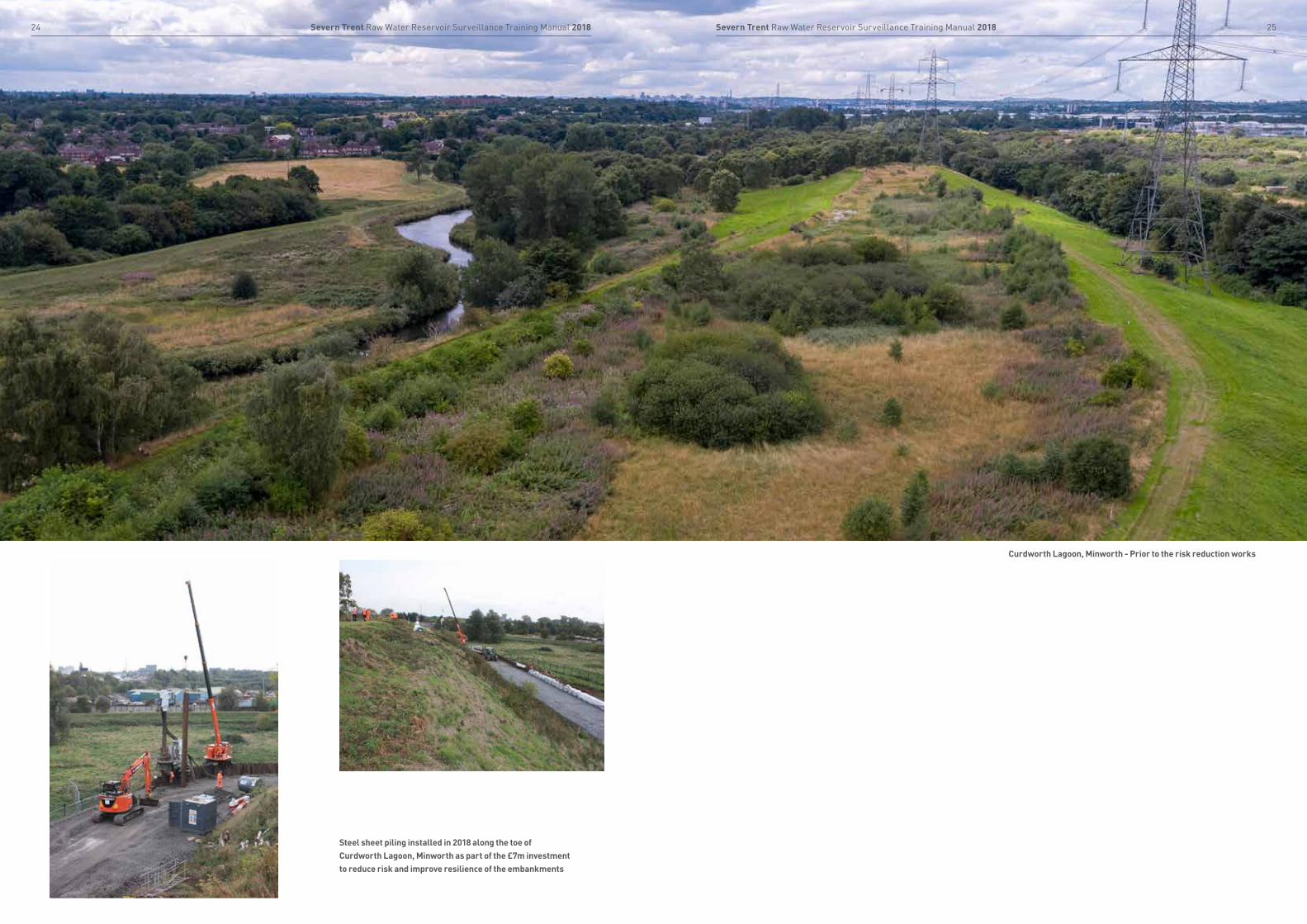
Steel sheet piling installed in 2018 along the toe of Curdworth Lagoon, Minworth as part of the £7m investment to reduce risk and improve resilience of the embankments
Curdworth Lagoon, Minworth - Prior to the risk reduction works

26 Severn Trent Raw Water Reservoir Surveillance Training Manual 2018
1. Introduction 271.1 Background 291.2 Purpose 301.3 Definitions 311.4 Reservoirs and the water cycle 32
2. Purposes of reservoirs 332.1 Raw water reservoirs 352.2 Service reservoirs 352.3 Flood balancing reservoirs 362.4 Waste water lagoons 36
3. Raw water reservoirs: Construction 37
3.1 Types of reservoirs 393.1.1 Impounding reservoirs 393.1.2 Non-impounding reservoirs 393.2 Types of dam 403.2.1 Embankment dams 403.2.2 Gravity dams 42 3.2.3 Buttress dams 433.3 Types of spillway 443.3.1 Embankment dam spillway 443.3.2 Gravity dam spillway 46 3.3.3 Buttress dam spillway 46
4. Raw water reservoirs: Failure 474.1 Reasons for failure 494.1.1 Embankment dams 494.1.2 Gravity and buttress dams 534.2 Consequences of failure 55 Case studies 564.3 Improving our resilience 59
5. Purpose of inspections 615.1 Your role 63
5.2 Structural checks 645.2.1 Dam crest 645.2.2 Upstream face 655.2.3 Downstream face 665.2.4 Mitre 675.2.5 Toe 685.3 Hydrological checks 695.3.1 Overflow and trash screens 695.3.2 Draw down tower, tunnel,
pipes and valves 705.3.3 Instrumentation, drainage
and seepage flows 715.4 Flora 725.5 Animal activity 755.6 Site security 765.7 Reporting 775.7.1 Our reporting structure 78
6. Operating, inspecting and monitoring 79
6.1 Operating protocols 816.2 Inspecting routines 826.3 Monitoring 83
7. Health and safety 877.1 Duty of care 88
8. Legislation 898.1 UK legislation 908.2 Other legislation 91
Contents
1.1 Background 29
1.2 Purpose 30
1.3 Definitions 31
1.4 Reservoirs and the water cycle 32
Section 1Introduction
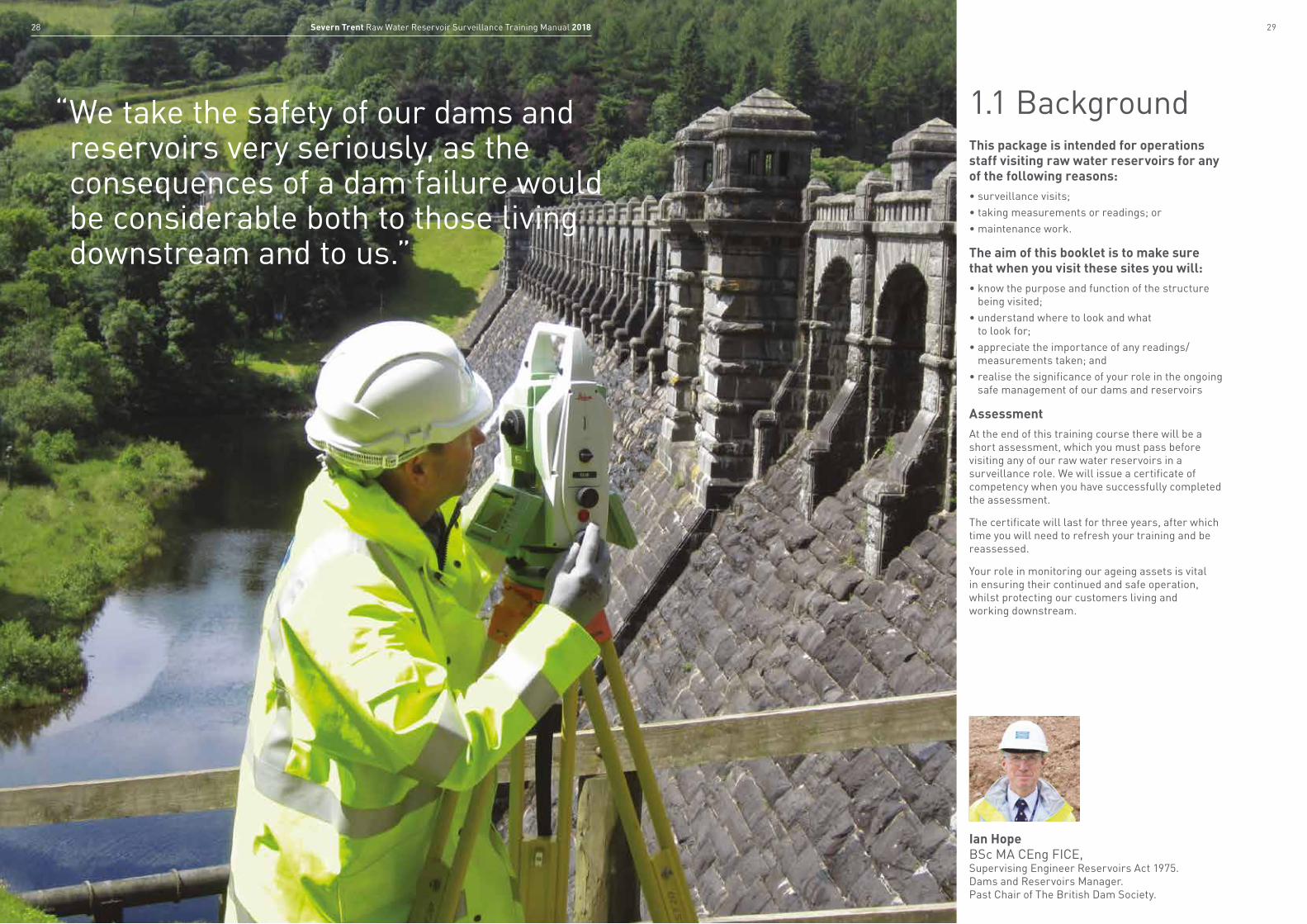
“ We take the safety of our dams and reservoirs very seriously, as the consequences of a dam failure would be considerable both to those living downstream and to us.”
This package is intended for operations staff visiting raw water reservoirs for any of the following reasons:• surveillance visits;• taking measurements or readings; or• maintenance work.
The aim of this booklet is to make sure that when you visit these sites you will:• know the purpose and function of the structure
being visited;• understand where to look and what
to look for; • appreciate the importance of any readings/
measurements taken; and• realise the significance of your role in the ongoing
safe management of our dams and reservoirs
AssessmentAt the end of this training course there will be a short assessment, which you must pass before visiting any of our raw water reservoirs in a surveillance role. We will issue a certificate of competency when you have successfully completed the assessment.
The certificate will last for three years, after which time you will need to refresh your training and be reassessed.
Your role in monitoring our ageing assets is vital in ensuring their continued and safe operation, whilst protecting our customers living and working downstream.
1.1 Background
Ian Hope BSc MA CEng FICE, Supervising Engineer Reservoirs Act 1975. Dams and Reservoirs Manager.Past Chair of The British Dam Society.
2928 Severn Trent Raw Water Reservoir Surveillance Training Manual 2018
31Severn Trent Raw Water Reservoir Surveillance Training Manual 201830 Severn Trent Raw Water Reservoir Surveillance Training Manual 2018
1.2 PurposeWe have produced this booklet, and the accompanying video and presentation, as part of a training package for water treatment works senior technicians and operational staff.
The course gives information and instructions to make visits more effective by explaining:
• where to look;• what to look for; and• why readings/measurements are important in
relation to the condition of the structure.
The course covers:
• the definition of dams, reservoirs and lagoons;• the different types of dams owned by
Severn Trent and Hafren Dyfrdwy;• how raw water reservoirs can fail and therefore,
what to look for when visiting a raw water reservoir.
Before going on any site visit, it is important that you complete a risk assessment in accordance with our health and safety procedures (see section 7 for more details).
Reservoir: A reservoir is a large lake that stores water and can be natural or man-made. Most man-made reservoirs are formed behind dams.
Dam:A dam is a man-made barrier, usually built across a river to hold back water, forming a lake or reservoir behind the dam. It can be constructed from concrete or natural materials such as earth or rock.
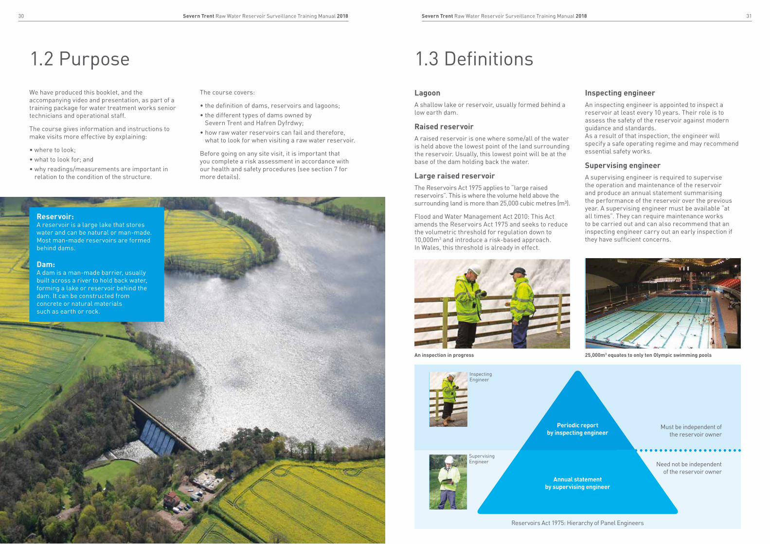
1.3 Definitions
Periodic report by inspecting engineer
Annual report by supervising engineer
Periodic report by inspecting engineer
Annual report by supervising engineer
Must be independent of the reservoir owner
Need not be independent of the reservoir owner
Reservoirs Act 1975: Hierarchy of Panel Engineers
Periodic report by inspecting engineer
Annual statement by supervising engineer
Inspecting Engineer
SupervisingEngineer
25,000m3 equates to only ten Olympic swimming poolsAn inspection in progress
LagoonA shallow lake or reservoir, usually formed behind a low earth dam.
Raised reservoirA raised reservoir is one where some/all of the water is held above the lowest point of the land surrounding the reservoir. Usually, this lowest point will be at the base of the dam holding back the water.
Large raised reservoirThe Reservoirs Act 1975 applies to “large raised reservoirs”. This is where the volume held above the surrounding land is more than 25,000 cubic metres (m³).
Flood and Water Management Act 2010: This Act amends the Reservoirs Act 1975 and seeks to reduce the volumetric threshold for regulation down to 10,000m3 and introduce a risk-based approach. In Wales, this threshold is already in effect.
Inspecting engineerAn inspecting engineer is appointed to inspect a reservoir at least every 10 years. Their role is to assess the safety of the reservoir against modern guidance and standards. As a result of that inspection, the engineer will specify a safe operating regime and may recommend essential safety works.
Supervising engineerA supervising engineer is required to supervise the operation and maintenance of the reservoir and produce an annual statement summarising the performance of the reservoir over the previous year. A supervising engineer must be available “at all times”. They can require maintenance works to be carried out and can also recommend that an inspecting engineer carry out an early inspection if they have sufficient concerns.
33Severn Trent Raw Water Reservoir Surveillance Training Manual 201832 Severn Trent Raw Water Reservoir Surveillance Training Manual 2018
1.4 Reservoirs and the water cycle
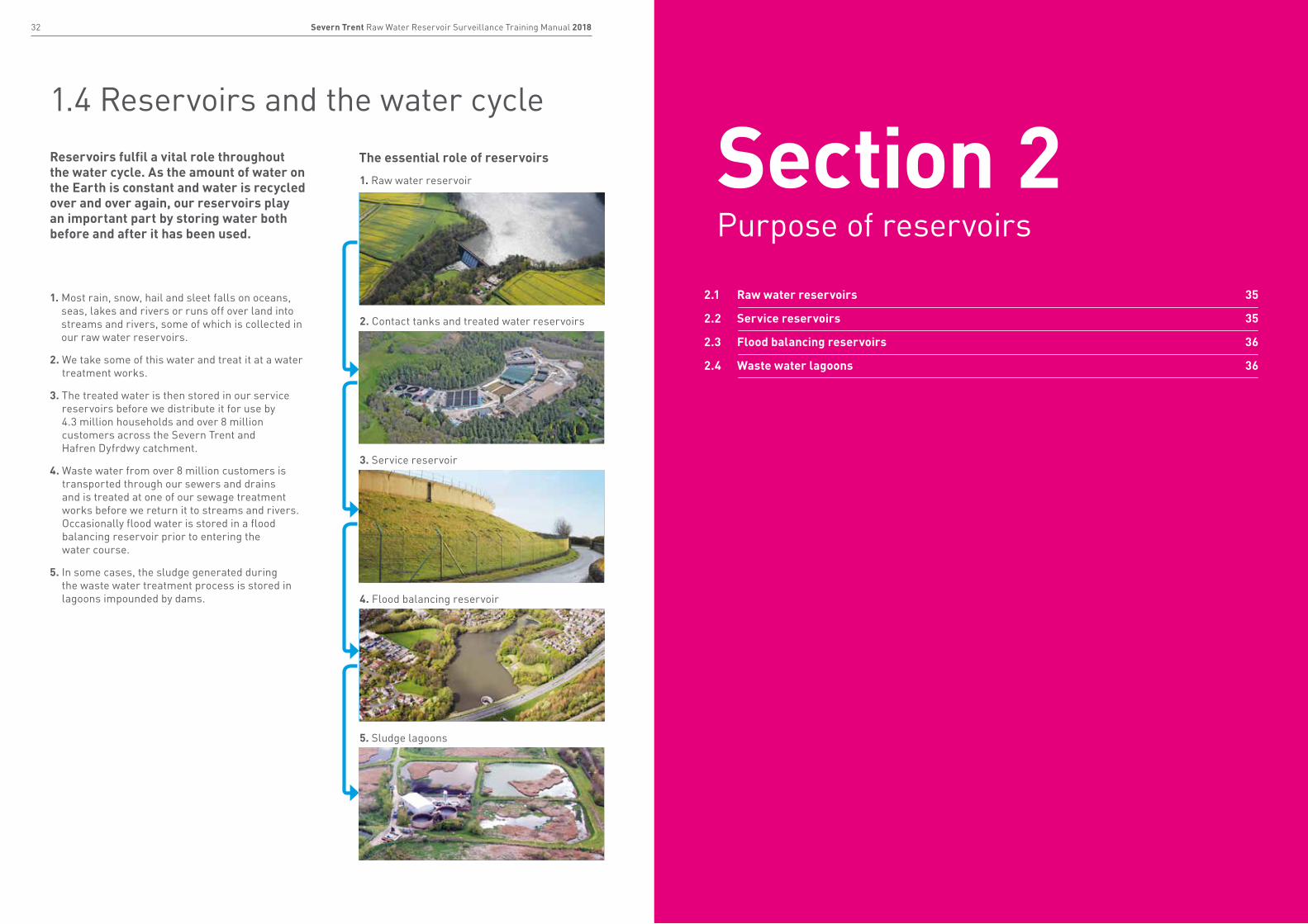
Reservoirs fulfil a vital role throughout the water cycle. As the amount of water on the Earth is constant and water is recycled over and over again, our reservoirs play an important part by storing water both before and after it has been used.
1. Most rain, snow, hail and sleet falls on oceans, seas, lakes and rivers or runs off over land into streams and rivers, some of which is collected in our raw water reservoirs.
2. We take some of this water and treat it at a water treatment works.
3. The treated water is then stored in our service reservoirs before we distribute it for use by 4.3 million households and over 8 million customers across the Severn Trent and Hafren Dyfrdwy catchment.
4. Waste water from over 8 million customers is transported through our sewers and drains and is treated at one of our sewage treatment works before we return it to streams and rivers. Occasionally flood water is stored in a flood balancing reservoir prior to entering the water course.
5. In some cases, the sludge generated during the waste water treatment process is stored in lagoons impounded by dams.
1. Raw water reservoir
2. Contact tanks and treated water reservoirs
3. Service reservoir
4. Flood balancing reservoir
5. Sludge lagoons
The essential role of reservoirs
2.1 Raw water reservoirs 35
2.2 Service reservoirs 35
2.3 Flood balancing reservoirs 36
2.4 Waste water lagoons 36
Section 2Purpose of reservoirs
35Severn Trent Raw Water Reservoir Surveillance Training Manual 201834 Severn Trent Raw Water Reservoir Surveillance Training Manual 2018
2.1 Raw water reservoirs
2.2 Service reservoirs
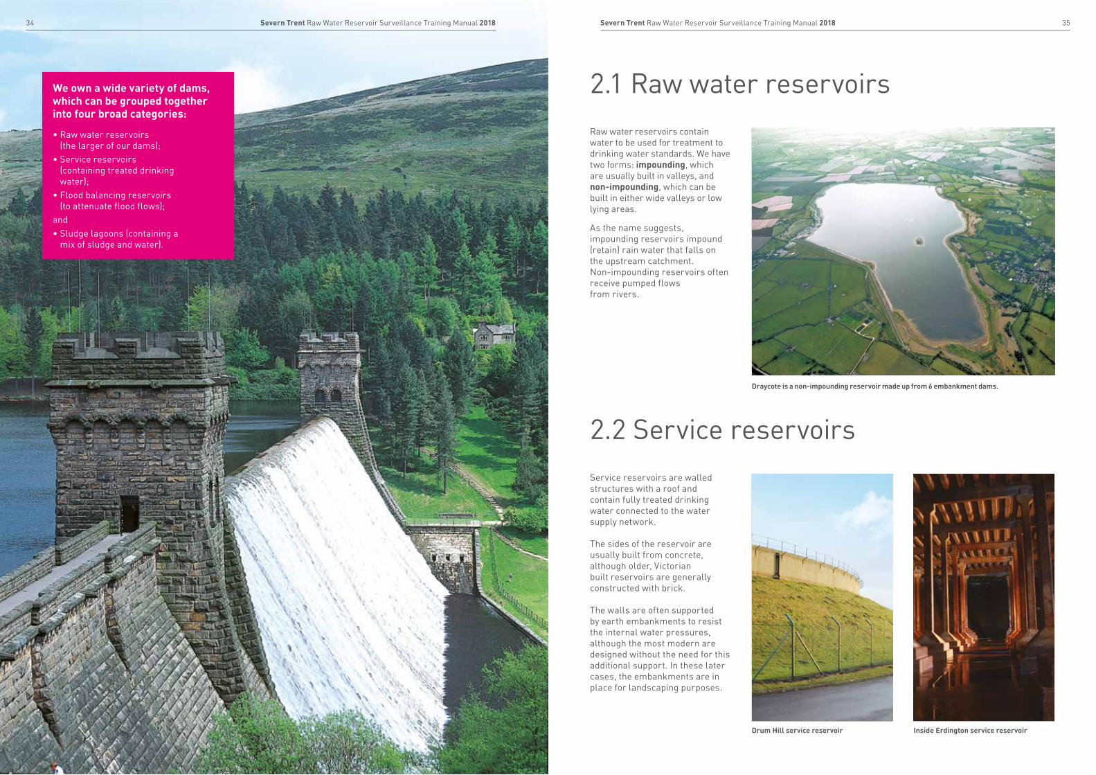
Raw water reservoirs contain water to be used for treatment to drinking water standards. We have two forms: impounding, which are usually built in valleys, and non-impounding, which can be built in either wide valleys or low lying areas.
As the name suggests, impounding reservoirs impound (retain) rain water that falls on the upstream catchment. Non-impounding reservoirs often receive pumped flows from rivers.
Service reservoirs are walled structures with a roof and contain fully treated drinking water connected to the water supply network. The sides of the reservoir are usually built from concrete, although older, Victorian built reservoirs are generally constructed with brick. The walls are often supported by earth embankments to resist the internal water pressures, although the most modern are designed without the need for this additional support. In these later cases, the embankments are in place for landscaping purposes.
Draycote is a non-impounding reservoir made up from 6 embankment dams.
Drum Hill service reservoir Inside Erdington service reservoir
We own a wide variety of dams, which can be grouped together into four broad categories:
• Raw water reservoirs (the larger of our dams);
• Service reservoirs (containing treated drinking water);
• Flood balancing reservoirs (to attenuate flood flows);
and• Sludge lagoons (containing a
mix of sludge and water).
37Severn Trent Raw Water Reservoir Surveillance Training Manual 201836 Severn Trent Raw Water Reservoir Surveillance Training Manual 2018
2.3 Flood balancing reservoirs
2.4 Waste water lagoons
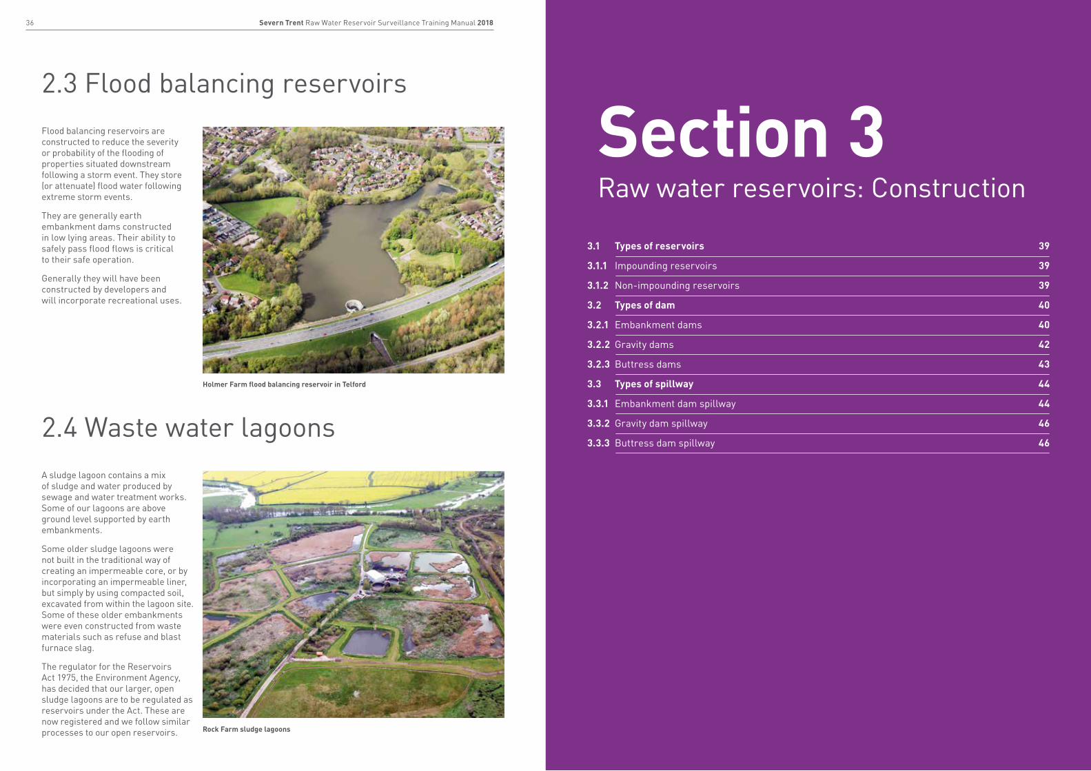
Flood balancing reservoirs are constructed to reduce the severity or probability of the flooding of properties situated downstream following a storm event. They store (or attenuate) flood water following extreme storm events.
They are generally earth embankment dams constructed in low lying areas. Their ability to safely pass flood flows is critical to their safe operation.
Generally they will have been constructed by developers and will incorporate recreational uses.
A sludge lagoon contains a mix of sludge and water produced by sewage and water treatment works. Some of our lagoons are above ground level supported by earth embankments.
Some older sludge lagoons were not built in the traditional way of creating an impermeable core, or by incorporating an impermeable liner, but simply by using compacted soil, excavated from within the lagoon site. Some of these older embankments were even constructed from waste materials such as refuse and blast furnace slag.
The regulator for the Reservoirs Act 1975, the Environment Agency, has decided that our larger, open sludge lagoons are to be regulated as reservoirs under the Act. These are now registered and we follow similar processes to our open reservoirs.
Holmer Farm flood balancing reservoir in Telford
Rock Farm sludge lagoons
3.1 Types of reservoirs 39
3.1.1 Impounding reservoirs 39
3.1.2 Non-impounding reservoirs 39
3.2 Types of dam 40
3.2.1 Embankment dams 40
3.2.2 Gravity dams 42
3.2.3 Buttress dams 43
3.3 Types of spillway 44
3.3.1 Embankment dam spillway 44
3.3.2 Gravity dam spillway 46
3.3.3 Buttress dam spillway 46
Section 3Raw water reservoirs: Construction
39Severn Trent Raw Water Reservoir Surveillance Training Manual 201838 Severn Trent Raw Water Reservoir Surveillance Training Manual 2018
3.1 Types of reservoirs
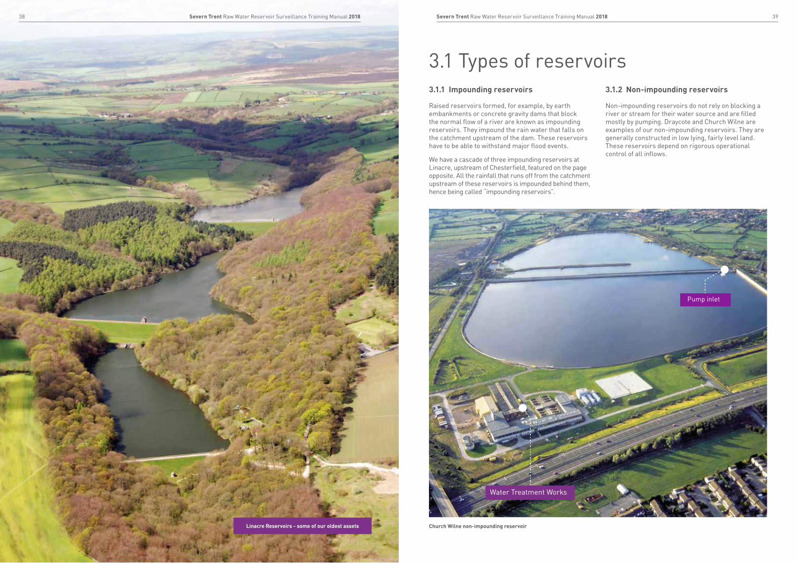
Raised reservoirs formed, for example, by earth embankments or concrete gravity dams that block the normal flow of a river are known as impounding reservoirs. They impound the rain water that falls on the catchment upstream of the dam. These reservoirs have to be able to withstand major flood events.
We have a cascade of three impounding reservoirs at Linacre, upstream of Chesterfield, featured on the page opposite. All the rainfall that runs off from the catchment upstream of these reservoirs is impounded behind them, hence being called “impounding reservoirs”.
Non-impounding reservoirs do not rely on blocking a river or stream for their water source and are filled mostly by pumping. Draycote and Church Wilne are examples of our non-impounding reservoirs. They are generally constructed in low lying, fairly level land. These reservoirs depend on rigorous operational control of all inflows.
Church Wilne non-impounding reservoirLinacre Reservoirs - some of our oldest assets
3.1.1 Impounding reservoirs 3.1.2 Non-impounding reservoirs
Pump inlet
Water Treatment Works
40 Severn Trent Raw Water Reservoir Surveillance Training Manual 2018 41Severn Trent Raw Water Reservoir Surveillance Training Manual 2018
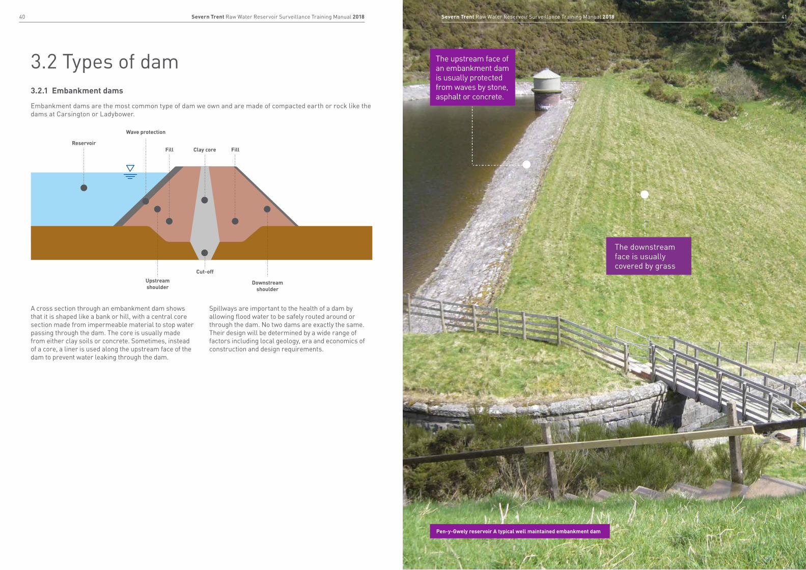
3.2 Types of dam
Embankment dams are the most common type of dam we own and are made of compacted earth or rock like the dams at Carsington or Ladybower.
A cross section through an embankment dam shows that it is shaped like a bank or hill, with a central core section made from impermeable material to stop water passing through the dam. The core is usually made from either clay soils or concrete. Sometimes, instead of a core, a liner is used along the upstream face of the dam to prevent water leaking through the dam.
Spillways are important to the health of a dam by allowing flood water to be safely routed around or through the dam. No two dams are exactly the same. Their design will be determined by a wide range of factors including local geology, era and economics of construction and design requirements.
3.2.1 Embankment dams
Reservoir
Wave protection
Downstream shoulder
Cut-off
Fill Clay core Fill
Upstream shoulder
The upstream face of an embankment dam is usually protected from waves by stone, asphalt or concrete.
The downstream face is usually covered by grass
Pen-y-Gwely reservoir A typical well maintained embankment dam
43Severn Trent Raw Water Reservoir Surveillance Training Manual 201842 Severn Trent Raw Water Reservoir Surveillance Training Manual 2018
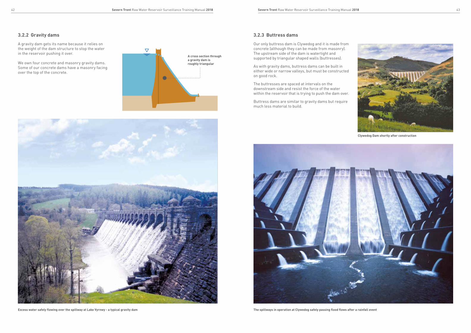
A gravity dam gets its name because it relies on the weight of the dam structure to stop the water in the reservoir pushing it over. We own four concrete and masonry gravity dams. Some of our concrete dams have a masonry facing over the top of the concrete.
Our only buttress dam is Clywedog and it is made from concrete (although they can be made from masonry). The upstream side of the dam is watertight and supported by triangular shaped walls (buttresses).
As with gravity dams, buttress dams can be built in either wide or narrow valleys, but must be constructed on good rock.
The buttresses are spaced at intervals on the downstream side and resist the force of the water within the reservoir that is trying to push the dam over.
Buttress dams are similar to gravity dams but require much less material to build.
3.2.2 Gravity dams 3.2.3 Buttress dams
A cross section through a gravity dam is roughly triangular
Excess water safely flowing over the spillway at Lake Vyrnwy - a typical gravity dam The spillways in operation at Clywedog safely passing flood flows after a rainfall event
Clywedog Dam shortly after construction

45Severn Trent Raw Water Reservoir Surveillance Training Manual 201844 Severn Trent Raw Water Reservoir Surveillance Training Manual 2018
3.3 Types of spillway3.3.1 Embankment dam spillway
Open channel spillway
As flood water cannot generally be allowed to flow over an embankment dam crest, an open channel spillway is constructed to safely manage all flood flows. This is usually located slightly upstream and to the side of the dam crest. It can be constructed over the crest and downstream face if specifically designed to do so. The spillway is usually constructed of concrete but may, in some cases on older reservoirs, be masonry.
Drop shaft or “morning glory” spillway
A drop shaft spillway consists of an overflow weir, which surplus water in the reservoir passes over and drops down a vertical shaft, before flowing through a horizontal tunnel into the downstream river channel. If the inlet to the shaft is funnel shaped, it is referred to as a Morning Glory spillway.
As with overflow spillways, it is also possible for drop shaft spillways to fail to function as designed, particularly because of blockages.
This training booklet covers the types of spillway used on Severn Trent and Hafern Dyfrdwy reservoirs. Other types of spillway include: fuse plug, tipping gates, siphons, wedge blocks and baffle block spillways.
Blockages
If the spillway becomes blocked by rubbish, for example, water levels within the reservoir can rise, leading to water flowing over the top of the dam, weakening the dam itself. This is explained in more detail in Section 5.3.
Out of channel flow
If the spillway is too small for the volume of water flowing down it, the material outside the spillway walls can erode, resulting in a lack of support for the spillway walls. If the erosion continues, the sheer weight of the material in the dam can cause the dam itself to slump, leaving a low area on the dam crest that would be vulnerable during storm events. This is explained in Section 4.1.1.
Poor masonry condition
Some of the masonry structures that were built with lime mortar in the 19th century can be weakened after being exposed to seeping water over long periods, leading to the collapse of the spillway. Ice, rocks and logs can all erode the concrete and masonry surfaces of spillways.
Constant cycles of either freezing and thawing, wetting and drying or heating and cooling can cause surfaces to disintegrate, weakening the structure.
The drop shaft spillway at Ladybower Reservoir is pictured; both dry and spilling
Stanford Reservoir with spillway in operation
Boltby Reservoir, Yorkshire, in 2005 during and immediately after a major storm event. The masonry spillway protecting the dam failed as illustrated.
It is possible for open channel spillways to fail for a number of different reasons, including:
Spillways safely manage excess flood flows and must be kept clear, fully operational and in good order
Stanford Reservoir was also built with a bywash channel which feeds into the spillway, allowing flow to be diverted around the reservoir.
Overflow weir
The upstream face of dam
Spillway
47Severn Trent Raw Water Reservoir Surveillance Training Manual 201846 Severn Trent Raw Water Reservoir Surveillance Training Manual 2018
4.1 Reasons for failure 49
4.1.1 Embankment dams 49
4.1.2 Gravity and buttress dams 53
4.2 Consequences of failure 55
Case studies 56
4.3 Improving our resilience 59
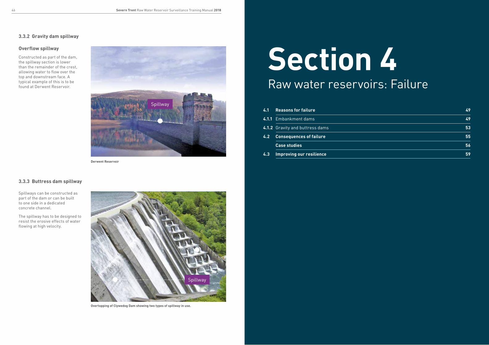
Overflow spillway
Constructed as part of the dam, the spillway section is lower than the remainder of the crest, allowing water to flow over the top and downstream face. A typical example of this is to be found at Derwent Reservoir.
Spillways can be constructed as part of the dam or can be built to one side in a dedicated concrete channel.
The spillway has to be designed to resist the erosive effects of water flowing at high velocity.
Derwent Reservoir
3.3.2 Gravity dam spillway
3.3.3 Buttress dam spillway
Overtopping of Clywedog Dam showing two types of spillway in use.
Spillway
Spillway
Section 4Raw water reservoirs: Failure
49Severn Trent Raw Water Reservoir Surveillance Training Manual 201848 Severn Trent Raw Water Reservoir Surveillance Training Manual 2018
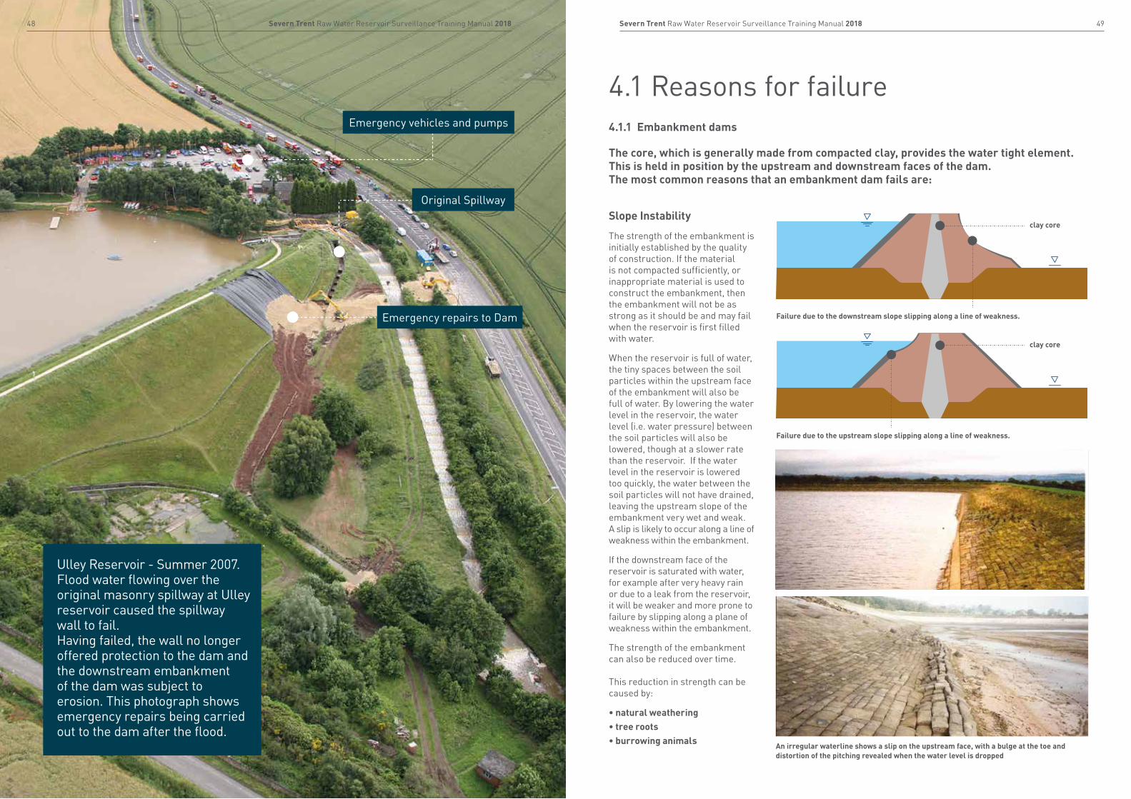
Ulley Reservoir - Summer 2007. Flood water flowing over the original masonry spillway at Ulley reservoir caused the spillway wall to fail. Having failed, the wall no longer offered protection to the dam and the downstream embankment of the dam was subject to erosion. This photograph shows emergency repairs being carried out to the dam after the flood.
Emergency repairs to Dam
Emergency vehicles and pumps
Original Spillway
4.1 Reasons for failure4.1.1 Embankment dams
The core, which is generally made from compacted clay, provides the water tight element. This is held in position by the upstream and downstream faces of the dam. The most common reasons that an embankment dam fails are:
Slope Instability
The strength of the embankment is initially established by the quality of construction. If the material is not compacted sufficiently, or inappropriate material is used to construct the embankment, then the embankment will not be as strong as it should be and may fail when the reservoir is first filled with water.
When the reservoir is full of water, the tiny spaces between the soil particles within the upstream face of the embankment will also be full of water. By lowering the water level in the reservoir, the water level (i.e. water pressure) between the soil particles will also be lowered, though at a slower rate than the reservoir. If the water level in the reservoir is lowered too quickly, the water between the soil particles will not have drained, leaving the upstream slope of the embankment very wet and weak. A slip is likely to occur along a line of weakness within the embankment.
If the downstream face of the reservoir is saturated with water, for example after very heavy rain or due to a leak from the reservoir, it will be weaker and more prone to failure by slipping along a plane of weakness within the embankment.
The strength of the embankment can also be reduced over time. This reduction in strength can be caused by:
• natural weathering• tree roots• burrowing animals
clay core
clay core
Failure due to the downstream slope slipping along a line of weakness.
Failure due to the upstream slope slipping along a line of weakness.
An irregular waterline shows a slip on the upstream face, with a bulge at the toe and distortion of the pitching revealed when the water level is dropped
51Severn Trent Raw Water Reservoir Surveillance Training Manual 201850 Severn Trent Raw Water Reservoir Surveillance Training Manual 2018
Analogy of embankment failure. The photos illustrate how an embankment can fail on a worked example:
Evidence of internal erosion may not be as obvious as a major hole but as a depression as indicated by the manhole key which has been placed in the hole.
1. Embankment retaining water 2. Overfilling of reservoir 3. As water overflows, the embankment erodes away
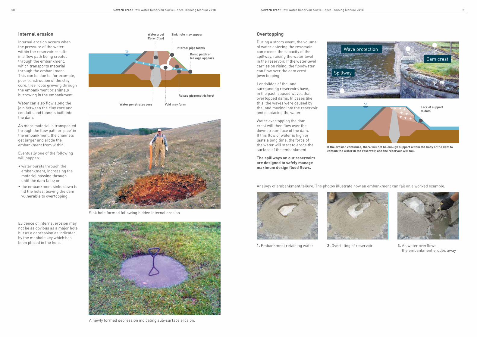
Internal erosion occurs when the pressure of the water within the reservoir results in a flow path being created through the embankment, which transports material through the embankment. This can be due to, for example, poor construction of the clay core, tree roots growing through the embankment or animals burrowing in the embankment.
Water can also flow along the join between the clay core and conduits and tunnels built into the dam.
As more material is transported through the flow path or ‘pipe’ in the embankment, the channels get larger and erode the embankment from within.
Eventually one of the following will happen:
• water bursts through the embankment, increasing the material passing through until the dam fails; or
• the embankment sinks down to fill the holes, leaving the dam vulnerable to overtopping.
Internal erosion
During a storm event, the volume of water entering the reservoir can exceed the capacity of the spillway, raising the water level in the reservoir. If the water level carries on rising, the floodwater can flow over the dam crest (overtopping).
Landslides of the land surrounding reservoirs have, in the past, caused waves that overtopped dams. In cases like this, the waves were caused by the land moving into the reservoir and displacing the water.
Water overtopping the dam crest will then flow over the downstream face of the dam. If this flow of water is high or lasts a long time, the force of the water will start to erode the surface of the embankment.
The spillways on our reservoirs are designed to safely manage maximum design flood flows.
OvertoppingWaterproof Core (Clay)
Sink hole may appear
Internal pipe forms
Damp patch or leakage appears
Lack of support to dam
Raised piezometric level
Void may formWater penetrates core
A newly formed depression indicating sub-surface erosion.
Sink hole formed following hidden internal erosion
Wave protection
Spillway
Dam crest
If the erosion continues, there will not be enough support within the body of the dam to contain the water in the reservoir, and the reservoir will fail.
53Severn Trent Raw Water Reservoir Surveillance Training Manual 201852 Severn Trent Raw Water Reservoir Surveillance Training Manual 2018
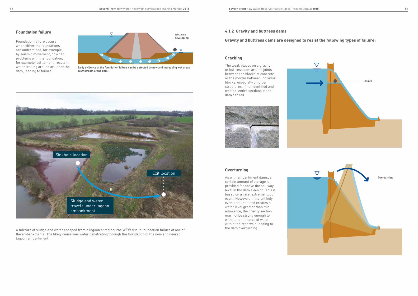
Foundation failure occurs when either the foundations are undermined, for example, by seismic movement, or when problems with the foundation, for example, settlement, result in water leaking around or under the dam, leading to failure.
Foundation failureWet area developing
Early evidence of the foundation failure can be detected by new and increasing wet areas downstream of the dam.
Sludge and water travels under lagoon embankment
Exit location
A mixture of sludge and water escaped from a lagoon at Melbourne WTW due to foundation failure of one of the embankments. The likely cause was water penetrating through the foundation of the non-engineered lagoon embankment.
Cracking
The weak places on a gravity or buttress dam are the joints between the blocks of concrete or the mortar between individual blocks, especially on older structures. If not identified and treated, entire sections of the dam can fail.
Overturning
As with embankment dams, a certain amount of storage is provided for above the spillway level in the dam’s design. This is based on a rare, extreme flood event. However, in the unlikely event that the flood creates a water level greater than this allowance, the gravity section may not be strong enough to withstand the force of water within the reservoir, leading to the dam overturning.
4.1.2 Gravity and buttress dams
Gravity and buttress dams are designed to resist the following types of failure:
➔
➔
Joints
Overturning
Sinkhole location
55Severn Trent Raw Water Reservoir Surveillance Training Manual 201854 Severn Trent Raw Water Reservoir Surveillance Training Manual 2018
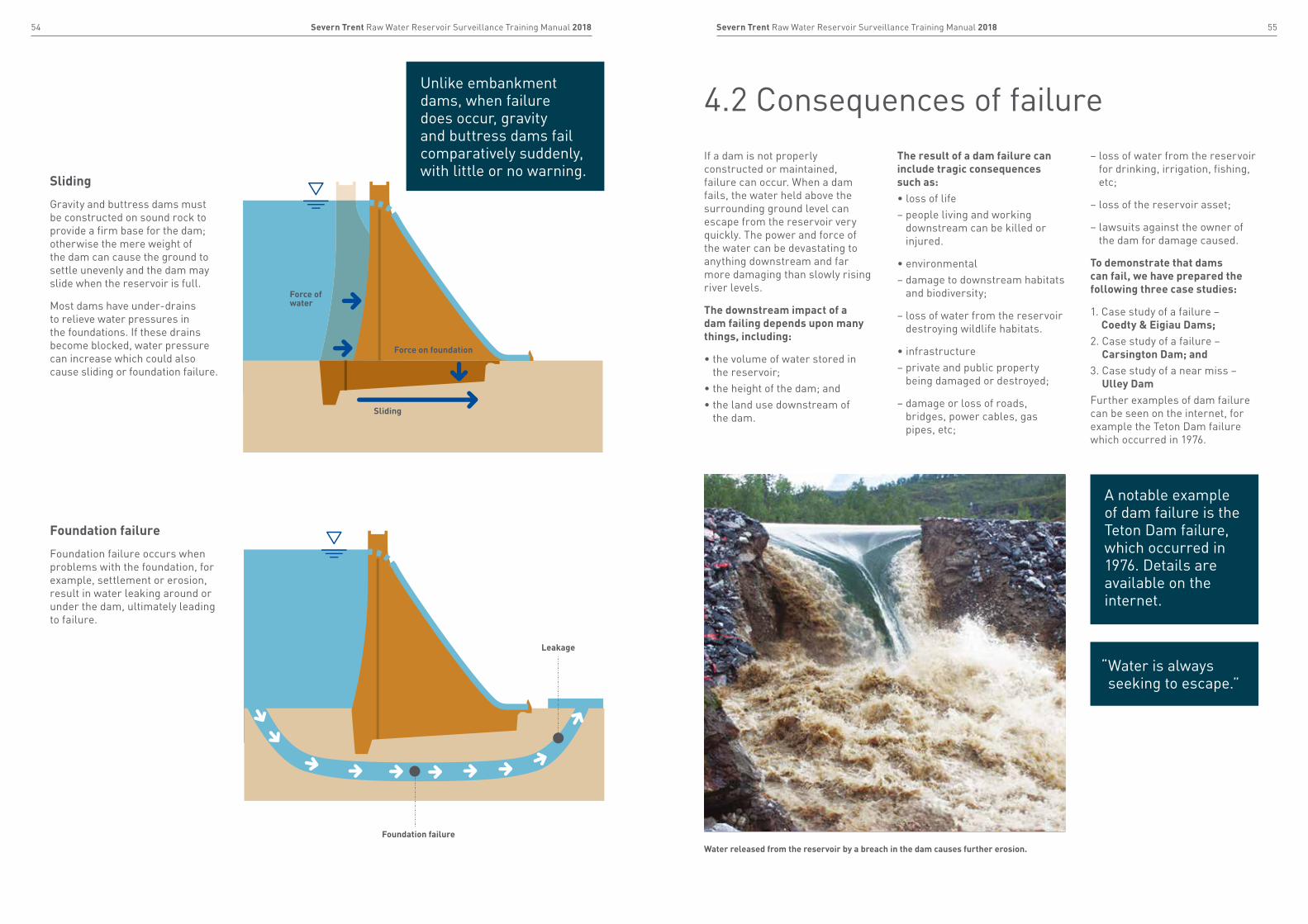
Sliding
Gravity and buttress dams must be constructed on sound rock to provide a firm base for the dam; otherwise the mere weight of the dam can cause the ground to settle unevenly and the dam may slide when the reservoir is full.
Most dams have under-drains to relieve water pressures in the foundations. If these drains become blocked, water pressure can increase which could also cause sliding or foundation failure.
Foundation failure
Foundation failure occurs when problems with the foundation, for example, settlement or erosion, result in water leaking around or under the dam, ultimately leading to failure.
Foundation failure
Leakage
Force of water
Force on foundation
Sliding
Unlike embankment dams, when failure does occur, gravity and buttress dams fail comparatively suddenly, with little or no warning.
If a dam is not properly constructed or maintained, failure can occur. When a dam fails, the water held above the surrounding ground level can escape from the reservoir very quickly. The power and force of the water can be devastating to anything downstream and far more damaging than slowly rising river levels.
The downstream impact of a dam failing depends upon many things, including:
• the volume of water stored in the reservoir;
• the height of the dam; and• the land use downstream of
the dam.
The result of a dam failure can include tragic consequences such as:• loss of life– people living and working
downstream can be killed or injured.
• environmental– damage to downstream habitats
and biodiversity;
– loss of water from the reservoir destroying wildlife habitats.
• infrastructure– private and public property
being damaged or destroyed;
– damage or loss of roads, bridges, power cables, gas pipes, etc;
– loss of water from the reservoir for drinking, irrigation, fishing, etc;
– loss of the reservoir asset;
– lawsuits against the owner of the dam for damage caused.
To demonstrate that dams can fail, we have prepared the following three case studies:
1. Case study of a failure – Coedty & Eigiau Dams;
2. Case study of a failure – Carsington Dam; and
3. Case study of a near miss – Ulley Dam
Further examples of dam failure can be seen on the internet, for example the Teton Dam failure which occurred in 1976.
Water released from the reservoir by a breach in the dam causes further erosion.
4.2 Consequences of failure
A notable example of dam failure is the Teton Dam failure, which occurred in 1976. Details are available on the internet.
“ Water is always seeking to escape.”
57Severn Trent Raw Water Reservoir Surveillance Training Manual 201856 Severn Trent Raw Water Reservoir Surveillance Training Manual 2018
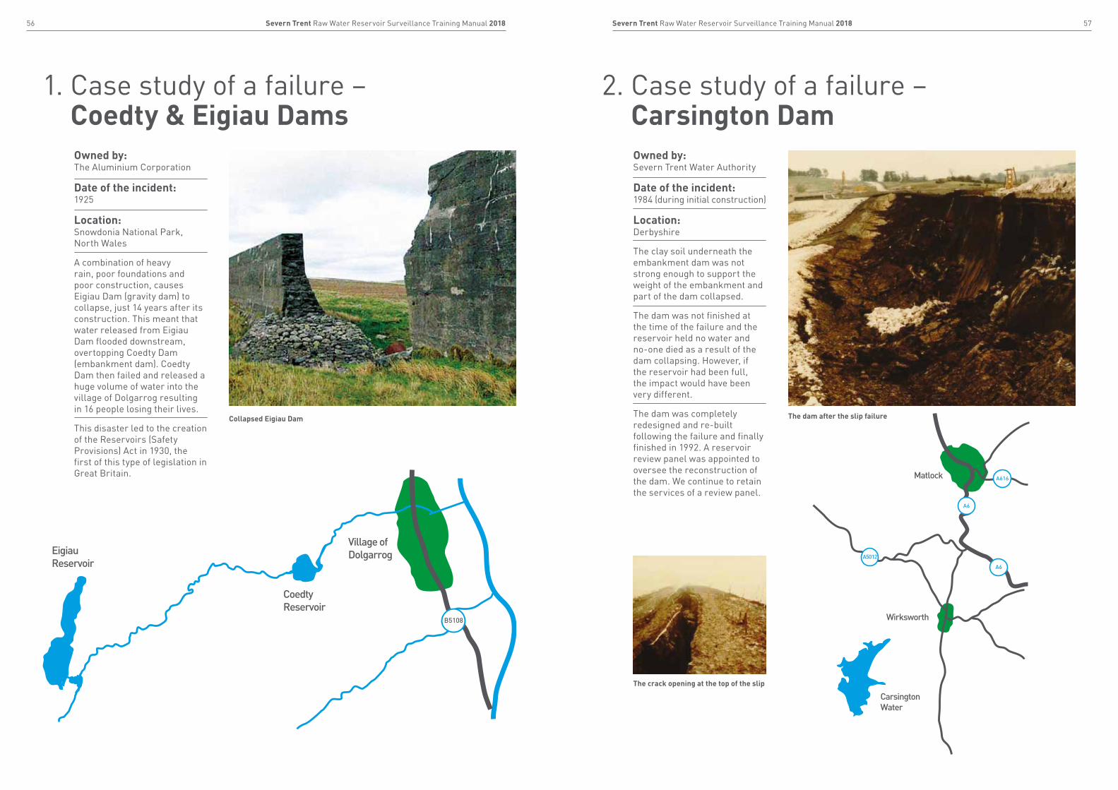
Owned by:Severn Trent Water Authority
Date of the incident:1984 (during initial construction)
Location: Derbyshire
The clay soil underneath the embankment dam was not strong enough to support the weight of the embankment and part of the dam collapsed.
The dam was not finished at the time of the failure and the reservoir held no water and no-one died as a result of the dam collapsing. However, if the reservoir had been full, the impact would have been very different.
The dam was completely redesigned and re-built following the failure and finally finished in 1992. A reservoir review panel was appointed to oversee the reconstruction of the dam. We continue to retain the services of a review panel.
The dam after the slip failure
The crack opening at the top of the slip
2. Case study of a failure – Carsington Dam
CarsingtonWater
Matlock
Wirksworth
A6
A5012
A6
A616
Owned by:The Aluminium Corporation
Date of the incident:1925
Location: Snowdonia National Park, North Wales
A combination of heavy rain, poor foundations and poor construction, causes Eigiau Dam (gravity dam) to collapse, just 14 years after its construction. This meant that water released from Eigiau Dam flooded downstream, overtopping Coedty Dam (embankment dam). Coedty Dam then failed and released a huge volume of water into the village of Dolgarrog resulting in 16 people losing their lives.
This disaster led to the creation of the Reservoirs (Safety Provisions) Act in 1930, the first of this type of legislation in Great Britain.
Collapsed Eigiau Dam
1. Case study of a failure – Coedty & Eigiau Dams
Village ofDolgarrog
CoedtyReservoir
EigiauReservoir
B5108
59Severn Trent Raw Water Reservoir Surveillance Training Manual 201858 Severn Trent Raw Water Reservoir Surveillance Training Manual 2018
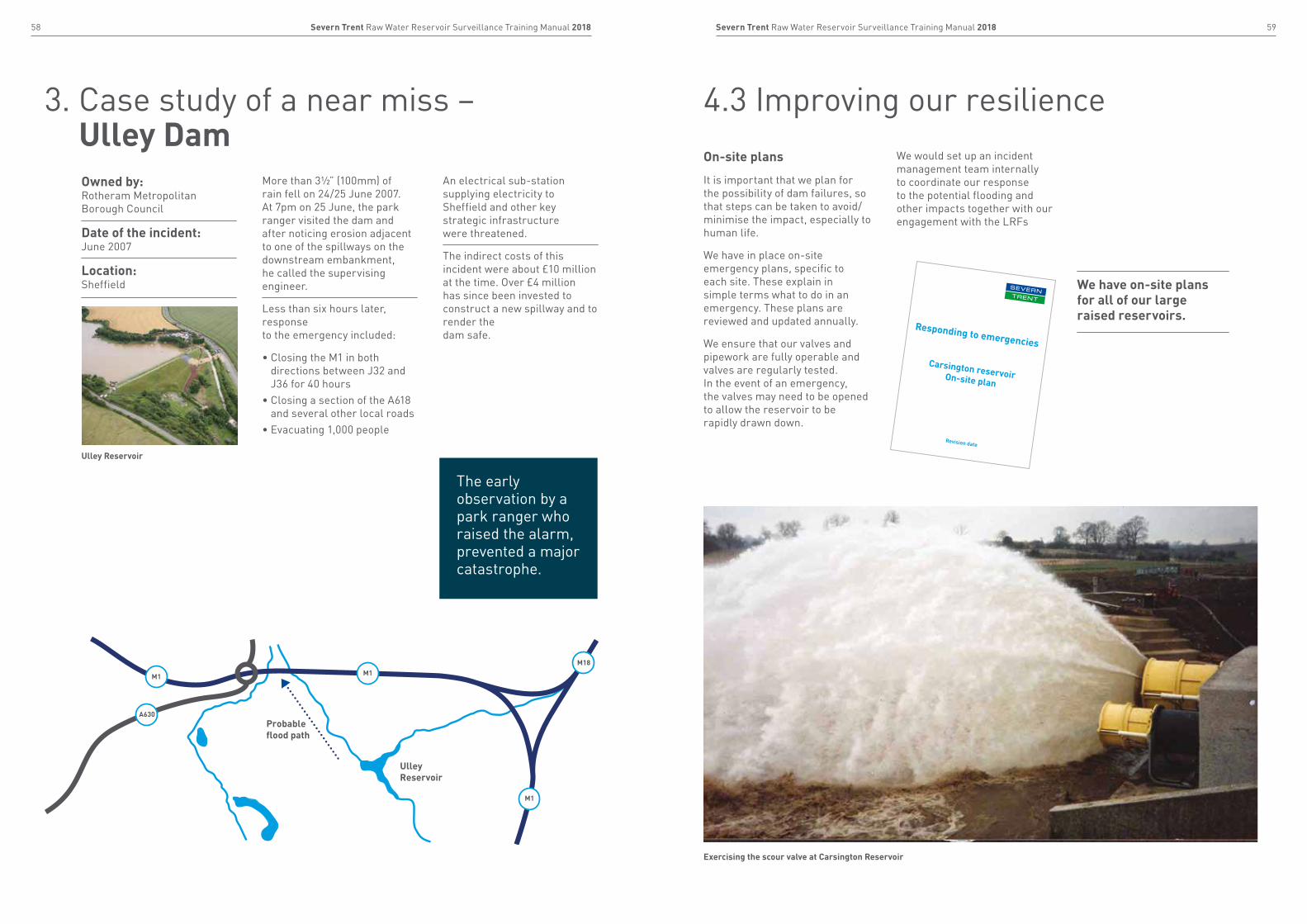
Owned by:Rotheram Metropolitan Borough Council
Date of the incident:June 2007
Location: Sheffield
More than 3½” (100mm) of rain fell on 24/25 June 2007. At 7pm on 25 June, the park ranger visited the dam and after noticing erosion adjacent to one of the spillways on the downstream embankment, he called the supervising engineer.
Less than six hours later, response to the emergency included:
• Closing the M1 in both directions between J32 and J36 for 40 hours
• Closing a section of the A618 and several other local roads
• Evacuating 1,000 people
An electrical sub-station supplying electricity to Sheffield and other key strategic infrastructure were threatened.
The indirect costs of this incident were about £10 million at the time. Over £4 million has since been invested to construct a new spillway and to render the dam safe.
Ulley Reservoir
3. Case study of a near miss – Ulley Dam
UlleyReservoir
Probable flood path
M1 M1M18
M1
A630
The early observation by a park ranger who raised the alarm, prevented a major catastrophe.
On-site plans
It is important that we plan for the possibility of dam failures, so that steps can be taken to avoid/minimise the impact, especially to human life.
We have in place on-site emergency plans, specific to each site. These explain in simple terms what to do in an emergency. These plans are reviewed and updated annually.
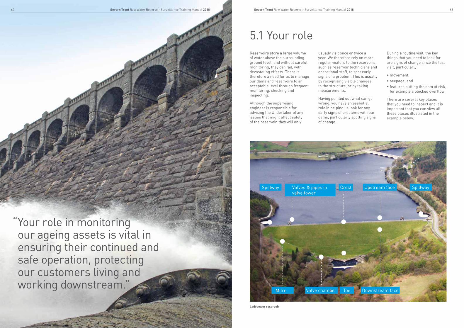
We ensure that our valves and pipework are fully operable and valves are regularly tested. In the event of an emergency, the valves may need to be opened to allow the reservoir to be rapidly drawn down.
We would set up an incident management team internally to coordinate our response to the potential flooding and other impacts together with our engagement with the LRFs
4.3 Improving our resilience
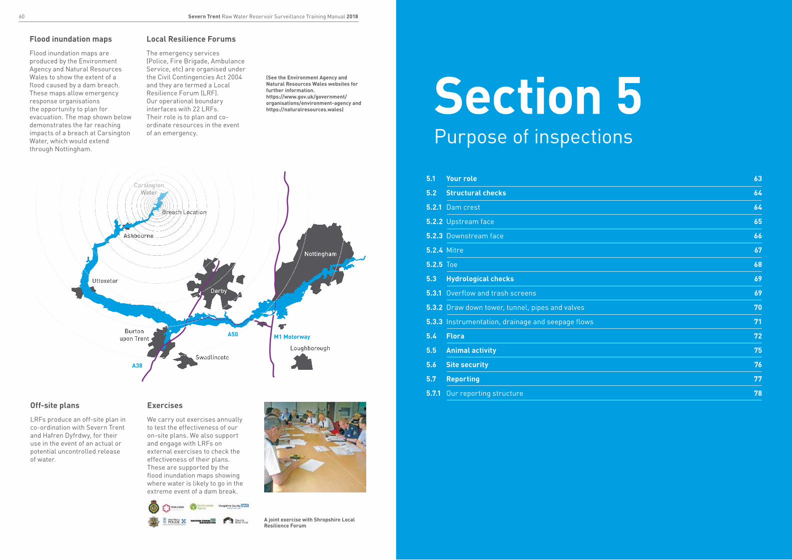
We have on-site plans for all of our large raised reservoirs.
Responding to emergencies
Carsington reservoir On-site plan
Revision date
Exercising the scour valve at Carsington Reservoir
60 61Severn Trent Raw Water Reservoir Surveillance Training Manual 2018 Severn Trent Raw Water Reservoir Surveillance Training Manual 2018
5.1 Your role 63
5.2 Structural checks 64
5.2.1 Dam crest 64
5.2.2 Upstream face 65
5.2.3 Downstream face 66
5.2.4 Mitre 67
5.2.5 Toe 68
5.3 Hydrological checks 69
5.3.1 Overflow and trash screens 69
5.3.2 Draw down tower, tunnel, pipes and valves 70
5.3.3 Instrumentation, drainage and seepage flows 71
5.4 Flora 72
5.5 Animal activity 75
5.6 Site security 76
5.7 Reporting 77
5.7.1 Our reporting structure 78
Flood inundation maps
Flood inundation maps are produced by the Environment Agency and Natural Resources Wales to show the extent of a flood caused by a dam breach. These maps allow emergency response organisations the opportunity to plan for evacuation. The map shown below demonstrates the far reaching impacts of a breach at Carsington Water, which would extend through Nottingham.
Local Resilience Forums
The emergency services (Police, Fire Brigade, Ambulance Service, etc) are organised under the Civil Contingencies Act 2004 and they are termed a Local Resilience Forum (LRF). Our operational boundary interfaces with 22 LRFs. Their role is to plan and co-ordinate resources in the event of an emergency.
Off-site plans
LRFs produce an off-site plan in co-ordination with Severn Trent and Hafren Dyfrdwy, for their use in the event of an actual or potential uncontrolled release of water.
Exercises
We carry out exercises annually to test the effectiveness of our on-site plans. We also support and engage with LRFs on external exercises to check the effectiveness of their plans. These are supported by the flood inundation maps showing where water is likely to go in the extreme event of a dam break.
A joint exercise with Shropshire Local Resilience Forum
(See the Environment Agency and Natural Resources Wales websites for further information.https://www.gov.uk/government/organisations/environment-agency and https://naturalresources.wales)
Nottingham
Derby
Burtonupon Trent
CarsingtonWater
Ashbourne
Uttoxeter
Breach Location
SwadlincoteLoughborough
M1 MotorwayA50
A38
Section 5Purpose of inspections
63Severn Trent Raw Water Reservoir Surveillance Training Manual 201862 Severn Trent Raw Water Reservoir Surveillance Training Manual 2018
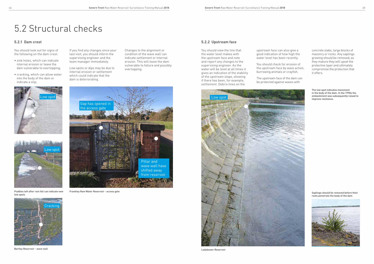
5.1 Your roleReservoirs store a large volume of water above the surrounding ground level, and without careful monitoring, they can fail, with devastating effects. There is therefore a need for us to manage our dams and reservoirs to an acceptable level through frequent monitoring, checking and inspecting.
Although the supervising engineer is responsible for advising the Undertaker of any issues that might affect safety of the reservoir, they will only
usually visit once or twice a year. We therefore rely on more regular visitors to the reservoirs, such as reservoir technicians and operational staff, to spot early signs of a problem. This is usually by recognising visible changes to the structure, or by taking measurements.
Having pointed out what can go wrong, you have an essential role in helping us look for any early signs of problems with our dams, particularly spotting signs of change.
During a routine visit, the key things that you need to look for are signs of change since the last visit, particularly:
• movement;• seepage; and• features putting the dam at risk,
for example a blocked overflow.
There are several key places that you need to inspect and it is important that you can view all these places illustrated in the example below.
Ladybower reservoir
Spillway
Mitre Valve chamber Downstream face
SpillwayUpstream faceValves & pipes in valve tower
Crest
Toe
“ Your role in monitoring our ageing assets is vital in ensuring their continued and safe operation, protecting our customers living and working downstream.”
65Severn Trent Raw Water Reservoir Surveillance Training Manual 201864 Severn Trent Raw Water Reservoir Surveillance Training Manual 2018
5.2 Structural checks5.2.1 Dam crest 5.2.2 Upstream face
You should look out for signs of the following on the dam crest:
• sink holes, which can indicate internal erosion or leave the dam vulnerable to overtopping;
• cracking, which can allow water into the body of the dam or indicate a slip;
If you find any changes since your last visit, you should inform the supervising engineer and the team manager immediately.
Low spots or dips may be due to internal erosion or settlement which could indicate that the dam is deteriorating.
Changes to the alignment or condition of the wave wall can indicate settlement or internal erosion. This will leave the dam vulnerable to failure and possibly overtopping.
You should view the line that the water level makes with the upstream face and note and report any changes to the supervising engineer. As the water will be level at all times it gives an indication of the stability of the upstream slope, showing if there has been, for example, settlement. Debris lines on the
upstream face can also give a good indication of how high the water level has been recently.
You should check for erosion of the upstream face by wave action, burrowing animals or crayfish.
The upstream face of the dam can be protected against waves with
concrete slabs, large blocks of masonry or rocks. Any saplings growing should be removed; as they mature they will upset the protective layer and ultimately compromise the protection that it offers.
Puddles left after rain fall can indicate new low spots
Bartley Reservoir - wave wall
Frankley Raw Water Reservoir - access gate
Ladybower Reservoir
Saplings should be removed before their roots penetrate the body of the dam
Low spot
Gap has opened in the access gate
Pillar and wave wall have shifted away from reservoir
Low spot
Cracking
The low spot indicates movement in the body of the dam. In the 1990s the embankment was subsequently raised to improve resilience.Low spot
67Severn Trent Raw Water Reservoir Surveillance Training Manual 201866 Severn Trent Raw Water Reservoir Surveillance Training Manual 2018
Lake Vyrnwy
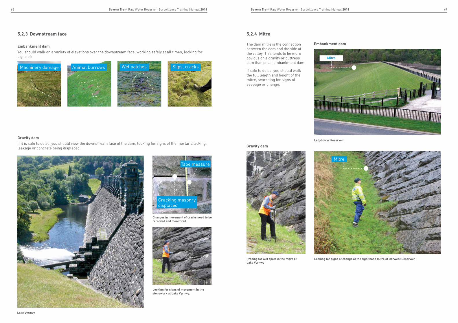
Embankment damYou should walk on a variety of elevations over the downstream face, working safely at all times, looking for signs of:
Gravity damIf it is safe to do so, you should view the downstream face of the dam, looking for signs of the mortar cracking, leakage or concrete being displaced. Gravity dam
Embankment dam
5.2.3 Downstream face 5.2.4 Mitre
Animal burrowsMachinery damage Wet patches Slips, cracks
Changes in movement of cracks need to be recorded and monitored.
Looking for signs of movement in the stonework at Lake Vyrnwy.
Cracking masonry displaced
Tape measure
The dam mitre is the connection between the dam and the side of the valley. This tends to be more obvious on a gravity or buttress dam than on an embankment dam.
If safe to do so, you should walk the full length and height of the mitre, searching for signs of seepage or change.
Mitre
Ladybower Reservoir
Probing for wet spots in the mitre at Lake Vyrnwy
Looking for signs of change at the right hand mitre of Derwent Reservoir
Mitre

69Severn Trent Raw Water Reservoir Surveillance Training Manual 201868 Severn Trent Raw Water Reservoir Surveillance Training Manual 2018
Embankment dam
5.2.5 Toe
You should walk the entire length of the toe of the dam, checking for soft or wet areas as these may indicate seepage. You should look for and record any changes since your last visit.
Particular types of plant, for example marsh grass and reeds, thrive on wet or damp ground and are good indicators of seepage.
It is important to look carefully at plants, asking yourself:
• whether they were there during your last visit;
• are they more overgrown or have they died off since before;
• have they changed in any other way.
If you find any changes since your last visit, you should inform the supervising engineer and the team manager immediately.
Lower Shustoke Reservoir
Bartley Reservoir
Pen-y-Gwely Reservoir
Witcombe Reservoir Ladderedge Reservoir
Marsh grass
Wet area
Toe
Whilst the grass growth is uniform along the toe of this reservoir, are there any new softer wet areas not previously present?
5.3 Hydrological checks5.3.1 Overflow and trash screens
How often the spillway needs to be checked or cleared depends on the amount of debris that gathers daily at the reservoir. You should check this more frequently in the autumn and in particular after heavy rain or windy days.
Where they are used, you should also check the trash screen to make sure there is no build up of debris that could cause a blockage leading to increased water levels within the reservoir during a flood event. Ultimately blockages could lead to the possibility of overtopping of the dam, which would threaten the overall safety of the structure.
Inspect the condition of the overflow and channel to make sure it is not damaged in any way. Report any defects or changes found.
Check trash screen
Example of a blocked spillway
If vegetation is growing around the spillway, request that it is cut back to try and prevent debris getting trapped within the spillway.
Check the spillway is clear. Remove any debris if it is safe to do so.
71Severn Trent Raw Water Reservoir Surveillance Training Manual 201870 Severn Trent Raw Water Reservoir Surveillance Training Manual 2018
5.3.2 Draw down tower, tunnel, pipes and valves 5.3.3 Instrumentation, drainage and seepage flows
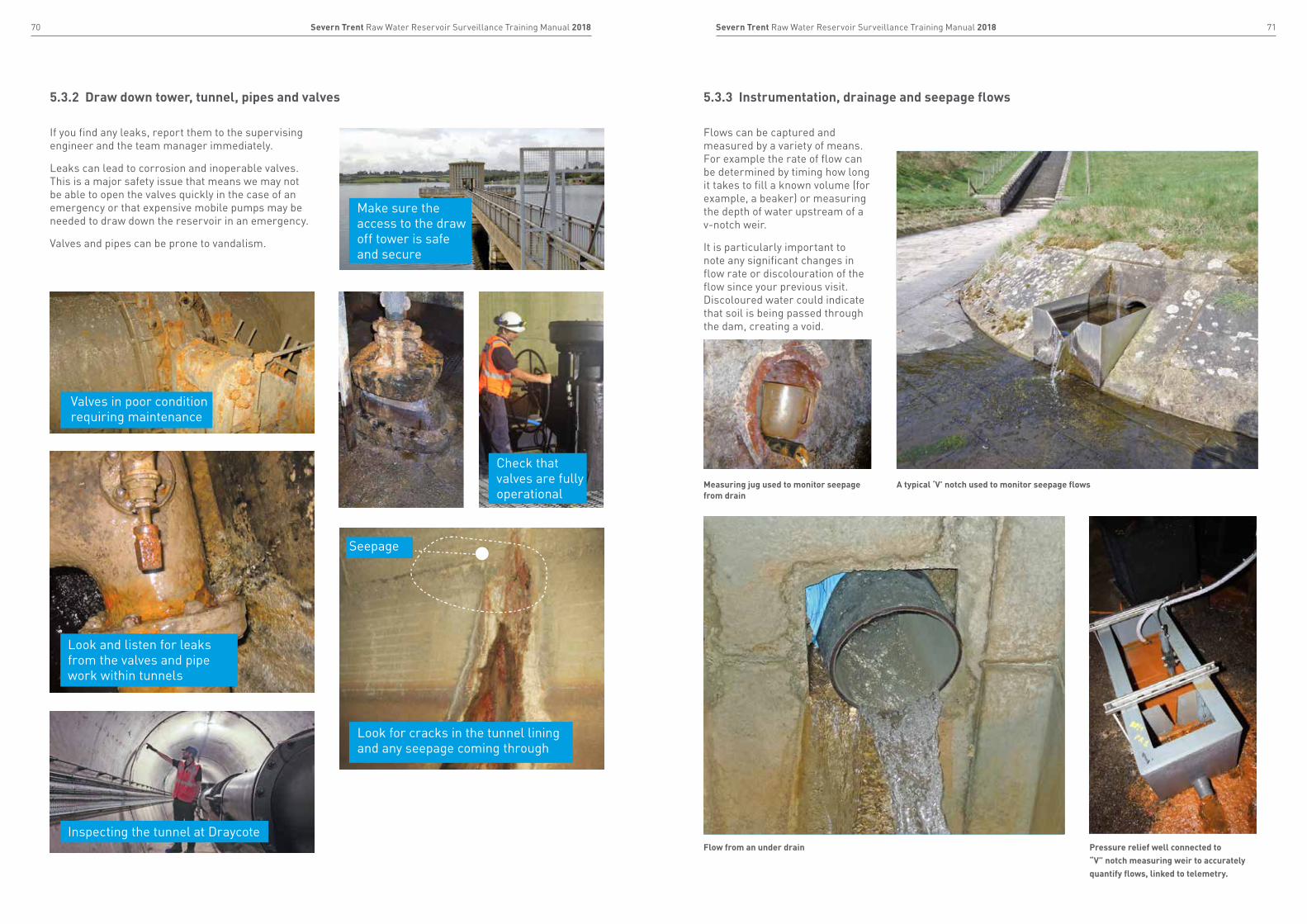
If you find any leaks, report them to the supervising engineer and the team manager immediately.
Leaks can lead to corrosion and inoperable valves. This is a major safety issue that means we may not be able to open the valves quickly in the case of an emergency or that expensive mobile pumps may be needed to draw down the reservoir in an emergency.
Valves and pipes can be prone to vandalism.
Flows can be captured and measured by a variety of means. For example the rate of flow can be determined by timing how long it takes to fill a known volume (for example, a beaker) or measuring the depth of water upstream of a v-notch weir.
It is particularly important to note any significant changes in flow rate or discolouration of the flow since your previous visit. Discoloured water could indicate that soil is being passed through the dam, creating a void.
Valves in poor condition requiring maintenance
Look and listen for leaks from the valves and pipe work within tunnels
Inspecting the tunnel at Draycote
Make sure the access to the draw off tower is safe and secure
Check that valves are fully operational
Look for cracks in the tunnel lining and any seepage coming through
Seepage
Measuring jug used to monitor seepage from drain
Pressure relief well connected to “V” notch measuring weir to accurately quantify flows, linked to telemetry.
A typical ‘V’ notch used to monitor seepage flows
Flow from an under drain
73Severn Trent Raw Water Reservoir Surveillance Training Manual 201872 Severn Trent Raw Water Reservoir Surveillance Training Manual 2018
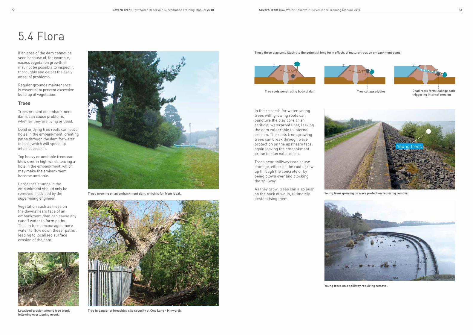
5.4 FloraIf an area of the dam cannot be seen because of, for example, excess vegetation growth, it may not be possible to inspect it thoroughly and detect the early onset of problems.
Regular grounds maintenance is essential to prevent excessive build up of vegetation.
Trees
Trees present on embankment dams can cause problems whether they are living or dead.
Dead or dying tree roots can leave holes in the embankment, creating paths through the dam for water to leak, which will speed up internal erosion.
Top heavy or unstable trees can blow over in high winds leaving a hole in the embankment, which may make the embankment become unstable.
Large tree stumps in the embankment should only be removed if advised by the supervising engineer.
Vegetation such as trees on the downstream face of an embankment dam can cause any runoff water to form paths. This, in turn, encourages more water to flow down these “paths”, leading to localised surface erosion of the dam.
In their search for water, young trees with growing roots can puncture the clay core or an artificial waterproof liner, leaving the dam vulnerable to internal erosion. The roots from growing trees can break through wave protection on the upstream face, again leaving the embankment prone to internal erosion.
Trees near spillways can cause damage, either as the roots grow up through the concrete or by being blown over and blocking the spillway.
As they grow, trees can also push on the back of walls, ultimately destabilising them.
Localised erosion around tree trunk following overtopping event.
Tree in danger of breaching site security at Cow Lane - Minworth.
Trees growing on an embankment dam, which is far from ideal.
These three diagrams illustrate the potential long term effects of mature trees on embankment dams:
Tree roots penetrating body of dam Tree collapsed/dies Dead roots form leakage path triggering internal erosion
Young trees on a spillway requiring removal
Young trees growing on wave protection requiring removal
Young trees
75Severn Trent Raw Water Reservoir Surveillance Training Manual 201874 Severn Trent Raw Water Reservoir Surveillance Training Manual 2018
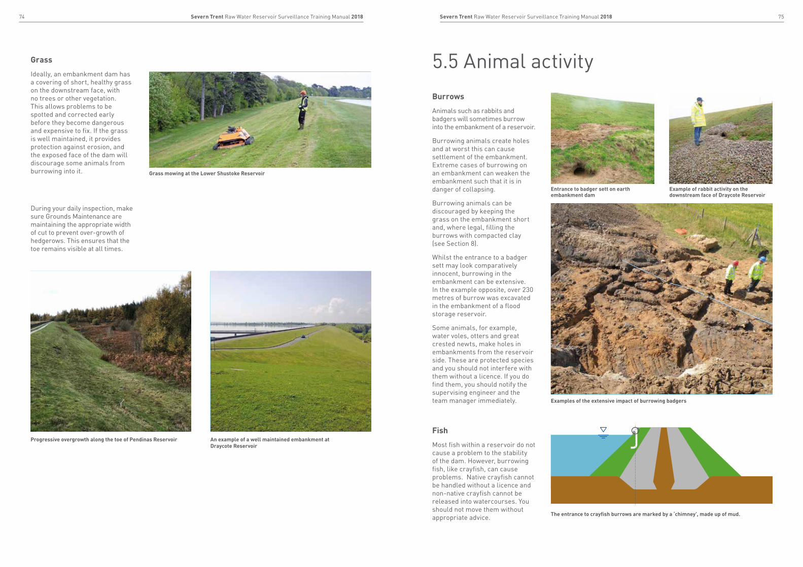
Burrows
Animals such as rabbits and badgers will sometimes burrow into the embankment of a reservoir.
Burrowing animals create holes and at worst this can cause settlement of the embankment. Extreme cases of burrowing on an embankment can weaken the embankment such that it is in danger of collapsing.
Burrowing animals can be discouraged by keeping the grass on the embankment short and, where legal, filling the burrows with compacted clay (see Section 8).
Whilst the entrance to a badger sett may look comparatively innocent, burrowing in the embankment can be extensive.In the example opposite, over 230 metres of burrow was excavated in the embankment of a flood storage reservoir.
Some animals, for example, water voles, otters and great crested newts, make holes in embankments from the reservoir side. These are protected species and you should not interfere with them without a licence. If you do find them, you should notify the supervising engineer and the team manager immediately.
Grass
Ideally, an embankment dam has a covering of short, healthy grass on the downstream face, with no trees or other vegetation. This allows problems to be spotted and corrected early before they become dangerous and expensive to fix. If the grass is well maintained, it provides protection against erosion, and the exposed face of the dam will discourage some animals from burrowing into it.
During your daily inspection, make sure Grounds Maintenance are maintaining the appropriate width of cut to prevent over-growth of hedgerows. This ensures that the toe remains visible at all times.
Grass mowing at the Lower Shustoke Reservoir
Progressive overgrowth along the toe of Pendinas Reservoir An example of a well maintained embankment at Draycote Reservoir
Examples of the extensive impact of burrowing badgers
5.5 Animal activity
The entrance to crayfish burrows are marked by a ‘chimney’, made up of mud.
Fish
Most fish within a reservoir do not cause a problem to the stability of the dam. However, burrowing fish, like crayfish, can cause problems. Native crayfish cannot be handled without a licence and non-native crayfish cannot be released into watercourses. You should not move them without appropriate advice.
Entrance to badger sett on earth embankment dam
Example of rabbit activity on the downstream face of Draycote Reservoir
77Severn Trent Raw Water Reservoir Surveillance Training Manual 201876 Severn Trent Raw Water Reservoir Surveillance Training Manual 2018
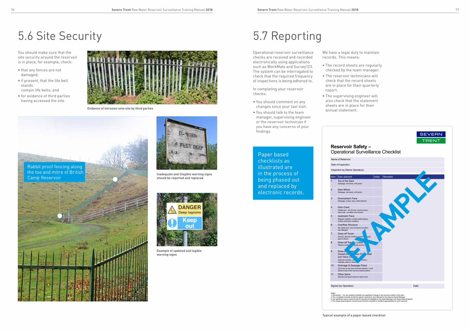
5.6 Site Security 5.7 ReportingYou should make sure that the site security around the reservoir is in place, for example, check:
• that any fences are not damaged;
• if present, that the life belt stands contain life belts; and
• for evidence of third parties having accessed the site.
Operational reservoir surveillance checks are received and recorded electronically using applications such as WorkMate and Survey123. The system can be interrogated to check that the required frequency of inspections is being adhered to.
In completing your reservoir checks:
• You should comment on any changes since your last visit.
• You should talk to the team manager, supervising engineer or the reservoir technician if you have any concerns of your findings.
We have a legal duty to maintain records. This means:
• The record sheets are regularly checked by the team manager.
• The reservoir technicians will check that the record sheets are in place for their quarterly report.
• The supervising engineer will also check that the statement sheets are in place for their annual statement.Evidence of intrusion onto site by third parties
Inadequate and illegible warning signs should be reported and replaced
Example of updated and legible warning signs
Rabbit proof fencing along the toe and mitre of British Camp Reservoir Item Dam element Initial Remarks
1 Toe of the Dam(Seepage, wet areas, soft spots)
2 Dam Mitres(Seepage, wet areas, soft spots)
3 Downstream Face(Seepage, cracks, tears, deformations)
4 Dam Crest(Settlement – line & level, cracks & tears, wave wall – condition, line & level)
5 Upstream Face(Regular waterline, surface deformations, surface protection condition)
6 Overflow Structure(No obstruction, weir & channel condition, weir leakage)
7 Draw-off Tower(Access, general condition, cracks, seepage, pipe & valves)
8 Draw-off Tower – Lower level(Observe extent of seepage across floor)
9 Draw-off Tower – Closed Downstream Portal Wall and Valve Camber(General condition, cracks, deformation, seepage, pipes & valves)
10 Drainage & Seepage Flows(Lift cover on toe drain terminal chamber ‘J’ and observe rate of flow and any discolouration)
11 Other Items(Record and report reservoir water level)
Name of Reservoir:
Date of inspection:
Inspection by (Name Operative):
Signed (by Operative): Date:
Notes1. Remember – You are looking to identify any significant change in the normal condition of the dam.2. The completed checklist should be signed, returned to and retained by the relevant Asset Manager3. Any significant issues noted should be reported immediately to the Asset Manager and Supervising Engineer.4. The Supervising Engineer should ensure that the checklist is modified appropriately for each reservoir.
Reservoir Safety – Operational Surveillance Checklist
Typical example of a paper based checklist
Paper based checklists as illustrated are in the process of being phased out and replaced by electronic records.
EXAMPLE

79Severn Trent Raw Water Reservoir Surveillance Training Manual 201878 Severn Trent Raw Water Reservoir Surveillance Training Manual 2018
6.1 Operating protocols 81
6.2 Inspecting routines 82
6.3 Monitoring 83
To successfully manage our reservoirs, people are key to delivery
ReviewPanel
InspectingEngineers
SupervisingEngineers (ST & HD)
Reservoir Technicians (ST & HD)
Surveyors (ST & HD)
Operators (ST & HD)
5.7.1 Our reporting structure
The Team Manager decides whether the
issue is routine or if the Supervising Engineer should
be called.
CC’d in emails sent to Reservoir Supervising
Engineer.
In the event of a non-routine issue, the supervising engineer should be called/contacted as shown in purple.
CEO
Production Director
Head of Water Treatment
Area Operations Lead
Team Manager
Operator
Head of Dams, Assurance and Standards
Chief Engineer
Dams and Reservoirs Manager
Supervising Engineer
Reservoir Technician
If you have any concerns following your surveillance visit please raise them. Section 6
Operating, inspecting and monitoring
Please remember, there is no such thing as a false alarm!
81Severn Trent Raw Water Reservoir Surveillance Training Manual 201880 Severn Trent Raw Water Reservoir Surveillance Training Manual 2018
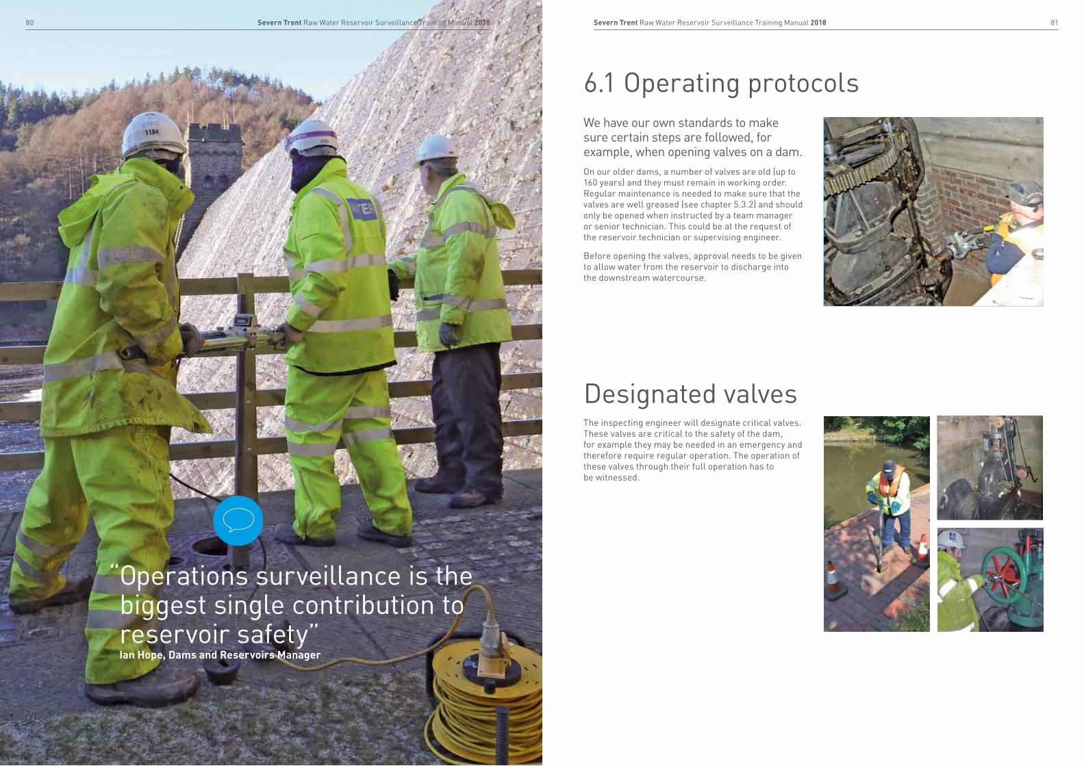
6.1 Operating protocols
Designated valves
“ Operations surveillance is the biggest single contribution to reservoir safety” Ian Hope, Dams and Reservoirs Manager
We have our own standards to make sure certain steps are followed, for example, when opening valves on a dam.On our older dams, a number of valves are old (up to 160 years) and they must remain in working order. Regular maintenance is needed to make sure that the valves are well greased (see chapter 5.3.2) and should only be opened when instructed by a team manager or senior technician. This could be at the request of the reservoir technician or supervising engineer.
Before opening the valves, approval needs to be given to allow water from the reservoir to discharge into the downstream watercourse.
The inspecting engineer will designate critical valves. These valves are critical to the safety of the dam, for example they may be needed in an emergency and therefore require regular operation. The operation of these valves through their full operation has to be witnessed.
83Severn Trent Raw Water Reservoir Surveillance Training Manual 201882 Severn Trent Raw Water Reservoir Surveillance Training Manual 2018
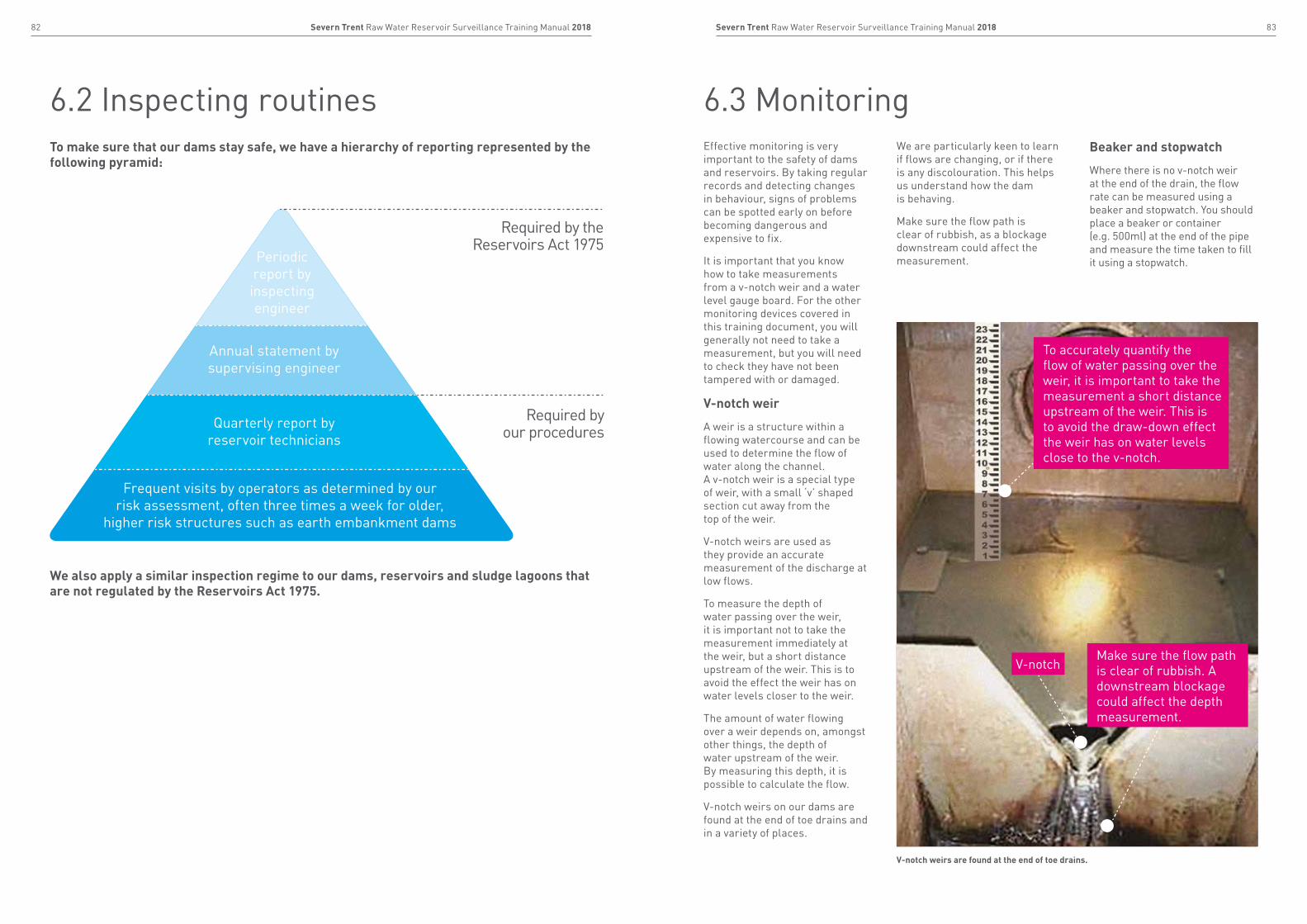
6.3 Monitoring6.2 Inspecting routinesEffective monitoring is very important to the safety of dams and reservoirs. By taking regular records and detecting changes in behaviour, signs of problems can be spotted early on before becoming dangerous and expensive to fix.
It is important that you know how to take measurements from a v-notch weir and a water level gauge board. For the other monitoring devices covered in this training document, you will generally not need to take a measurement, but you will need to check they have not been tampered with or damaged.
V-notch weir
A weir is a structure within a flowing watercourse and can be used to determine the flow of water along the channel. A v-notch weir is a special type of weir, with a small ‘v’ shaped section cut away from the top of the weir.
V-notch weirs are used as they provide an accurate measurement of the discharge at low flows.
To measure the depth of water passing over the weir, it is important not to take the measurement immediately at the weir, but a short distance upstream of the weir. This is to avoid the effect the weir has on water levels closer to the weir.
The amount of water flowing over a weir depends on, amongst other things, the depth of water upstream of the weir. By measuring this depth, it is possible to calculate the flow.
V-notch weirs on our dams are found at the end of toe drains and in a variety of places.
We are particularly keen to learn if flows are changing, or if there is any discolouration. This helps us understand how the dam is behaving.
Make sure the flow path is clear of rubbish, as a blockage downstream could affect the measurement.
Beaker and stopwatch
Where there is no v-notch weir at the end of the drain, the flow rate can be measured using a beaker and stopwatch. You should place a beaker or container (e.g. 500ml) at the end of the pipe and measure the time taken to fill it using a stopwatch.
To make sure that our dams stay safe, we have a hierarchy of reporting represented by the following pyramid:
Periodic report by inspecting engineer
Annual statement by supervising engineer
Quarterly report by reservoir technicians
Frequent visits by operators as determined by our risk assessment, often three times a week for older,
higher risk structures such as earth embankment dams
Required by the Reservoirs Act 1975
Required by our procedures
We also apply a similar inspection regime to our dams, reservoirs and sludge lagoons that are not regulated by the Reservoirs Act 1975.
V-notchMake sure the flow path is clear of rubbish. A downstream blockage could affect the depth measurement.
V-notch weirs are found at the end of toe drains.
To accurately quantify the flow of water passing over the weir, it is important to take the measurement a short distance upstream of the weir. This is to avoid the draw-down effect the weir has on water levels close to the v-notch.
85Severn Trent Raw Water Reservoir Surveillance Training Manual 201884 Severn Trent Raw Water Reservoir Surveillance Training Manual 2018
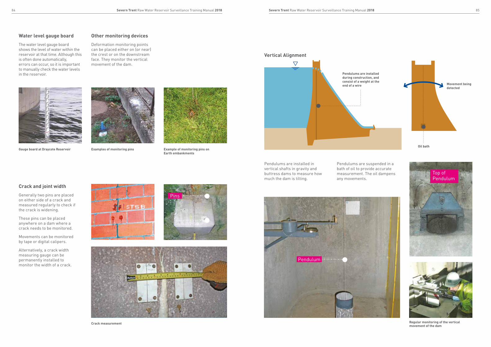
Water level gauge board
The water level gauge board shows the level of water within the reservoir at that time. Although this is often done automatically, errors can occur, so it is important to manually check the water levels in the reservoir.
Other monitoring devices
Deformation monitoring points can be placed either on (or near) the crest or on the downstream face. They monitor the vertical movement of the dam.
Pendulums are installed in vertical shafts in gravity and buttress dams to measure how much the dam is tilting.
Pendulums are suspended in a bath of oil to provide accurate measurement. The oil dampens any movements.
Vertical Alignment
Crack and joint width
Generally two pins are placed on either side of a crack and measured regularly to check if the crack is widening.
These pins can be placed anywhere on a dam where a crack needs to be monitored.
Movements can be monitored by tape or digital calipers.
Alternatively, a crack width measuring gauge can be permanently installed to monitor the width of a crack.
Gauge board at Draycote Reservoir Examples of monitoring pins Example of monitoring pins on Earth embankments
Crack measurement Regular monitoring of the vertical movement of the dam
Pendulums are installed during construction, and consist of a weight at the end of a wire
Oil bath
Movement being detected
Top of Pendulum
Pins
Pendulum
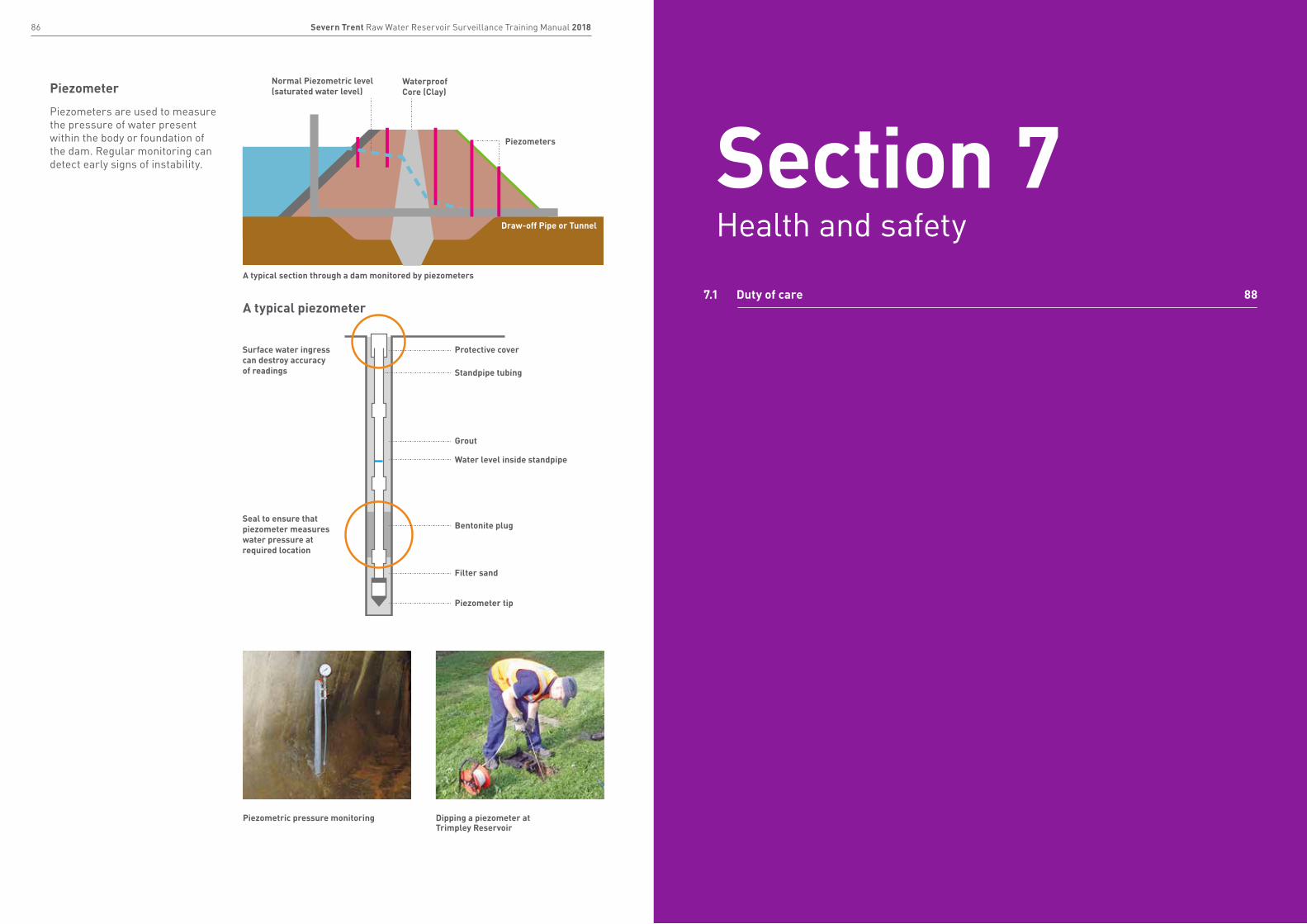
87Severn Trent Raw Water Reservoir Surveillance Training Manual 201886 Severn Trent Raw Water Reservoir Surveillance Training Manual 2018
7.1 Duty of care 88
Piezometer
Piezometers are used to measure the pressure of water present within the body or foundation of the dam. Regular monitoring can detect early signs of instability.
Piezometers
Protective coverSurface water ingress can destroy accuracy of readings
Seal to ensure that piezometer measures water pressure at required location
Standpipe tubing
Grout
Water level inside standpipe
Bentonite plug
Filter sand
Piezometer tip
A typical section through a dam monitored by piezometers
A typical piezometer
Waterproof Core (Clay)
Normal Piezometric level (saturated water level)
Draw-off Pipe or Tunnel
Piezometric pressure monitoring Dipping a piezometer at Trimpley Reservoir
Section 7Health and safety
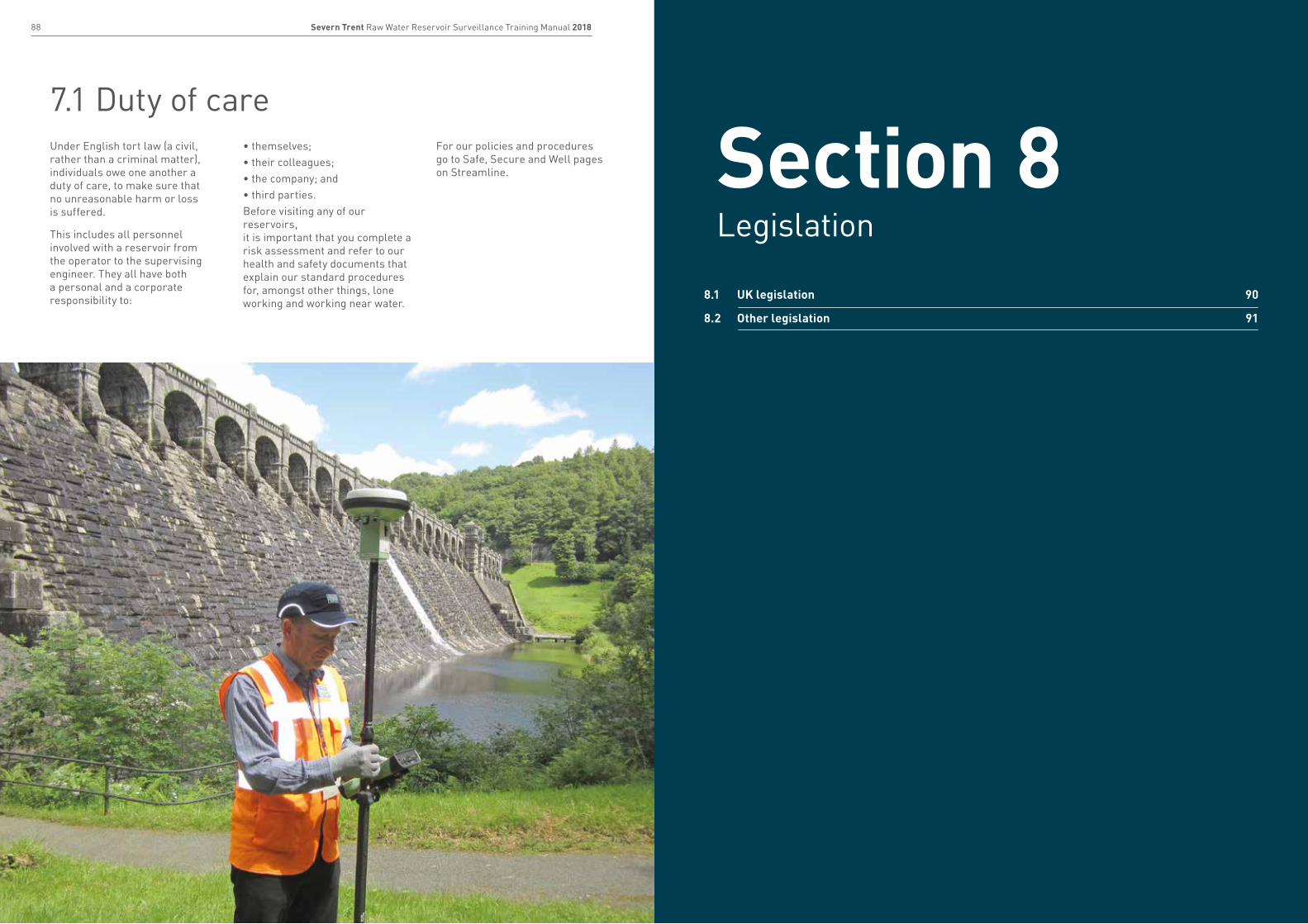
89Severn Trent Raw Water Reservoir Surveillance Training Manual 201888 Severn Trent Raw Water Reservoir Surveillance Training Manual 2018
8.1 UK legislation 90
8.2 Other legislation 91
7.1 Duty of careUnder English tort law (a civil, rather than a criminal matter), individuals owe one another a duty of care, to make sure that no unreasonable harm or loss is suffered.
This includes all personnel involved with a reservoir from the operator to the supervising engineer. They all have both a personal and a corporate responsibility to:
• themselves;• their colleagues;• the company; and • third parties.Before visiting any of our reservoirs, it is important that you complete a risk assessment and refer to our health and safety documents that explain our standard procedures for, amongst other things, lone working and working near water.
For our policies and procedures go to Safe, Secure and Well pages on Streamline. Section 8
Legislation

91Severn Trent Raw Water Reservoir Surveillance Training Manual 201890 Severn Trent Raw Water Reservoir Surveillance Training Manual 2018
8.1 UK legislation 8.2 Other legislation
Our approach
Pre 1930s:
During the early 19th century, the high demand for unpolluted water resulted in a swift increase in the number of reservoirs being built. The majority of these dams were embankment dams with a clay core, constructed by a “rule-of-thumb” method.
Many dams collapsed during construction or when they were first filled with water, creating large flood waves that caused significant damage and killed hundreds of people downstream.
Reservoirs (Safety Provisions) Act 1930:
After two reservoir failures in 1925 (See Coedty and Eigau Case Study), legislation was eventually introduced in 1930, ensuring that all large raised reservoirs would be inspected at least every 10 years by a suitably qualified engineer (inspecting engineer).
Reservoirs Act 1975:
No one has been killed following dam failures in the UK since the 1930 Act was introduced. There have, however, been serious incidents and failures. The Reservoirs Act 1975 updated the 1930 Act.
Key aspects include:
• all large raised reservoirs are registered with the relevant enforcement agency. For England this has been the Environment Agency since October 2004, and for Wales this has been Natural Resources Wales since April 2013;
• each reservoir must have a suitably qualified engineer (supervising engineer) who must keep the owners informed of any aspects that may affect its safety;
• as the supervising engineer will not usually visit more than once every six months, they depend on reservoir technicians and operational staff who visit the site far more frequently to pick up any significant changes.
Floods and Water Management Act 2010:
The Floods and Water Management Act 2010 contains amendments to sections of the Reservoirs Act 1975.
As the safety of reservoirs with a raised volume of less than 25,000m³ is not covered by the 1975 Reservoirs Act, they can sometimes be in a poor condition, which has resulted in a number of “near-misses” in recent years.
The implementation of the Flood and Water Management Act 2010 is being phased. It amends the 1975 Act, so that all raised reservoirs with a volume of 10,000m³ or above (or a chain of smaller reservoirs whose total volume held above the surrounding land is greater than 10,000m³) have to be registered with the regulator (Environment Agency/Natural Resources Wales). They will then be allocated a risk category (“not high risk” or “high risk”) depending on whether the population downstream are exposed to risk of dam breach. “High risk” reservoirs will need to be regularly inspected and supervised.
The level of observation and inspection needed is based on the risk associated with the reservoir. This lower volumetric threshold has already been introduced in Wales, and statutory inspections of reservoirs that the Act applies to have already started to take place.
Health and Safety at Work etc. Act 1974:
This Act enforces general duties on every person concerned with work. The Act places duties upon employers with regard to their employees and third parties to not intentionally interfere with items provided for in the interests of health, safety and welfare.
For UK H&S legislation, Please see www.hse.gov.uk.
Environmental and Wildlife
• the Protection of Badgers Act 1992 makes it illegal to harm badgers or their setts;
• the Protection of Birds Act 1954, protects wild birds, their nests and eggs;
• the Wildlife and Countryside Act 1981 makes it an offence to interfere with great crested newts;
• the Wildlife and Countryside Act 1981 also makes it illegal to release non-native crayfish into a watercourse.
Water Resources
The Water Resources Act 1991 controls discharges into watercourses. Water from a reservoir should only be released under the guidance of the supervising engineer. A discharge consent from the Environment Agency or Natural Resources Wales may also be required.
National Parks
The 1949 National Parks and Access to the Countryside Act protects certain areas from development.
Whilst the Reservoirs Act 1975 and the Floods and Water Management Act 2010 are designed to protect life and infrastructure from sudden and uncontrolled releases of water from large raised reservoirs, there are other laws that can have conflicting impacts on dam safety, which includes:
“Being the best at managing reservoir safety in Great Britain”
• A journey, not a destination• Always driving further improvement
Plan
DoAct
The flood released by the collapsed Eigiau and Coedty dams caused devastating damage downstream
Review

93Severn Trent Raw Water Reservoir Surveillance Training Manual 201892 Severn Trent Raw Water Reservoir Surveillance Training Manual 2018
Further information and continuous improvementIf at any time you have any queries regarding this booklet or suggested modifications we are keen to learn from you. In addition, we will also provide further site specific training if it is required. We can provide advice on deformation monitoring, how to overcome constraints on valve operation and surveillance training.
We look forward to hearing from you
AcknowledgmentsST and HD wish to acknowledge the following:
Photographs: Badger sett excavation displayed courtesy John Falkingham Associates
Trees on third party dams courtesy of Dr Andy Hughes, Atkins
Ulley Reservoir courtesy of the Environment Agency
Boltby spillway photographs courtesy of Yorkshire Water

94 Severn Trent Raw Water Reservoir Surveillance Training Manual 2018
For more information:
Call 0345 7 500 500
Textphone 0800 328 1155
Calls to 0800 numbers are free from UK landlines. Calls to 0345 numbers are charged at a local rate and when phoning from a mobile, may be included in your free minutes package.
Severn Trent PO Box 407, Darlington, DL1 9WD
stwater.co.uk
ST.A
H.0
0027
4.B