Embed Size (px)
Citation preview
12 www.aquaret.com
1. Run-of-river
Conventional hydroelectric pow er generation involves the storage of large volumes of water
behind a dam. Run-of-river hydro pow er is used to describe hydroelectric pow er generation
where there is little to no w ater storage.
1.1. History and Development
Hydro pow er has been used for several thousand years. Wooden w ater wheels w ere
stationed on streams and rivers to provide mechanical pow er for processes such as the
grinding of grain. By the end of the 17th century, it became the main source of mechanical
pow er in Europe for various purposes such as paper-making, textiles, and iron w orking.
Hydro pow er played an important role early in the Industrial Revolution. Technological
developments, including highly-eff icient w ater turbine designs and electric generators, during
the 19th century, together with the growth in demand for electricity by the turn of the 20th
century, led to hydroelectric pow er.
1.1.1. Level 2
The grow th in demand for electricity resulted in the construction of electric power plants,
many of them hydro pow ered. The f irst energy generating hydro pow er plant w as at a
private house in Cragside, Northumberland, England in 1870. The w orld’s f irst commercial
hydropow er plant opened in Wisconsin, USA, in 1882. Since then, hydro electric pow er
stations have been built w orldw ide. For an overview of hydropower utilization in Europe
today, see [1].
The ability of conventional hydropow er to meet increasing energy demands is limited. In
order to meet short to medium term EU renew able energy targets, the use of mature and
proven run-of-river technologies could have an important place in Europe, w hile other
renew able energy technologies are being developed.
1.2. Energy Source and Location
Run-of-river energy is derived from the hydrological cycle. Solar energy heats the Earth’s
surface producing w ater vapour which then cools and condenses in the atmosphere to
produce rain and snow . When this falls on high lands, the w ater f lows dow n to the sea
through streams and rivers.

13 www.aquaret.com
The gravitational potential energy of the water due to the elevation drop (i.e. height
difference, or head), is used by w eir and diversion type plants to generate pow er. The
kinetic energy of fast rivers can be harnessed by kinetic energy devices.
Generally speaking, the best resource areas for diversion type schemes are located in
mountainous area or those areas w ith high hills; for weir type schemes, the location of the
energy source is on hills; for kinetic turbines, the location is on a plain.
1.2.1. Geographical Factors
Run-of-river power plants, unlike conventional hydroelectric pow er plants, have little to no
water storage capacity, so are best located on rivers w ith a consistent and steady f low.
Areas with the best resources are those which offer an elevation drop, high annual
precipitation rates, and catchment areas from w hich water will drain into the rivers.
For w eir and diversion type plants, the energy that can be produced increases w ith the
elevation drop of water (i.e. w ater head) making hilly or mountainous regions most suitable.
For the w eir type schemes, a small dam or w eir must be upstream of the plant house.
14 www.aquaret.com
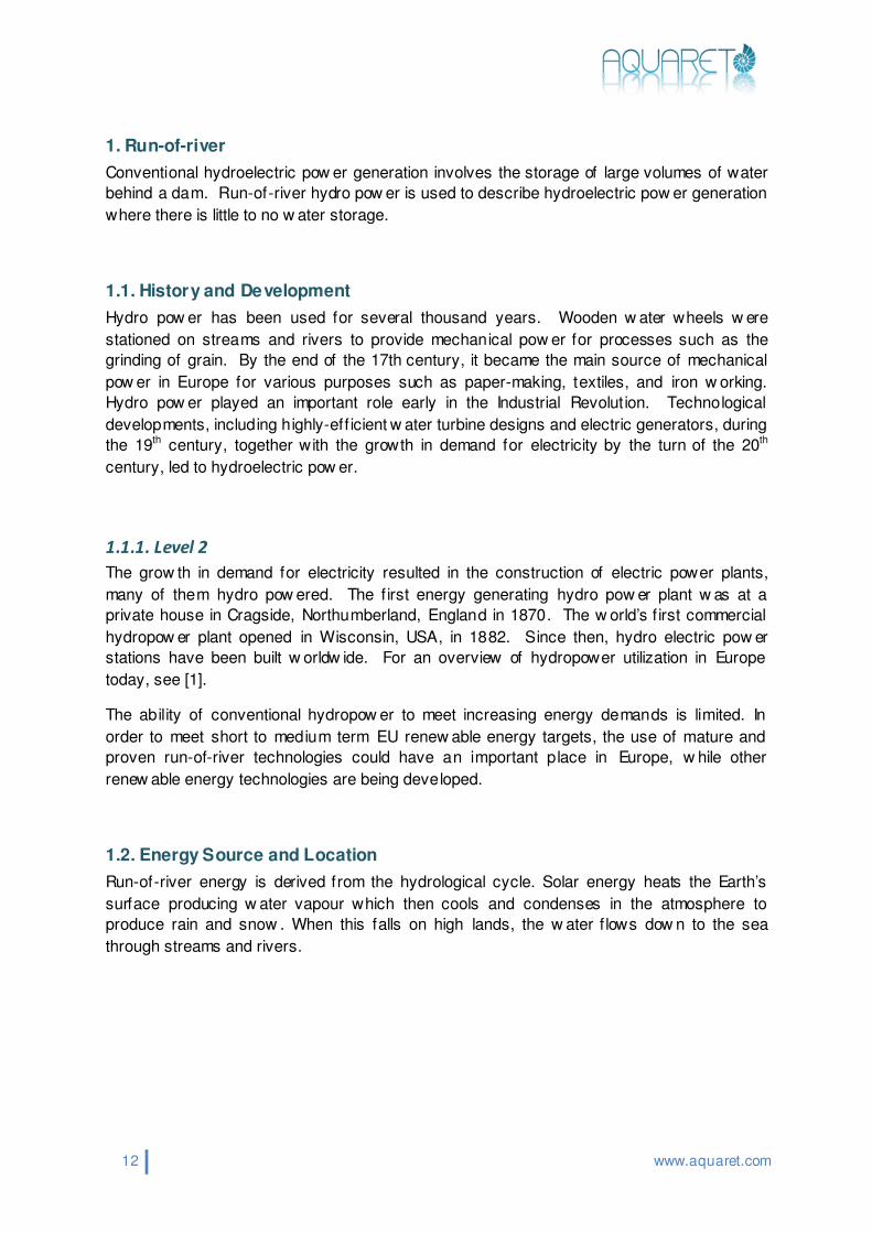
For the purpose of kinetic turbine development, rivers must have the follow ing
characteristics: a year-round continuous f low , suitable depth, a solid and stable riverbed, and
sediment-free w ater. Kinetic turbines w ill be placed in rivers w ith velocities greater than 1
m/s, w ith a steady f low and of a certain depth. Installations are usually situated at strategic
points w here the land provides a natural f low restriction, resulting in locally high velocit ies.
The strongest currents in a river are located in the centre and close to the surface, where
they are not inhibited by friction w ith the river banks and bed. As a river f lows around a bend
it accelerates around the outside and slow s on the inside of the bend.
1.2.2. European Resource Map
Across Europe, the w eakest representation of the run-of-river (i.e. hydropower) resource is
in east and south-east of Europe having the maximum potential of 50 TWh/year, except
Romania and Greece w ith 50-100 TWh/year. Finland, Great Britain and Portugal have only a
weak potential of 50 TWh/year. Germany, Spain and Sw eden have a better potential w ith
betw een 100 and 200 TWh/year. France, Norw ay and Turkey have the best hydraulic
potential resource ranging from 200 to 2300 TWh/year.
The map below indicates the level of resource across Europe.

15 www.aquaret.com
16 www.aquaret.com
1.3. Technology Types
River hydro energy plants are classif ied as run-of-river where there is no signif icant storage
of water. They use the unregulated f low of water to generate energy. Some run-of-river
plants include a low dam or w eir w hich, at most, w ill allow the daily regulation of f low s. Run-
of-river plants can be designed using large f low rates with low head or small f low rates with
high head.
There are three types of run-of-river technology:
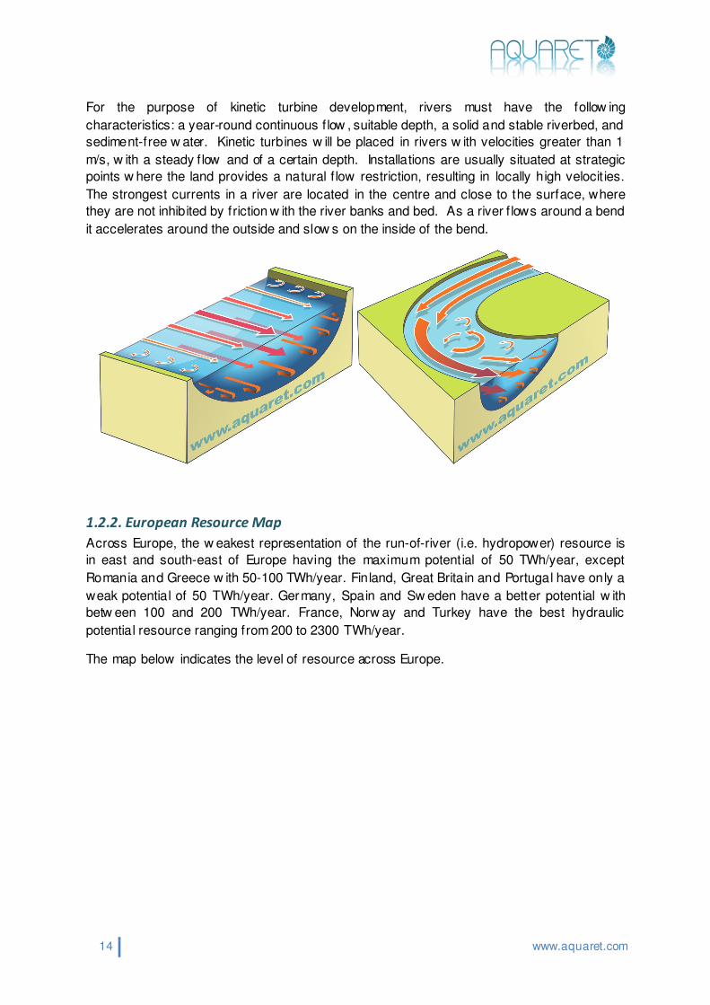
Weir type plant
Water is dammed w ith a low dam or w eir to create a small reservoir and head of w ater. The
water is allow ed to f low through low head turbines housed in the w eir to generate electricity.
The outf low is virtually the same as inflow , and the water is returned directly to the river
without altering the existing f low or water levels.
17 www.aquaret.com
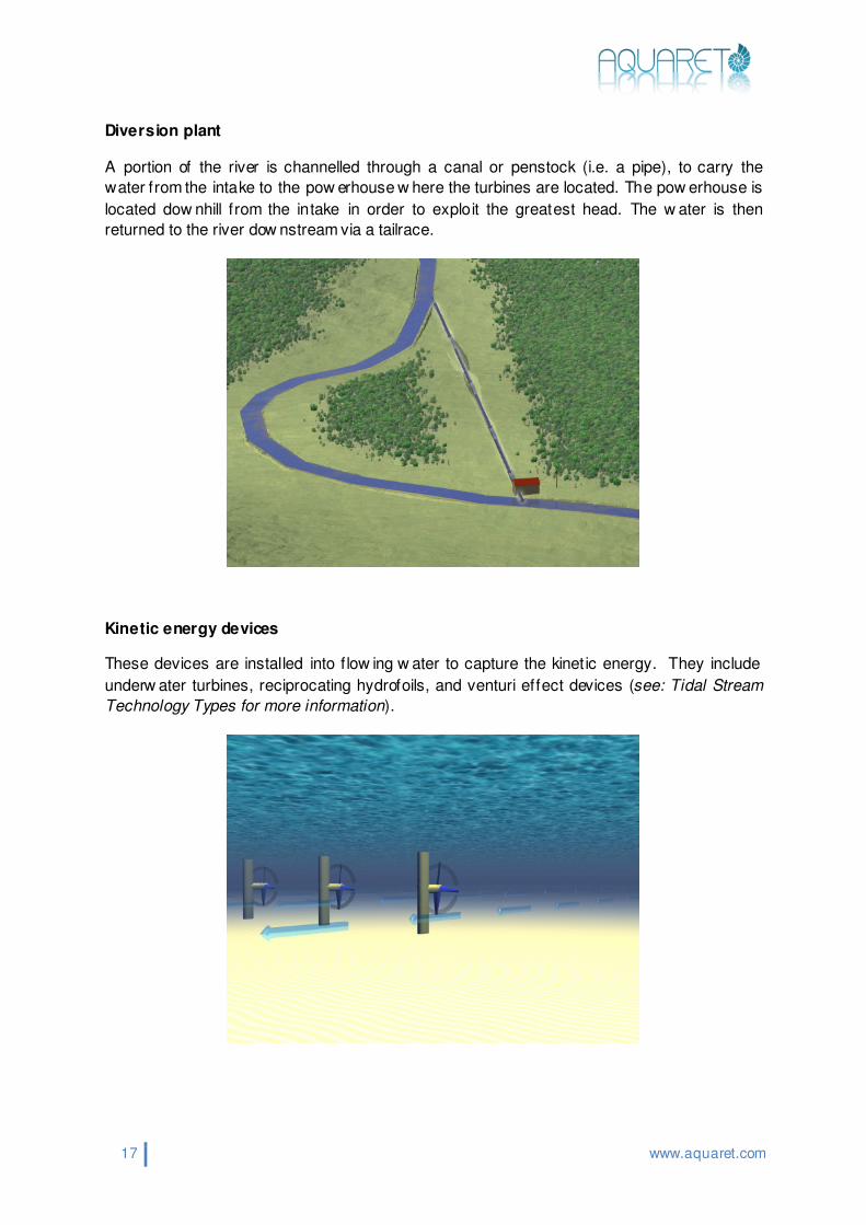
Diversion plant
A portion of the river is channelled through a canal or penstock (i.e. a pipe), to carry the
water from the intake to the pow erhouse w here the turbines are located. The pow erhouse is
located dow nhill from the intake in order to exploit the greatest head. The w ater is then
returned to the river dow nstream via a tailrace.
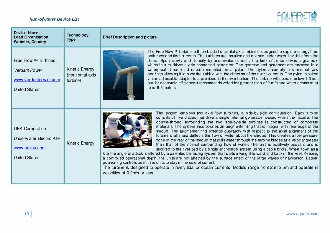
Kinetic energy devices
These devices are installed into f low ing w ater to capture the kinetic energy. They include
underw ater turbines, reciprocating hydrofoils, and venturi effect devices (see: Tidal Stream
Technology Types for more information).

18 www.aquaret.com
1.3.1. Level 2
The potential electrical pow er production from diversion and w eir type plants is calculated
from the head height and the volumetric f low rate as follow s:
Pe = ηρgQH
Where: Pe, electric pow er produced (Watts); η, denotes the overall eff iciency of the plant; ρ,
water density (kg/m3); g, gravitational acceleration, (m/s2); H, the head of w ater (m); Q,
volumetric f low rate (m3/s);.
Kinetic energy devices generate electricity from the kinetic energy in f low ing w ater. The
hydraulic pow er generated by a kinetic turbine is calculated as:
Pe = η 0.5ρAV3
Where: Pe, electric pow er produced (Watts); η, denotes the overall eff iciency of the plant; ρ,
water density (kg/m3); A the sw eep area of the turbine (m2); V, the velocity of the f low (m/s).
The follow ing pages outline various Run-of-River devices.
Run-of-River Device List
19 www.aquaret.com
Dev ice Name, Lead Organisation , Website, Country
Technology Type
Brief Description and picture
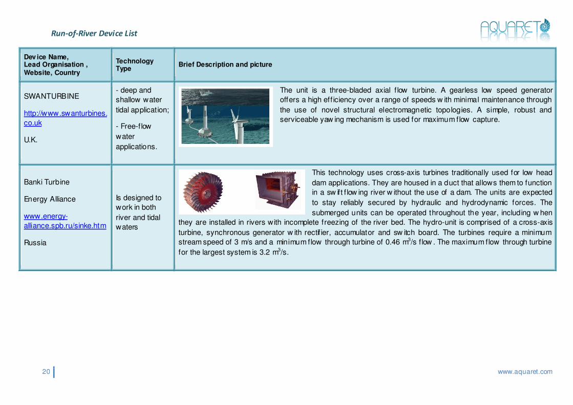
Free Flow ™ Turbines
Verdant Power
www.verdantpow er.com
United States
Kinetic Energy
(horizontal-axis
turbine)
The Free Flow™ Turbine, a three-blade horizontal-axis turbine is designed to capture energy from both river and tidal currents. The turbines are installed and operate under water, invisible from the shore. Spun slowly and steadily by underwater currents, the turbine’s rotor drives a gearbox, which in turn drives a grid-connected generator. The gearbox and generator are encased in a waterproof streamlined nacelle mounted on a pylon. The pylon assembly has internal yaw bearings allowing it to pivot the turbine with the direction of the river’s currents. The pylon is bolted via an adjustable adapter to a pile fixed to the river bottom. The turbine will operate below 1.0 m/s but for economic efficiency it recommends velocities greater than of 2 m/s and water depths of at least 6.5 meters.
UEK Corporation
Underw ater Electric Kite
www.uekus.com
United States
Kinetic Energy
The system employs two axial-flow turbines, a side-by-side configuration. Each turbine consists of five blades that drive a single internal generator housed within the nacelle. The double-shroud surrounding the two side-by-side turbines is constructed of composite materials. The system incorporates an augmenter ring that is integral with rear edge of the shroud. The augmenter ring extends outwardly with respect to the axial alignment of the turbine shafts and deflects the flow of water about the shroud. This creates a low pressure zone of the rear of the shroud that pulls water through the turbine blades at a velocity greater than that of the normal surrounding flow of water. The unit is positively buoyant and is secured to the river bed by a single anchorage system using a cable bridle. When flown as a
kite the angle of attack is altered by a patented ballasting system that shifts a weight forward and back in the keel. Keeping a controlled operational depth, the units are not affected by the surface effect of the large waves or navigation. Lateral positioning controls permit the units to stay in the core of current.
The turbine is designed to operate in river, tidal or ocean currents. Models range from 2m to 5m and operate in
velocities of 0.2m/s or less.
Run-of-River Device List
20 www.aquaret.com
Dev ice Name, Lead Organisation , Website, Country
Technology Type
Brief Description and picture
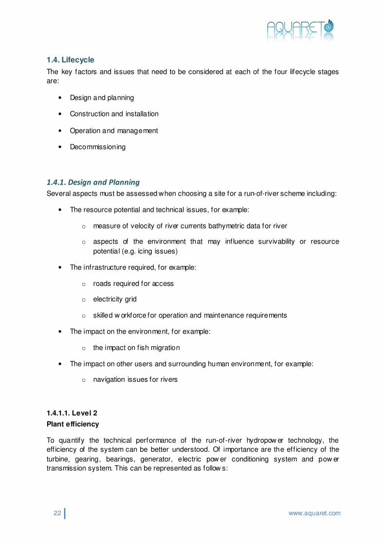
SWANTURBINE
http://www.swanturbines.
co.uk
U.K.
- deep and
shallow water
tidal application;
- Free-flow
water
applications.
The unit is a three-bladed axial f low turbine. A gearless low speed generator
offers a high eff iciency over a range of speeds w ith minimal maintenance through
the use of novel structural electromagnetic topologies. A simple, robust and
serviceable yaw ing mechanism is used for maximum flow capture.
Banki Turbine
Energy Alliance
www.energy-
alliance.spb.ru/sinke.htm
Russia
Is designed to
work in both
river and tidal
waters
This technology uses cross-axis turbines traditionally used for low head
dam applications. They are housed in a duct that allows them to function
in a sw ift f low ing river w ithout the use of a dam. The units are expected
to stay reliably secured by hydraulic and hydrodynamic forces. The
submerged units can be operated throughout the year, including w hen
they are installed in rivers with incomplete freezing of the river bed. The hydro-unit is comprised of a cross-axis
turbine, synchronous generator w ith rectif ier, accumulator and sw itch board. The turbines require a minimum
stream speed of 3 m/s and a minimum flow through turbine of 0.46 m3/s f low . The maximum flow through turbine
for the largest system is 3.2 m3/s.

Run-of-River Device List
21 www.aquaret.com
Dev ice Name, Lead Organisation , Website, Country
Technology Type
Brief Description and picture
Gorlov Helical Turbine,
GHT
GCK Technology, INC.,
http://www.gcktechnology.com/GCK/
U.S.
The turbine can
be operated in
tides, non-tidal
rivers and ocean
currents.
GCK is the licensee of the Gorlov Helical Turbine (GHT) patents and technology. The
GHT is a cross-axis turbine consisting of one or more helical blades that run along an
imaginary cylindrical surface of rotation like a screw thread. The helical airfoil blades
provide a reaction thrust perpendicular to the leading edges of the blades that can pull
them faster than the f luid f low itself. The GHT allows a large mass of slow w ater to f low
through, capturing its kinetic energy and using a very simple rotor. It can be assembled
vertically, horizontally or in any other cross-axis combination using common shaft and
generator for an array of mult iple turbines. Generating capacity is proportional to the
number of modules. In its vertical orientation the generator and gearing can easily be
positioned above w ater. The standard unit is 1 m diameter by 2.5 m in length. It starts producing pow er at
approximately 0.6 m/s.
22 www.aquaret.com
1.4. Lifecycle
The key factors and issues that need to be considered at each of the four lifecycle stages
are:
• Design and planning
• Construction and installation
• Operation and management
• Decommissioning
1.4.1. Design and Planning
Several aspects must be assessed when choosing a site for a run-of-river scheme including:
• The resource potential and technical issues, for example:
o measure of velocity of river currents bathymetric data for river
o aspects of the environment that may influence survivability or resource
potential (e.g. icing issues)
• The infrastructure required, for example:
o roads required for access
o electricity grid
o skilled w orkforce for operation and maintenance requirements
• The impact on the environment, for example:
o the impact on f ish migration
• The impact on other users and surrounding human environment, for example:
o navigation issues for rivers
1.4.1.1. Level 2
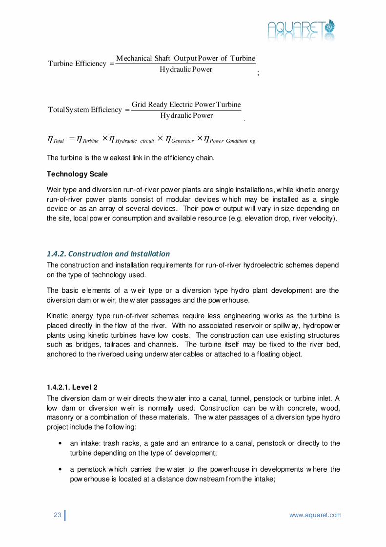
Plant efficiency
To quantify the technical performance of the run-of-river hydropow er technology, the
eff iciency of the system can be better understood. Of importance are the eff iciency of the
turbine, gearing, bearings, generator, electric pow er conditioning system and pow er
transmission system. This can be represented as follow s:
23 www.aquaret.com
Power Hydraulic
TurbineofPowerOutputShaftMechanicalEfficiencyTurbine =
;
Power Hydraulic
TurbinePower ElectricReady GridEfficiencySystem Total =
.
ngConditioniPowerGeneratorcircuitHydraulicTurbineTotal ηηηηη ×××=
The turbine is the w eakest link in the eff iciency chain.
Technology Scale
Weir type and diversion run-of-river power plants are single installations, w hile kinetic energy
run-of-river power plants consist of modular devices w hich may be installed as a single
device or as an array of several devices. Their pow er output w ill vary in size depending on
the site, local pow er consumption and available resource (e.g. elevation drop, river velocity).
1.4.2. Construction and Installation
The construction and installation requirements for run-of-river hydroelectric schemes depend
on the type of technology used.
The basic elements of a w eir type or a diversion type hydro plant development are the
diversion dam or w eir, the w ater passages and the pow erhouse.
Kinetic energy type run-of-river schemes require less engineering w orks as the turbine is
placed directly in the f low of the river. With no associated reservoir or spillw ay, hydropow er
plants using kinetic turbines have low costs. The construction can use existing structures
such as bridges, tailraces and channels. The turbine itself may be f ixed to the river bed,
anchored to the riverbed using underw ater cables or attached to a f loating object.
1.4.2.1. Level 2
The diversion dam or w eir directs the w ater into a canal, tunnel, penstock or turbine inlet. A
low dam or diversion w eir is normally used. Construction can be w ith concrete, wood,
masonry or a combination of these materials. The w ater passages of a diversion type hydro
project include the follow ing:
• an intake: trash racks, a gate and an entrance to a canal, penstock or directly to the
turbine depending on the type of development;
• a penstock which carries the w ater to the powerhouse in developments w here the
pow erhouse is located at a distance dow nstream from the intake;

24 www.aquaret.com
• the entrance and exit of the turbine w hich include the valves and gates necessary to
shut off f low to the turbine for shut-dow n and maintenance;
• a tailrace w hich carries the water from the turbine exit back to the river.
The pow erhouse contains the turbine or turbines and most of the mechanical and electrical
equipment.
1.4.3. Operation and Management
Operation
For conventional hydroelectric pow er stations, a major aspect of the management is the
integration of the electrical supply w ith the electricity grid. Conventional hydroelectric pow er
stations are able to increase or decrease their output depending on the demand w hich varies
over the day, w eek and year. Because run-of-river schemes have little to no storage there is
less scope to match the output w ith demand. Run-of-river schemes w ith small dams may be
able, at most, to allow the daily regulation of f lows, while diversion type and kinetic energy
type schemes w ill operate w hen the resource is available.
Maintenance
The technology used by diversion and w eir type run-of-river hydroelectric schemes is the
same as for conventional hydroelectric pow er stations so the maintenance of this mature
technology is w ell understood. For all three types of run-of-river technology there will be
routine maintenance of the turbine and equipment used in the pow er house. There should
also be routine inspection of the civil w orks (i.e. the anchoring system for kinetic energy type,
the dam/w eir, penstock and tailrace, trash racks, valves and gates). Where there is a dam
or w eir, as w ith any dam, accumulations of silt are very likely to occur w hich may need to be
dredged periodically.
1.4.3.1. Level 2
Survivability
The survivability of the components w ill depend on the type of technology used. Damage to
civil w orks by earthquake or erosion w ill be important for diversion and w eir type run-of-river
hydroelectric schemes. Erosion of the river bed around the anchoring system for kinetic type
hydroelectric schemes can also be an issue. For all three technologies, it w ill be important
to protect the turbines from damage from suspended solids in w ater, ice segments, logs and
other debris. A trash rack can be mounted upstream the turbines or around the turbine, like
a cage, in order to protect the turbines from damage. Kinetic energy type schemes are
particularly vulnerable to damage by large items of debris, and in certain cases (e.g. during
times of heavy f lood), it may be necessary to remove the turbines from the w ater. The risk
of collision w ith ships may be an important issue for kinetic energy type schemes on certain
rivers.

25 www.aquaret.com
Monitoring and automation
Automation of operation, maintenance and survivability may be economically beneficial
depending on the size of the scheme.
1.4.4. Decommissioning
Conventional hydroelectric pow er plants have many decommissioning costs w hich depend
on the capacity (kW) of the hydro plant. For this reason, a hydro plant of MW capacity w ill be
refurbished not decommissioned. The cost of decommissioning w ill depend on the civil
works that have to be dismantled. Kinetic energy type hydroelectric plants do not require
signif icant civil w orks, low ering the cost of decommissioning.
Life cycle
The life cycle of the dam is 60 years; with water passages, the intake has a life cycle of 50
years; the canal made from local materials has a life cycle of 30 years, and if it is reinforced
with concrete, w ill be 60 years; the tunnel and/or penstock made from steel w ill have a life
cycle of 40 years, and the tailrace w ill be 40 years; the hydraulic turbine w ill have a life cycle
of 22 years; the generator rotor w ill be 28 years; transmission lines w ith aerial on w ood
made pillar w ill be 12 years, aerial on metallic pillar w ill be 40 years, and bur ied lines w ill be
20 years.
1.5. Economical Factors
The unit costs of small hydro plants vary, w ith the largest factors being the civil w orks
required, the head/volume flow conditions, and the rated pow er of the turbine.
• Civil w orks are site specif ic, giving variation to unit cost estimates
• Sites w ith low heads and high f lows require a greater capital outlay, as larger civil
engineering w orks and turbine machinery w ill be needed to handle the larger f low of
water
• Unit costs rise together w ith the decrease of the rated pow er, due to economies of
scale
Making use of existing w eirs, dams, storage reservoirs and ponds can signif icantly reduce
both environmental impact and costs.
Typical ranges are 1000 – 4500 €/kW in EU countries, and 850 – 3800 €/kW in Eastern
European countries. In Germany, for example, the total cost of a new small hydropow er
plant is betw een 5000 - 9000 Euro/kW and are divided in most cases 35% civil construction -
50% electricity parts - 15% other.
Annual operation and maintenance costs are typically 2% of capital costs.

26 www.aquaret.com
1.5.1. Level 2
Since the technology used for diversion and w eir type run-of-river hydroelectric schemes is
mature, there is litt le scope for cost reduction.
Kinetic hydropow er is a new technology and there is some scope for future cost reductions.
Verdant Pow er, an American kinetic hydropow er development, estimates costs of $4,000
(€3100) per kW for a 5MW system. They estimate that by 2010 they can drive the cost dow n
to $2,500 (€1900) per kW through optimisation of the technology and commercial economics
of scale [2].
1.6. Environmental Interactions
Run-of-river developments w ill interact with the surrounding environment. Some interactions
may be positive; they may help to combat global w arming and create new jobs. Some may
have potentially negative outcomes such as alteration to river habitats, disrupting f ish
migration routes, and impeding boat navigation.
Good planning and operation w ill identify, reduce and mitigate negative impacts and
maximize positive interactions.
A general matrix of the potential key environmental interactions can be found on the
follow ing pages.

Potential key interactions between run-of-river energy installations and the receiving environment
27 www.aquaret.com
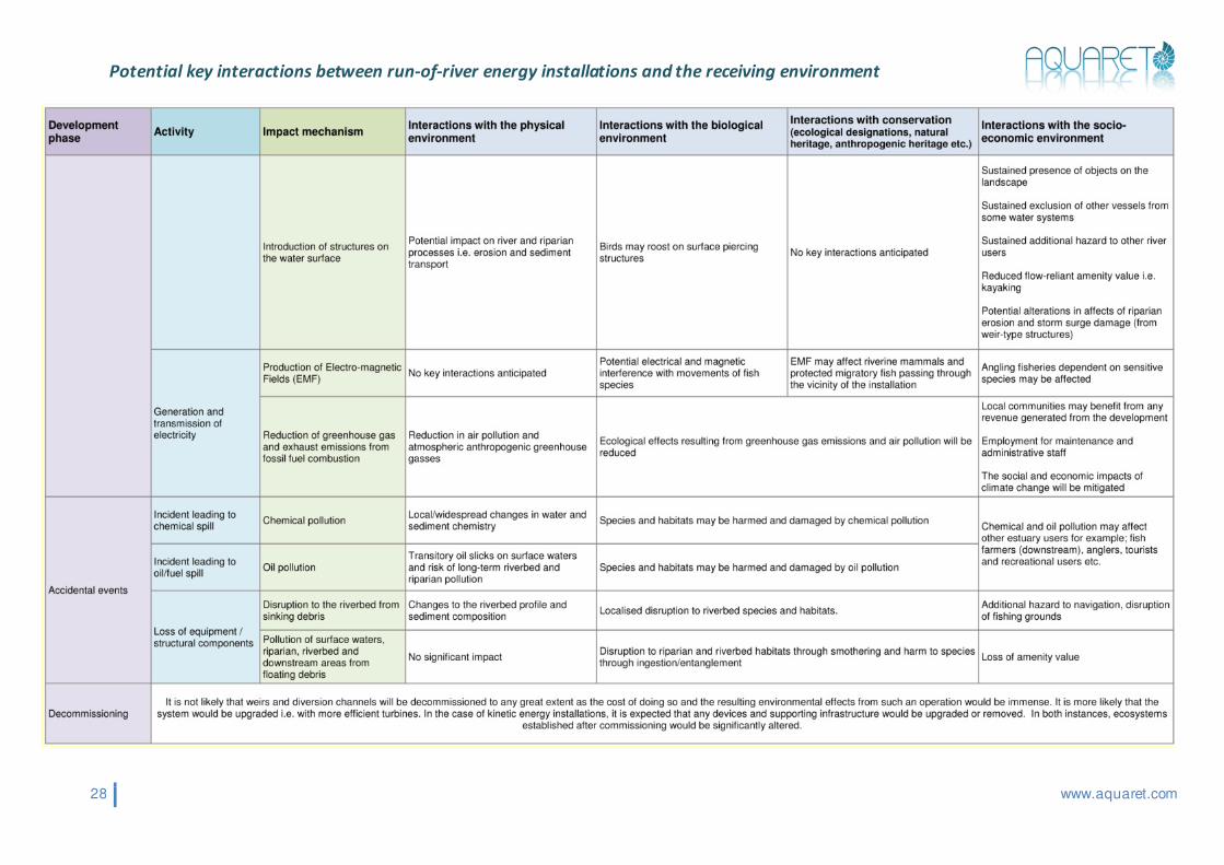
Potential key interactions between run-of-river energy installations and the receiving environment
28 www.aquaret.com

29 www.aquaret.com
1.7. Future Potential
Hydropow er is a mature technology and has been extensively deployed throughout Europe.
There may still be signif icant untapped potential. According to the RES EU Export Master
plan 2002 untapped potential may be 250 TWh/year, corresponding to 55 GW installed
capacity [3]. In 2004, the economically feasible potential for small hydro, of which most will
be run-of-river type, amounts to 20 TWh/year in the EU-15 States and 27 TWh/year in the
New Member States and Candidate Countries [4].
1.7.1. Level 2
Whether the potential capacity is developed w ill depend on several factors. The economic
incentives w ill depend on the capital cost and the price at which the energy can be sold, as
well as any other incentive schemes. These may include green certif icates, f iscal measures
such as tax rebates, and cost factors such as affordable access to grid connection. The
planning control in each country w ill be different; it w ill have an impact on the development of
potential sites and w ill be influenced by environmental impacts on the natural and human
environment.
1.8. Case Studies
In the Case Study section, SHP from Europe w as presented, starting w ith one of the f irst
types, dating from 1850, to some new ones. A kinetic river energy hydropower is also
presented.
30 www.aquaret.com
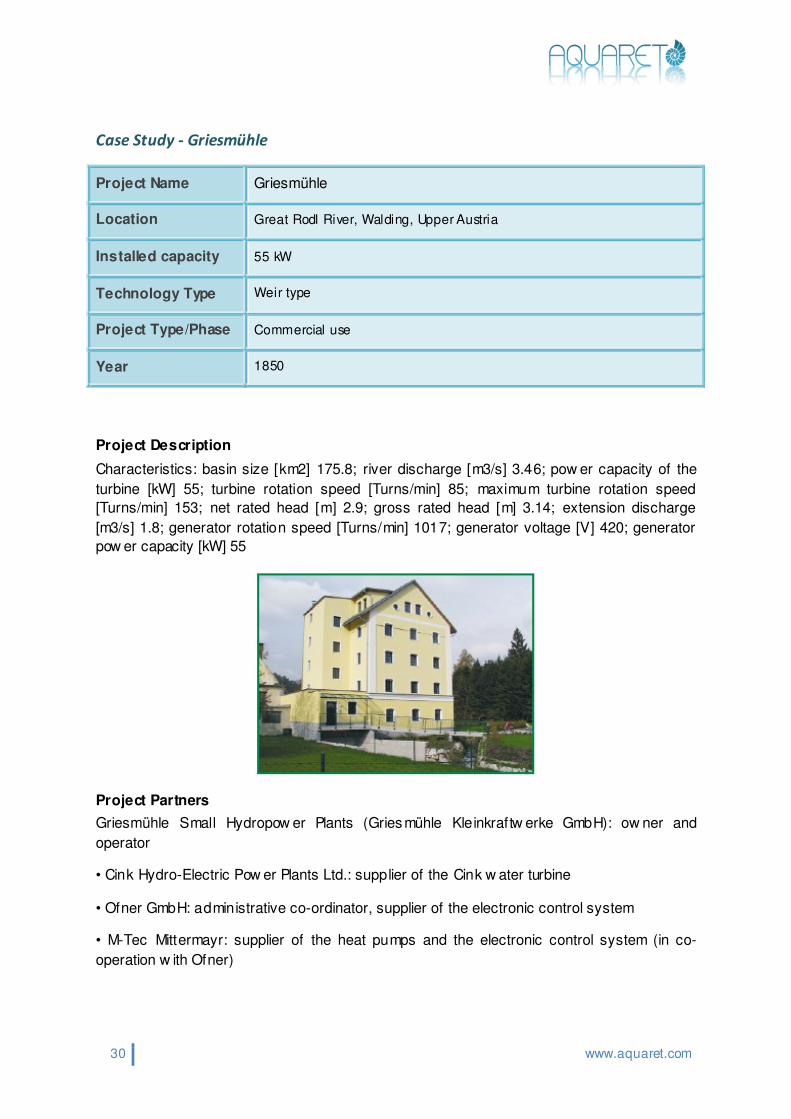
Case Study - Griesmühle
Project Description
Characteristics: basin size [km2] 175.8; river discharge [m3/s] 3.46; pow er capacity of the
turbine [kW] 55; turbine rotation speed [Turns/min] 85; maximum turbine rotation speed
[Turns/min] 153; net rated head [m] 2.9; gross rated head [m] 3.14; extension discharge
[m3/s] 1.8; generator rotation speed [Turns/min] 1017; generator voltage [V] 420; generator
pow er capacity [kW] 55
Project Partners
Griesmühle Small Hydropow er Plants (Griesmühle Kleinkraftw erke GmbH): ow ner and
operator
• Cink Hydro-Electric Pow er Plants Ltd.: supplier of the Cink w ater turbine
• Ofner GmbH: administrative co-ordinator, supplier of the electronic control system
• M-Tec Mittermayr: supplier of the heat pumps and the electronic control system (in co-
operation w ith Ofner)
Project Name Griesmühle
Location Great Rodl River, Walding, Upper Austria
Installed capacity 55 kW
Technology Type Weir type
Project Type/Phase Commercial use
Year 1850

31 www.aquaret.com
Cost and Financing
The total investment w as approximately €1M; restoration of the hydropow er plant cost
approximately €300,000, of w hich €230,000 w as f inanced by Griesmühle Small Pow er
Plants. The Austrian Municipal Credit Bank contributed the balance. The low -energy house
cost €700,000. This w as f inanced by Mr. Priesner (private capital), w ith support of the
Building Subsidy regulation (Wohnbauförderung) of the federal state of Upper Austria.
Further Information
Griesmühle Kleinkraftw erk GmbH, Mr. Kurt Priesner, Marktplatz 18, 4100 Ottensheim,
Austria, +43 0664 1226370, Fax: +43 7234 83310
Nanolytics, Kurt Schilcher, Sechterberg 64, 4101 Feldkirchen, Austria, +43 7233 6345,
Mobile phone: 0043 699 10047042, Fax: +43 7233 6640, nanolytics.schilcher@netw ay.at

32 www.aquaret.com
Case Study - Anatoliki
Project Description
The Operational Programme for Energy (OPE) is a large fund, administered by the EU and
the Greek State. In the f irst call for proposals, under Measure 3.2 of OPE ( Investments for
Renew able Energy Sources applications), six small hydro projects w ere selected for
f inancing, from a total of 11 proposals, w ith a total installed capacity of 7.85 MW.
One of the six plants w as the Small Hydro Plant in Anatoliki, in the prefecture of Ioannina, in
the Epirus Region. The proposal w as for a small hydroelectric plant w ith an installed
capacity of 700 kW, a nominal discharge of 460 lt/sec and a gross head of approximately
210 m. The length of the penstock w as 1.6 km, w ith an inner diameter of 600 mm. The
generating set consists of a Pelton-2 turbine and a synchronous generator.
Results
The construction of the SHP w as completed in 1999. Delays w ere due to w eather conditions
(mountainous terrain, inclement w eather) and construction of the line for connecting the
plant to the national grid. The target of the SHP, and the OPE as a w hole, is the production
of electricity from RES and the substitution of fossil fuels. The investments w ere evaluated
proportionally to the total annual energy produced, or to the amount of fossil fuel substitution.
The energy target of the SHP of Anatoliki w as the production of 4 GWh annually.
Potential for Replication
Hundreds of applications have been made in the framew ork of the OPE and 150 licenses
approved and granted for pow er generation projects involving small hydroelectric plants.
CRES has been granted such a license. Tw enty similar projects are due to begin in the
future.
Project Name Anatoliki
Location Anatoliki, prefecture of Ioannina, the Epirus Region, Greece
Installed capacity 700 kW
Technology Type Pelton-2 turbine, synchronous generator
Project Type/Phase Commercial use
Year 1999

33 www.aquaret.com
Project Partners
'Ipirotiki Energiaki S.A.', and CRES (Small Hydro Department).
Cost and Financing
The total cost of the plant w as estimated at €1.03M.
The capital subsidy w as 45% of the total investment cost, approximately €0.46 billion.
The budget for equipment, softw are, materials, transport and installat ion is no less than 85%
of the total budget. There is a ceiling on the percentage of the auxiliary costs in the total
budget, at no more than 15% of the total budget.
Further Information
CRES, Small Hydro Department, 19th km Marathonos Ave. 19009, Pikermi, Greece
Kostas Vasilikos, + 3010 6603282, [email protected]

34 www.aquaret.com
Case Study - Herrenhausen
Project Description
The small hydropow er station at Herrenhausen uses an average head of 2.10m to generate
electricity. The head varies with the water level in the river, w hich can be 3.50m in summer.
When the w ater is high (~30 days per year) no electricity can be produced because the head
is too small. The plant is equipped w ith tw o running w ater Kaplan turbines w ith an electrical
pow er capacity of 470kW each. The turbines have a diameter of 1.95 m. The total w ater f low
varies betw een 16m3/s (low water) and 250m3/s (high w ater). The hydropow er station w as
designed for the average f low in the river Leine of 50 m3/s. The maximum overall turbine
eff iciency of the hydropower station is 92.3% and the transmission and generator can
achieve an eff iciency of 94.5%. The overall utilisation factor of the plant varies betw een 86%
and 92.5%.
The plant has been f itted w ith a f ish ladder enabling f ish to sw im upstream past the w eir. The
ladder consists of 25 basins, betw een which f ish can sw im. A grille has been f itted across
the front of the turbine inlet to prevent f ish from being draw n into the turbine.
Project Name Herrenhausen
Location River Leine, Hanover, Germany
Installed capacity 940 kW
Technology Type Weir type plant, two running water Kaplan turbines
Project Type/Phase Commercial use
Year 1999

35 www.aquaret.com
Project Partners
The city of Hanover, Municipal Services of Hanover (Stadtw erke Hanover AG): operator and
ow ner of the plant; Naturstrom AG: supplier of electricity from renew able energy sources;
Expo 2000 GmbH: f inancial aid; ProKlima: environmental protection fund, f inancial aid.
Cost and Financing
The total investment in the hydroelectric station w as approximately €5.1M, of w hich €3M w as
for construction. The turbine cost approximately €1M. The balance w as used for generators,
planning and licence. The environmental compatibility study, including the compensation and
replacement measures, cost approximately €100,000. Operation and maintenance costs for
the project are €51,000 a year. The plant w as f inanced by the Municipal Services of
Hanover, w ith €409,000 from Expo 2000. ProKlima, the local climate-protection fund,
granted €971,000. The State of Low er Saxony has granted a low-interest loan for 50% of the
investment.
Further Information
Stadtw erke Hannover AG, Mr. Christoph Kollenda, PO Box 5747, 30057 Hanover, Germany,
+49 511 430 36 23, Fax: +49 511 430 36 87, [email protected],
www.enercity.de

36 www.aquaret.com
Case Study - Giurgiu
Project Description
The Energetically Autonomous River Buoy is a buoy which provides a light pow ered by a
hydro generator for river navigation. The hydro generator has an axial propeller placed in
free water current f low or in a shrouded body. The propeller transforms the kinetic energy of
water into mechanical energy and the electric generator transforms the mechanical energy
into electric energy. The propeller diameter is 0.5 m and for river speeds of 0.5 m/s to 2 m/s
the pow er of the hydro generator varies between 6.4 W to 0.40 kW. Energetically
Autonomous River Buoy w ith Bright Signaling w as designed by a joint team ( ICPE-CA,
www.icpe-ca.ro, National Institute for R&D in Electrical Engineering and UPB –
www.hydrop.pub.ro) and commissioned in 2003 in Giurgiu, on Danube River.
Testing the prototype
of hydro generator
Energetically
Autonomous River Buoy
with Bright Lighting,
Danube River 2003
Project Name Energetically Autonomous River Buoy
Location Giurgiu, Danube River, Romania
Installed capacity 0.4kW
Technology Type Kinetic energy
Project Type/Phase Commercial use
Year 2003

37 www.aquaret.com
1.9. Test Your Knowledge
Learning Outcomes – Run-of-River
1 Basic – Equivalent to EQF (European Qualif ication Framew ork) Level1 and Bloom’s Taxonomy “Know ledge” category. This level requires the student to have basic general know ledge of the subject, be able to recall important information.
Intermediate – Equivalent to EQF level 2 and Bloom’s Taxonomy “Comprehension”
category. This level requires the student to be able to explain basic factual know ledge.
Level Run-of-River
Ba
sic
1
On successful completion of this module you w ill be able to:
• Understand the basic physical processes that result in the w ater cycle • Recognise that that the movement of w ater associated w ith rivers is a renewable
resource • Recognise that run of river resources are w idely but not evenly distributed across
Europe and that local geographical features and climate affect the resource level • Recall the different technology types used to extract energy from river systems
• Identify the different project phases such as Design and Planning, Construction and Installat ion, Operation and Management, and Decommissioning
• Understand the importance of taking into consideration of all these project phases when evaluating the impacts and feasibility of a particular development
• Explain how energy extraction leads to a number of possible interactions (both negative and posit ive) w ith the surrounding environment
• Understand that the surrounding environment includes physical processes, wildlife and habitats, conservation interests, communities and social features, as well as commerce and economic activit ies
• Outline how negative impacts can be minimised
• Name specif ic examples w here run-of-river hydro energy is being extracted
Inte
rmed
iate
On successful completion of this module you w ill be able to:
• Describe a few key developments in the use of hydro energy
• Describe the hydrological cycle • Identify w hich areas have high resources in terms of geographical features and
climate
• Explain w hy different areas favour the different run of river technologies • Describe the different technology types used to extract energy from river systems
• Outline the important factors in each phase of the project • Outline the key types of environmental interactions associated w ith Run-of River
developments • Explain how these may change through a project lifecycle, in different locations
and at different times • Outline some of the factors w hich influence the overall cost of the project for the
different technologies • Name examples w here run-of-river hydro energy is being extracted
38 www.aquaret.com
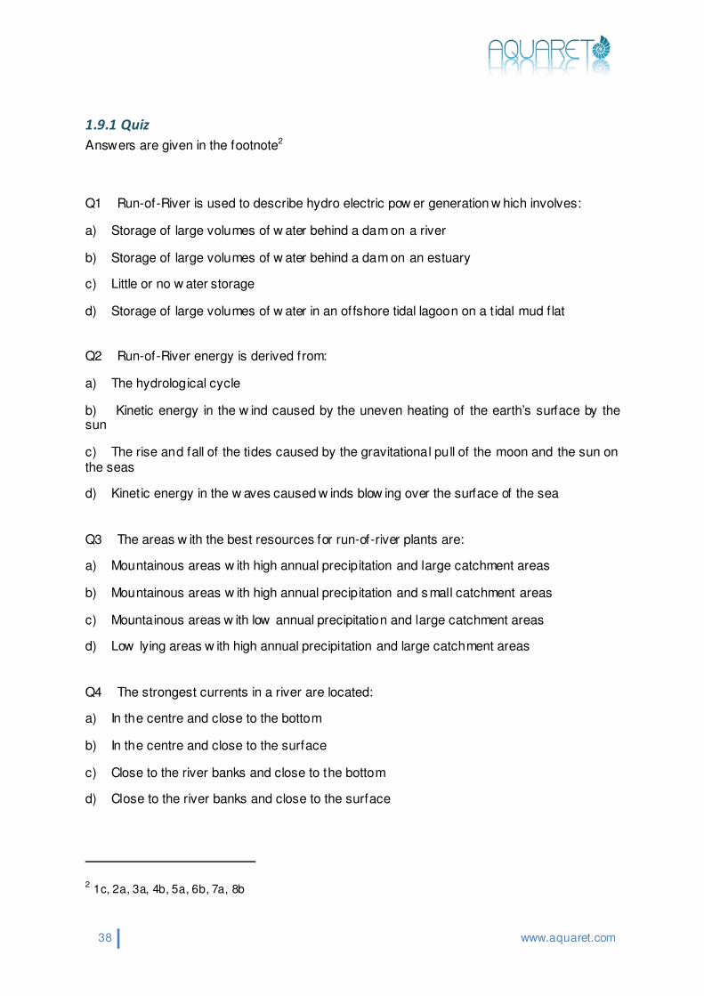
1.9.1 Quiz
Answers are given in the footnote2
Q1 Run-of-River is used to describe hydro electric pow er generation w hich involves:
a) Storage of large volumes of w ater behind a dam on a river
b) Storage of large volumes of w ater behind a dam on an estuary
c) Little or no w ater storage
d) Storage of large volumes of w ater in an offshore tidal lagoon on a t idal mud f lat
Q2 Run-of-River energy is derived from:
a) The hydrological cycle
b) Kinetic energy in the w ind caused by the uneven heating of the earth’s surface by the sun
c) The rise and fall of the tides caused by the gravitational pull of the moon and the sun on the seas
d) Kinetic energy in the w aves caused w inds blow ing over the surface of the sea
Q3 The areas w ith the best resources for run-of-river plants are:
a) Mountainous areas w ith high annual precipitation and large catchment areas
b) Mountainous areas w ith high annual precipitation and small catchment areas
c) Mountainous areas w ith low annual precipitation and large catchment areas
d) Low lying areas w ith high annual precipitation and large catchment areas
Q4 The strongest currents in a river are located:
a) In the centre and close to the bottom
b) In the centre and close to the surface
c) Close to the river banks and close to the bottom
d) Close to the river banks and close to the surface
2 1c, 2a, 3a, 4b, 5a, 6b, 7a, 8b

39 www.aquaret.com
Q5 The follow ing are types of run-of-river technology
a) Weir type plant, diversion type plant, kinetic energy devices
b) Attenuators, point absorbers, overtopping devices
c) Offshore tidal lagoons and tidal barrages
d) Horizontal and vertical axis w ind turbines
Q6 A diversion type plant is one w hich:
a) Water is dammed w ith a low dam or w eir to create a small reservoir and head of w ater.
b) A portion of the river is channelled through a canal or penstock (i.e. a pipe), to carry the water from the intake to the pow erhouse where the turbines are located
c) The devices are installed directly into f low ing w ater to capture the kinetic energy
d) Has an arm w hich pivots back and forth like an inverted pendulum due to the movement of the w ater particles in the w aves
Q7 The follow ing is an example of w here run-of-river hydro energy is being extracted:
a) Anatoliki, Greece using a 700kW “Pelton-2” turbine
b) Yell Sound, Shetland Islands, Scotland device using a 150kW reciprocating hydroplane device
c) Aguçadoura, Northern Portugal device using a 3 x 750kW Floating articulated attenuators
d) Scroby Sands, England using 30 x 2MW horizontal axis turbines
Q8 The follow ing is an impact associated w ith extraction of run-of-river hydro energy:
a) Reduced w ave action leading to potential changes in intertidal and sublittoral habitats
b) Changes in river f low patterns leading to potential disruption to protected migratory f ish routes
c) Reduction on t idal current energy leading to potential increase in sediment settlement dow nstream of the device
d) Risk of bird collisions w ith moving turbine blades

40 www.aquaret.com
1.10. Further Information
Bibliography
[1] Lehner, B., Henrichs, T., Döll, P., Alcamo, J. (2001): EuroWasser – Model-based
assessment of European water resources and hydrology in the face of global change.
Kassel World Water Series 5, Center for Environmental Systems Research, University of
Kassel, Kurt-Wolters-Strasse 3, 34109 Kassel, Germany.
[2] U.S. Department of Energy, OFFICE OF ENERGY EFFICIENCY AND RENEWABLE
ENERGY, Wind and Hydropow er Technologies Program (2006) Proceedings of the
Hydrokinetic and Wave Energy Technologies Technical and Environmental Issues
Workshop [online]
http://hydropow er.inl.gov/hydrokinetic_w ave/pdfs/hydro_workshop_proceedings.pdf
[3] ESHA. (2008). SHP in Europe. Retrieved 07/11/08, from European Small Hydropow er
Association: http://www.esha.be/index.php?id=43
[4] ESHA. (2004). State of the Art of SHP in EU-25. [online].
http://www.erec.org/f ileadmin/erec_docs/Documents/Publications/Brochure_ESHA_24_01_0
6_FINAL.pdf
Further reading
For more information on small hydro pow er see http://www.esha.be/
For an overview of today’s hydropower utilization in Europe see Lehner, B., Henrichs, T.,
Döll, P., Alcamo, J. (2001): EuroWasser – Model-based assessment of European water
resources and hydrology in the face of global change. Kassel World Water Series 5,
Center for Environmental Systems Research, University of Kassel, Kurt-Wolters-Strasse 3,
34109 Kassel, Germany.