Embed Size (px)
Citation preview

11
Project Planning
Faculty of Applied Engineering and Urban Planning
Civil Engineering Department
Week 4
2nd Semester 2008/2009
UP Copyrights 2008
Const
ruct
ion P
roje
ct
Managem
ent
Eng: Eyad Haddad

22
Chapter 3: Project PlanningChapter 3: Project Planning
3.1 Introduction
Planning is a general term that sets a clear road map that
should be followed to reach a destination.
Planning involves the breakdown of the project into
definable, measurable, and identifiable tasks/activities, and
then establishes the logical interdependences among them.
planning answers three main questions:
1. What is to be done?
2. How to do it?
3. Who does it?
33
Chapter 3: Project PlanningChapter 3: Project Planning
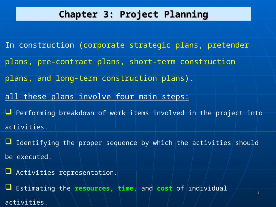
In construction (corporate strategic plans, pretender plans, pre-
contract plans, short-term construction plans, and long-term
construction plans).
all these plans involve four main steps:
Performing breakdown of work items involved in the project into activities.
Identifying the proper sequence by which the activities should be executed.
Activities representation.
Estimating the resources, time, and cost of individual activities.

44
The inputs and outputs of the planning process are shown in the following Figure
55
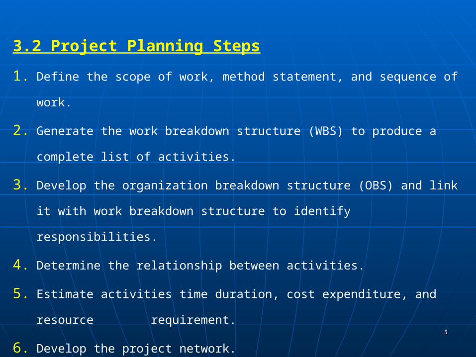
3.2 Project Planning Steps
1. Define the scope of work, method statement, and sequence of work.
2. Generate the work breakdown structure (WBS) to produce a complete
list of activities.
3. Develop the organization breakdown structure (OBS) and link it with
work breakdown structure to identify responsibilities.
4. Determine the relationship between activities.
5. Estimate activities time duration, cost expenditure, and resource
requirement.
6. Develop the project network.

66
3.2.1 Work breakdown structure (WBS)
WBS is designed to logically sub-divide all the work-elements of the
project into a graphical presentation.
The full scope of work for the project is placed at the top of the
diagram, and then sub-divided smaller elements of work at each lower
level of the breakdown.
At the lowest level of the WBS the elements of work is called a work
package.
The WBS will outline the scope of the project and the responsibility for
each work package.

77
Figure 3.3 shows another example for more detailed WBS, in which the
project WBS is divided into five levels

88

99
WBS and organizational breakdown structure (OBS)
WBS can be related to the contractor’s organizational
breakdown structure (OBS).
OBS defines the different responsibility levels and their
appropriate reporting needs as shown in Figure 3.5.
WBS coding
A project code system provides the framework for project planning
and control in which each work package in a WBS is given a unique code
that is used in project planning and control.
An example of this coding system is the Master Format (Figure 3.6)

1010

1111

1212
Figure 3.7 shows an example of the coding system using a standardize
system as the Master Format.

1313
Figure 3.7 shows an example of the coding system using a standardize system as the Master Format.
The Master format is divided into 16 divisions as follows:
DescriptionDescriptionDescriptionDescription
11General RequirementsGeneral Requirements99FinishesFinishes
22Site workSite work1010SpecialtiesSpecialties
33ConcreteConcrete1111EquipmentEquipment
44MasonryMasonry1212FurnishingsFurnishings
55MetalsMetals..1313Special ConstructionSpecial Construction
66Woods & PlasticsWoods & Plastics1414Conveying SystemsConveying Systems
77Thermal & MoistureThermal & Moisture
ProtectionProtection1515MechanicalMechanical
88Doors & WindowsDoors & Windows1616ElectricalElectrical

1414
Project activities
1. Production activities have a certain quantity of work, resource needs, costs, and duration.
Examples: (excavation, formwork, reinforcement, concreting, etc)
2. Procurement activities
For specifying the time for procuring materials or equipment that are
needed for a production activity.
Examples: (brick procurement, boiler manufacturing and delivery, etc.)
3. Management activities
It related to management decisions such as (approvals, vacations, etc.)

1515

1616
3.2.2 Activities relationships
The planning team needs to answer the following questions for each activity.
1. Which activities must be finished before the current one can start?
2. What activity (ies) may be constructed concurrently with the
current one?
3. What activity (ies) must follow the current one?

1717
Example 3.3:
Suppose that a project consists of nine different activities:
A. Site clearing (of brush and minor debris الحطام ,( إزالة
B. Removal of trees,
C. General excavation,
D. Grading general area,
E. Excavation for utility trenches,
F. Placing formwork and reinforcement for concrete,
G. Installing sewer lines,
H. Installing other utilities,
I. Pouring concrete.

1818
Example 3.3:
The result of our planning is the immediate precedence shown in Table 3.2.
1919
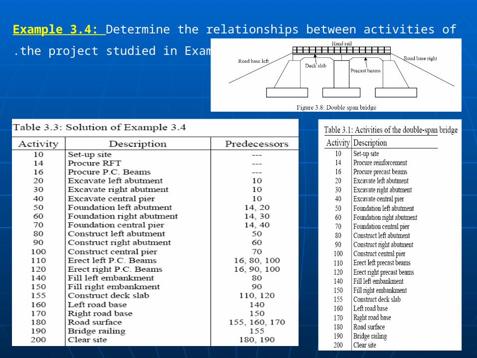
Example 3.4: Determine the relationships between activities of the
project studied in Example3.2.

2020
Logical relationship considering resource constraints:
Overlap or lag:
The absence of overlap means that the first activity must finish
before the second may start.
A positive overlap (+) تسريع means that accelerate the successor
(next) activity.
A negative overlap (-) تأخير means that retarded the successor
(next) activity.
تسري)(ع
تأخير))

2121
Example 3.5:
This case study is for a small 3 houses project. The main segments of a single house, the responsibilities, and the logical relationship are identified as follows:
- 11 work packages are involved: A and B (civil work, substructure), C, D,E, and F (civil work, superstructure), G (electrical, interior), H
( electrical, exterior ,)I )mechanical, HVAC(, J )mechanical, elevator(, and K )mechanical, plumbing(.
- Substructure is supervised by Ahmed (activity A), and Ali (activity B).
- Superstructure is supervised by Hossam (activities C and F) and Mona (activities D and E).
- All electrical work is supervised by George.
- HVAC and plumbing are supervised by Adam; elevator work is
supervised by Samy.
- Activities E and F follow activity B.
- Activity C precedes activity G.
- Activity I follows the completion of activity E .
- The predecessors to activity K are activities H and I.
- Activity D follows activity A and precedes activity H.
- Activity J is preceded by activities F and G.

2222
1 .Create a WBS and OBS chart?
-Activities E and F follow activity B.
- Activity C precedes activity G.
- Activity I follows the completion of activity E.
-The predecessors to activity K are activities H and I.
-Activity D follows activity A and precedes activity H.
-Activity J is preceded by activities F and G.

2323
1 .Create a WBS and OBS chart?

2424
Types of activities relationships:Types of activities relationships:
Four types of relationships can be defined as described and illustrated below
relationships are defined from the predecessor to the successor activity.
a) Finish to start (FS). The successor activity can begin only
when the current activity completes.b) Finish to finish (FF). The finish of the successor activity depends
on the finish of the current activity.
d) Start to finish (SF). The successor activity cannot finish until the
current activity starts.
c) Start to start (SS). The start of the successor activity depends
on the start of the current activity.

2525
3.2.3 Drawing the project network3.2.3 Drawing the project network
A project network is a set of arrows and nodes.
Before drawing the network, it is necessary to ensure that
The project has a unified starting and ending point.
The need for this start activity arises when there is more than
one activity in the project that has no predecessors and the
end activity is needed when there is more than one activity
that has no successors.
Networks should be continuous.

2626
Drawing the project networkDrawing the project network
Two ways used to draw a network diagram for a project:Two ways used to draw a network diagram for a project:
1. Activity on Arrow (AOAAOA) representation.
2. Activity on Node (AONAON) representation.

2727
1) Activity on arrow network (AOA)1) Activity on arrow network (AOA)The arrows represent activities while the nodes represent the start and the
end of an activity.
When one activity depends upon another, both appear on the diagram as
two arrows having a common node.

2828
Rules that need to be followed when constructing an AOA Rules that need to be followed when constructing an AOA
network diagram:network diagram:
Each activity must have a unique i – j numbers.
It is recommended to have a gap between numbers (5,10, etc.)
Avoid back arrows.
In some situations, when more than one arrow leave the same node and arrive at another node, dummy activities must be used.
The dummy activityThe dummy activity: zero duration, consumes no resources, drawn as dashed lines, and used to adjust the network diagram.

2929

3030
Comparison between AOA and AON
There are some differences between them:
1) There is no need for the use of dummy activities in AON
representation.
2) AON are more easily to draw and to read.
3) In AOA, an activity can only start when all its predecessors have
finished.
4) AON allows for overlap/lag representation.
5) AON allows for the representation of the four types of relationships
while AOA allows only for the finish to start relationship.

3131
A
G
F
Y
E
D
C
X
B
Figure3.16: AON Network For Example 3.6
3232
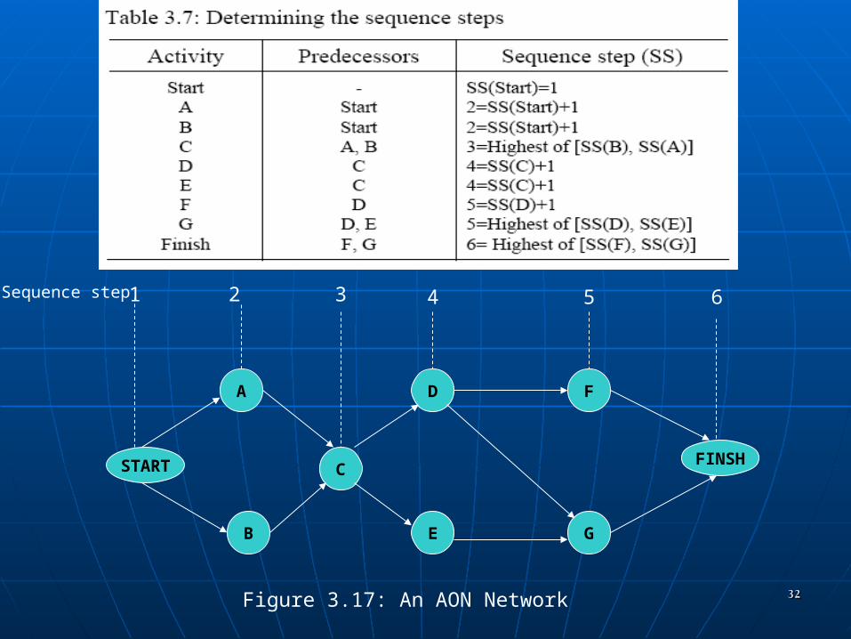
START
A
B
D
C
G
F
E
FINSH
1 32 64 5Sequence step
Figure 3.17: An AON Network

3333
Example 3.7:
Draw the AOA and AON networks for the project given in Example 3.5?.
1 .AOA and AON networks :
5 15 454030
20 35
2510A
B
C
D
E
F
G
H
I K
J
Figure 3.18: AOA networkFigure 3.18: AOA network

3434
Example 3.7:2 .AON networks for the project given in Example 3.5.
START B
C
A
I
J
H
E
G
D
F
K
Finish
Figure 3.19: AON networkFigure 3.19: AON network
ActivityPredecessorsSS
Start-
AStart
BStart
CStart
DA
EB
FB
GC
HD
IE
JF,G
KH,I
FinishJ,K
11
22
22
22
33
33
33
33
44
44
44
55
66
3535
Next LectureNext Lecture
Estimating Activity Duration and Estimating Activity Duration and Direct CostDirect Cost

3636
3.33.3 Estimating Activity Duration and Direct CostEstimating Activity Duration and Direct CostEach activity has associated time duration. These durations are used in preparing a schedule. For example .
suppose that the durations shown in Table 3.8 were estimated for a project. The entire set of activities would then require at least 3 days, sincethe activities follow one another directly and require a total of 1.0 + 0.5 + 0.5 + 1.0 = 3 days.
The duration of an activity may be estimated as:
Activity duration = quantity of work / number of crews x resource output