Embed Size (px)
Citation preview
1
Physics with a Vertex Detector at
the Linear Collider
Overview
• VXD at SLD at the Z0
• Physics at Higher Energy
• VXD for the ILC
Dave JacksonOxford University/RAL
Osaka University
September 2004
2
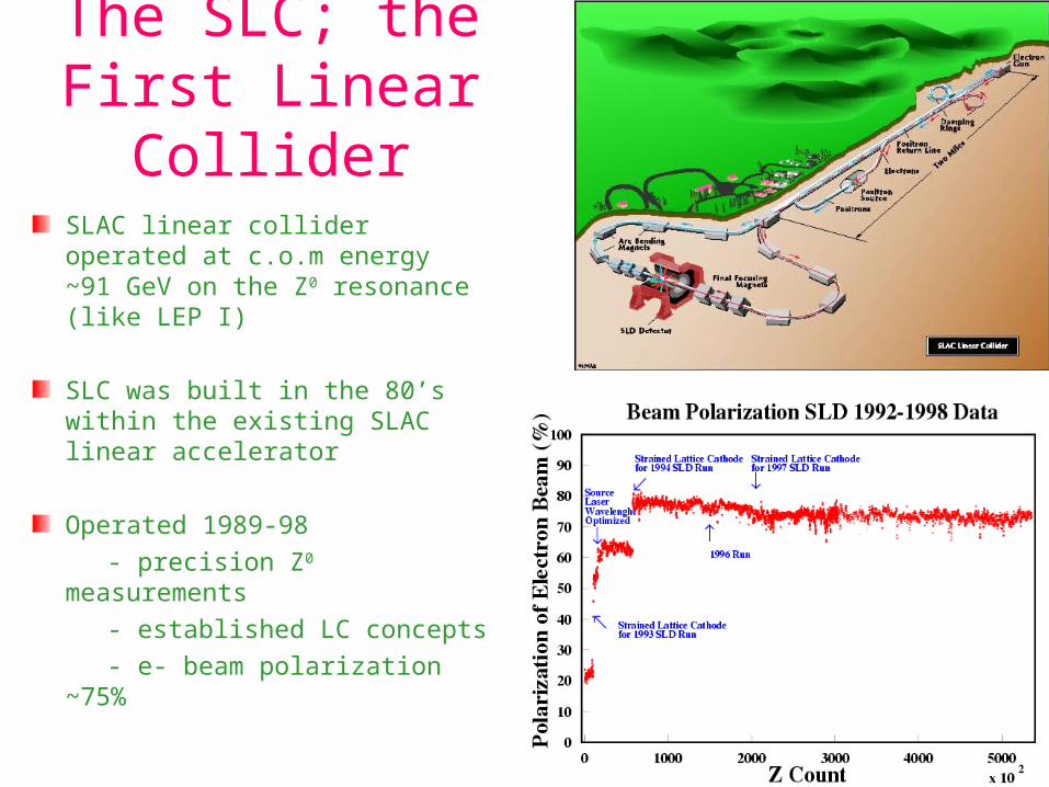
The SLC; the First Linear Collider
SLAC linear collider operated at c.o.m energy ~91 GeV on the Z0 resonance (like LEP I)
SLC was built in the 80’s within the existing SLAC linear accelerator
Operated 1989-98 - precision Z0 measurements - established LC concepts - e- beam polarization ~75%
3
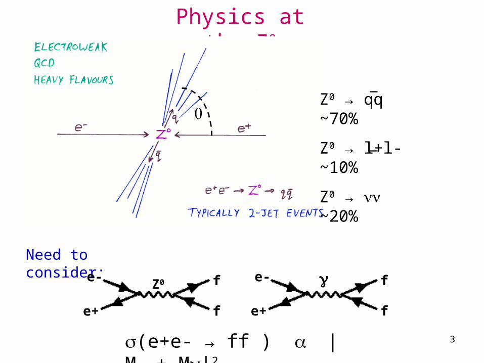
Physics at the Z0
Need to consider:
e-
e+
f
f
Z0 e-
e+ f
f
(e+e- → ff ) |MZ + M|2
Z0 → qq ~70%
Z0 → l+l- ~10%
Z0 → ~20%
4
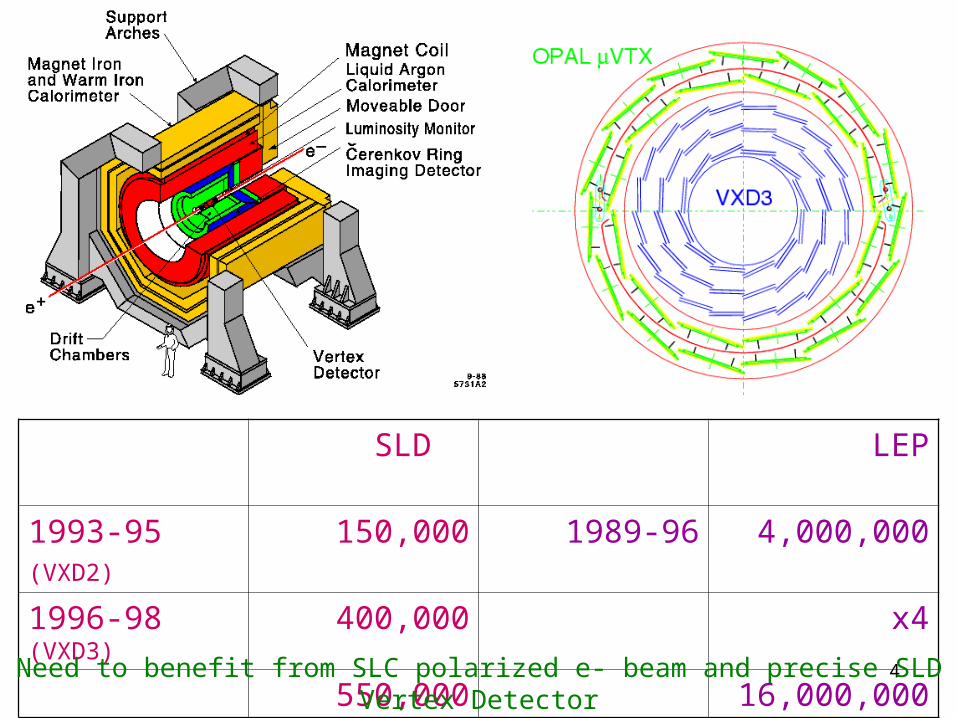
SLD LEP
1993-95 (VXD2)
150,000 1989-96 4,000,000
1996-98 (VXD3) 400,000 x4
550,000 16,000,000Need to benefit from SLC polarized e- beam and precise SLD Vertex Detector
5
6
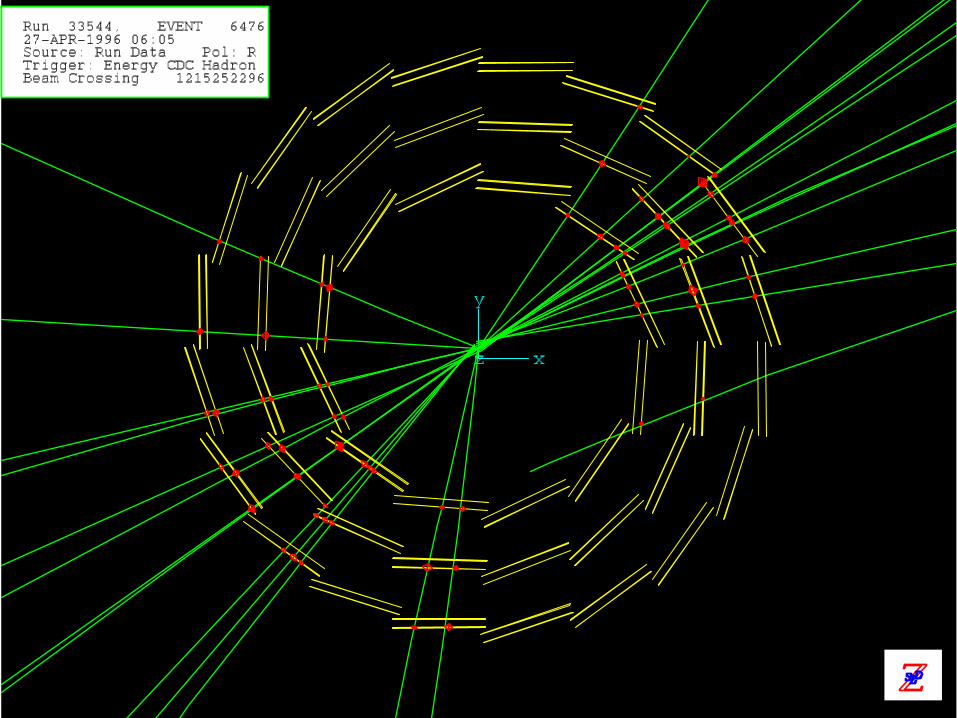
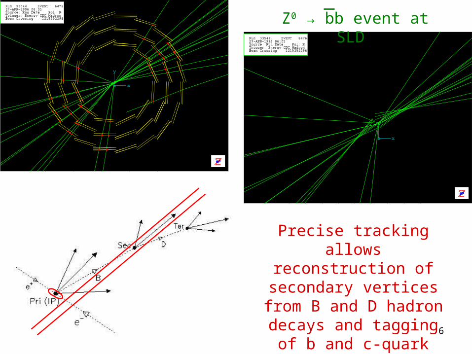
Z0 → bb event at SLD
Precise tracking allows reconstruction of
secondary vertices from B and D hadron
decays and tagging of b and c-quark flavoured jets
7
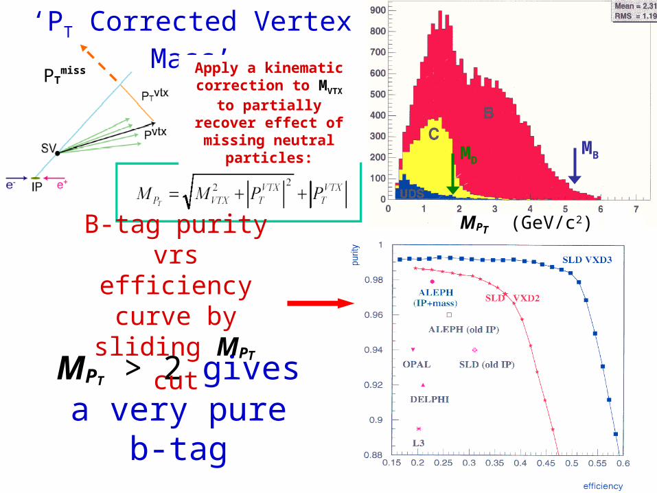
MPT > 2 gives a very pure b-tag
MPT (GeV/c2)
MBMD
‘PT Corrected Vertex Mass’
Apply a kinematic correction to MVTX to
partially recover effect of missing neutral
particles:
PTmiss
B-tag purity vrs efficiency curve
by sliding MPT cut
8
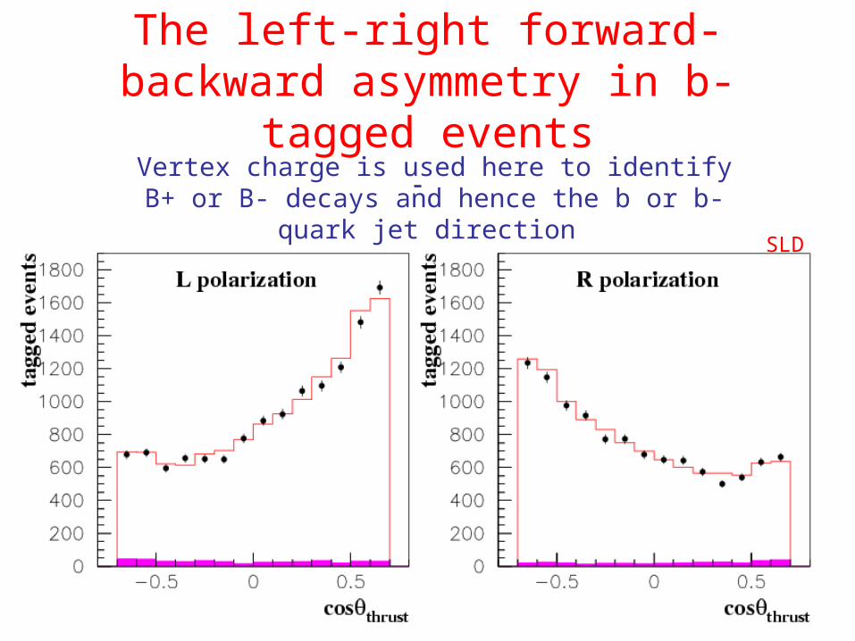
The left-right forward-backward asymmetry in b-tagged events
SLD
Vertex charge is used here to identify B+ or B- decays and hence the b or b-quark jet direction
9
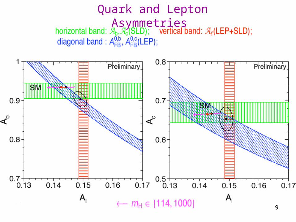
Quark and Lepton Asymmetries
10
11
12
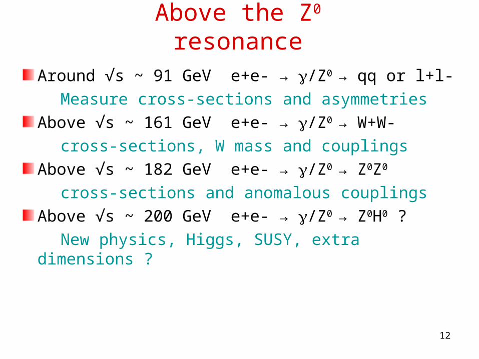
Above the Z0 resonance
Around √s ~ 91 GeV e+e- → /Z0 → qq or l+l-
Measure cross-sections and asymmetriesAbove √s ~ 161 GeV e+e- → /Z0 → W+W-
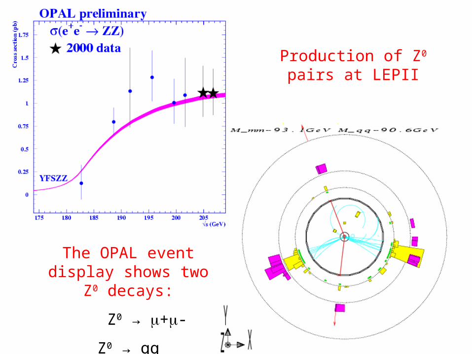
cross-sections, W mass and couplingsAbove √s ~ 182 GeV e+e- → /Z0 → Z0Z0
cross-sections and anomalous couplingsAbove √s ~ 200 GeV e+e- → /Z0 → Z0H0 ?
New physics, Higgs, SUSY, extra dimensions ?
13
Production of Z0 pairs at LEPII
The OPAL event display shows two Z0
decays:
Z0 → +-
Z0 → qq
14
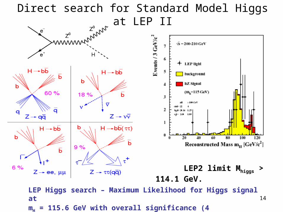
LEP2 limit Mhiggs > 114.1 GeV.
LEP Higgs search – Maximum Likelihood for Higgs signal at mH = 115.6 GeV with overall significance (4 experiments) ~ 2
Direct search for Standard Model Higgs at LEP II
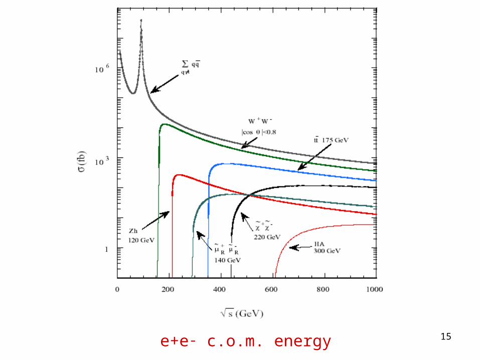
15e+e- c.o.m. energy
16
17
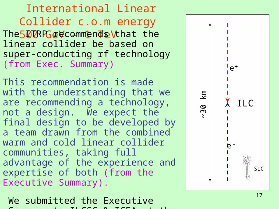
International Linear Collider c.o.m energy 500 GeV – 1 TeV
SLC
e+
e-
~3
0 km ILC
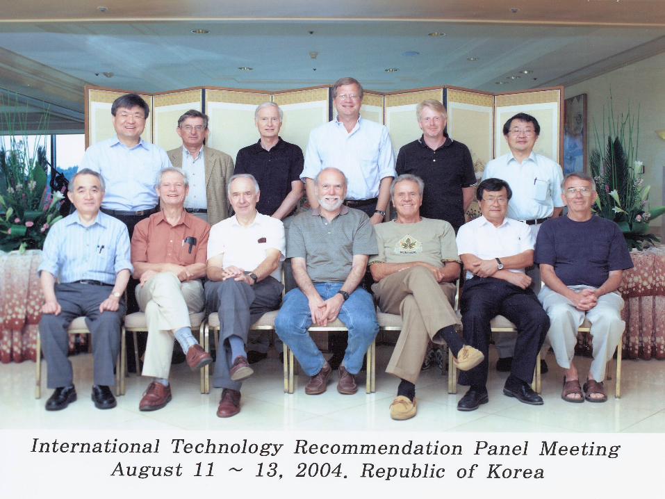
The ITRP recommends that the linear collider be based on super-conducting rf technology (from Exec. Summary)
This recommendation is made with the understanding that we are recommending a technology, not a design. We expect the final design to be developed by a team drawn from the combined warm and cold linear collider communities, taking full advantage of the experience and expertise of both (from the Executive Summary).
We submitted the Executive Summary to ILCSC & ICFA at the Beijing Conference
http://www.interactions.org/pdf/ITRPexec.pdf
18
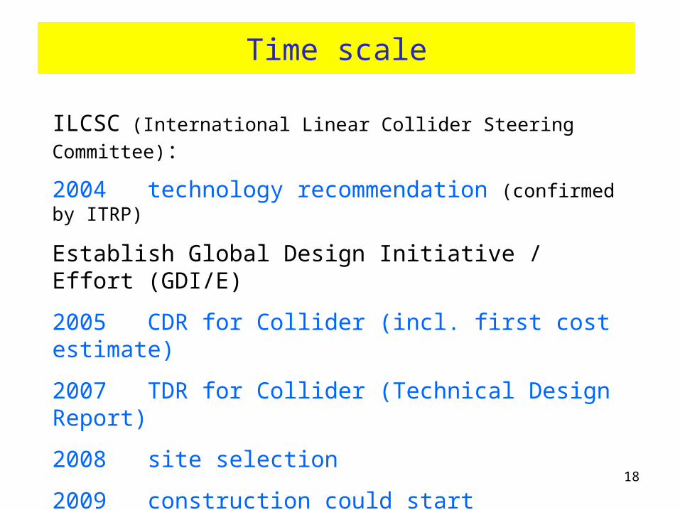
Time scale
ILCSC (International Linear Collider Steering Committee):
2004 technology recommendation (confirmed by ITRP)
Establish Global Design Initiative / Effort (GDI/E)
2005 CDR for Collider (incl. first cost estimate)
2007 TDR for Collider (Technical Design Report)
2008 site selection
2009 construction could start (need approval of funding but not yet major spending !)
2015 LC and Detector ready for Physics
19
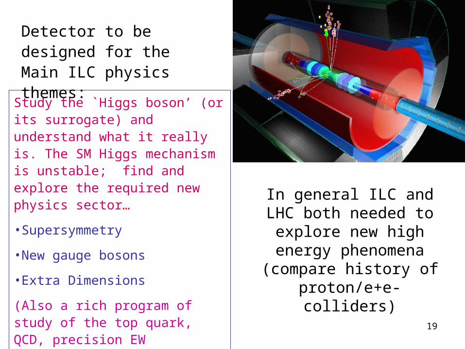
Study the `Higgs boson’ (or its surrogate) and understand what it really is. The SM Higgs mechanism is unstable; find and explore the required new physics sector…
•Supersymmetry
•New gauge bosons
•Extra Dimensions
(Also a rich program of study of the top quark, QCD, precision EW measurements, etc.)
Detector to be designed for the Main ILC physics themes:
In general ILC and LHC both needed to
explore new high energy phenomena (compare history of
proton/e+e- colliders)
20
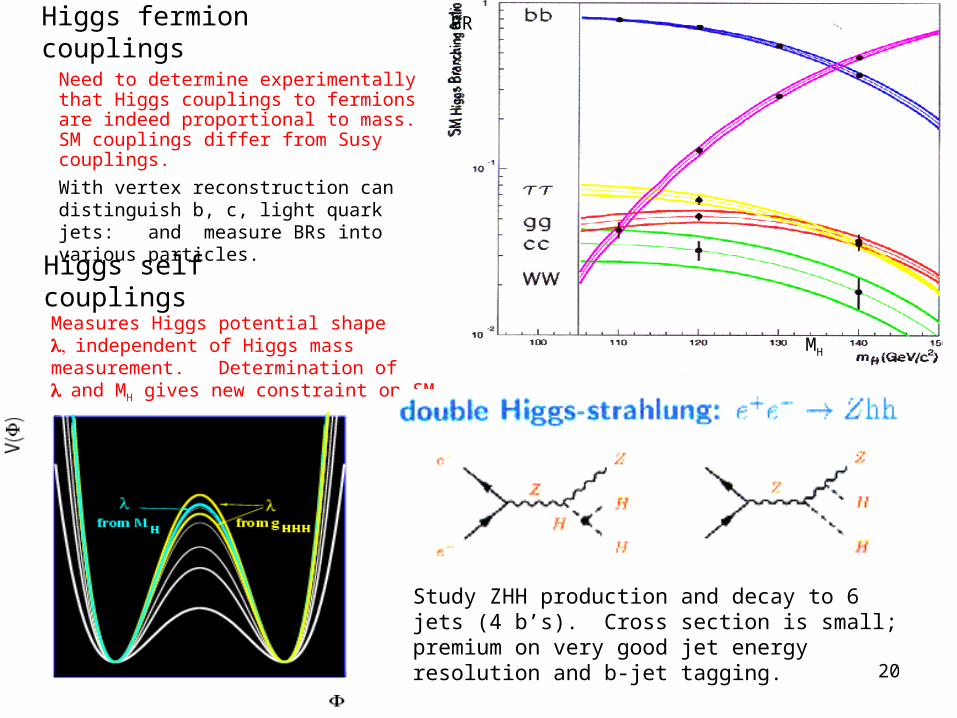
Need to determine experimentally that Higgs couplings to fermions are indeed proportional to mass. SM couplings differ from Susy couplings.
Higgs fermion couplings
With vertex reconstruction can distinguish b, c, light quark jets: and measure BRs into various particles.
BR
MH
Higgs self couplings
Measures Higgs potential shape independent of Higgs mass measurement. Determination of and MH gives new constraint on SM.
Study ZHH production and decay to 6 jets (4 b’s). Cross section is small; premium on very good jet energy resolution and b-jet tagging.
21
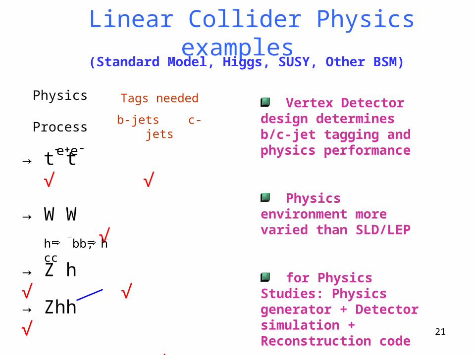
→ t t √ √
→ W W √
→ Z h √ √
→ Zhh √
SUSY CP √ √
AFB(Z/) √ √
h bb, h cc
Linear Collider Physics examples
Tags needed
b-jets c-jets Vertex Detector design
determines b/c-jet tagging and physics performance
Physics environment more varied than SLD/LEP
for Physics Studies: Physics generator + Detector simulation + Reconstruction code
Physics Process
e+e-
(Standard Model, Higgs, SUSY, Other BSM)
22
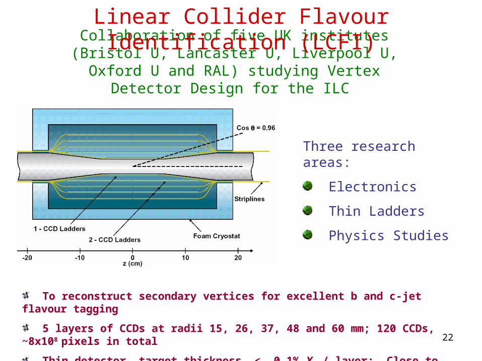
To reconstruct secondary vertices for excellent b and c-jet flavour tagging
5 layers of CCDs at radii 15, 26, 37, 48 and 60 mm; 120 CCDs, ~8x108 pixels in total
Thin detector, target thickness < 0.1% X0 / layer; Close to the interaction point
Collaboration of five UK institutes (Bristol U, Lancaster U, Liverpool U, Oxford U and RAL) studying Vertex Detector Design for the ILC
Linear Collider Flavour Identification (LCFI)
Three research areas:
Electronics
Thin Ladders
Physics Studies
23
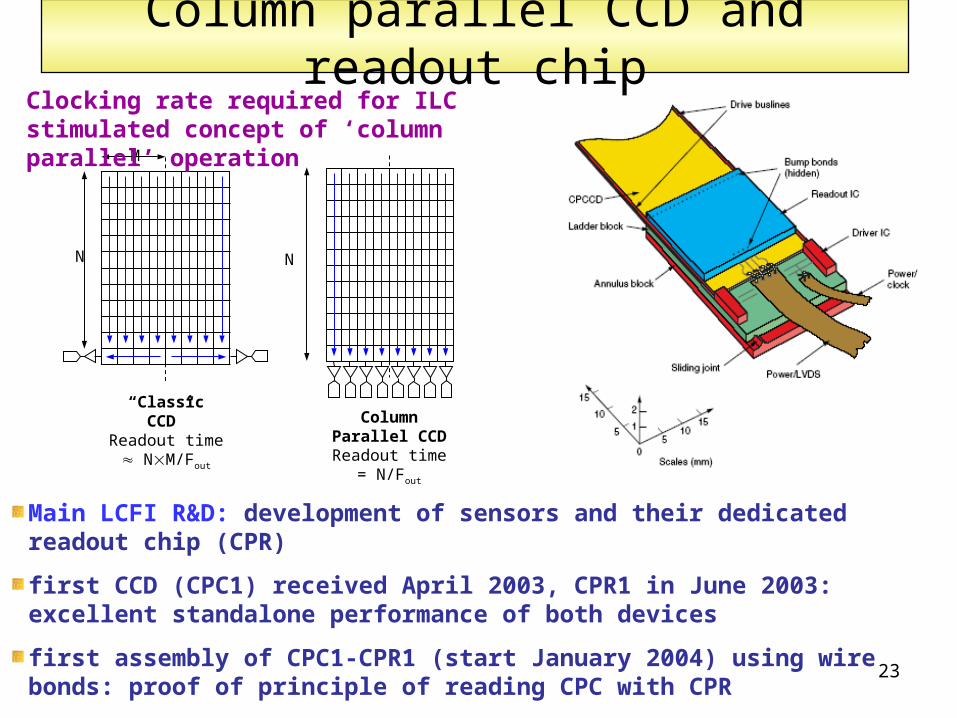
Column parallel CCD and readout chip
“Classic CCD”Readout time
NM/Fout
N
M
N
Column Parallel CCD
Readout time = N/Fout
Clocking rate required for ILC stimulated concept of ‘column parallel’ operation
Main LCFI R&D: development of sensors and their dedicated readout chip (CPR)
first CCD (CPC1) received April 2003, CPR1 in June 2003: excellent standalone performance of both devices
first assembly of CPC1-CPR1 (start January 2004) using wire bonds: proof of principle of reading CPC with CPR
detailed tests of first bump-bonded assembly (ongoing since May 2004)
24
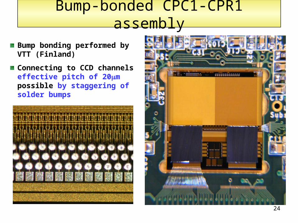
Bump-bonded CPC1-CPR1 assembly
Bump bonding performed by VTT (Finland)
Connecting to CCD channels effective pitch of 20m possible by staggering of solder bumps
25
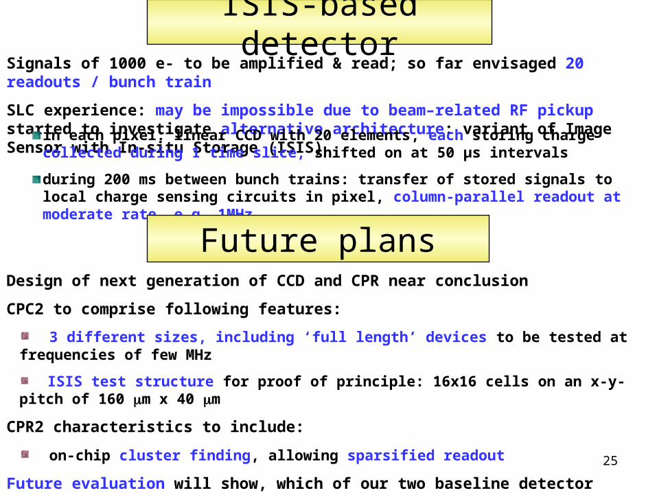
ISIS-based detectorSignals of 1000 e- to be amplified & read; so far envisaged 20 readouts / bunch train
SLC experience: may be impossible due to beam–related RF pickup started to investigate alternative architecture: variant of Image Sensor with In-situ Storage (ISIS)
in each pixel: linear CCD with 20 elements, each storing charge collected during 1 time slice, shifted on at 50 μs intervals
during 200 ms between bunch trains: transfer of stored signals to local charge sensing circuits in pixel, column-parallel readout at moderate rate, e.g. 1MHz
Future plansDesign of next generation of CCD and CPR near conclusion
CPC2 to comprise following features:
3 different sizes, including ‘full length’ devices to be tested at frequencies of few MHz
ISIS test structure for proof of principle: 16x16 cells on an x-y-pitch of 160 m x 40 m
CPR2 characteristics to include:
on-chip cluster finding, allowing sparsified readout
Future evaluation will show, which of our two baseline detector designs – CPCCDs or ISIS – will be better matched to the requirements.
26
3 2
44
/sinp
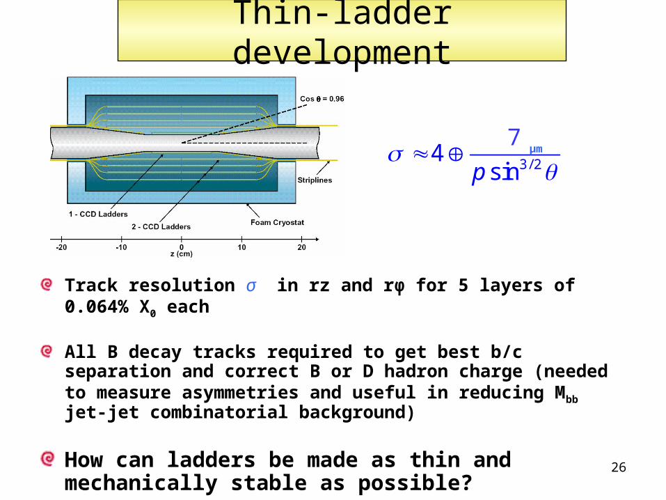
Thin-ladder development
Track resolution σ in rz and rφ for 5 layers of 0.064% X0 each
All B decay tracks required to get best b/c separation and correct B or D hadron charge (needed to measure asymmetries and useful in reducing Mbb jet-jet combinatorial background)
How can ladders be made as thin and mechanically stable as possible?
7μm
27
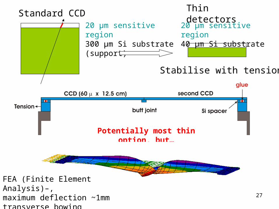
Thin detectorsStandard CCD20 μm sensitive region300 μm Si substrate (support)
Stabilise with tension
20 μm sensitive region40 μm Si substrate
Potentially most thin option, but…
FEA (Finite Element Analysis)–,maximum deflection ~1mmtransverse bowing effects
28 Ripple size: about 160 microns
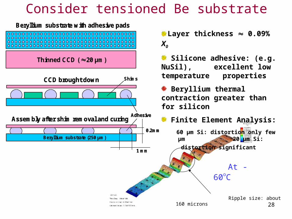
Consider tensioned Be substrate
CCD brought down
Assembly after shim removal and curing
Beryllium substrate (250 μm)
Beryllium substrate with adhesive pads
Thinned CCD ( 20 μm)
Adhesive
Shims
1 mm
0.2mm
CCD brought down
Assembly after shim removal and curing
Beryllium substrate (250 μm)
Beryllium substrate with adhesive pads
Thinned CCD ( 20 μm)
Adhesive
Shims
1 mm
0.2mm
Layer thickness 0.09% X0
Silicone adhesive: (e.g. NuSil), excellent low temperature properties
Beryllium thermal contraction greater than for silicon
Finite Element Analysis:
60 μm Si: distortion only few μm
20 μm Si: distortion significant
At -60oC
29
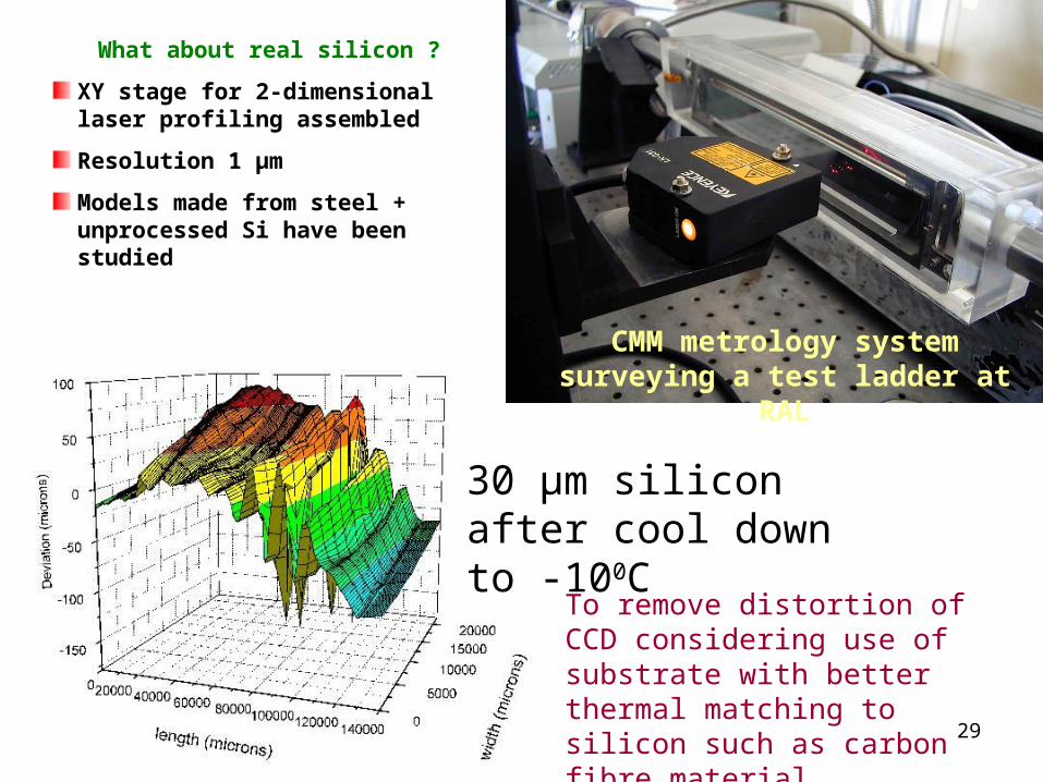
What about real silicon ?
XY stage for 2-dimensional laser profiling assembled
Resolution 1 μm
Models made from steel + unprocessed Si have been studied
CMM metrology system surveying a test ladder at RAL
30 μm silicon after cool down to -100C
To remove distortion of CCD considering use of substrate with better thermal matching to silicon such as carbon fibre material
30
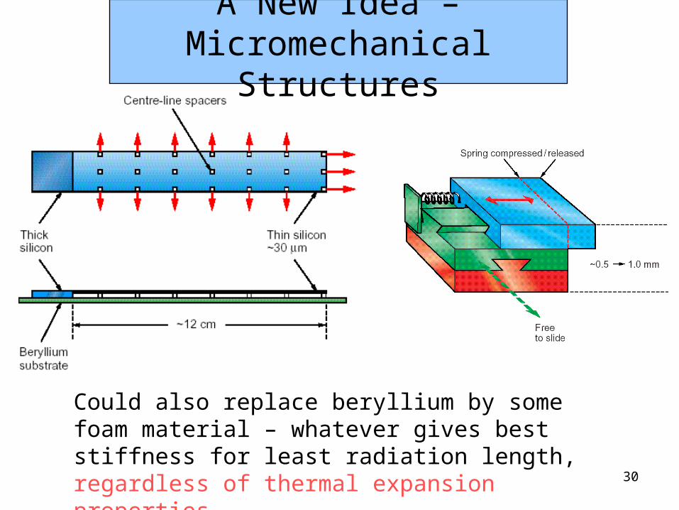
Could also replace beryllium by some foam material – whatever gives best stiffness for least radiation length, regardless of thermal expansion properties
A New Idea – Micromechanical Structures
31
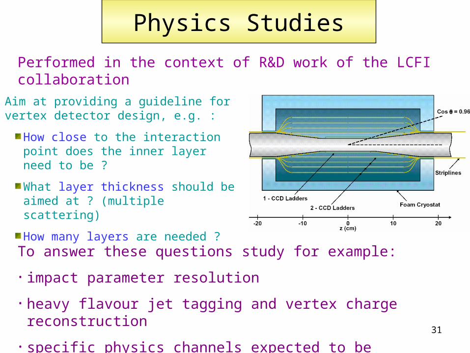
Aim at providing a guideline for vertex detector design, e.g. :
How close to the interaction point does the inner layer need to be ?
What layer thickness should be aimed at ? (multiple scattering)
How many layers are needed ?
Physics Studies
Performed in the context of R&D work of the LCFI collaboration
To answer these questions study for example:
• impact parameter resolution
• heavy flavour jet tagging and vertex charge reconstruction
• specific physics channels expected to be sensitive
32
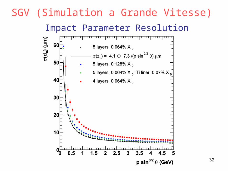
Impact Parameter Resolution
SGV (Simulation a Grande Vitesse)
33
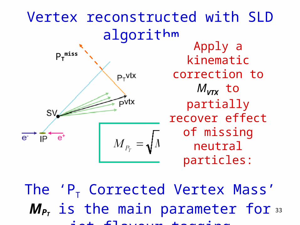
PTmiss
Vertex reconstructed with SLD algorithm
The ‘PT Corrected Vertex Mass’ MPT is the main parameter for jet flavour tagging
Apply a kinematic correction to MVTX to
partially recover effect of missing neutral particles:
34
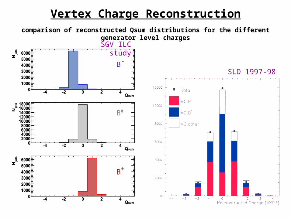
Vertex Charge Reconstructioncomparison of reconstructed Qsum distributions for the different generator level charges
SGV ILC study
SLD 1997-98B-
B0
B+
35
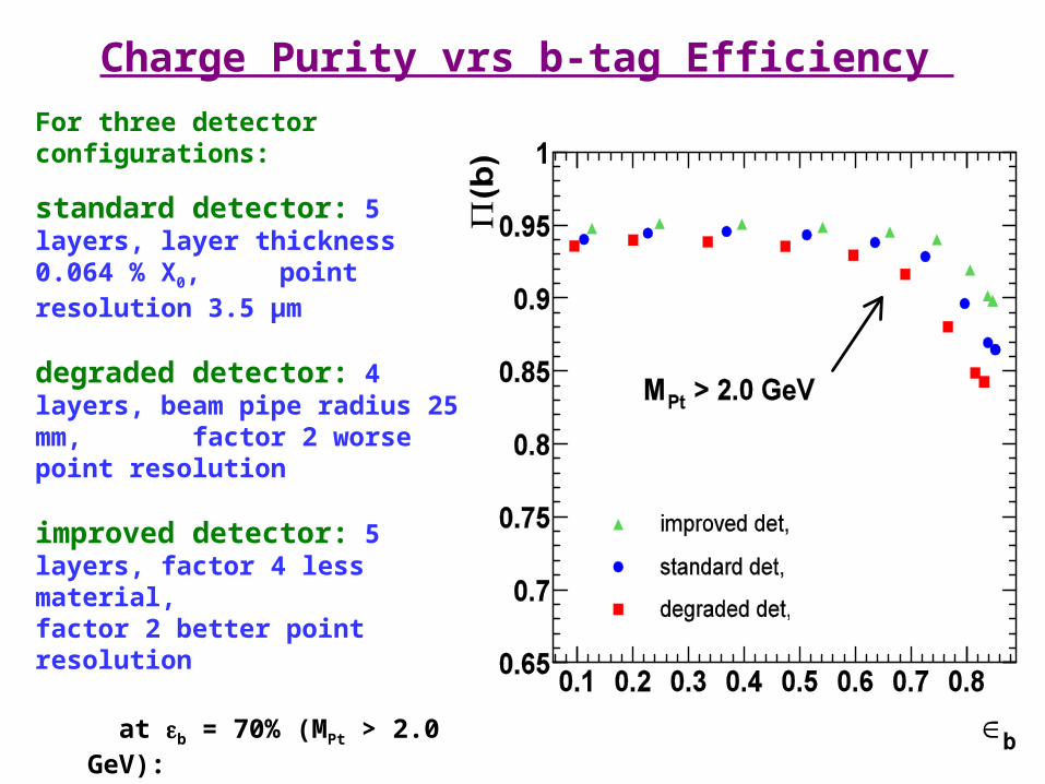
Charge Purity vrs b-tag Efficiency
For three detector configurations:
standard detector: 5 layers, layer thickness 0.064 % X0, point resolution 3.5 μm
degraded detector: 4 layers, beam pipe radius 25 mm, factor 2 worse point resolution
improved detector: 5 layers, factor 4 less material, factor 2 better point resolution
at b = 70% (MPt > 2.0 GeV):
b = 6%, (b) = 2%
Result underlines preference for a small beam pipe radius
36
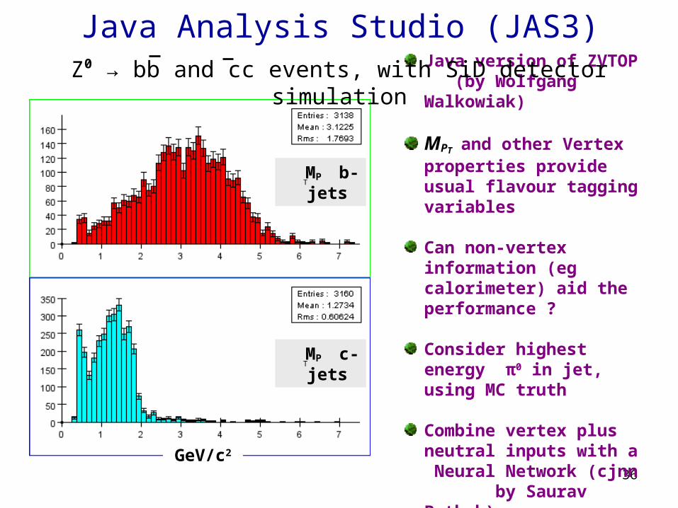
Java Analysis Studio (JAS3)
Java version of ZVTOP (by Wolfgang Walkowiak)
MPT and other Vertex properties provide usual flavour tagging variables
Can non-vertex information (eg calorimeter) aid the performance ?
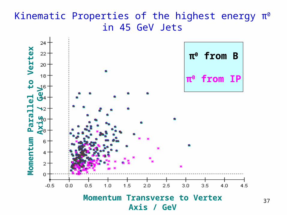
Consider highest energy π0 in jet, using MC truth
Combine vertex plus neutral inputs with a Neural Network (cjnn by Saurav Pathak)
MP b-jets
MP c-jets
GeV/c2
T
T
Z0 → bb and cc events, with SiD detector simulation
37
π0 from B
π0 from IP
Mo
men
tum
Pa
ralle
l to
Ve
rte
x A
xis
/ G
eV
Momentum Transverse to Vertex Axis / GeV
Kinematic Properties of the highest energy π0 in 45 GeV Jets
38
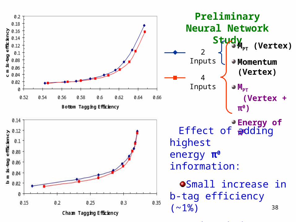
Preliminary Neural Network Study
2 InputsMPT (Vertex)
Momentum (Vertex)
MPT (Vertex + π0)
Energy of π0
4 Inputs
Effect of adding highest energy π0 information:
Small increase in b-tag efficiency (~1%)
Reduce b-jet background to c-tag by a relative 10–25%
39
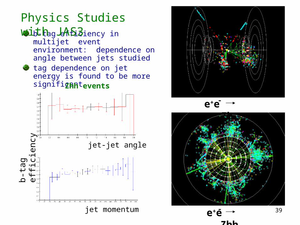
b-tag efficiency in multijet event environment: dependence on angle between jets studiedtag dependence on jet energy is found to be more significant
e+e Zh
e+e Zhh
Physics Studies with JAS3b
-tag
effi
cien
cy
jet-jet angle
jet momentum
Zhh events
40
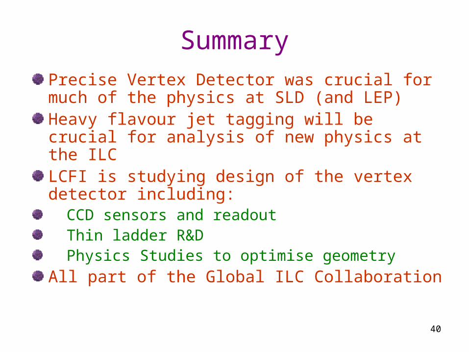
SummaryPrecise Vertex Detector was crucial for much of the physics at SLD (and LEP) Heavy flavour jet tagging will be crucial for analysis of new physics at the ILCLCFI is studying design of the vertex detector including: CCD sensors and readout Thin ladder R&D Physics Studies to optimise geometryAll part of the Global ILC Collaboration