Embed Size (px)
Citation preview
1
Outline of the lecture:
Chandana:
1. Introduction2. Example 3. Definition 4. Vector table and Maskable/nonmaskable interrupts ________________________________________________
Hao:
5. Stack status 6. HPRIO 7. Example
Introduction to Interrupts

Polling and Interrupts
• Polling- Imagine a phone without a bell. You would have to periodically answer the phone to see if anyone is there
• Interrupt – Phone with a bell. You can do something else and stop and answer the phone when it rings
2
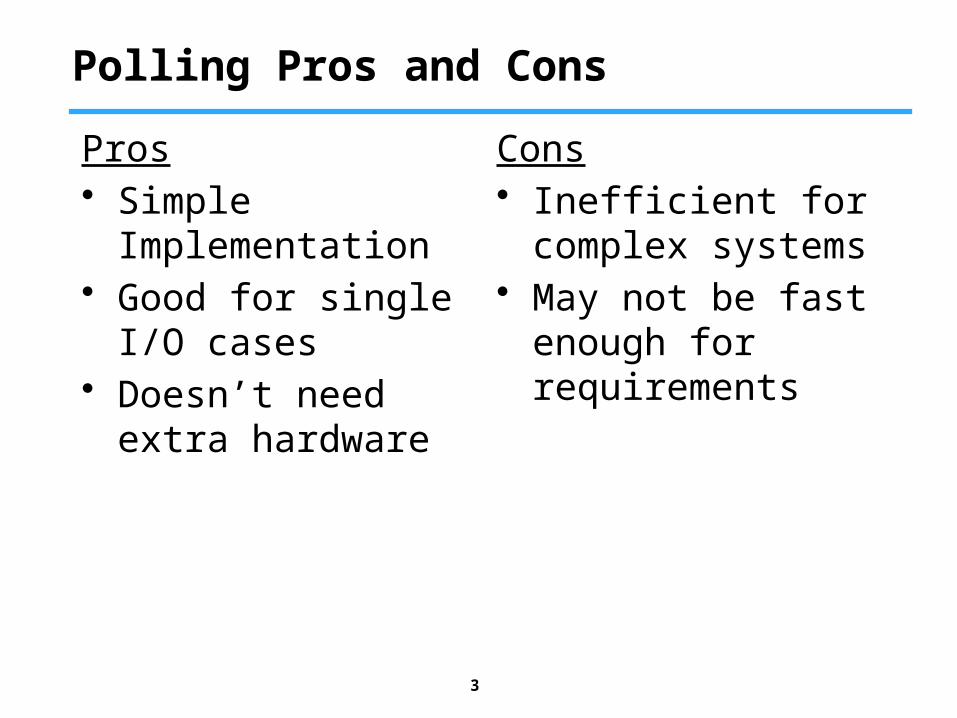
Polling Pros and Cons
Pros• Simple
Implementation• Good for single I/O
cases• Doesn’t need extra
hardware
Cons• Inefficient for
complex systems• May not be fast
enough for requirements
3
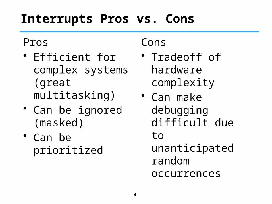
Interrupts Pros vs. Cons
Pros• Efficient for complex
systems (great multitasking)
• Can be ignored (masked)
• Can be prioritized
Cons• Tradeoff of
hardware complexity• Can make
debugging difficult due to unanticipated random occurrences
4
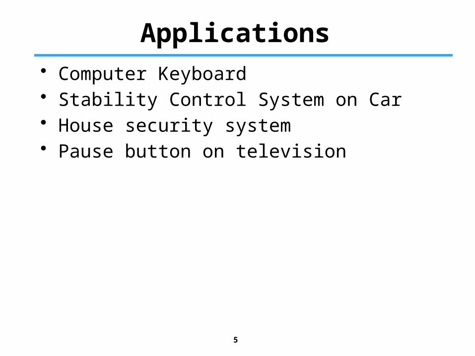
Applications
5
• Computer Keyboard• Stability Control System on Car• House security system• Pause button on television
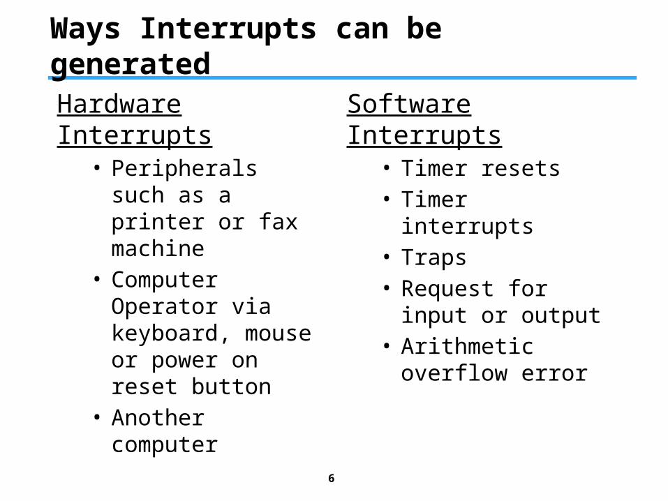
Ways Interrupts can be generated
Hardware Interrupts• Peripherals such as
a printer or fax machine
• Computer Operator via keyboard, mouse or power on reset button
• Another computer
Software Interrupts• Timer resets• Timer interrupts• Traps• Request for input or
output• Arithmetic overflow
error
6
Some Definitions
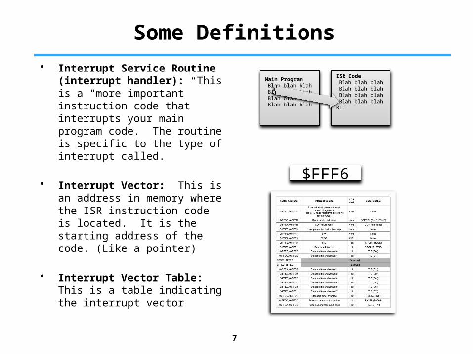
• Interrupt Service Routine (interrupt handler): This is a “more important” instruction code that interrupts your main program code. The routine is specific to the type of interrupt called.
• Interrupt Vector: This is an address in memory where the ISR instruction code is located. It is the starting address of the code. (Like a pointer)
• Interrupt Vector Table: This is a table indicating the interrupt vector
7
ISR CodeBlah blah blahBlah blah blahBlah blah blahBlah blah blah
RTI
Main ProgramBlah blah blahBlah blah blahBlah blah blahBlah blah blah
$FFF6
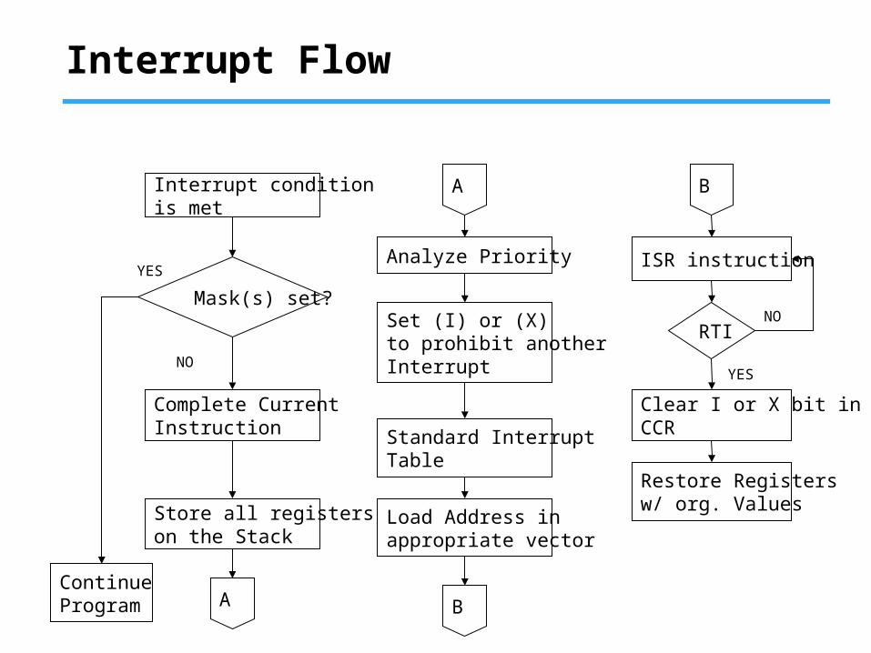
Interrupt Flow
Interrupt conditionis met
Restore Registersw/ org. Values
Standard InterruptTable
Analyze Priority
Store all registerson the Stack
Mask(s) set?
ContinueProgram
Complete CurrentInstruction
A
Set (I) or (X) to prohibit another Interrupt
Load Address inappropriate vector
YES
NO
ISR instruction
Clear I or X bit inCCR
RTI
YES
NO
B
B
A

Non-Maskable Interrupts
9
• 6 Non-Maskable Interrupts
• Higher Priority than maskable interrupts
• Can interrupt Maskable Interrupt ISRs
• X=1 ONLY disables XIRQ interrupt (and all other interrupts are still enabled when X=1)
1. POR of RESET pin
2. Clock monitor reset
3. COP watchdog reset
4. Unimplemented instruction trap
5. Software interrupt (SWI)
6. XIRQ interrupt

XIRQ & IRQ
10
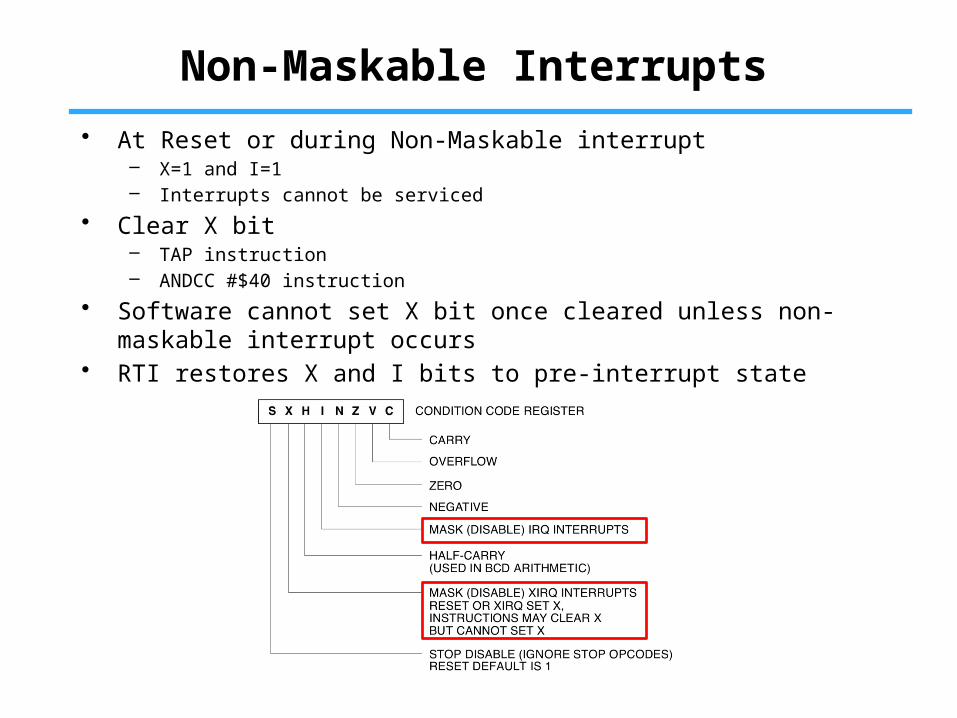
Non-Maskable Interrupts
• At Reset or during Non-Maskable interrupt– X=1 and I=1– Interrupts cannot be serviced
• Clear X bit– TAP instruction– ANDCC #$40 instruction
• Software cannot set X bit once cleared unless non-maskable interrupt occurs
• RTI restores X and I bits to pre-interrupt state
Non-Maskable Interrupts
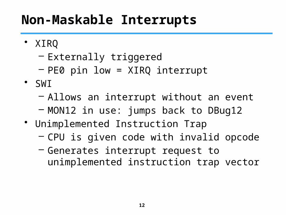
• XIRQ– Externally triggered– PE0 pin low = XIRQ interrupt
• SWI– Allows an interrupt without an event– MON12 in use: jumps back to DBug12
• Unimplemented Instruction Trap– CPU is given code with invalid opcode– Generates interrupt request to unimplemented
instruction trap vector
12
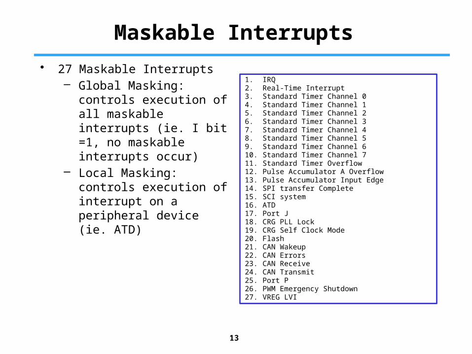
Maskable Interrupts
• 27 Maskable Interrupts– Global Masking: controls
execution of all maskable interrupts (ie. I bit =1, no maskable interrupts occur)
– Local Masking: controls execution of interrupt on a peripheral device (ie. ATD)
13
1. IRQ2. Real-Time Interrupt3. Standard Timer Channel 04. Standard Timer Channel 15. Standard Timer Channel 26. Standard Timer Channel 37. Standard Timer Channel 48. Standard Timer Channel 59. Standard Timer Channel 610. Standard Timer Channel 711. Standard Timer Overflow12. Pulse Accumulator A Overflow13. Pulse Accumulator Input Edge14. SPI transfer Complete15. SCI system16. ATD17. Port J18. CRG PLL Lock19. CRG Self Clock Mode20. Flash21. CAN Wakeup22. CAN Errors23. CAN Receive24. CAN Transmit25. Port P26. PWM Emergency Shutdown27. VREG LVI
Maskable Interrupts
14
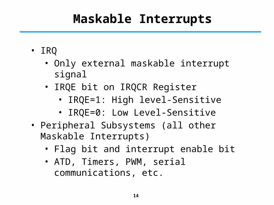
• IRQ• Only external maskable interrupt signal• IRQE bit on IRQCR Register
• IRQE=1: High level-Sensitive• IRQE=0: Low Level-Sensitive
• Peripheral Subsystems (all other Maskable Interrupts)• Flag bit and interrupt enable bit• ATD, Timers, PWM, serial communications,
etc.
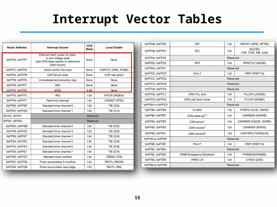
Interrupt Vector Tables
15
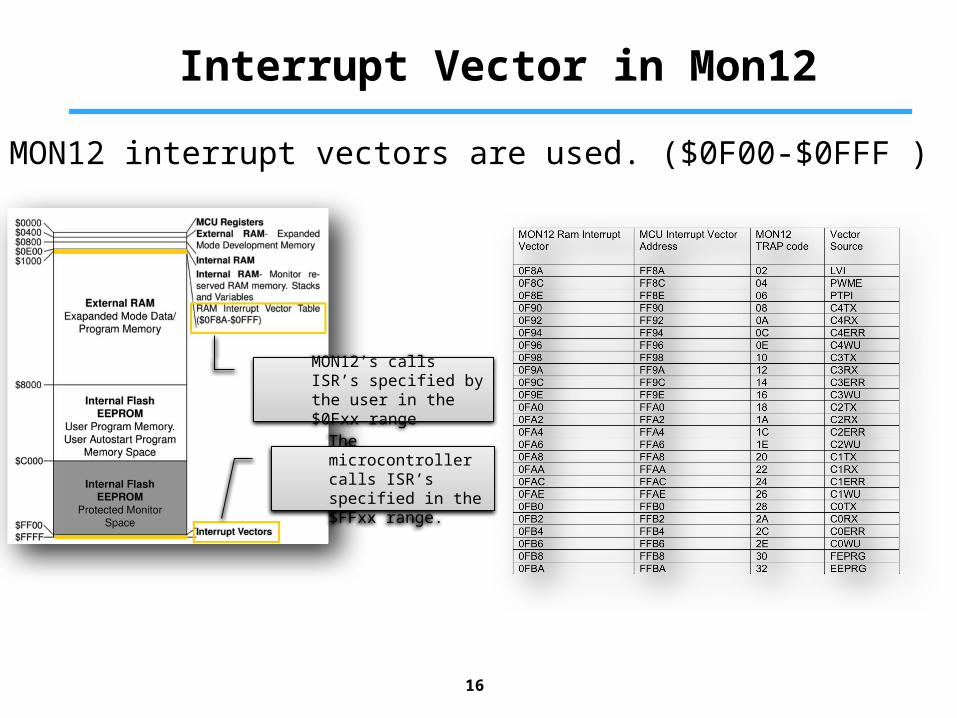
Interrupt Vector in Mon12
16
MON12’s calls ISR’s specified by the user in the $0Fxx range
The microcontroller calls ISR’s specified in the $FFxx range.
MON12 interrupt vectors are used. ($0F00-$0FFF )

Interrupts: Stack
CCR
ACC B
ACC A
X HI
X LO
Y HI
Y LO
RTN HI
RTN LOFirst Pushed In
Last Pulled Off
Last Pushed In
First Pulled Off
Higher Address
Lower Address
Stack Pointer before Interrupt
Stack Pointer after Interrupt
• RTN – address of next instruction in Main Program, upon return from interrupt.
• X LO and Y LO are the low bytes of X and Y registers.
• X HI and Y HI are the high bytes of X and Y registers.
• ACC A and ACC B are the accumulators.• CCR is the Code Condition Register
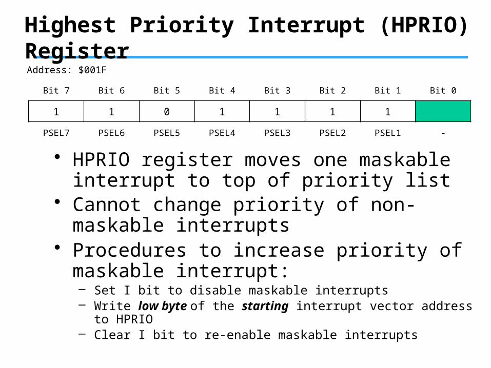
Highest Priority Interrupt (HPRIO) Register
• HPRIO register moves one maskable interrupt to top of priority list
Address: $001F
Bit 7 Bit 6 Bit 5 Bit 4 Bit 3 Bit 2 Bit 1 Bit 0
1 1 0 1 1 1 1
PSEL7 PSEL6 PSEL5 PSEL4 PSEL3 PSEL2 PSEL1 -
• Cannot change priority of non-maskable interrupts
• Procedures to increase priority of maskable interrupt:– Set I bit to disable maskable interrupts– Write low byte of the starting interrupt vector address to HPRIO– Clear I bit to re-enable maskable interrupts
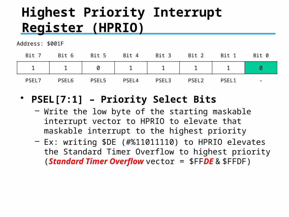
Highest Priority Interrupt Register (HPRIO)
Address: $001F
Bit 7 Bit 6 Bit 5 Bit 4 Bit 3 Bit 2 Bit 1 Bit 0
1 1 0 1 1 1 1 0
PSEL7 PSEL6 PSEL5 PSEL4 PSEL3 PSEL2 PSEL1 -
• PSEL[7:1] – Priority Select Bits– Write the low byte of the starting maskable interrupt vector to
HPRIO to elevate that maskable interrupt to the highest priority– Ex: writing $DE (#%11011110) to HPRIO elevates the Standard
Timer Overflow to highest priority (Standard Timer Overflow vector = $FFDE & $FFDF)
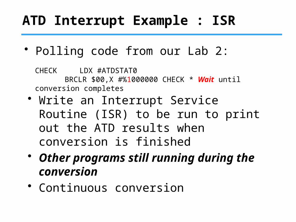
ATD Interrupt Example : ISR
• Write an Interrupt Service Routine (ISR) to be run to print out the ATD results when conversion is finished
• Other programs still running during the conversion
• Continuous conversion
CHECK LDX #ATDSTAT0 BRCLR $00,X #%1000000 CHECK * Wait until conversion completes
• Polling code from our Lab 2:
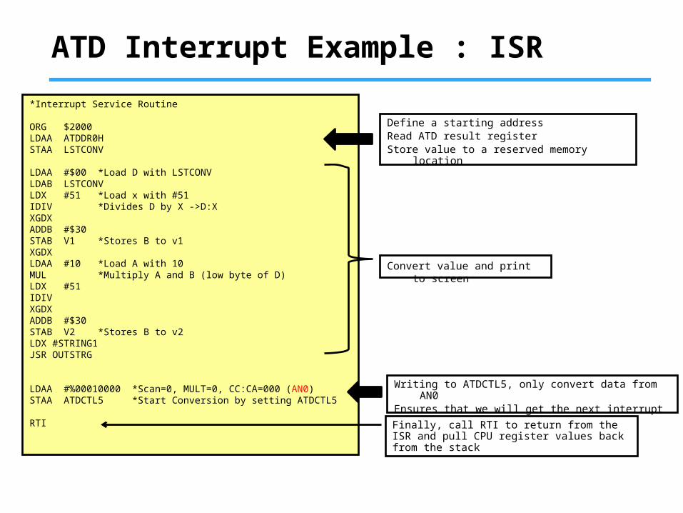
ATD Interrupt Example : ISR
*Interrupt Service Routine
ORG $2000LDAA ATDDR0HSTAA LSTCONV
LDAA #$00 *Load D with LSTCONVLDAB LSTCONVLDX #51 *Load x with #51IDIV *Divides D by X ->D:XXGDXADDB #$30STAB V1 *Stores B to v1 XGDXLDAA #10 *Load A with 10MUL *Multiply A and B (low byte of D)LDX #51IDIVXGDXADDB #$30STAB V2 *Stores B to v2LDX #STRING1JSR OUTSTRG
LDAA #%00010000 *Scan=0, MULT=0, CC:CA=000 (AN0)STAA ATDCTL5 *Start Conversion by setting ATDCTL5
RTI
Define a starting addressRead ATD result registerStore value to a reserved memory location
Convert value and print to screen
Writing to ATDCTL5, only convert data from AN0Ensures that we will get the next interrupt (SCF is cleared)
Finally, call RTI to return from the ISR and pull CPU register values back from the stack
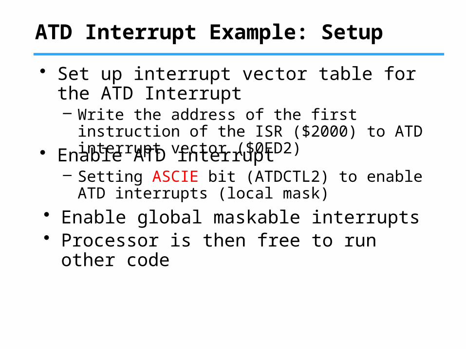
ATD Interrupt Example: Setup
• Set up interrupt vector table for the ATD Interrupt– Write the address of the first instruction of the ISR
($2000) to ATD interrupt vector ($0FD2)
• Enable ATD interrupt– Setting ASCIE bit (ATDCTL2) to enable ATD
interrupts (local mask)
• Enable global maskable interrupts• Processor is then free to run other code
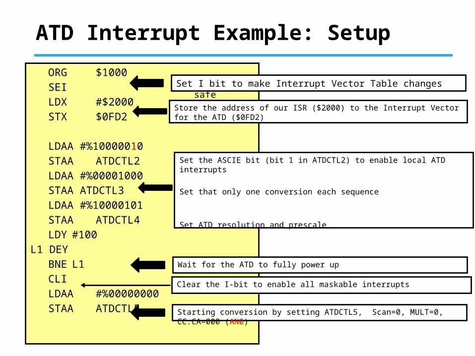
ATD Interrupt Example: Setup
ORG $1000SEILDX #$2000STX $0FD2
LDAA #%10000010STAA ATDCTL2LDAA #%00001000STAA ATDCTL3LDAA #%10000101STAA ATDCTL4LDY #100
L1 DEYBNE L1CLILDAA #%00000000STAA ATDCTL5
Store the address of our ISR ($2000) to the Interrupt Vector for the ATD ($0FD2)
Set the ASCIE bit (bit 1 in ATDCTL2) to enable local ATD interrupts
Set that only one conversion each sequence
Set ATD resolution and prescale
Wait for the ATD to fully power up
Clear the I-bit to enable all maskable interrupts
Starting conversion by setting ATDCTL5, Scan=0, MULT=0, CC:CA=000 (AN0)
Set I bit to make Interrupt Vector Table changes safe
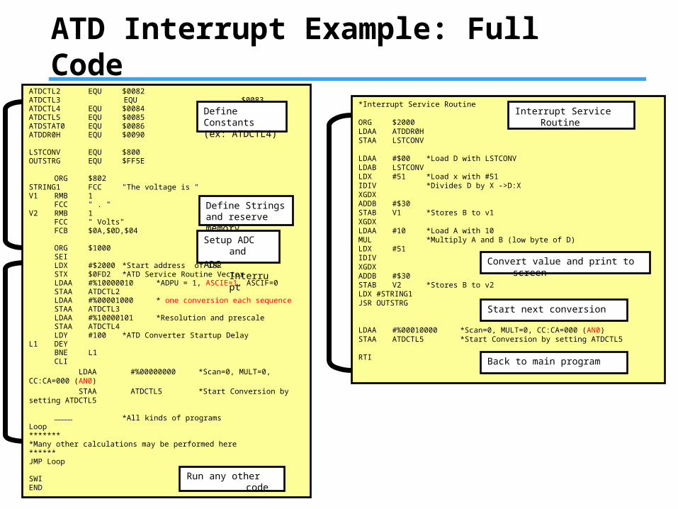
ATD Interrupt Example: Full CodeATDCTL2 EQU $0082ATDCTL3 EQU $0083ATDCTL4 EQU $0084ATDCTL5 EQU $0085ATDSTAT0 EQU $0086ATDDR0H EQU $0090
LSTCONV EQU $800OUTSTRG EQU $FF5E
ORG $802STRING1 FCC "The voltage is "V1 RMB 1
FCC " . "V2 RMB 1
FCC " Volts"FCB $0A,$0D,$04
ORG $1000SEILDX #$2000 *Start address of ISRSTX $0FD2 *ATD Service Routine VectorLDAA #%10000010 *ADPU = 1, ASCIE=1, ASCIF=0STAA ATDCTL2LDAA #%00001000 * one conversion each sequenceSTAA ATDCTL3LDAA #%10000101 *Resolution and prescaleSTAA ATDCTL4LDY #100 *ATD Converter Startup Delay
L1 DEYBNE L1CLI
LDAA #%00000000 *Scan=0, MULT=0, CC:CA=000 (AN0) STAA ATDCTL5 *Start Conversion by setting ATDCTL5
………… *All kinds of programsLoop********Many other calculations may be performed here******JMP Loop
SWIEND
*Interrupt Service Routine
ORG $2000LDAA ATDDR0HSTAA LSTCONV
LDAA #$00 *Load D with LSTCONVLDAB LSTCONVLDX #51 *Load x with #51IDIV *Divides D by X ->D:XXGDXADDB #$30STAB V1 *Stores B to v1 XGDXLDAA #10 *Load A with 10MUL *Multiply A and B (low byte of D)LDX #51IDIVXGDXADDB #$30STAB V2 *Stores B to v2LDX #STRING1JSR OUTSTRG
LDAA #%00010000 *Scan=0, MULT=0, CC:CA=000 (AN0)STAA ATDCTL5 *Start Conversion by setting ATDCTL5
RTI
Define Constants(ex: ATDCTL4)
Define Strings and reserve memory
Setup ADC and
ADC Interrupt
Run any other code
Convert value and print to screen
Interrupt Service Routine
Start next conversion
Back to main program


![[Guest Editor, Chandana Jayawardena.] Tourism and (BookFi.org)](https://img.pdfslide.us/doc/110x75/55cf8e8b550346703b933cde/guest-editor-chandana-jayawardena-tourism-and-bookfiorg.jpg)