Embed Size (px)
Citation preview
lYSi56'LWl No. 01
r Thank you for buying the JUKI MOJ/MOK-2500N
BEFORE OPERATION
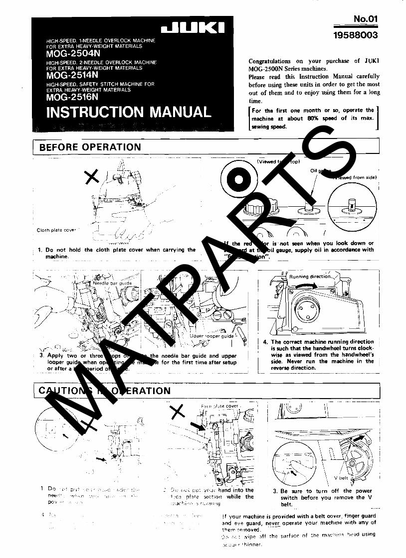
1. Do not hold the cloth plate cover when carrying the machine.
2. Resupply oil if the red color in the oil gauge is not seen when the oil gauge i s observed from the top or the side.
3. Apply a few drops of oil to the needle bar guide and upper looper guide before operating your new rnach~ne or starting your machine for the first time ~n a ioog time. Also, lubricate the oil holi: sf link (A ) and ttre top feed presser bar. (Refer ?o "2, LUBRiCATiUN".i
4. Never allow the sewing machine to sun in the reverse directioi!. The hdndwhrei shrjr;ld rcirr. clockwise as
1 series sewing machine. The MOJIMOK-2500N series
I models have basically the &me mechanism as those of MOG-2500N series models except that the top feed mechanism has been incorporated in MOJ/MOK-2500N series models. For this reason, I t h l Instruction Manual mainly deals with the too
I feed mechanism only. he customers are re- quested to refer to separate instruction Manuals of MOG-2500N series models for the common instruc- tions omitted from this manual.
MOJ 1 (Example) For MOK - 25 16N
Top feed mechanism
I CAUTIONS IN OPERATION I 1. Do not put your hand under or near the needle when
turning the power switch ON or while the machine i s operating.
2. Do not put your fingers into the face plate cover while the machine i s operating.
3. Be sure to turn the power switch OFF when removing the V belt.
4 Dor~ng operation, be careful not to allow your or any other person's head or hands to come, or place anything close to the pulley, V belt or motor. Any of these actions may develop dangerous conditions. " i f vour machine i s provided with a belt cover, finger guard CJT any other protectors, never operate your machine with any of these removed.
F. Do not wlpe off the surface of the machine head using racouer thinner.
.- - - - --
1 - .- -- -- .-. . .~ --. ...-.-.----.--.-".A .... .-
1 .,;:).:~:..;::* - : , . ~ MOK-3500N series . ~- ~~ ~. -
.;j,-:.:- l%., . ~ . . ~. ~~-~ ~- ~
7 , . . h ;, : : i:~~:!?. ,,!.t:':; ,!l i ,kL, . ,.- . : - ,-' ,.. . r: .;j , .> t . ..: i , 6 :,i.:,.;. f,(;l;<j . :- j,i.
I \ : i / : i +, , !. f i<:1: : :9!!.3; , ( ; ,>kc , of
M a x . 6000 s.p.m. . . - . ., . . :::. if:. \ '(11 i f ; , :cr>
~ ~ ~- ~ ~ ~ ~
. . . I : i : >r .i,,:.~:-,,:i 1 : : < .i:
. . . . - i . i i : . ' : , . /
, :. *..; ~ . ~.
, :, , ~~-~ -~
i 1 !;[ {,<t:.,: !. :>-,.: , ' \ , C ~~ < - - - -
, - ' Y;:~I , < , 2 i x?:c,kL, L,+ !<j? : ; ,, ,!, ,! 4 -, 8 - , ; : ~ : , ,
- .-- ~ . ~
5 - 6.5 mm - ---- - - -- -
j 1 ~ l r ~ . ~ ~ ? ~ ~ , l i : : a l \:rok\> <)t ::;~j ic, J ..its 3 ; I ! ; , ; - ~-~ ~ - -
Max. 6 mm
1 Lift o i ;?ri.\cr f ~ o ! Y i ; r r , 8 mm
I * i Zleans the ratio , i t !hi: rndi!l r e d 3oi.r i!:~:giru.lii?:~l .trok.r t , ? the !op feed dog longitudinal stroke. This ratio is factory- adjusted to 1 : l . I -. 1 ::.8 for t he blOJ-:( 136, a ~ i d i :0.7 - ! : 1.8 for the MOJ-2516N.
( " 2 ) The top feed dog has 3 long end for betre: <titchine perforn:ance. When the maximum longitudinal stroke of 8.5 m m of the top feed dug is nece.;sar)~. out the end ot t he top feed dog b l 3 mm by a maximum.
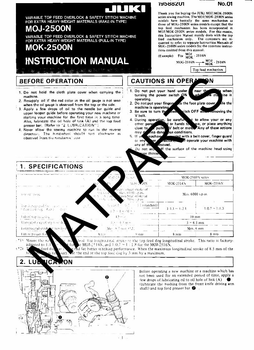
12. LUBRICATION ~p~ -~ - - -
Before operating a new machine or a machine which has no t been used for an extended period of t ime, apply a few drops of lubricating oil t o oil hole of link ( A ) 0 (lubricate the bushing from the front knife driving arm shaft) and top feed presser bar @ .
MATPARTS
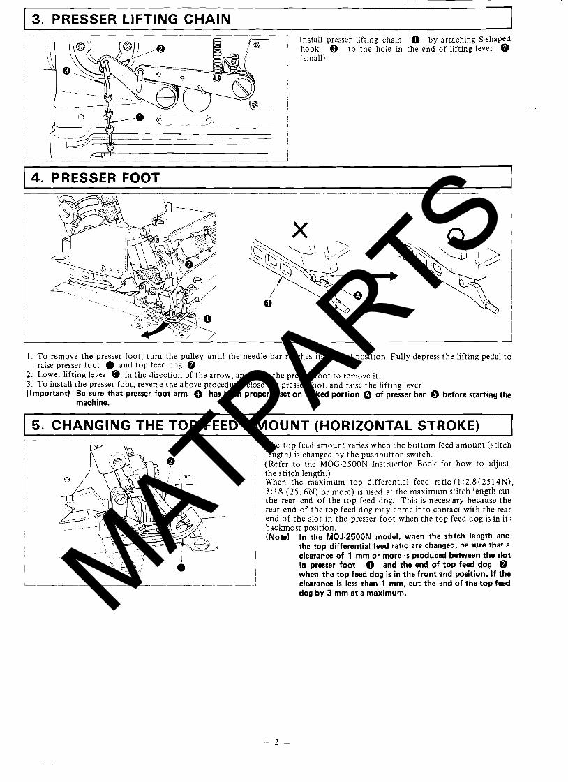
. 3. PRESSER LIFTING CHAIN
Install presser lifting chain by attaching S-shaped hook @ to the hole in the end of lifting lever @ (small).
4. PRESSER FOOT
1. To remove the presser foot, turn the pulley anti1 the needle bar reaches its highest position. Fully depress the lifting pedal t o raise presser foot 0 and top feed dog @ .
2. Lower lifting lever @ in the direction of the arrow, and open the presser foot to remove it . 3. To install the presser foot, reverse the above procedure, close the presser foot, and raise the lifting lever. (Important) Be sure that presser foot arm @ has been properly set on forked portion 0 of presser bar Q before starting the
machine.
5. CHANGING THE TOP FEED AMOUNT (HORIZONTAL STROKE) The t op feed amount varies when the bottom feed amount (stitch length) is changed by the pushbutton switch. (Refer t o the MOG-2500N Instruction Book for how to adjust the stitch length.) When the maximum top differential feed rat io( l :2.8(2514N), 1: 18 (2516N) or more) is used at the maximum stitch length cut the rear end of the t op feed dog. This is necessary because the rear end of the top feed dog may come into contact with the rear end of the slot in the presser foot when the top feed dog is in its backmost position. (Note) In the MOJ-2500N model, when the stitch length and
the top differential feed ratio are changed, be sure that a clearance of 1 mm or more i s produced between the slot in presser foot and the end of top feed dog @ when the top feed dog i s in the front end position. I f the clearance is less than 1 mm, cut the end of the top feed dog by 3 mm at a maximum. MATPARTS
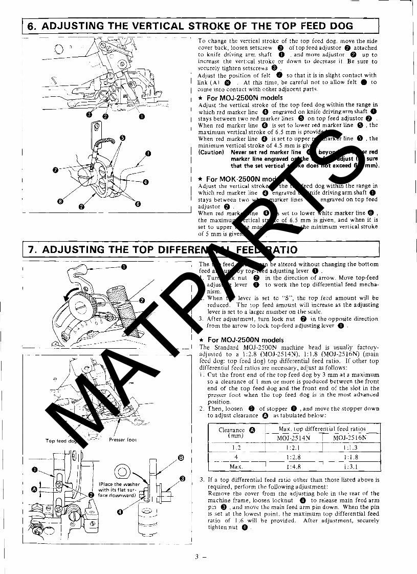
6. ADJUSTING THE VERTICAL STROKE OF THE TOP FEED DOG I -- - - -- - -
7 To change the vertical stroke of the top feed dog, move the side cover back, loosen setscrew @ of top feed adjustor @ attached t o knife driving arm shaft 0 . and move adjustor @ up t o increase the vertical stroke or down to decrease it. Be sure t o securely tighten setscrews @ . Adjust the position of felt @ so that it is in slight contact with link (A) @ . At this time, be careful not to allow felt 0 t o come into contact with other adjacent parts.
* For MOJ-2500N models Adjust the vertical stroke of the top feed dog within the range in which red marker line @ engraved on knife driving arm shaft 0 stays between two red marker lines @ on top feed adjustor @ . When red marker line @ is set to lower red marker line @ , the maximum vertical stroke of 6.5 mm is provided. When red marker Line @ is set t o upper red marker line @ , the minimum vertical stroke of 4.5 mm is given. (Caution) Never set red marker line 0 beyond the lower red
marker line engraved on the top feed adjust (Be sure that the set vertical stroke does not exceed 6.5 mm).
* For MOK-25001U models Adjust the vertical stroke of the top feed dog within the range in which red marker line 0 engraved on knife drivingarm shaft 0 stays between two white marker lines @ engraved on top feed adjustor @ . When red marker line 0 is set to lower white marker line @ , the maximum vertical stroke of 6.5 mm is given, and when it is set to upper white marker line @ , the minimum vertical stroke of 5 mm is given.
1 7. ADJUSTING THE TOP DIFFERENTIAL FEED RATIO I
1 / e / Top feed dog Presser foot
The top feed amount can be altered without changing the bottom feed amount, by top-feed adjusting lever . 1 . Turn lock nut @ in the direction of arrow. Move top-feed
adjusting lever 0 t o work the top differential feed mecha- nism.
2. When the lever is set to "S", the top feed amount will be reduced. The top feed amount will increase as the adjusting lever is set to a larger number on the scale.
3. After adjustment, turn lock nut @ in the opposite direction from the arrow to lock top-feed adjusting lever 0 .
* For MOJ-2500N models The Standard MOJ-2500N machine head is usuallv factorv- adjusted t o a 1 :2.8 (MOJ-25 14N), 1: 1.8 ( M O J - 2 5 1 6 ~ ) (main feed dog: top feed dog) top differential feed ratio. If other t op differential feed ratios are necessary, adjust as follows: 1 . Cut the front end of the top feed dog by 3 mm a t a maximum
so a clearance of 1 mm or more is produced between the front end of the top feed dog and the front end of the slot in the presser foot when the top feed dog is in the most advanced position.
2. Then, loosen @ of stopper 0 , and move the stopper down to adjust clearance 0 as tabulated below:
Clearance 0 Max. top differential feed ratios
MOJ-2514N MOJ-25 16N
1 :2.1 1:1.3
1 :2.8 1 : 1.8
Max. 1 :4.8
3. If a top differential feed ratio other than those listed above is required, perform the following adjustment: Remove the cover from the adjusting hole in the rear of the machine frame, loosen locknut @ t o release main feed arm pin Q , and move the main feed arm pin down. When the pin is set at the lowest point, the maximum top differential feed ratio of 1 :6 will be provided. After adjustment, securely tighten nut 0 .
MATPARTS
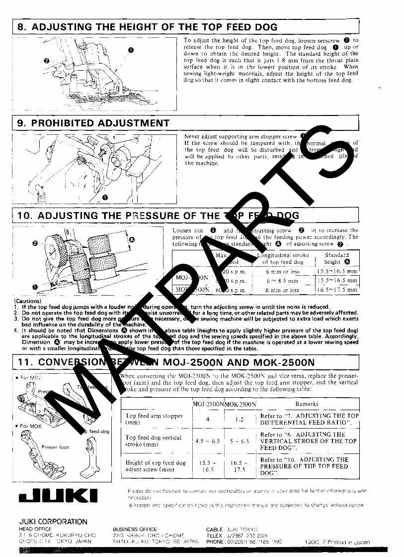
8. ADJUSTING THE HEIGHT OF THE TOP FEED DOG T o adjust the height of the t o p feed dog, loosen setscrew @ t o release the top feed dog. Then, move t o p feed dog 0 up o r down t o obtain the desired height. The standard height of the top feed dog is such that it juts 1.8 m m from the throat plate surface when it is in the lowest position of its stroke. When sewing light-weight materials, adjust the height of the top feed dog so tha t it comes in slight contact with the bo t tom feed dog.
9. PROHIBITED ADJUSTMENT Never adjust supporting arm stopper screw 0 . If the screw should be tampered with, the normal motion of the t o p feed dog will be disturbed and extremely hlgh load will be applied t o other parts, resulting in shortened life of
1 1
1 10, ADJUSTING THE PSESSURE OF THE TOP FEED DOG I . ~ --. ~ ... ~
.~
-7 Loosen nut 0 and turn adjusting screiv @ In to Increase the / pressure of rhe top feed dog and the feeding power accordingly. The
following table shows standard height 0 of adjusting screw @ .
'--- .~
(Cautions) 1. If the top feed dog jumps with a louder noise during operation, turn the adjusting screw in until the noise i s reduced. 2. Do not operate the top feed dog with i t s loud noise uncorrected for a long time,or other related parts may be adversely affected. 3. Do not give the top feed dog more pressure than necessary, or the sewing machine will be subjected to extra load which exerts
bad influence on the durability of the machine. 4. It should be noted that Dimensions 0 shown in the above table (heights to apply slightly higher pressure of the top feed dog)
are applicable to the longitudinal strokes of the top feed dog and the sewing speeds specified in the above table. Accordingly, Dimension 0 may be increased to apply lower pressure of the top feed dog if the machine i s operated a t a lower sewing speed or with a smaller longitudinal stroke of the top feed dog than those specified in the table.
1 I 1. CONVERSION BETWEEN MOJ-2500N AND MOK-2500N For MO?
Top feed dog
When converting the MOJ-?SOON t o the MOK-?SOON and vice versa, replace the presser- foot (asm) and the top feed dog. then adjust the top feed arm stopper, and the vertical stroke arid pressure of the top feed dog according to the following table:
I I MOJ-?SOON/UOK-?~OON/ Remarks I Top feed arm stopper ~ Refer t o "7. ADJUSTING THE TOP
DIFFERENTIAL FEED RATIO".
1 Refer t o "6. ADJUSTING T H E feed 1 4.5 - 6.5 1 5 - 6.5 stroke (mm) I
VERTICAL STROKE O F THE TOP , FEED DOG".
Height of top feed dog 15.5 - 16.5 - Refer t o "10. ADJUSTING THE
adjust screw (mm) 1 16,5 1 PRESSURE O F THE TOY FEED
I DOG".
Please do not hes!tale l o conracr obr d l s t r ~ b i l t o : ~ or agents n vour area fo r further ~n fo r rna t~ons whr necessary
%Appear arld s ~ e c i f c a t ~ o r > l s ted in :hs instruc!ion rnariual are subjected to change wthout no t~ce
JUKl CORPORA1-ION HEAD OFFICE BUSINESS OFFICE CABLE JUKl TOKYO 2-1 8-CHOME KOKURYO CHO 23 3 KABUKI CHO 1 CHOME TELEX 322967 232 2301 ChOFU CITY TOKYO JAPAN SHINJUKU K U TOKYO 160 JAPAN PHONE 03(205)1188 1189 1190 1990 7 Printed In JaDafl
MATPARTS
Congratulations on your purchase of JUKI MOG-2500N Series machines. Please read t h i s Instruction Manual carefully before using these units i n order to get the most out of them and to enjoy using them for a long time.
For the first one month or so, operate the machine at about 80% speed of i t s max. sewing speed. 1
I BEFORE OPERATION
.~.-- 7 , i~ - . . -- , ,,'.. .'
cloth plate cever . -i ,,,;7 . .-
, ! , ,,'T-
b-.ir ,.ti~i..i
- -- -- -
(Vtewed from top)
(Viewed from s~de)
- - .rw~Y-IWT T 2. I f the red color is not seen when you look down or i
1. Do not hold the cloth plate cover when carrying the sideward at the oil gauge, supply oil in accordance with 1 machine. - --
"6. Lubrication". - --
3. Apply two or three drops of oil to the needle bar guide and upper ~ looper guide when operating the machine for the first time after setup or after a long period of disuse. I - - - ---
4. The correct machine running direction is such that the handwheel turns clock- wise as viewed from the handwheel's side. Never run the machine in the reverse direction.
I CAUTIONS IN OPERATION Fdce olate cover ,
. :-, - .I:, i : ~ i pui it.:i~ hand into the 3. Be sure to turn off the power j .-..., SF, i p!?te c x ~ ? ; ~ ~ ~ i while the switch before you remove the V ~::aq!-.;:.::. , s r;,!;!?;.\q
. . belt.
- ~ - ~-
., * . :, 3 . . .;::- 1 f your machine i s provided with a belt wver, finger guard and e y e guard, never operate your mach~ne with any of :hew removed. . lo 7..~r riff :he of ?he machi:?? %ad using
MATPARTS
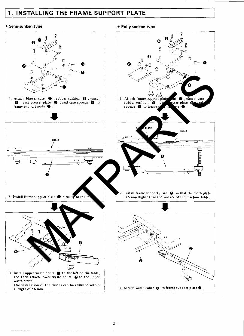
1. INSTALLING THE FRAME SUPPORT PLATE 1 * Semi-sunken type + Fully-sunken type
I I Attach blower case @ , rubber cushion @ , spacer ' Q , case presser plate @ , and case sponge @ t o frame support plate 0 .
Table
1 2. Install frame support plate 0 directly t o the table.
3. Install upper waste chute @ to the left o n the table, and then attach lower waste chute @ to the upper waste chute. The installation of the chutes can be adjusted within a length of 56 mrn.
- - -- - - - - - - - -
1. Attach frame supPo; ;late joint Q , blower case , rubber cushion 0 , case presser plate Q , and case sponge @ to frame support plate 0 .
Cloth plate \. Table I
2. Install frame support plate so that the cloth plate is 5 mm higher than the surface of the machine table.
/ 3. Attach waste chute @ t o frame support plate 0 . - -- - - - - . - - - - -- - - .-
MATPARTS
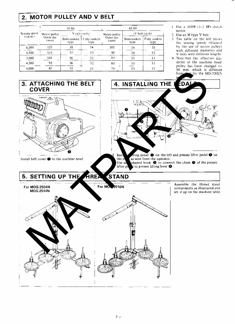
2. MOTOR PULLEY AND V BELT
Sewing 5peed Motor pulley V belt ( ~ n c h ) 1 Motor pulley . " ' " ' O u t e r *la <--~Ty-\unken Ou te r *la
/ ( m m ) I type I type (mm) I
6,000 125 38 34 1 1 0 5 1 36 3 3 I
1 . Use a 400W ( 1 / 2 W ) clutch motor .
2. Use a n M type V belt. 3 The table on t h e left shows
the sewing speeds obtaineci by the use of motor pul leys with different diameters and V belts with different lengths
4. Note that t he effective dia- meter of the machine head pulley has been changed t o 56 mm, which is different from that for the M0-2000W
4. INSTALLING THE PEDALS series.
3. ATTACHING THE BELT COVER
. - - - I
I
I
I
i 1 1 1 I
I I
Lppp- --.l
. . -~ - - ~ , I . Install starting pedal 0 o n the left and presser lifter pedal 8 on Install belt cover 0 t o the machine head. t he right as seen from the operator.
2. Use an S-shaped hook @ t o connect t he chain @ of the presser lifter pedal t o presser lifting lever 0 .
5. SETTING UP THE THREAD STAND
For MOG-2504N MOG-2514N
I For MOG-2516N Assemble the thread stand components as illustrated and set it up o n the machine table.
MATPARTS
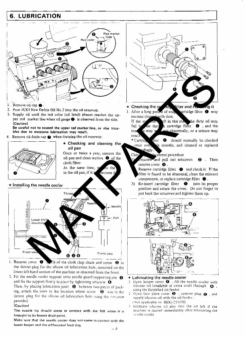
1 6. LUBRICATION I
- - 1
1. ' Remove oil cap 0 . 2. Pour JUKl New Defrix Oil No.2 into the oil reservoir. 3. Supply oil until the red color (oil level) almost reaches the up-
per red marker line when oil gauge @ is observed from the side. (Caution) Be careful not to exceed the upper red marker line, o r else trou- bles due t o excessive lubrication may result.
4. Remove oil drain cap @ when draining the oil reservoir.
-1 * Checking and cleaning the oil pan
Once or twice a year, remove the oil pan and clean section 0 of the cloth filter. At the same time, replace the oil
1 0 I in the oil pan, if it has become dirty.
* Installing the needle cooler
1-- Throat plate
mounting base
I
1 Front view
Needle
Felt
/ I I 0 0 0
Front view I 1 . Remove cover 0 (left) of the cloth chip chute and screw @ in
the detent plug for the silicon oil lubrication hole, mounted on the lower left-hand section of the machine as observed from the front.
* Checking the cartridge filter and replacing it 1 . After a long period of usage, cartridge filter 0 may
become clogged with dust. If the machine is left in this state, the dirty oil may fail t o pass through cartridge filter 0 , and the machine may wear out abnormally, or a seizure may result. * Cartridge filter 0 should normally be checked
once every six months, and cleaned or replaced accordingly.
2. Checking/replacement procedure 1) Unscrew and pull out setscrews @ . Then
remove cover Q . 2) Remove cartridge filter 0 and check it. If the
filter is found t o be abnormal, clean the relevant
2. Fit the needle cooler support onto needle guard supporting pin Q and fix the support firmly in place by tightening setscrew 0 Then, by placing lubrication joint @ between two pieces of pack- ing, attach the joint in the location where screw @ was ln the detent plug for the silicon oil lubrication hole using tile setscrew provided. (Caution) The needle tip should come in contact with the felt when it is brought t o its lowest dead point. Make sure that the needle cooler does not come in contact with the
components, or replace cartridge filter 0 . 3) Re-insert cartridge filter 0 into its proper
position and return the cover. D o not forget t o put back the setscrews and tighten them up.
- -
* Lubricating the needle cooler 1 Open looper cover 0 , fill the needle cooler with
iilicone oil (available at extra cost) through 0 , using the furnished oil feeder
2 Open fact? plate cover @ . remove plug @ , a n d upp ply s~llcone oil wlth the 011 feeder I Vot applicable to MOG-25 16N)
3 lnflltrate sllicone oil also Into the 011 felt ~f the rndchlne 1s ~tdrted ~rnrned~ately after lubrlcat~ng the nc.t.dle cooler
lower looper and the differential feed dog. 4 -
MATPARTS
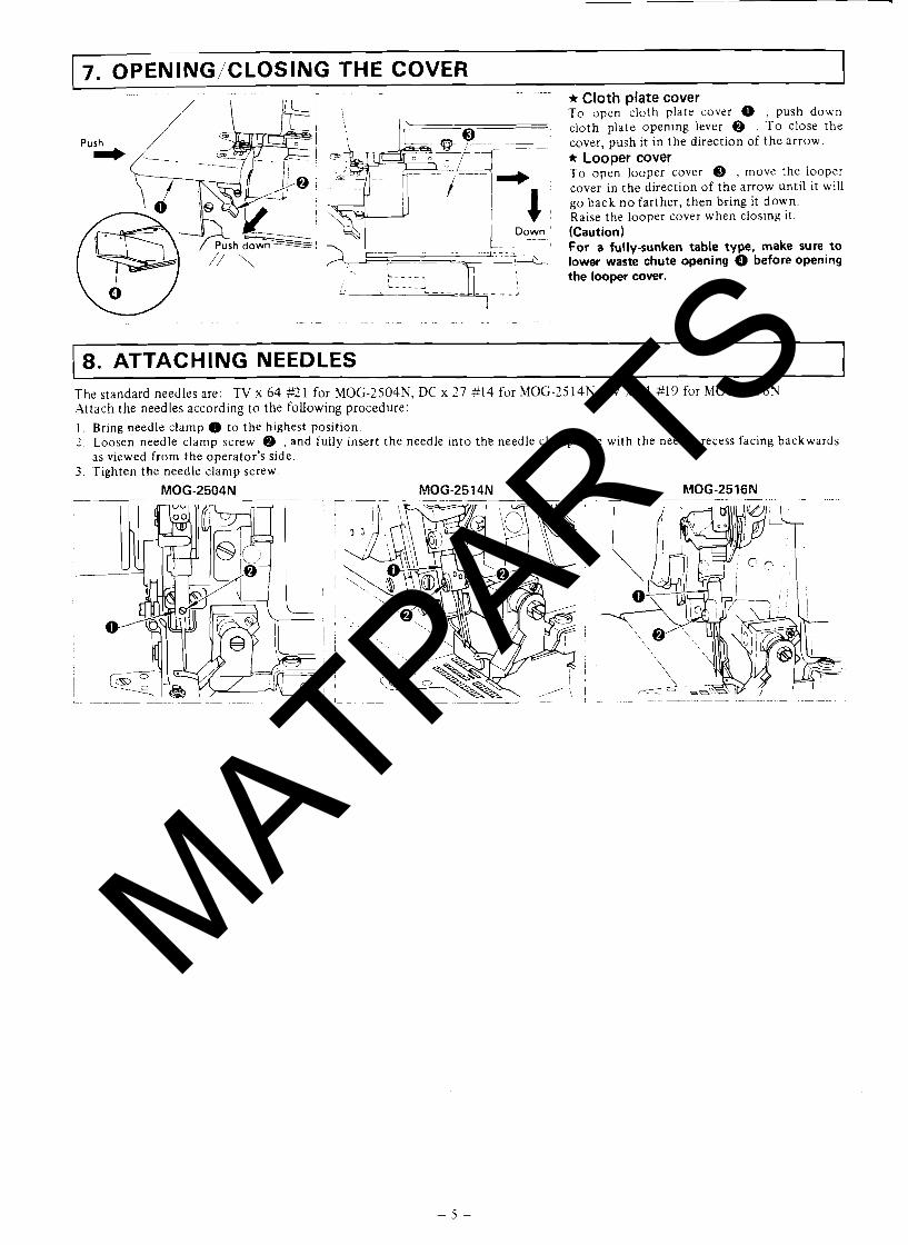
7. OPENING/CLOSING THE COVER ~~~
~~ ~- - ~- ~ - - ~ - - - ~ - - ~ ---. * Cloth plate cover ( T o open cloth plate cover 0 . push down
cloth plate opening lever @ . T o close the cover, push it in the direction of the arrow. * Looper cover
~ -- To open looper cover @ , move the looper
cover in the direction of the arrow until it will I go back n o farther, then bring it down.
\- Raise the looper cover when closing it. Down ' (Caution)
~~ For a fully-sunken table type, make sure to
,\ - lower waste chute opening Q before opening the looper cover.
I
1- - - - ~ -~ ~ - - -
8. ATTACHING NEEDLES The standard needles are: TV x 64 #2 1 for MOG-2504N, DC x 27 *I4 for MOG-25 14N. TV x 64 #19 for MOG-25 16N Attach the needles according t o the following procedure:
1 . Bring needle clamp 0 to the highest position. 2 . Loosen needle clamp screw @ , and fully insert the needle into the needle clamp hole with the needle recess facing backwards
as viewed from the operator's side. 3. Tighten the needle clamp screw.
MATPARTS
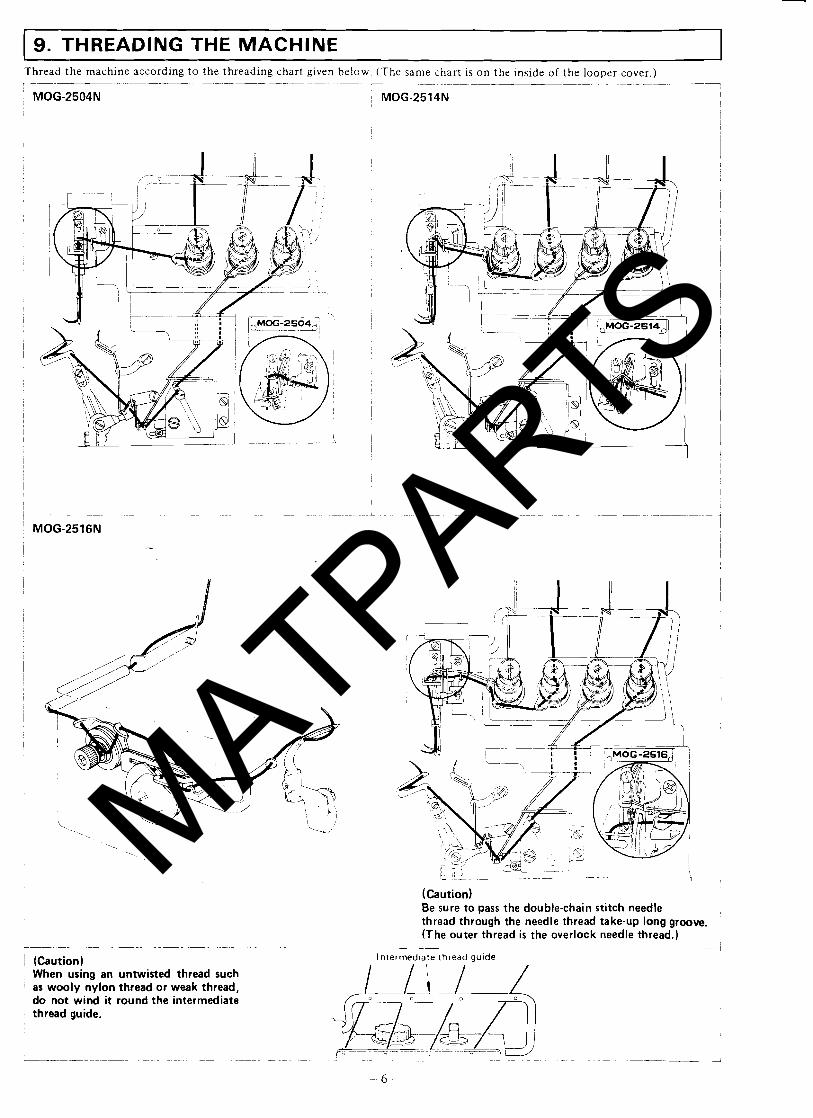
9. THREADING THE MACHINE Thread the machine according t o the threading chart given below. (The same chart is on the inside of the looper cover.) . - . . . . - - . -- - - -. - - -- . - - . - . - . - - -. - - - - 1 : MOG-2504N I MOG-2514N I
I I
(Caution) Be sure to pass the double-chain stitch needle thread through the needle thread take-up long groove. (The outer thread is the overlock needle thread.)
-~ ~~ ~ ~ - -
- i lntermed~ate thread guide (Caution)
When using an untwisted thread such ' as wooly nylon thread or weak thread,
do not wind it round the intermediate thread guide.
~~ -~ -~ ~- - - ~ - - ~ - - ~- - ~- - - - - - 2
MATPARTS
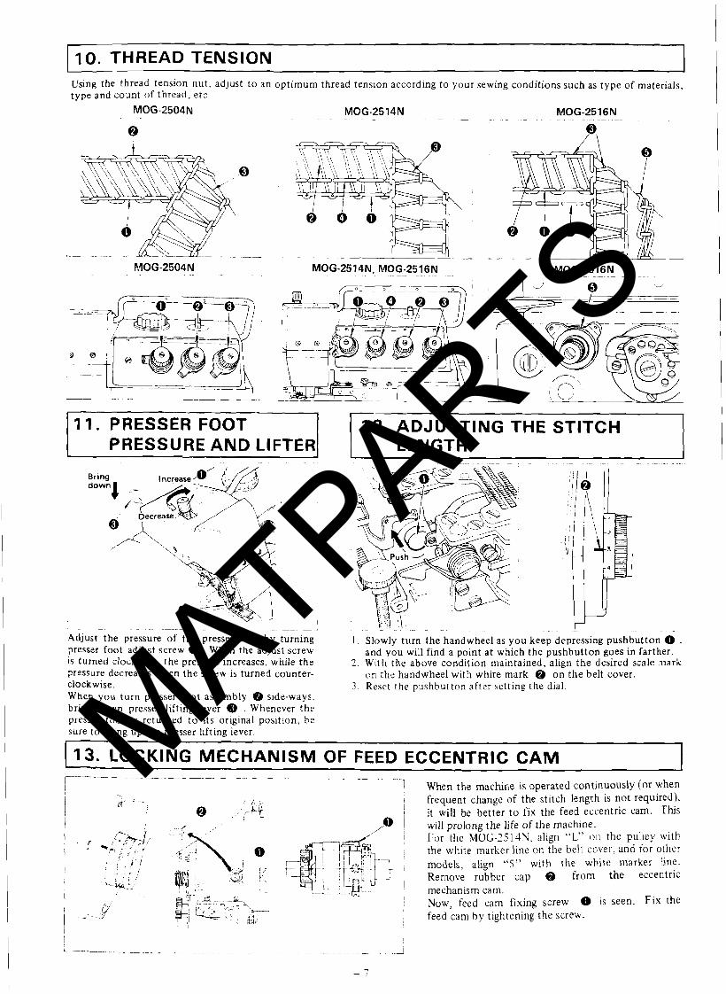
10. THREAD TENSION Using the thread tension nu t , adjust t o an opt imum thread tension according to your sewing conditions such as type of materials, type and count of thread, e tc .
11. PRESSER FOOT PRESSURE AND LIFTER
12. ADJUSTING THE STITCH LENGTH
- - ~ - ---- -~ -- -~ - - -- ~ - , . . . ~ - - ~ ~ .- ~~~ -~ - - -
Adjust the pressure of the presser foot by turning I . Slowly turn the handwheel as you keep depressing pushbutton 0 , presser foot adjust screw 0 . When the adjust screw and you will find a point a t which the pushbutton goes in farther. is turned clockwise, the pressure increases, while the 2 . With the above condition maintained, align t h e desired scale mark pressure decreases when the screw is turned counter- on thz handwheel with white mark @ o n t h e belt cover. clockwise. 3 . Reset the pushbutton after setting the dial. When y o u turn presser foo t assembly Qb side-ways. bring down presser lifting lever @ . Whenever the presser foot is returned t o its original position, be sure to bring up the presser llfting lever.
I 1
1 13. LOCKING MECHANISM OF FEED ECCENTRIC CAM -- -- .~
! <; ~,
---! When the machine is operated continuously (or when
I fr' ' - ; kj 1 frequent change of the stitch length is not required). I
I @ . . ! / it will be better t o fix the feed eccentric cam. This @ 1 will prolong the life of the machine. ' I For the MOG-25l4N. align "L" ox the pulley with
! the white marker line on the belt caber, and for other
. . . , I models, align "5" with the white marker 6ne.
1 : , , I /'
Remove rubber cap Q f rom t h e eccentric
i -, ~i -A -W 1 mechanism cam. p/' ;;-,-i -~- .,,T7 ~
>-- 1 Now, feed cam fixing screw 0 is seen. F ix the
i >*-. . ./ &: ,-- -_- ~s '-
I :/ - ' jgy 1 feed cam b y tightening the screw. 1
MATPARTS
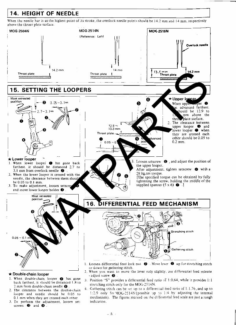
14. HEIGHT OF NEEDLE When the needle bar is a t the hghert polnt o f its stroke, the overlock needle p o ~ n t s should be 1 4 2 mm and 14 mm, respectively above the throat plate surface - - - -- - - - - - - - -- - - - -
MOG-2504N MOG-2514N MOK-2516N (Reference Left )
I I
I
I
-
1 15. SETTING THE LOOPERS 1 Most retreated I I I
* Lower looper - 1 . When lower looper 0 has gone back
farthest, it should be distanced 2.7 to 3.1 mm from overlock needle Q .
2. When the lower looper is crossed with the needle, the clearance between them should be 0.05 to 0.1 mm.
3 . To make adjustment, loosen setscrew Q and move lower looper holder @ .
Most retreated I I
I * Double-chain looper 1. When double-chain looper has gone
back farthest, it should be distanced 1.8 t o 2 mm from double-chain needle @
2. The clearance between the double-chain looper and needle should be 0.05 t o 0.1 mm when they are crossed each other.
3. To perform the adjustment, loosen set- screws @ and @ .
--
* Upper looper 1. When upper looper (b
has advanced farthest, it should be 12.9 to 13.3 m m above the throat plate surface.
2. The clearance between upper looper 0 and lower looper 0 when
' they are crossed each
other should be 0.05 t o 1 O.2mm.
3. Loosen setscrew 6 , and adjust the position of the upper looper. After adjustment, tighten setscrew B) with a 28 kg.cm torque. [The specified torque can be obtained by fully tightening the screw, holding the middle of the supplied spanner (5 x 6) @ .]
1 16. DIFFERENTIAL FEED MECHANISM I
1 . Loosen differential feed lock nut Q . Move lever 0 up for stretching stitch or down for gathering stitch.
2 . When you want to move the lever only slightly, use differential feed minute - adjust screw @ .
3. Position "S" provides a differential feed ratio oT 1 :0.64, while it provides 1 :1 stretching stitch only for the MOG-75 14N.
4. Gathering stitch can be se: up to a differentla1 feed ratio of 1 :1.76, and up t o 1 :2.9 only for MOG-25 14N (possible up to 1 :4 by adjusting the internal mechanism). The figures marked on the differential feed scale are just a rough indication.
MATPARTS
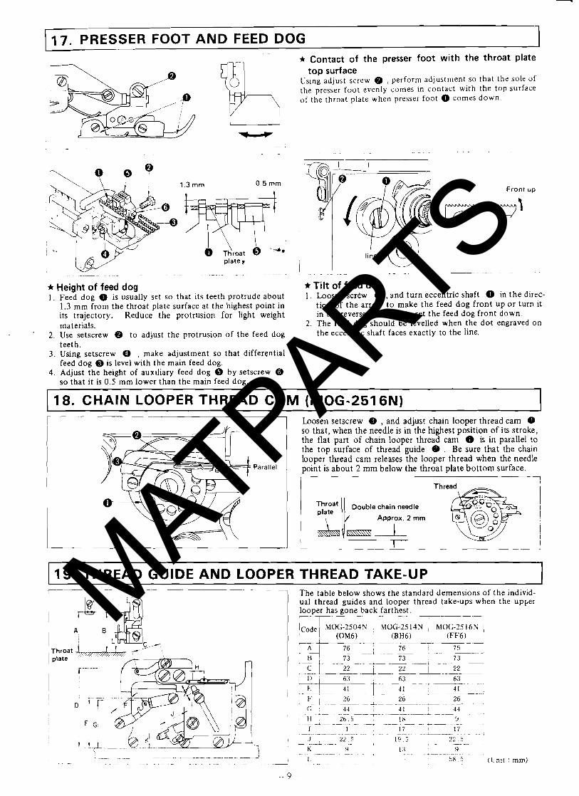
17. PRESSER FOOT AND FEED DOG 1 ~ - * Contact of the presser foot with the throat plate
top surface Using adjust screw @ , perform adjustment so that the sole c~f the presser foot evenly comes in contact with the top surface of the throat plate when presser foot 0 comes down.
* Height of feed dog 1 . Feed dog 0 is usually set so that its teeth protrude about
1.3 rnm from the throat plate surface at the highest point in its trajectory. Reduce the protrusion for light weight materials.
2. Use setscrew @ to adjust the protrusion of the feed dog teeth.
3. Using setscrew , make adjustment so that differential feed dog Q is level with the main feed dog.
4. Adjust the height of auxiliary feed dog by setscrew so that it is 0.5 rnm lower than the main feed dog.
Front up
p = Y Y 1
line ' (Q *Tilt of feed dog 1. Loosen screw Q , and turn eccentric shaft 0 in t h e direc-
tion of the arrow t o make the feed dog front u p o r turn it in the reverse direction to set the feed dog front down.
2. The feed dog should be levelled when the dot engraved on the eccentric shaft faces exactly to the line.
- 18. CHAIN LOOPER THREAD CAM (MOG-2516N)
Parallel
Loosen setscrew B , and adjust chain looper thread cam 0 so that, when the needle is in the highest position of its stroke, the flat part of chain looper thread cam 0 is in parallel to the top surface of thread guide @ . Be sure that the chain looper thread cam releases the looper thread when the needle point is about 2 mm below the throat plate bot tom surface. i--- I
Approx. 2 mrn
19. THREAD GUIDE AND LOOPER THREAD TAKE-UP The table below shows the standard demensions of the individ- ual thread gu~des and looper thread take-ups when the upper looper has gone back farthest. r 7---- I
- I-- - 1
. . __I 63 63 6 3 I
41 -- + 41
26 r.-.~ ~. . F I 26
+ - A - - - ~ -~
(; 4 4 - ~
41 !
26 1 44
1--- - ~~+ - - , H 26.5 18 9 - -I- - + . - - -~ + . J
I 1 17 17 *--.- ~ +.-. - ~ ~ ~ . ~ - - - ~ - ~ . ~ ~ ~ . ~ - - + ~ ~- - - -
J 22.5 19.5 *- ~ - & . -- ~- - + ~ - - ~~ -
2 2 . 5 + - . 1
K Y 1 :3 9 L ~ . ~ ~ . - ~ -~ .-- .* + ~- . .
1- -- ~ ~ - 5 8 . 5 (!.init : mm)
MATPARTS
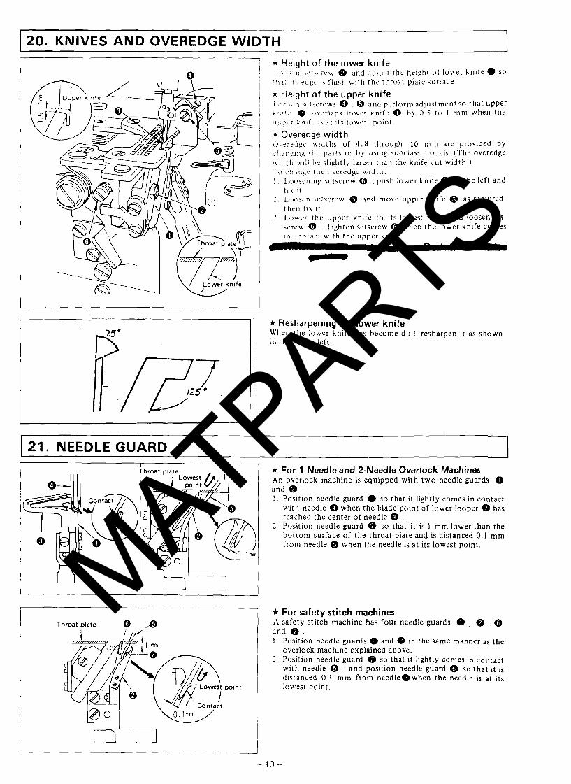
- 20. KNIVES AND OVEREDGE WIDTH
* He~ght of the lower knife I > e ,-TI .iL',< it.w and dtllust the helght ot lower k n ~ f e 0 SO
' I > \ , 11, z d g ~ $ \ tlush wlth thc throat plate \u r t a i e
* Height of the upper knife i . . r \ . ; . n ir iccrews , @ and perform adjustment so that upper A:;:!.: @ . ) \ t r l aps lower k n ~ t e 0 h y 0 5 to I rnrn when the I l i 3 p t s r k n ~ : - i , d t its lowert point
* Overedge width i he i rdg t . \+!dths of 4 . 8 through 10 rnrn dre provided by <!!-lnglilg r i ~ c parts o r b y uslng hubclaha r ~ ~ v d e l s . (The overedge u id th u~ii he slightly larger than the k n ~ f e cut width . ) P i ) <,h ingc the overedge wldth . 1 . L.ooscnlng setscrew @ , push lower knife 0 t o the left and
I 1 . x I t . 1 1.~1nsen setscrew Q and move upper knife Q as required.
t l ~ e n i ~ u i t 3 Lllwcr the upper knife to its lowest point and Loosen set-
screw @ . Tighten setscrew @ when the lower knife comes In contact with the upper knife.
* Resharpening the lower knife When the lower knife has become dull , resharpen it as shown in the figure left .
1 21. NEEDLE GUARD I ~- ~p - - - -
* For 1-Needle and 2-Needle Overlock Machines An overlock machine is equipped wi th two needle guards 0 and @ . I . Position needle guard 0 so that it lightly comes in contact
w ~ t h needle 0 when the blade point of lower looper has reached the center of needle 0
7 Position needle guard @ so that it is 1 mm lower than the bo t tom surface of the throat plate and is distanced 0 .1 'mm from needle Q when the needle is a t its lowest point.
* For safety stitch machines A safety sti tch machine has fou r needle guards 0 , @ , @ and 0 . 1 Position needle guards 0 and in the same manner as the
overlock m a c h n e explained above. 2 . Position needle guard 0 so that it lightly comes in contact
with needle @ , and position needle guard 0 so tha t it is distanced 0.1 m m from n e e d l e e w h e n the needle is at its
point 1 lowest point.
I
I
MATPARTS
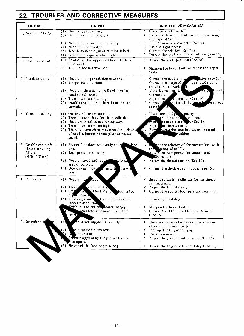
1 22. TROUBLES AND CORRECTIVE MEASURES
CAUSES 1 CORRECTIVE MEASURES I 1
Needle breaking i I I) Needle type is wrong. ! ( 2 ) h'eedle size is not correct. I
( 3 ) Needle is not installed correctly. i 4 ) Needle is not straight. ( 5 ) Keedle-to-needle guard relation is bad
- 1 t 61 Needle-to-looper relation IS bad. T - - - . .
2 , cloth Is not cut ( I ) Position of the upper and lower knife is I inadequate. / (21 Knife blade has worn out
,3 Use a specified needle. 0 Use a needle size suitable to the thread gauge
and type of fabrics. 3 Install the needle correctly (See 8). 0 Use a straight needle. 0 Correct the relation (See 2 1 ). c Correct the needle to looper relation (See 15).
~ - . -- ~ ~ - Adjust the knife position (See 20).
0 Sharpen the lower knife or renew the upper knife.
3. Stitch skipping
4. Thread breaking
( I ) Needle-to-looper relation is wrong. ( 2 ) Looper blade is blunt.
( 3 ) Needle is threaded with S-twist (or left- hand twist) thread.
( 4 ) Thread tension is wrong. ( 5 ) Double chain looper thread tension is not
enough.
( 1 ) Quality of the thread is poor. ( 2 ) Thread is too t h c k for the needle size. ( 3 ) Needle is installed in a wrong way. (4) Thread tension is too high. (5 ) There is a scratch or bruise on the surface
of needle, looper, throat plate or needle guard.
0 Correct the needle-to-looper relation (See 1 5 ) . 0 Correct the shape of the looper blade using
an oilstone, or replace it. 0 Use a Z-twist (or right-hand twist) thread witb
the needle. 0 Adjust the thread tension (See 10). 0. Correct the position of the chain looper th rea~
cam (See 18).
0 Use a thread of good quality. 0 Select a suitable needle or thread. 0 Install the needle correctly (See 8). 0 Adjust the thread tension 0 Remove scratches and bruises using an oil-
stone or buffing machine.
5 . Double chain-off thread stitcfung failure (MOG-25 16N)
6 . Puckering
7 . Irregular stitching
( I ) Presser foot does not evenly act on the feed dog.
( 2) Rear presser is shaking.
( 3 ) Needle thread and looper thread tensions are not correct.
( 4 ) Double chain looper is installed in a wrong way
( 1 ) Needle is too thick
Thread tension is too high. Pressure applied by the presser foot is too high or too low. Feed dog comes up too much from the throat plate surface.
( 5 ) Knife fails t o cut the fabrics sharply. (6) Differential feed mechanism is not set
correctly.
( 1 ) Thread is not supplied smoothly. 1
0 Correct the relation of the presser foot with the feed dog.(See 17).
0 Adjust the rear presser for smooth and steady motion.
0 Adjust the thread tension (See 10).
0 Correct the double chain looper (see 15).
0 Select a suitable needle size for the thread and materials.
0 Adjust the thread tension. 0 Correct the presser foot pressure (See 1 1 ) .
0 Lower the feed dog.
0 Sharpen the lower knife. 0 Correct the differential feed mechanism
(See 16).
0 Use smooth thread with even thickness or
( 2 ) Thread tension is too low. (3 ) Needle is blunt. (4) Pressure applied by the presser foot is
inadequate. ( 5 ) Height of the feed dog is wrong.
clean up the thread path. 0 Increase the thread tension. 0 Use a new needle. 0 Adjust the presser foot pressure (See 11).
0 Adjust the height of the feed dog (See 17). MATPARTS
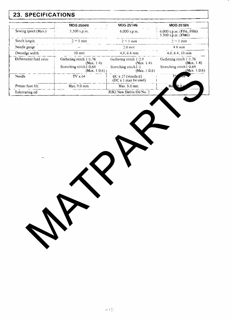
23. SPECIFICATIONS
MOG-2504N MOG-2514N MOG-2516N ~ ~ ---- ~ ~
Sewing speed (Max.) I 5,500 s.p.m. 6,000 s.p.m. 6,000 s.p.m. (FF6, FH6) 1 5,500 s.p.m. (FM6) -.L- ---- - - - - - - _ - --_ _ . _ __
Stitch length 2 - 5 mm 2 - S m m 2 - 5 m m --- - - - .- .. a-- -- _ - Needle gauge I 2.0 rnm 4.8 mm
-- - -*-.-- ---
Overedge width 10 rnm 4.8,6.4 mm 4.8.6.4, lOmm
Differential feed ratio I Gathering stitch 1 : 1.76 i Gathering stitch 1 :1.76 (Max. 1 :4) (Max. 1.4) 1 (Max. 1 14)
i Stretching stitch 1 :0.64 Stretching stitch 1 :0.64
Needle
-
Presser foot lift
Lubricating oil
(Max. 110.6) 1 (Max. 1 :0.6) 1 (Max. 1 :0.6) --
TV x 64 1 DC x 27 ( s t a n d a r y i TV x 64 1 (DC x I may be used) (
Max. 9.0 mm -f-- Max. 8.0 - T Max. 9.0 mm
JUKI New Defrix Oil No. 2
MATPARTS
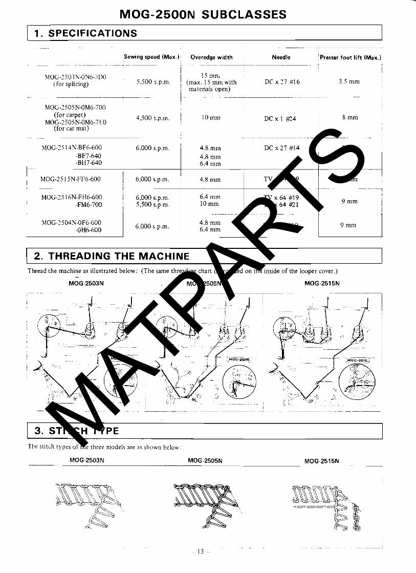
MOG-2500N SUBCLASSES
1. SPECIFICATIONS
Sewing speed (Max.) Overedge width Needle :Presser foot lift (Max.)
I MOG-2503N-ON6-3D0 15 mm
(for splicing) I 5,500 s.p.m. (max. 15 mrn with ~ DC x 27 #I6 ~ materials open) 1
, (for carpet) I 4,500 s.p.m. MOG-2505N-OM6-7E0 i
I (for car mat) I ~ ~
2. THREADING THE MACHINE Thread the machine as illustrated below: (The same threading chart is provided on the inside of the looper cover.) -
MOG-2503N MOG-2505N MOG-2515N
3. STITCH TYPE The stitch types of the three models are as shown below:
MOG-2503N MOG-2505N
MATPARTS
4. A
DJ
US
TM
EN
TS
OF
NE
ED
LE
HE
IGH
T A
ND
LO
OP
ER
TIM
ING
1
I 1
r!
rn
I
I
.
1 % 0
- .-
l i n
c! i
n;
i
N
Q 3 .E g.; 0
"O
U
~5
.2
2
U)
U)
jU
)l
i
i
1 _
__
I-L
A-.-
~
i $ 9 n
s, Z
cE
E
a.2
gz
:-%
Eo
s!~
L
VI - 3
z 1
9
- I
2
g&
cZ
-
t
w
w
-
'+. w
w
-
& g 4
I 1
gg
25
30
4
22
22
h
e, b
g$
+u
w3
, 30s %
$
2 I
2 / a 1
a ;
I !
11
1 I
:
hh
h
0-
22
2
WN
C(
o* O*
8
o
2 0
-
--.I
I 1
;"!'a
jL
A
,L
O
( v,
1
I -+ +
---
~
1 -
8 ZZ
.-
4
i-
-
;"
?
aa
~
a g
'~
2 -
G
- C
;
+
,m
d
,
+ ;
&
..-. 3
-r
. -
I -
;--A7-
~ :
e, -
! 0
I /
,,
I ?----.-.
*
I I
I IP
l
iC
4
N
;u
;; 2
I.
.
a-
I
E
/'
/ '
ia!q
-cu
l q..1!1< i~r
jip
_____-i
- _
__
* 3
-
1
I i
G!
1
I z
;
-
r
w
b*
LZ
a
wa
us
@
8%
3
A 32s u+
wr
m
B.2
2
a.z
@
U
ma
z g
.c
i.
9
@
GZ
2
' 1
*X
*X
3
*
3
4
VV
V
h
- WO
G$
m
w
?-
d
- V
, --
9 ;
z9
;
A
Ww
W
I ,
! I
39
,
I -r
u
! ;
LO
,
e!
. -- -
- N
N
- I.?$ r-m
m
m
I ,
- - - -
I S
j =
. --...
-
i i
I:
3
2 N
ip? iz
~2 i
* i
d
i I
I I
t-+ - +
2 im '
y
i I a
I s
!
a
I&
/
od
*
* I
*
i.
3 lc, ~
MATPARTS
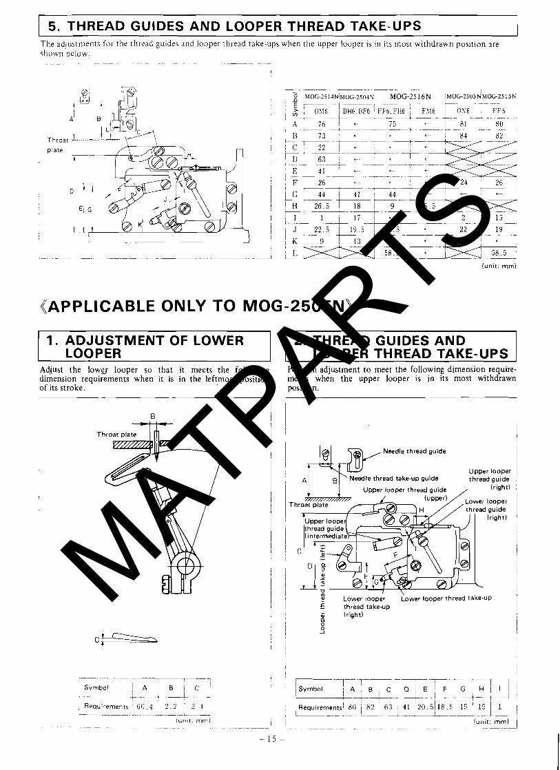
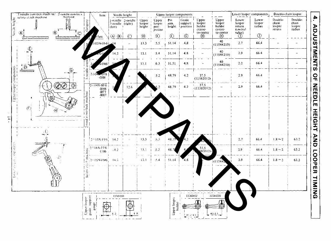
5. THREAD GUIDES AND LOOPER THREAD TAKE-UPS The adjustments for the thiead guides and looper thread take-ups when the upper looper is in its most withdrawn position are shown below:
- ~- - - -- - - ~ -- - ~ -
Throat
plate
I 1 ' 2 i l _-_i-- 15 - 1
+ 22 i 19
(unit: rnm)
((APPLICABLE ONLY TO MOG-2505N)
1. ADJUSTMENT OF LOWER LOOPER
Adjust the lower looper so that it meets the following dimension requirements when it is in the leftmost position of its stroke.
2. THREAD GUIDES AND LOOPER THREAD TAKE-UPS
Perform adjustment t o meet the following dimension require- ments when the upper looper is in its most withdrawn position.
Needle thread guide i I 1
I Upper looper 1 I A Needle thread take-up guide thread guide
1 - I Upper looper thread guide / (right) /
I m ' \ I Lower looper Lower looper thread take-UP I 5 thread take-up l
(right) d l 9
MATPARTS
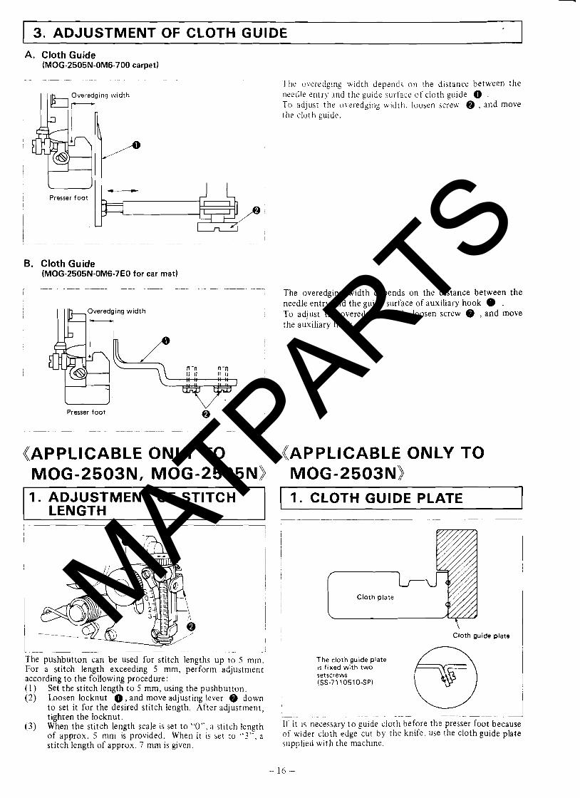
3. ADJUSTMENT OF CLOTH GUIDE A. Cloth Guide
(MOG-2505N-OM6-700 carpet)
Overedging width
The overedging width depends on the distance between the needle entry and the guide sur-face of cloth guide 0 . To adjust the overedgil~g widtll, loosen screw @ , and move the cloth guide.
Presser foot I
I
B. Cloth Guide (MOG-2505N-OM6-7E0 for car mat)
Overedging width I I Ib,
Presser foot v
I 0
((APPLICABLE ONLY TO MOG-2503N, MOG-2505Nj) 1. ADJUSTMENT OF STITCH
LENGTH
The overedging width depends on the distance between the needle entry and the guide surface of auxiliary hook 0 . To adjust the overedging width. loosen screw 9 , and move the auxiliary hook.
((APPLICABLE ONLY TO MOG-2503Nj) 1. CLOTH GUIDE PLATE I
The pushbutton can be used for stitch lengths up to 5 mm. For a stitch length exceeding 5 mm, perform adjustment according t o the following procedure: (1) Set the stitch length t o 5 mm, using the pushbutton. (2) b o s e n locknut 0 , and move adjusting lever @ down
to set it for the desired stitch length. After adjustment, tighten the locknut.
(3) When the stitch length scale is set t o "0". a stitch length of approx. 5 mrn is provided. When it is set to " 3 " , a stitch length of approx. 7 mm is given.
Cloth guide plate !
The cloth guide plate is fixed with two setscrews (SS-7110510-SP)
~ - .. ~ . . - - ~ - -- .- ->
If it is necessary t o guide cioth before the presser foot because of wider cloth edge cut by the knife. use the cloth guide plate supplied with the machine.
MATPARTS
JUKI
PARTS BOOK
Manulacturm of lndustrlal M n g Machlne Anochmenfs,
Parfs and Equipment
model MOK-2516-FF6-600 .
SEWING MACHINE AllACHMENTS CO., INC. - B & W MANUFACTURING, OlVlSION OF C 6 W ATTACHMENTS CO.
140 58th STREn. BAT. I B ; BROOKLYN, ~kf YORK 11220 *718492-9177. FAX: h8492-1000 U.S A 800-$37-5118 CANADA 800423-7776
MATPARTS
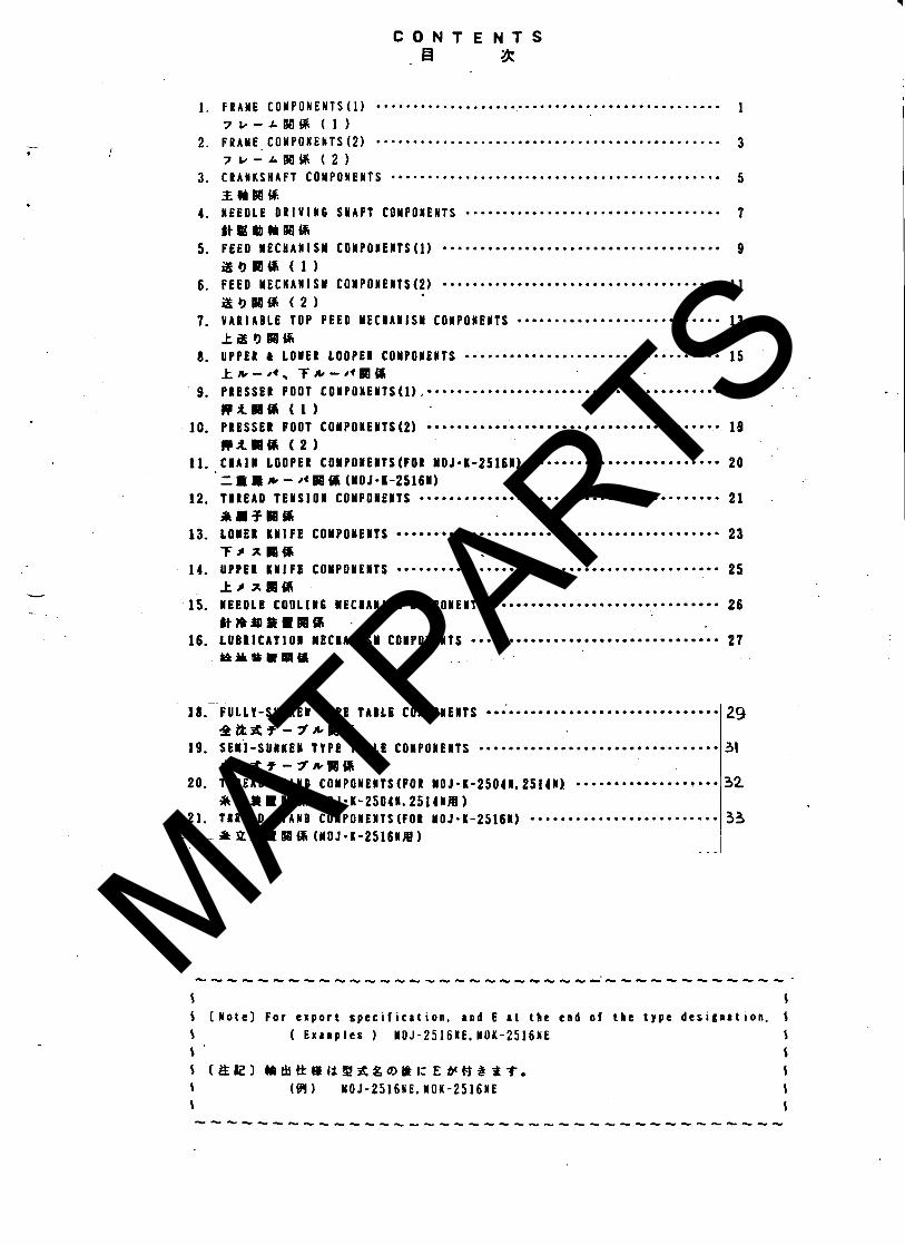
C O N T E N T S . EI1 a
.............................................. 1. F R A Y E C O Y P O N E N T S ( 1 ) 1 7 I / - L B a % ( 1 1 .............................................. 2. F R A Y E . C O W P O N E N T S ( 2 ) 3
7 k - A B a M ( 2 ) 3- C R A Y K S H A F f C O Y P O N E N f S ...........................................a 5
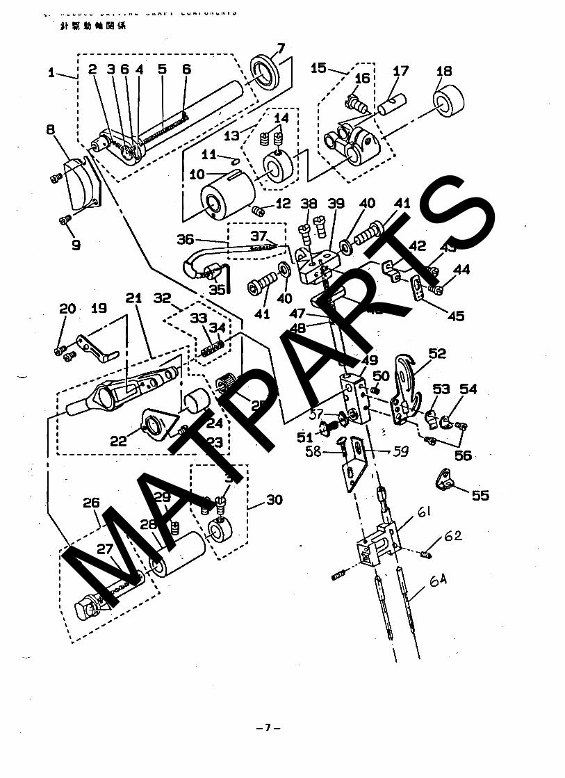
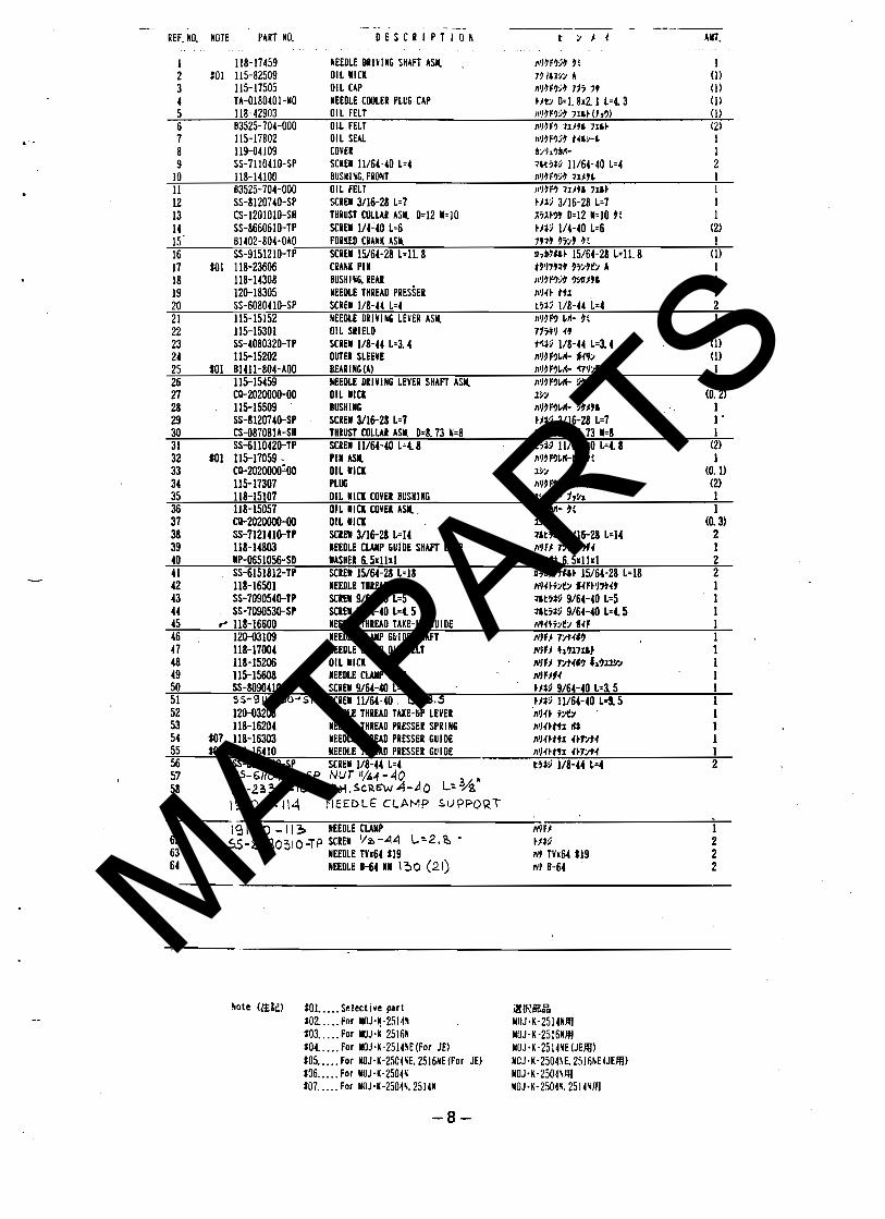
Z(lBB% 4. N E E D L E D R I V I N 6 S # A F T COMPONENTS .................................. 7
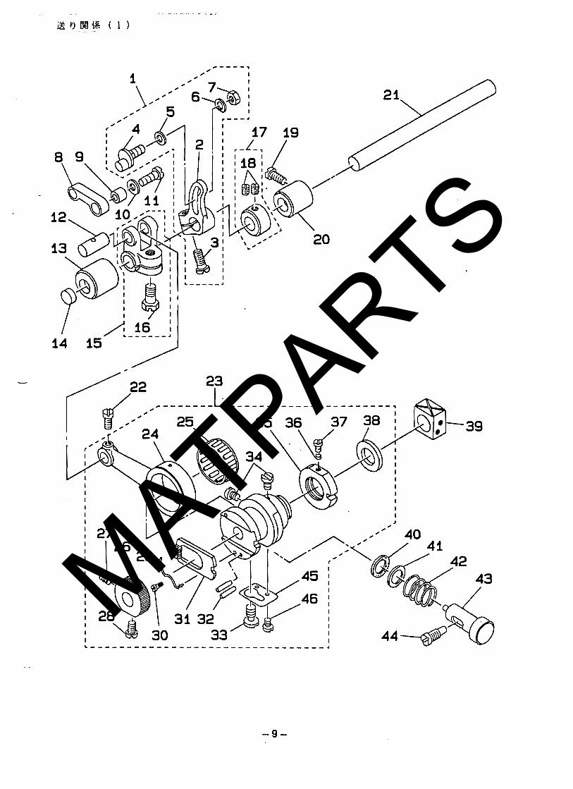
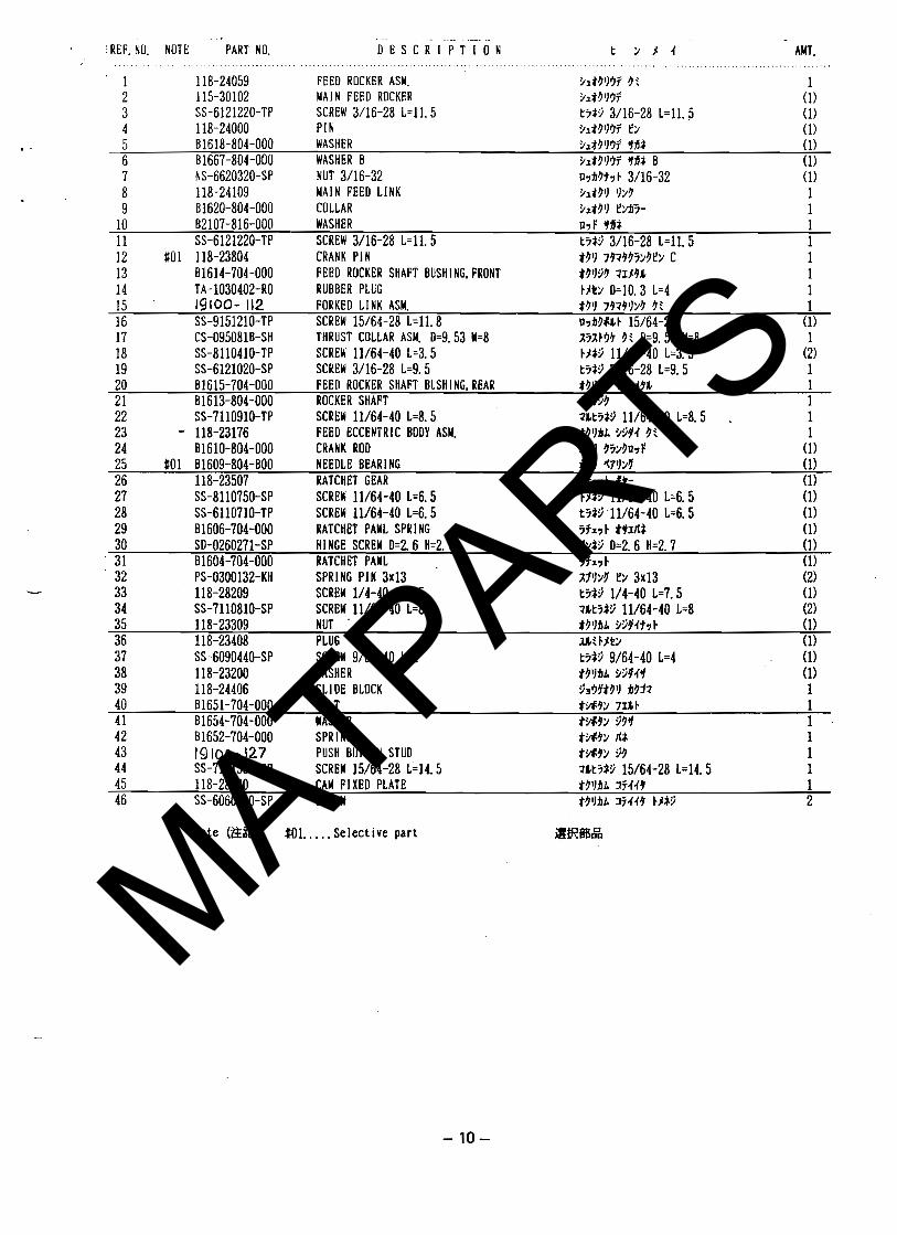
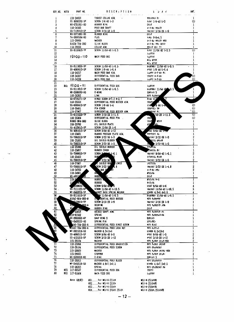
I t@tbYW6% ..................................... 5. P E E D M E C h A N l S M COMPONEWTS(1) 9
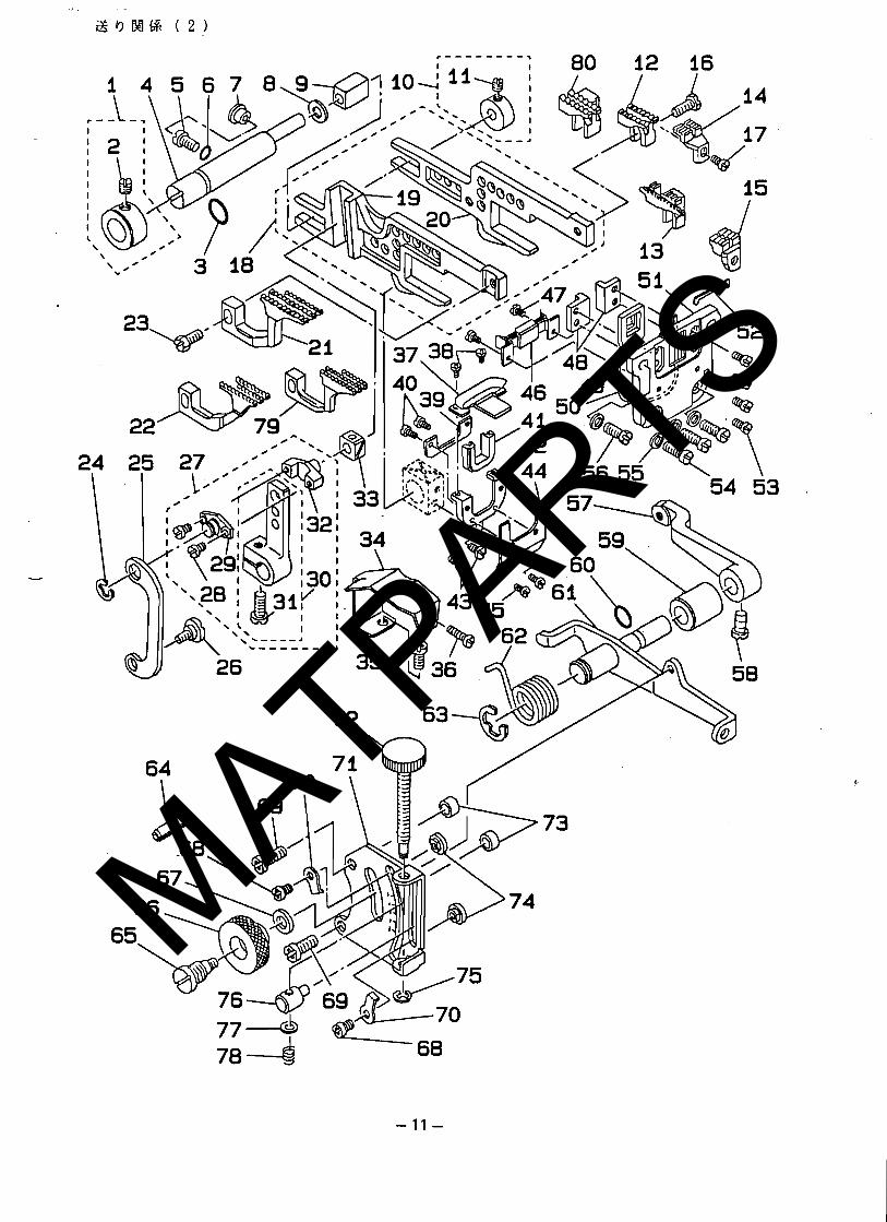
t ! ,WCTi ( 1 ) 6. F E E D M E C H A N I S M C O M P O N E W t S ( 2 ) ..................................... 11
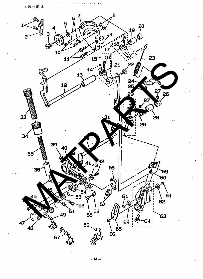
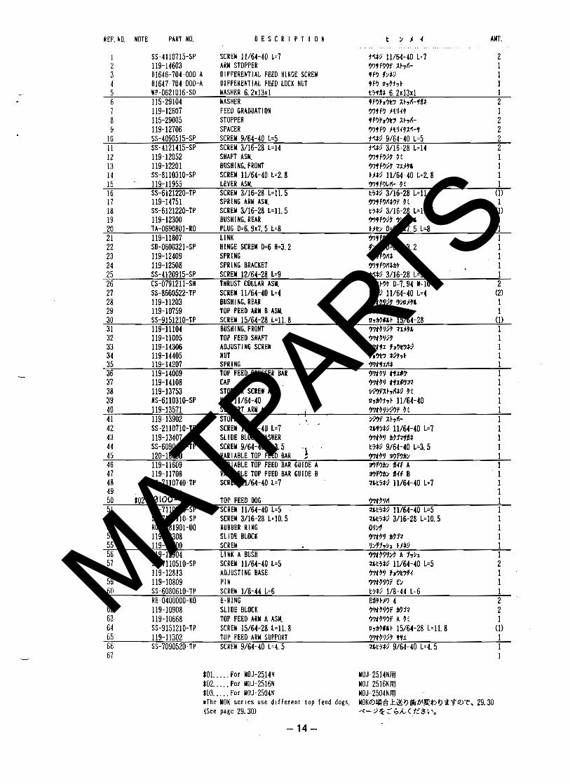
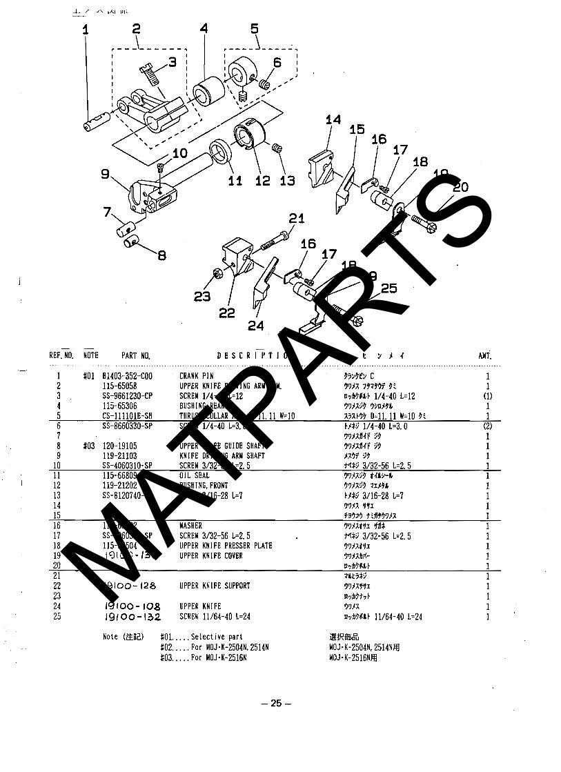
t c J m i a ( 2 ) 7. V A R I A B L E T O P P E E D M E C N A N l S Y COMPONENTS * * = a * * * * * * * * - * - * - * * . * * * * * * - 13
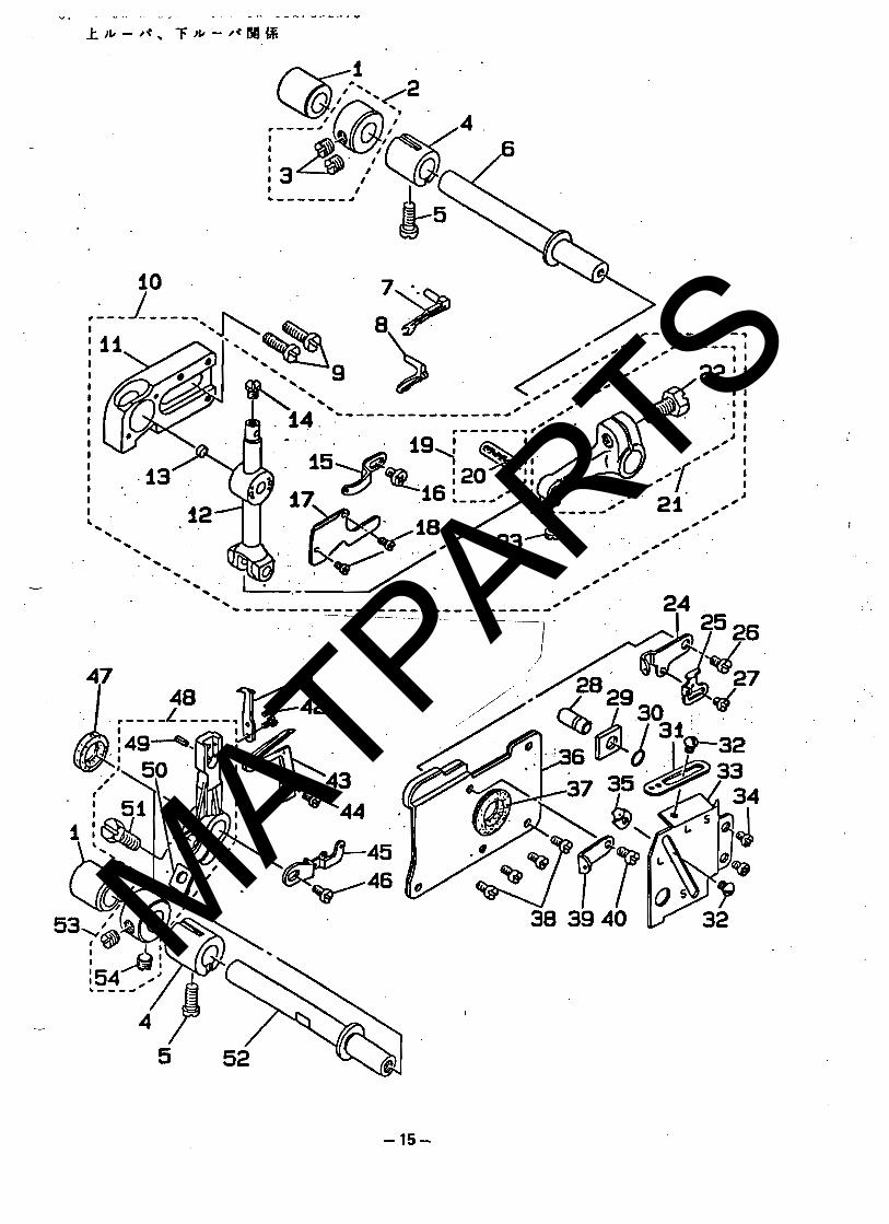
+ t r ) m 6 % 8. U P P E R LOWER L O O P E R COMPOWENTS .................................. 1s
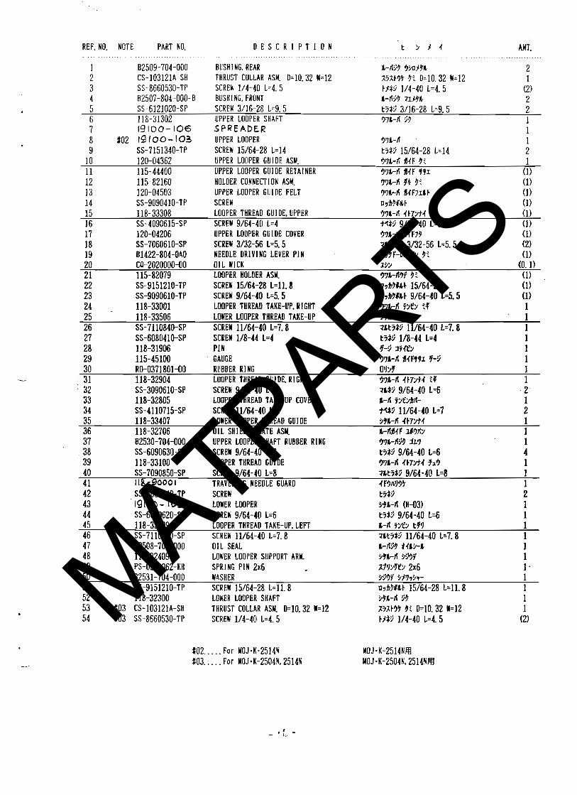
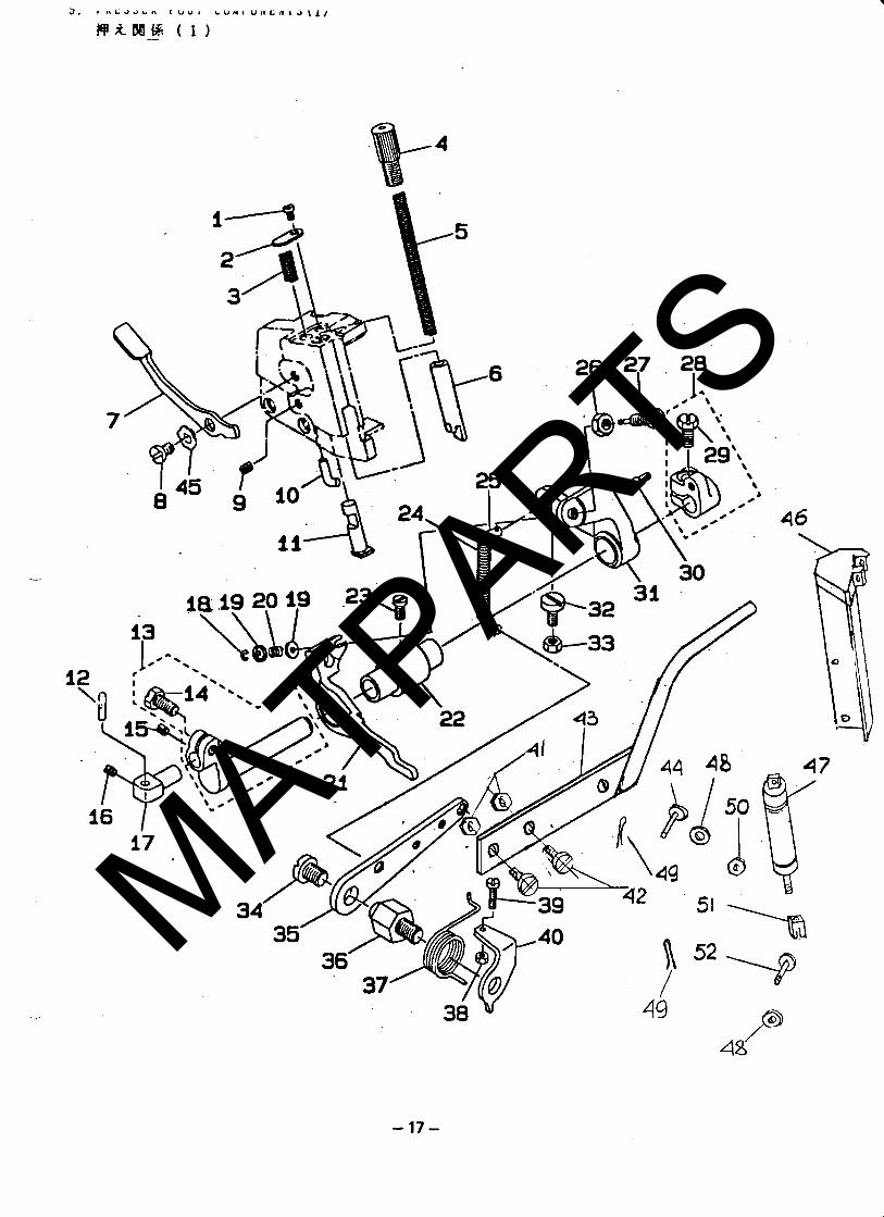
k * - A . +*-,*as 9. PRESSER p o o l CO~~OYEWTS(~),...............-....................... 17
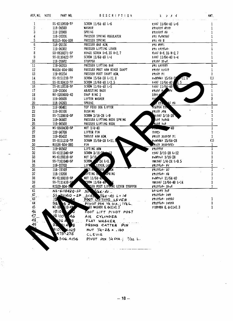
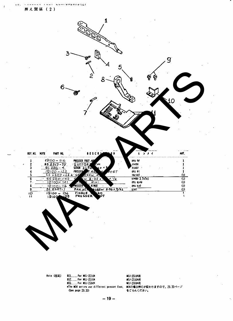
R A W % ( I ....................................... 10. P R E S S E R F O O T C O M P O N E Y T S ( 2 ) 18 4vAW4-6 ( 2 )
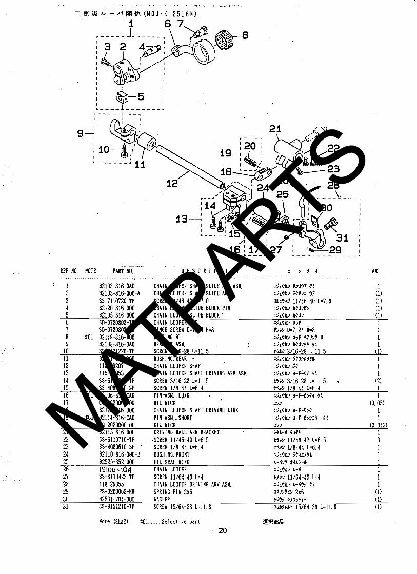
If. C I A 1 1 L O O P E R C O Y P O I E U T S ( F 0 R M O J * K - 2 5 1 6 N ) * * - * - * * * - * * - - * = * * * * * - * - * * 20 I= l * - ,* W % ( M 0 J . I - 2 5 1 6 1 )
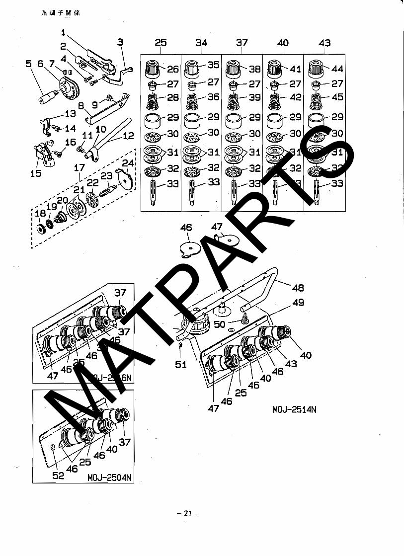
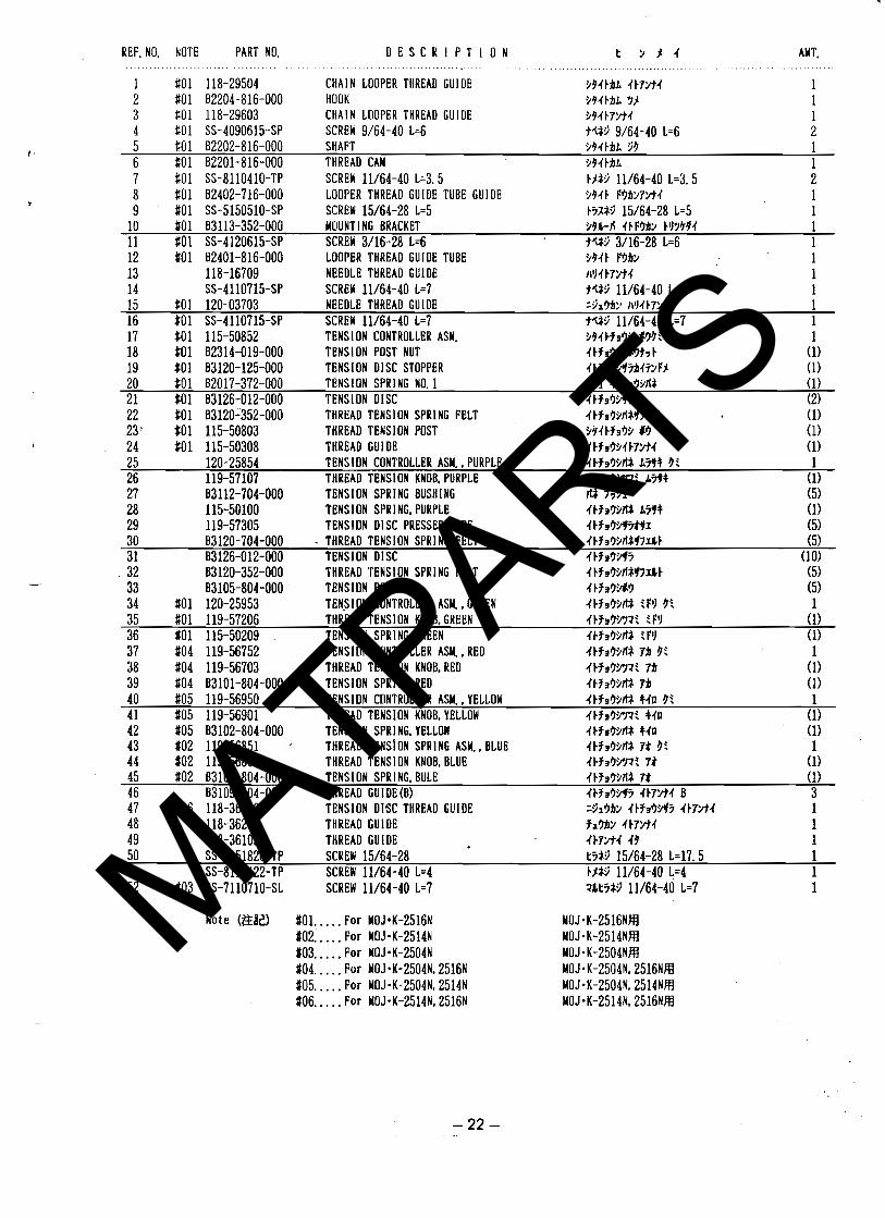
12. T f i R E A D T E M S l O N COMPONENTS ........................................ 2 1 &131W%
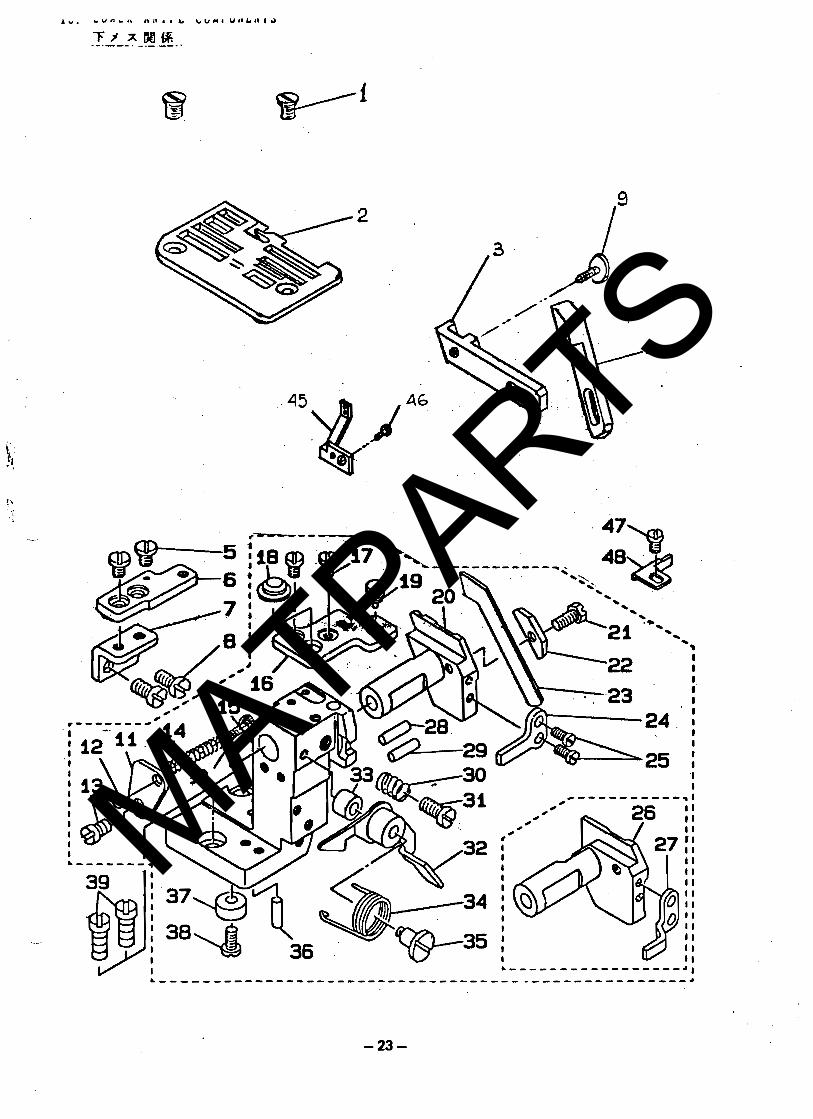
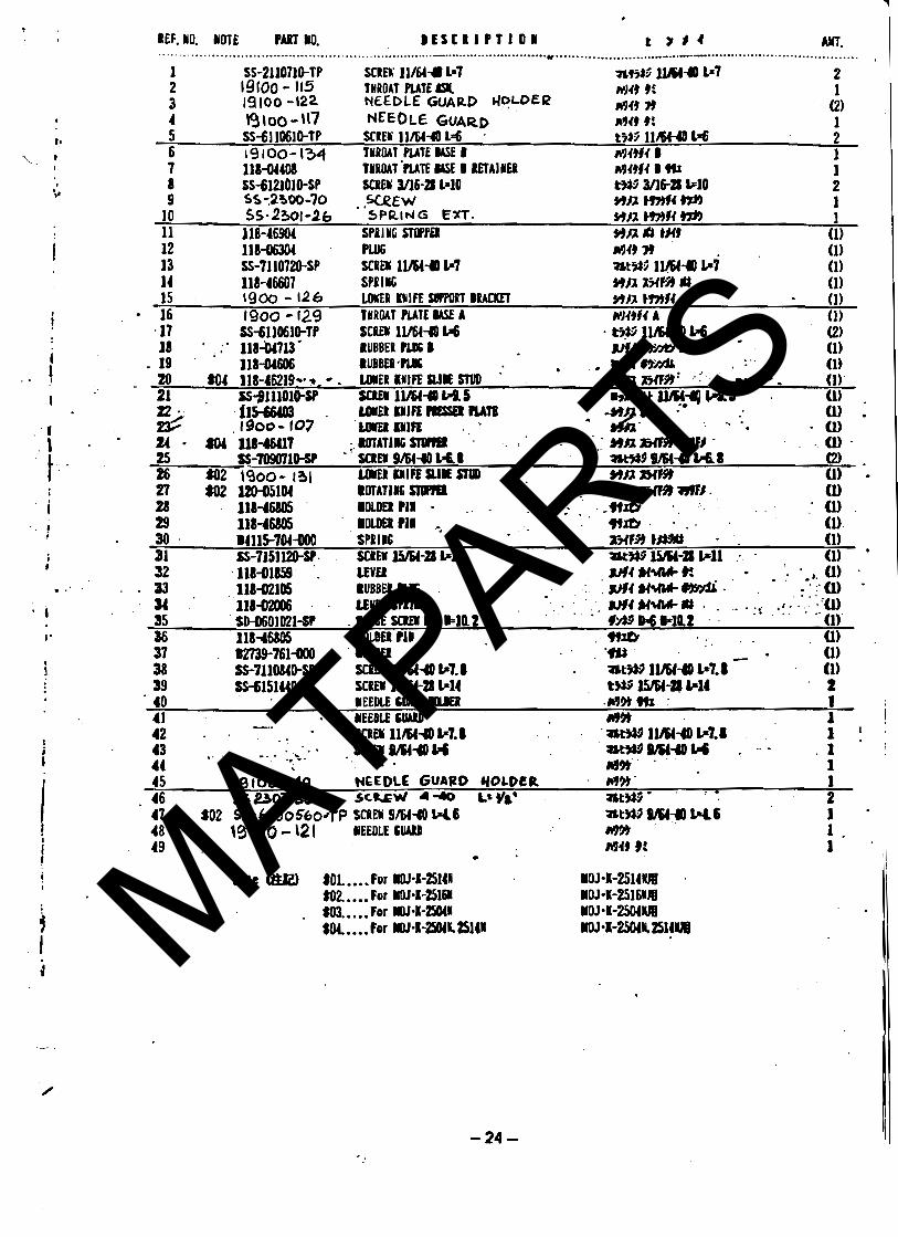
13. Lore, ~MIFE c o w p o N ~ N ~ s ........................................... 23 -Fs x 8 8 1
14. U P P E R KNIFE C O M P O l E W T S ......................................... 2 5 + s
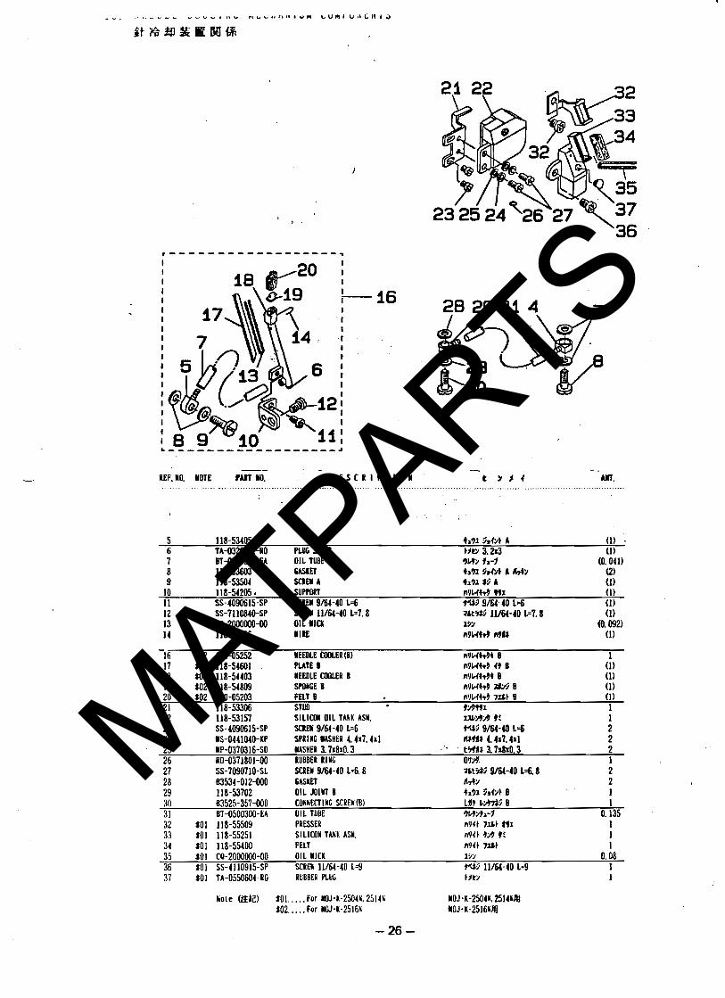
15. N E E D L E C O O L I N 6 W E C I A N I S I COMPONENTS * * - * * - * - - * * * - * * * - * - - - * - - * - - * - - 2 6 LtBarmWIR .
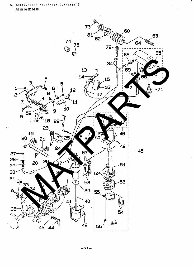
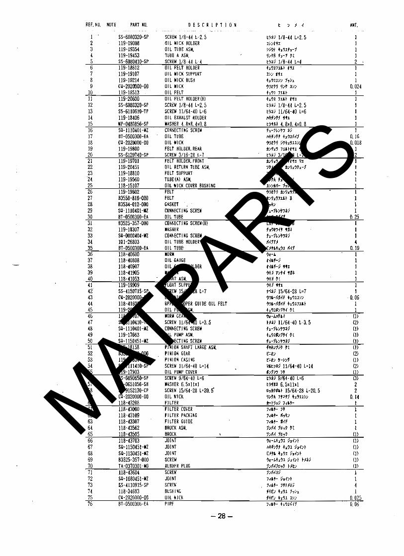
16. L U B I l C A T l O 1 I E C l A M l S M C O I P O W E W T S - - - * * * - * * - * - ~ " - * * * * * - * * * - - * - * - = = ~ 2 7 142LPlMQ;
Z - 5 L L - C - C 5 5 ~ - C C S C ~ ~ 5 5 5 Z C 5 5 L ~ 5 C 5 C C 5 5 - . c L I C C
\ I \ [ N o t e ) F o r e x p o r t s p e c i f i c a t i o n , a n d E a t t h e e n d o f t h e t y p e d e s i l n a t i o n . I \ ( E x a m p l e s 1 Y O J - 2 5 1 6 N E . Y O K - 2 5 1 6 N E I I 1 I [ S K I Y t b t k C I i t B A % O l l t i : E S H S $ t . I \ (B) M O J - 2 5 1 6 K E . Y O K - 2 5 1 6 N E \ I \ - - - - - - - - - - c - - - - - 5 - - - 5 - - - - c - - - - C - - - - - - - -
-
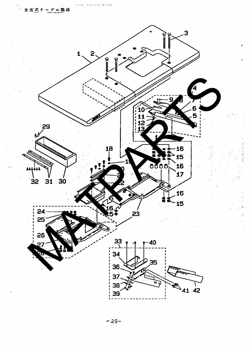
l a . FULLI-SUNKEN T Y P E TABLE COWPONEITS - - - - - ~ - - ~ ~ ~ ~ ~ - - " = ~ ~ ~ - - ~ = g ~ ~ - - w -
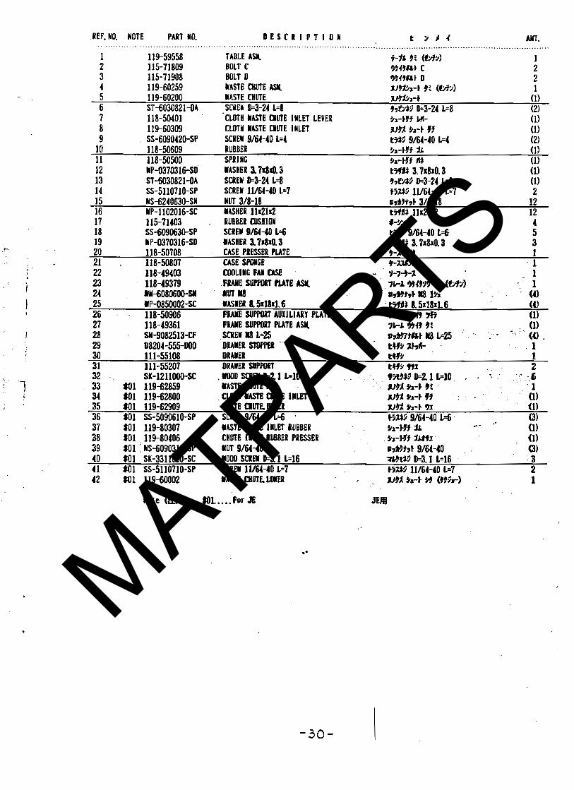
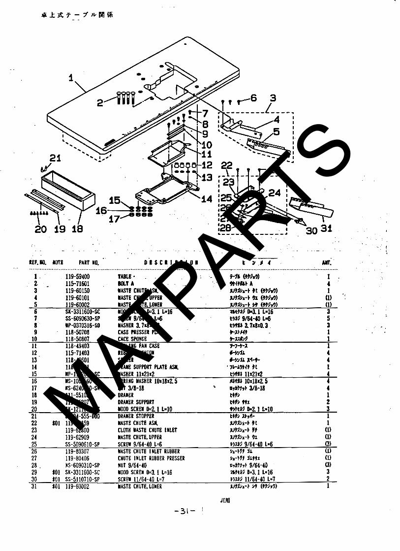
* t t f t t - l * W I B 19. S E M I - S U N K E N T Y P E T A B L E COMPOWEWTS - * * * - * - * - * * - - - * - * * - * - * * * - * - * - - * -
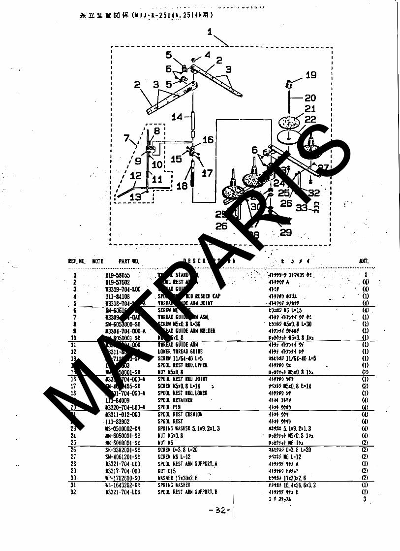
*+&t -l*l4-6 20. T N R E A D S T A N D C O M P O N E N T S ( P 0 R M O J . I ( - 2 5 0 4 1 , 2 5 1 4 W ~ - - - - * - * - * - * * * * * * * - *
S R M 6% ( I O J - K - 2 5 0 4 r . 2 5 1 4 W f l )
29
31
32
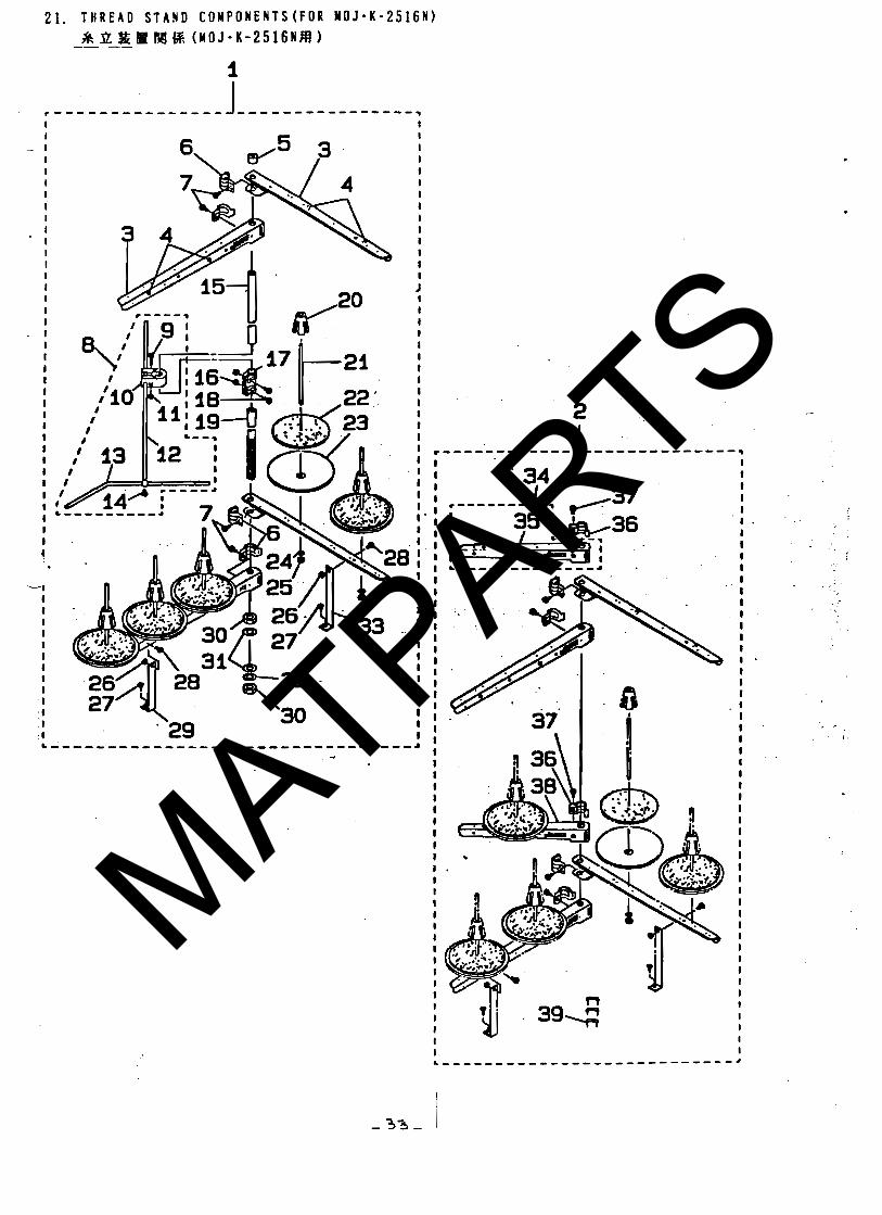
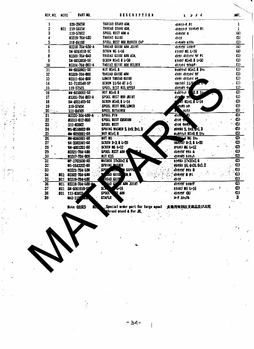
21. T I R E A D S T A N D COMPOWEWTS(F0R M O J - K - 2 5 1 6 1 ) - - * * * * - - . - * * * * - - * * * - * * * - *
- - - a 2% R Bd fi ( M O J * K - 2 5 1 6 1 N ) - - - ! 33
MATPARTS
MATPARTS
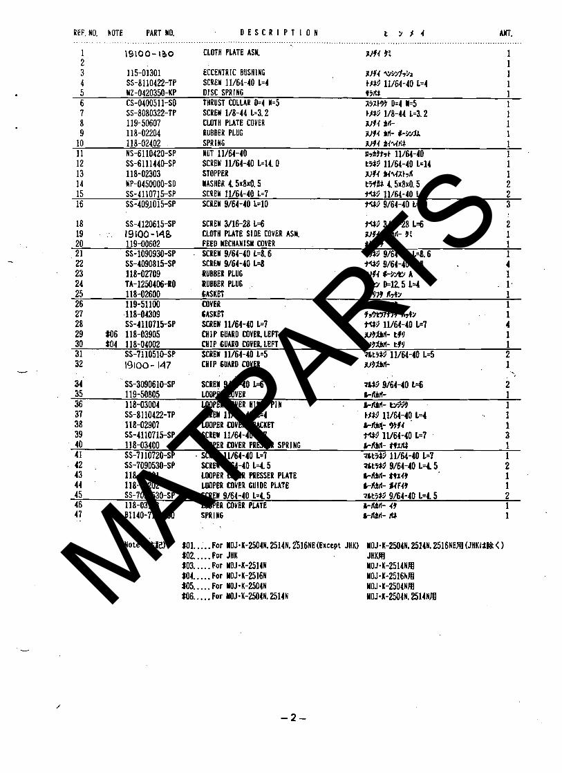
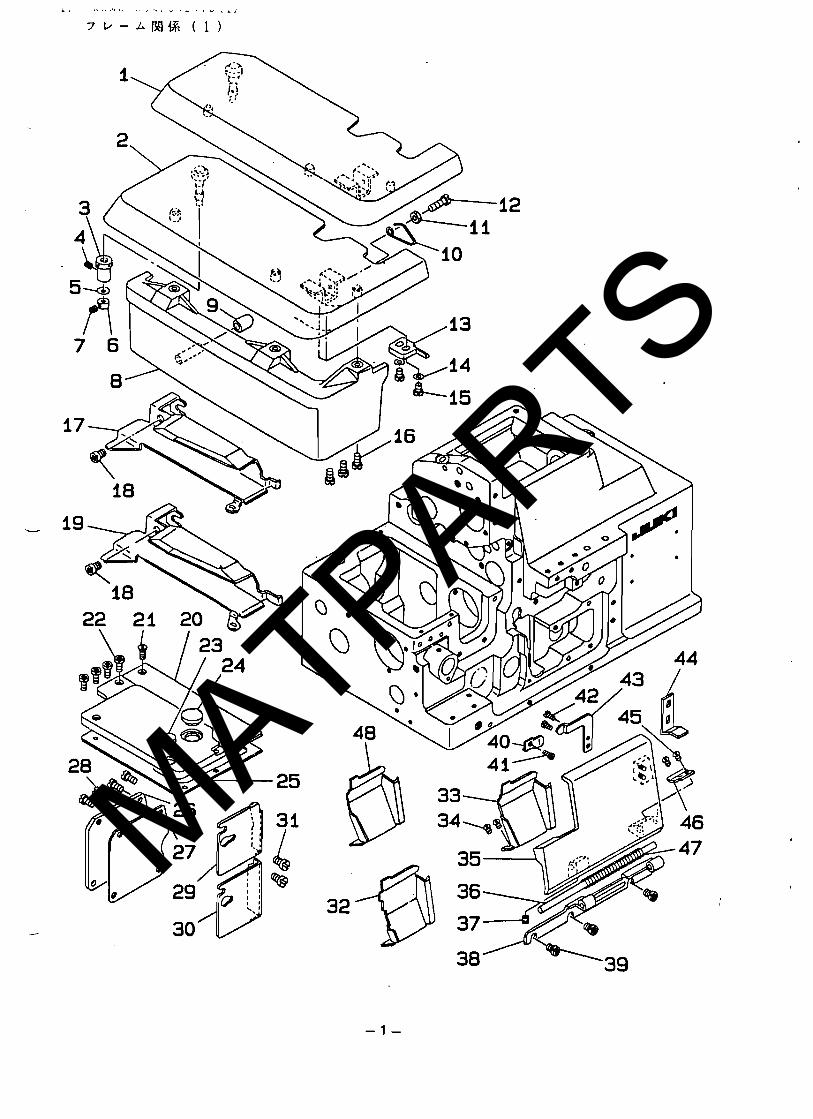
REF. 10. NOTE PART NO. D E S C R I P T I O N t Y $ 4 Am. .. . . - . . .
1 19100- 130 CLOTH PLATE ASM. 3194 9: 1 2 1 3 115-01301 ECCENTRIC BUSHING 3194 WW791 1 4 SS-8110422-TP SCREW 11/64-40 L=4 t#P 11/64-40 L=4 1 5 WZ-0420350-KP DISC SPRl NG t y f f 1 6 CS-0400511-So THRUST COLLAR D=4 W=5 I(ilE99 D=4 W=5 1 7 SS-8080322-TP SCREW 1/8-44 1.3.2 t#$3 1/8-44 Lz3.2 1 8 119-50607 CLOTH PLATE COVER jV44 Itt- 1 9 118-02204 RUBBER PLUG 3194 Itt- #-?A 1
10 118-02402 SPR l NG 3144 h 4 q a 1 11 NS-6110420-SP NUT 11/64-40 ~ 7 L J t r t 11/64-40 1 12 SS-6111440-SP SCREW 11/64-40 L=I4 0 13 118-02303 STOPPER 14 UP-0450000-SD NASHER 4. 5 ~ 8 ~ 0 . 5 15 SS-4110715-SP SCREW 11/64-40 L=7 +W 11/64-40 L=7 2 16 SS-409J015-SP . SCREW 9/64-40 L=10 Wi; 9/64-40 L=10 3
SS-4120615-SP SCREN 3/16-28 L=6 1 9 1 0 0 -148 CLOTH PLATE SIDE COVER ASY.
20 119-00602 FEED MECHANISM COVER tg' l7t 1 2 1 SS-1090930-SP . SCREW 9/64-40 14.6 W 3 9/64-40 1~8 .6 1 22 SS-4090815-SP SCREW 9/64-40 L=8 +W 9/64-40 L=8 4 23 118-02709 RUBBER PLUG WJI4 4-Y& A 1 24 TA-1250406-BO RUBBER PLUG .. I/& D.125 L=4 . 1. 25 118-02600 GASKEl $3979 a 7 b 1 26 119-51100 COVER f r 3 m t 7 9 1 27 .118-04309 GASKET 28 SS-4110715-SP SCREW 1V64-40 L=7 29 M 6 118-03905 CHIP GUARD COVER, LEFT 30 $04 118-04002 CHIP GUARD COVER LEFT WJMtt- t9'l 1 31 SS-7110510-SP SCREW 11/64-40 L=5 71tiS3 11/64-40 L=5 2
CHIP GUARD COVER
34 SS-3090610-SP SCREW 9/64-40 L=6 ?hu 9/64-40 L=fi 2 35 119-50805 LOOPER COVER hlbtt- 1 36 118-03004 UIOPER COVER UllGE PIN . h - 3 1 37 SS-8110422-TP SCREW 11/64-40 L=4 I$*> 11/64-40 14 1 38 118-02907 U)[)PER COYER BRACKET blbd- 9994 1 39 SS-4110715-SP SCREW 11/64-40 L=7 ?UP 1V64-40 L=7 3 40 118-03400 LOOPER COVER PRESSER SPRING S-lbd- HI# 1 41 SS-7110720-SP . SCREW 11/64-40 L=? ?$ti&> 11/64-40 L=7 1 42 . SS-7090530-SP SCREW 9/64-40 14. 5 ?&ti*> 9/64-40 L 4 5 2 43 118-03301 LOOPER COVER PRESSER PLATE blbfi- H149 1 44 118-03202 MOPER COVER GUIDE PLATE IblbA d4f49 1 45 SS-7090530-SP SCREW 9/64-40 L=4 5 7htitO 9/64-40 L=C 5 2 46 118-03103 MOPER COVER PLATE C-Nlf- 49 1 47 . . 81 140-716-400 SPR l NG CIbtt- fU 1
Note (&#W MI.. . . . For Y0J.K-2504N. 25l4N. 2316NE(~xcept JHK) Y0J.K-2504N. 2514N. 2516NEM (JHKI1R < 1 $02.. . . . For JHK JHKR $03.. . . . For YOJ-K-2514N Y0J.K-2514NM M4.. . . . For Y0J.K-2516N YOJ-K-2516NH $05.. . . . For YOJWK-2504N M0J.K-2504NM W.. . . . For Y0.I-K-2504N. 2514N YOJ-K-2504N, 2514NM MATPARTS
MATPARTS
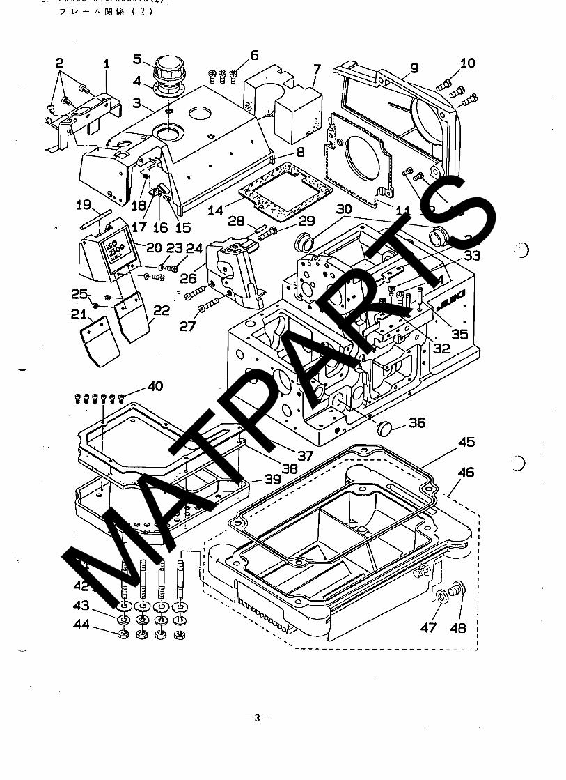
. - - REF. NO. -NOTE PART NO. D E S C R I P T I O N t > + 4 AHT.
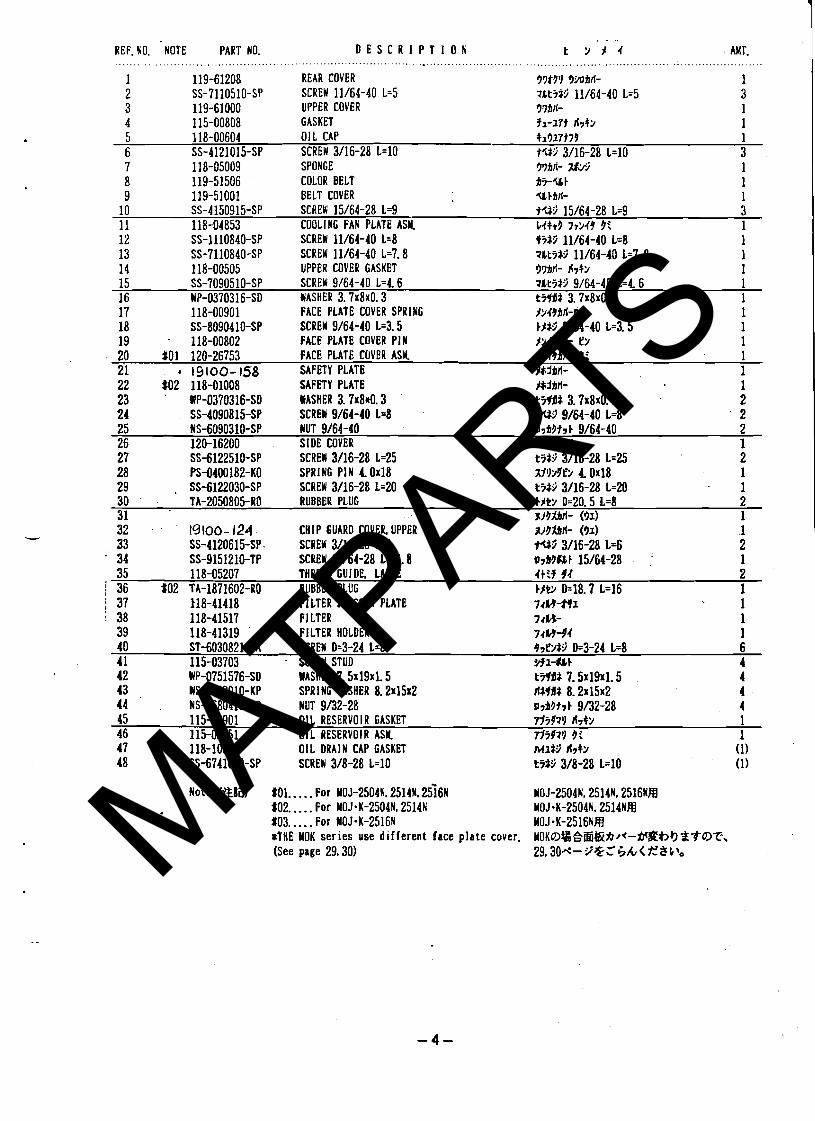
1 119-61208 REAR COVER 37t3'1 3MBlf- 1 2 SS-7110510-SP SCREW 11/64-40 1-5 t k t i i 3 11/64-40 L=5 3 3 119-61000 LIPPER COVER 379IT- 1 4 115-00808 GASKET fa-17t A7+9 1 5 118-00604 OIL CAP +a317t79 1 6 SS-4121015-SP SCREW 3/16-28 L=10 tW 3/16-28 L=10 3 7 118-05009 SPONGE 8 119-51506 COLOR BELT 9 119-51001 BELT COVER Y EBIT- 1
10 SS-4150915-SP SCREW 15/64-28 L=9 tY:j 15/64-28 L=9 3 11 118-04853 COOLING FAN PLATE ASH. C4b9 77949 9 i 1 12 SS-1110840-SP SCREW 11/64-40 L=8 13 SS-1110840-SP SCREW 11/64-40 L=7.8 14 118-00505 UPPER COVER GASKET 15 SS-7090510-SP SCREW 9/64-40 1 ~ 4 . 6 7ht i t3 9/64-40 L=4 6 1 16 UP-0370316-SO WASHER 3 . 7 ~ 8 ~ 0 . 3 t%a 3.7x8x0.3 1 17 118-00901 FACE PLATE COVER SPRING 18 SS-8090410-SP SCREW 9/64-40 L=3.5 19 118-00802 FACE PLATE COVER PIN 20 $01 120-26753 FACE PLATE COVER ASY l9499lf- 3: 1 21 4 19100-158 SAFETY PLATE l&jbrl- 1 22 $02 118-01008 SAFETY PLATE 23 ' WP-0370316-SO WASHER 3 .7~84 .3 24 SS-4090815-SP SCREW 9/64-40 L=8 25 NS-6090310-SP NUT 9/64-40 ~7Q3t7t 9/64-40 2 26 120-16200 SIDE COVER Y9#> $If- 1
SS-6122510-SP SCREW 3/16-28 L=25 PS-0400182-KO SPRING PIN 40x18 SS-6122030-SP SCREW 3/16-28 L=20
30 TA-2050805-RO RUBBER PLUG t l b D=20.5 L=8 2 31 313fifi- (31) 1 32 . t9100-124 CHIP GUARD COVER UPPER 33 SS-4120615-SP. SCREW 3/16-28 14 34 SS-9151210-TP SCREW 15/64-28 1~11.8 35 11 8-05207 THREAD GUIDE. LARGE 4ttf 9.1 2
j 36 $02 TA-1871602-R0 RUBBER PLUG tlb D=18.7 L=16 1 i 37 118-41418 Fl LTER PRESSER PLATE 7rH-HI 1 1 38 118-41517 F l LTER 7r lJ- 1
39 118-41319 FILTER HOLDER 74L94.1 1 40 ST-6030821-OA SCREW D=3-24 L=8 47Cf i i D=3-24 L=8 6 4 1 115-03703 . SCREW STUD HI-U t 4
UP-0751576-SD MASHER 7.5~19~1.5 uS-0822010-KP SPRING WASHER 8 . 2 ~ 1 5 ~ 2 NS-6680410-SP NUT 9/32-28
45 115-03901 OIL RESERVOIR GASKET TJiJ71) fi7+9 1 46 115-03851 011 RESERVOIR ASY rli971) 3: 1 47 118-10306 OIL DRAIN CAP GASKET 48 SS-6741010-SP SCREW 3/8-28 L=10
Note (&8W $01.. . . . For MOJ-2504N. 25141.266~ MOJ-2504N. 2514N. 2516NH $02.. . . . For MOJ-K-2504N, 2514N M0J.K-2504N. 2514NR $03.. . . . For M0J.K-2516N MOJ-K-2516NM STHE MOK series use d i f ferent face p la te cover. M O K ~ l ~ ~ & h ~ * - ~ $ h ? ) ~ T O T , (See page 29.30) 29,304-Y%C,'h< f8bt0 MATPARTS
MATPARTS
. .. REF. NO. -NOTE PART NO. D E S C R I P T I O N t > ) . I MT.
. . . . . . . . . . . . . . . . . . . . . . . . . . . . . . . . . . . . . . . . . . . . . . . . , . . . . . . . . . . . . . . . . . . . . . . . . . . . . . . . .
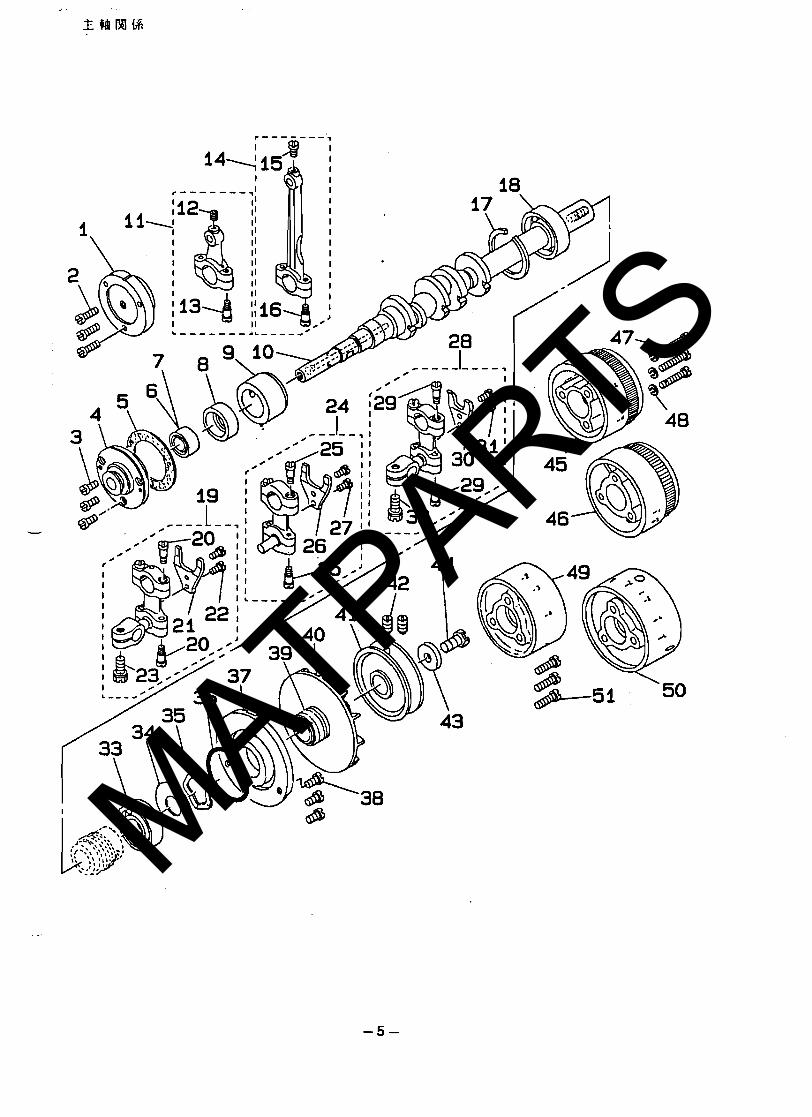
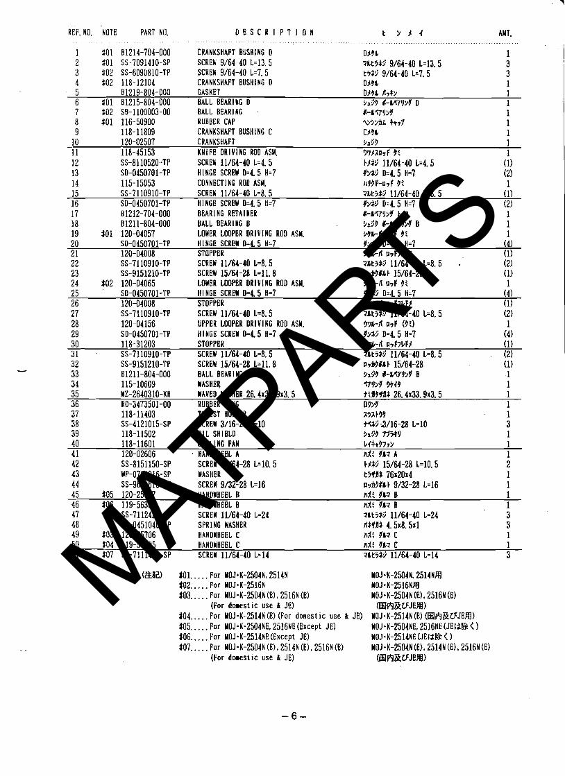
1 $01 91214-704-000 CRANKSHAFT BUSH1 NG 0 D14b 1 2 $01 SS-7091410-SP SCREW 9/64-40 1~13 .5 7Ltit.3 9/64-40 L=13.5 3 3 $02 SS-6090810-TP SCREW 9/64-40 1 ~ 7 . 5 ti*> 9/64-40 L=7.5 3 4 $02 118-12104 CRANKSHAFT BUSHING D DNL 1 5 91219-804-000 GASKET D m fiy+> 1 6 $01 B1215-804-000 BALL BEARING D 9193 $-&<7'1>4 D 1 7 #02 SB-1100003-00 BALL BEARING . I-LQll>'l 1 8 $01 116-50900 RUBBER CAP T/LAL +t7Y 1 9 118-11809 CRANKSHAFT BUSHING C C19L 1
10 120-02507 CRANKSHAFT Yi93 1 11 118-45153 KNIFE DRlVl NG ROD ASM. 3 7 2 ~ 1 ~ ~ 3: 1 12 SS-8110520-TP SCREW 11/64-40 L=4.5 13 SO-0450701-TP H I NGE SCREW D=45 H=7 14 115-15053 CONNECTING ROD ASM. 15 SS-7110910-TP SCREW 11/64-40 1 ~ 8 . 5 ?ltit:j 11/64-40 L=8.5 (1) 16 SO-0450701-TP HI NGE SCREW D=45 H=7 99r:i D=4 5 H=7 (2) 17 81212-704-000 BEARING RETAl NER I-M7ll>Y Ej7 1 18 01211-804-000 BALL BEARING B 9193 I-b?7J?Y B 1 19 $01 120-04057 LOWER LOOPER DRIVING ROD ASM. 99kL-n DYF 3 i 1 20 SD-0450701-TP HINGE SCREW D=45 H=7 9233 D=4 5 H=7 (4) 2 1 120-04008 STOPPER 99b-fi D~F~LFZ . (1) 22 SS-7110910-TP SCREW 11/64-40 1 ~ 8 . 5 ?&t5$9 11/64-40 L=8.5 . (2) 23 SS-9151210-TP SCREW 15/64-28 L=l l . 8 07fi3$1b 15/64-28 (1) 24 $02 120-04065 LOWER LOOPER DRlVl NG ROD ASM. 991,-L-n n7F 9: 1 25 S O - O ~ ~ O ~ O I - T P HINGE SCREW D=4 5 H=7 9>fP D=4 5 H=7 (4) 26 120-04008 STOPPER 99h-fi DYF~CFI (1) 27 SS-7110910-TP SCREW 11/64-40 1 4 . 5 28 120-04156 UPPER LOOPER DRlVl NG ROD ASW. 29 SD-0450701-TP HINGE SCREW D=4 5 H=7 30 118-31203 STOPPER 3 7 ~ - f i D & J L F $ (1) 3 1 SS-7110910-TP SCREW 11/64-40 1 4 . 5 ?&kit.> 11/64-40 L=8.5 (2) 32 SS-9151210-TP SCREU 15/64-28 1~11 .8 ~7fi!J$bE 15/64-28 (1) 33 B1211-804-000 BALL BEARING B 9x53 Ir-&gll>Y B 1 34 115-10609 WASHER ?79>%' W49 1 35 WZ-2640310-KH WAVED WASHER 26.4~33.9~3.5 t t l l4Jdf 26.4~33.9~3.5 1 36 RO-3473501-00 RUBBER R I N G OYYY 1 37 118-11403 THRUST HOLDER aiaE39 1 38 SS-4121015-SP SCREW 3/16-28 L=10 r(f3 3/16-28 L=10 3 39 118-11502 011 SHIELD 9x99 flsll 1 40 118-11601 COOL1 NG FAN ~ 4 + + 3 7 0 1 4 1 120-02606 HANDWHEEL A n;X: %'M A 1 42 SS-8151150-SP SCREW 15/64-28 1~10 .5 43 WP-0764016-SP WASHER 44 SS-9681610-'TP SCREW 9/32-28 L=16 45 $05 120-25607 HANDWHEEL B ni : YI? B 1 46 $06 119-56307 HANDWHEEL B ~ 2 : 4&? B 1 47 SS-7112420-SP SCREW 11/64-40 L=24 48 WS-0451040-KP SPRl NG WASHER 49 403 120-25706 HANDWHEEL C 50 $04 119-56505 HANDWHEEL C ni: YL? C 1 51 $07 SS-7111410-SP SCREW 11/64-40 L=14 ?&tit.> 11/64-40 L=14 3
Note (&ai!) $01.. . . . For Y0J.K-2504N, 2514N $02.. . . . For MOJ-K-2516N $03.. . . . For MOJ-K-2504N (El, 2516N (El
(For donestic use & JE) #04.. . . . For MOJ-K-2514N (E) (For domestic use & JE) 405.. . . . For MOJ-K-2504NE. 2516NE(Except .lE) $06.. . . . For M0J.K-2514NE (Except JE) $07.. . . . For M0J.K-2504N (El, 2514N (E), 2516N (El
(For doeest~c use & JE)
MATPARTS
MATPARTS
MATPARTS
MATPARTS
MATPARTS
MATPARTS
MATPARTS
MATPARTS
MATPARTS
MATPARTS
MATPARTS
MATPARTS
MATPARTS
MATPARTS
MATPARTS
MATPARTS
MATPARTS
MATPARTS
MATPARTS
MATPARTS
MATPARTS
MATPARTS
MATPARTS
MATPARTS
MATPARTS
MATPARTS
MATPARTS
MATPARTS
MATPARTS
MATPARTS
MATPARTS
MATPARTS
MATPARTS
MATPARTS
MATPARTS
MATPARTS
MATPARTS
MATPARTS