Embed Size (px)
Citation preview

1
Media, Connections, and Collisions
Honolulu Community College
Cisco Academy Training Center
Semester 1
Version 2.1.1

2
Overview Network foundation is the physical layer, Layer 1
of the OSI Reference Model. Physical layer defines the electrical, mechanical,
procedural, and functional specifications for activating, maintaining, and deactivating the physical link between end systems.
Different types of networking media. How network devices, cable specifications,
network topologies, collisions and collision domains affect how much data can travel across the network and how fast.

3
Speed and throughput: 10-100 Mbps Average $ per node: Moderately Expensive Media and connector size: Medium to Large Maximum cable length: 100m (short)

4
Shielded Twisted Pair - STP Combines the techniques of shielding,
cancellation, and twisting of wires. STP gives greater protection from all types of
external interference, but is more expensive than UTP (unshielded twisted-pair cable).
Shielding must be properly grounded. If improperly grounded, shielding to act like an
antenna (noise pickup).

5
Speed and throughput: 10-100 Mbps Average $ per node: Least Expensive Media and connector size: Small Maximum cable length: 100m (short)

6
UTP - Unshielded Twisted Pair Least expensive networking media, and most
common. Small size (.43 cm diameter) easy to install, and more cables in wiring ducts.
Relies on cancellation to minimize interference. prone to electrical noise and interference
To reduce crosstalk, the number of twists in the wire pairs varies.
Uses solid RJ-45 connection. Fastest copper media. Disadvantage is short unboosted runs - 100m.

7
Coaxial Cable (coax) Longer unboosted distances than other copper
media. Two sizes:
Thinnet -10Base2 - 185m.
Thicknet -10Base5 - 500m.
Speed and throughput: 10-100 Mbps Average $ per node: Inexpensive Media and connector size: Medium Maximum cable length: 500m (medium)

8
Problems with Coax Difficult to work with - thicker diameter. Requires proper grounding at both ends. Improper grounding can give more
interference.

9
Fiber Optic Cable
Speed and throughput: 100+ Mbps Average $ per node: Most Expensive Media and connector size: Small Maximum cable length: Up to 2km Single mode: One stream of laser-generated light Multimode: Multiple streams of LED-generated light

10
Fiber Optic Cable Uses modulated light transmissions. Most expensive networking media, in materials
and installation. Not susceptible to EMI and RFI. Does not conduct electricity (advantage for use
between buildings, floors, etc). Fastest speeds of all networking media. Long unboosted distances - up to 2 km. Used primarily for backbone cabling.

11
Wireless Communications Wireless signals are electromagnetic waves,
which can travel through a vacuum or air. no physical medium is necessary.
12
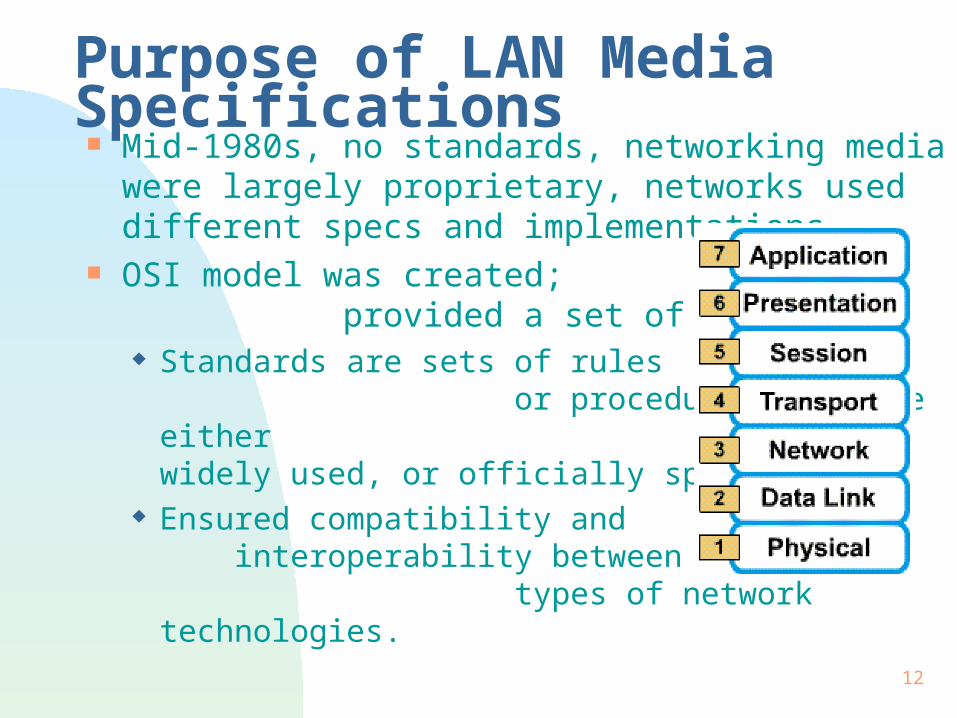
Purpose of LAN Media Specifications Mid-1980s, no standards, networking media were
largely proprietary, networks used different specs and implementations.
OSI model was created; provided a set of standards. Standards are sets of rules or
procedures that are either widely used, or officially specified.
Ensured compatibility and interoperability between various types of network technologies.

13
Standards Many groups joined the movement to specify the
types of cable that could be used for specific purposes or functions. IEEE - Institute of Electrical and Electronics
Engineers UL - Underwriters Laboratories EIA - Electrical Industries Association TIA - Telecommunications Industry Association

14
Standards (cont.) IEEE
cabling requirements in 802.3 (Ethernet) and 802.5 (Token Ring) specifications.
UL identification program that lists markings for
shielded and unshielded twisted-pair media. TIA/EIA
568-A cabling standards, 569 wiring closets. greatest impact on networking media standards.

15

16
TIA/EIA 568-A Focuses on standards for horizontal cabling.
horizontal cabling includes the networking media that extends from wiring closet to workstation.
Maximum distance for cable runs in horizontal cabling is 90 m (CAT 5 UTP ).
Patch cords or cross-connect jumpers located at the horizontal cross-connect cannot exceed 6 m.
Patch cords to connect equipment at the work area - 3m.

17
UTP - Category Ratings Cat 1 - not rated for data. Cat 2 - for voice/PBX (private branch exchange).
Low performance UTP, for voice, low speed data. Cat 3 - use for 10BaseT networks. Cat 4 - low loss, 10baseT, up to 16 Mbps. Cat 5 - low-loss extended frequency, for
100baseX systems - Fast Ethernet.

18
Ethernet 10BaseT Layer 1 Components and Devices
Passive (no energy to operate) components: patch panels, plugs, cabling, jacks.
Active devices: transceivers, repeaters, hubs.
Connectors & Jacks: RJ-45 8 wire connector, terminates UTP. Jacks require punch-down tool.
Cabling: standard is Cat 5 UTP.

19
Ethernet Layer 1 Components Patch panel: convenient groupings of RJ-45
jacks. 8 wire jacks, require punch-down tool.
Transceiver: a combination of transmitter and receiver. Connects to AUI port to give a particular type of
connection. Transmit from one pin configuration and/or media
to another.

20
Ethernet Layer 1 Components (2) Repeaters: regenerate, and retime
signals, which enables cables to reach longer distances. cannot filter network traffic.
Hubs: multiport repeaters. serve as the center of a
star topology. Layer 1 components create or act on the bits.
They recognize no information patterns in the bits, no addresses, and no data.
Their function is simply to move bits around.

21

22
Types of Networks Shared media - occurs when multiple hosts
have access to the same medium. Ethernet is a shared media environment.
Point-to-point - one device is connected to only one other device via a link.

23
Circuit vs Packet Switched Circuit-switched - indirectly-connected network
in which actual electrical connection is ‘switched on’ for the duration of the communication. Telephone service is circuit-switched. ISDN.
Packet-switched - link connection between two communicating hosts, where the source sends messages in packets. Advantage: many hosts can share same link. Frame Relay is an example of packet-switched.

24
Collisions & Collision Domains Ethernet allows only one data packet to access
the media at any one time. If two or more nodes transmits at the same time, a
collision occurs, and the data is damaged. Collision domain - area in the network, where the
data packets originate and collide. When a collision occurs, the data packets that
collide are destroyed, bit by bit. CSMA/CD is the method Ethernet uses to handle
media contention. Developed at the University of Hawaii in 1960s.
25
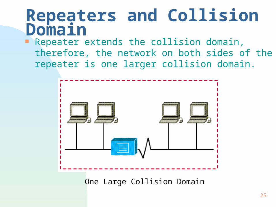
Repeaters and Collision Domain Repeater extends the collision domain, therefore,
the network on both sides of the repeater is one larger collision domain.
One Large Collision Domain
26
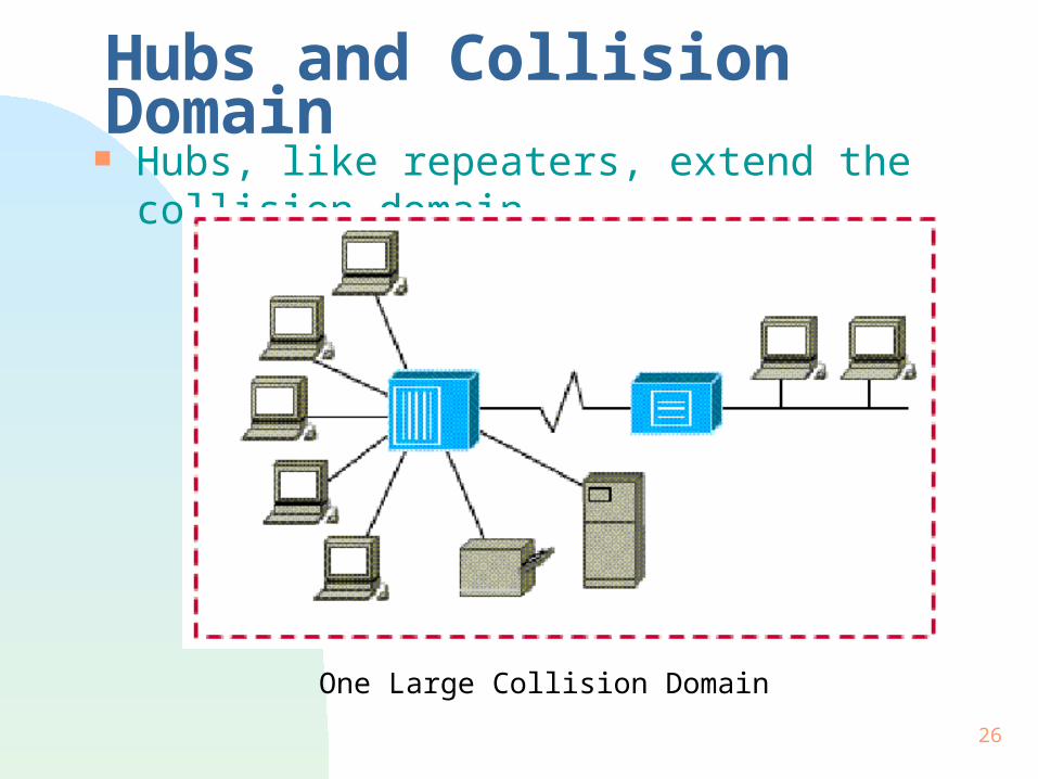
Hubs and Collision Domain Hubs, like repeaters, extend the collision domain.
One Large Collision Domain

27
5-4-3-2-1 Rule of Thumb Five sections of the network, Four repeaters or hubs, Three sections of the network have hosts, Two sections are link segments (for link purposes), One large collision domain.
One Collision Domain

28
Segmentation Purpose is to reduce size of collision domains. Can segment with bridges, switches or routers.
One Collision Domain One Collision Domain

29
Physical Topology Topology defines the structure of the network. Physical topology is the actual layout of the wire
(media).

30
Logical Topology Logical topology is how information flows through
a network. A network’s physical topology may be completely
different from its logical topology. Ethernet 10Base-T uses an extended-star physical
topology, but acts like a logical bus topology. Token Ring uses a physical star, and a logical ring. FDDI uses a physical and a logical ring.

31
Linear Bus Topology Bus topology has all nodes
connected directly to one link. Physical perspective:
all hosts are connected to each other, and can communicate directly.
a break in the cable disconnects hosts from each other.
Logical perspective: enables all devices to see all signals from all other
devices.

32
Ring Topology Ring topology has each node
connected directly to only the two adjacent nodes.
Physical perspective: all devices are directly connected to two adjacent
devices in a daisy-chain. Logical perspective:
each station passes the data to its adjacent station.
33
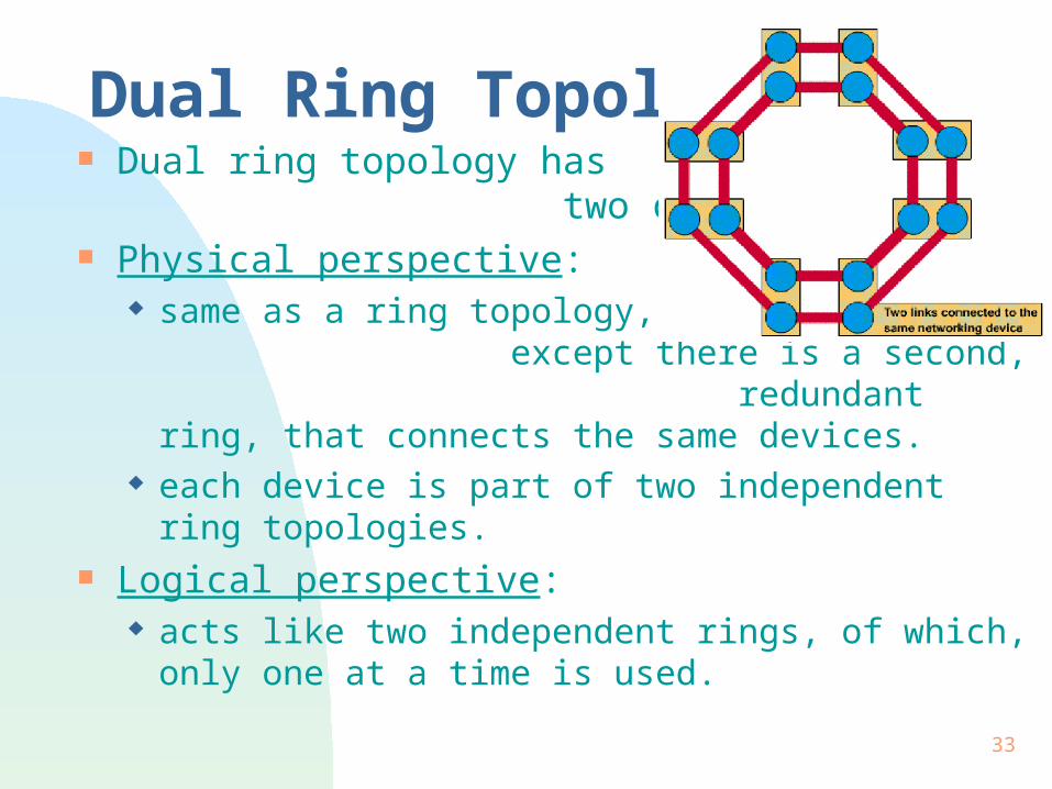
Dual Ring Topology Dual ring topology has
two concentric rings. Physical perspective:
same as a ring topology, except there is a second, redundant ring, that connects the same devices.
each device is part of two independent ring topologies.
Logical perspective: acts like two independent rings, of which, only one
at a time is used.

34
Star Topology Star topology has a central
node with all links to other nodes radiating from it.
Physical perspective: all nodes communicate with each other, through
central node. central node is a single point of failure.
Logical perspective: all information goes through one device. desirable for security or restricted access reasons. but network is susceptible to any problems in the
star's central node.

35
Extended Star Topology Each node that links to center
node is also the center of another star.
Physical perspective: a core star topology, with each of the end nodes
acting as the center of its own star topology. advantage is shorter wiring runs. limits number of devices that interconnect to any
one central node. Logical perspective:
extended star topology is very hierarchical.
36
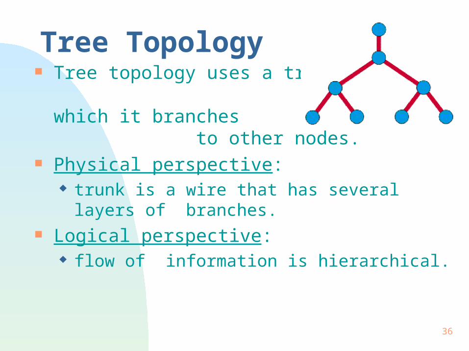
Tree Topology Tree topology uses a trunk
node from which it branches to other nodes.
Physical perspective: trunk is a wire that has several layers of branches.
Logical perspective: flow of information is hierarchical.

37
Irregular Topology Irregular network topology
has no obvious pattern to the links and nodes.
Physical perspective: wiring is inconsistent; the nodes have varying
numbers of wires leading from them. Logical perspective:
no obvious pattern.

38
Mesh Topology In a mesh topology every
node is linked directly to every other node.
Physical perspective: every node is physically connected to every other
node, creating a redundant connection. requires large amount of media and connections.
Logical perspective: behavior of a mesh topology depends greatly on
the devices used.

39
Cellular Topology Cellular topology consists of
circular or hexagonal areas, each of which has an individual node at its center.
Physical perspective: a geographic area that’s divided into regions (cells)
for the purposes of wireless technology. Logical perspective:
communication is directly between nodes or only with adjacent cells (distance limitations and interference affect operations).

40
Summary Function of the physical layer is to transmit data. Networking media:
Coax, STP, UTP, fiber. TIA/EIA-568-A & TIA/EIA-569 - most widely used
standards for networking media. Collisions and collision domains. Physical topology vs logical topology.


![[PPT]ALOHA FROM HAWAII - WordPress.com · Web view* HONOLULU - HARBOUR HONOLULU - AIRPORT HONOLULU IOLANI PALACE - HONOLULU ROYAL GUARD KAMEHAMEHA THE GREAT LAIE MORMON TEMPLE HONOLULU](https://img.pdfslide.us/doc/110x75/5af655b67f8b9a5b1e8effdc/pptaloha-from-hawaii-view-honolulu-harbour-honolulu-airport-honolulu-iolani.jpg)


![[PPT]ALOHA FROM HAWAIIekladata.com/T87xXLe0Y72JoKgvTgg575PI2tM/Hawaiil.pps · Web view* HONOLULU - HARBOUR HONOLULU - AIRPORT HONOLULU IOLANI PALACE - HONOLULU ROYAL GUARD KAMEHAMEHA](https://img.pdfslide.us/doc/110x75/5af655b67f8b9a5b1e8effcd/pptaloha-from-view-honolulu-harbour-honolulu-airport-honolulu-iolani-palace.jpg)