Embed Size (px)
Citation preview

1
Introduction
1.1 Anatomy of a Vehicle, Vehicle Functionality and Components
Customers today perceive the value of an automobile based on its structure, its mobil-ity function, its appearance, and other miscellaneous options such as infotainment. This fact motivates the automotive engineers to develop engineering metrics to judge each of these perspectives in a quantitative manner to help them improve their design, benchmark their vehicles against their competitors and, more importantly, meet the legal regulations. For example, the performance of a vehicle structure is dependent on the following criteria: Crash - worthiness (or passive safety), service life (or dura-bility), its noise, vibration and harshness (NVH) characteristics, in addition to new metrics that have recently been viewed as value - adding, such as structure recyclabil-ity and weight effi ciency.
Crash - worthiness defi nes the vehicle structure ability or capacity to absorb dynamic energy without harming its occupants in an accident, while the durability is the prob-ability that the structure will function without failure over a specifi ed period of time or frequency of usage. The NVH describes the structure performance in absorbing the different vibration levels and providing a desired (designed) level of comfort. The noise is defi ned as vibration levels with low frequency ( < 25 Hz), while harshness is the term for vibrations at ( ∼ 25 – 100 Hz). All the above structural requirements are controlled by intrinsic (density, Young ’ s modulus) and extrinsic (thickness, geometry, and shapes) material properties and joining strategies. So the material, its shape selections, and the manufacturing process control the overall performance of vehicu-lar structures.
The vehicle mobility function is controlled by its ride and handling dynamics in addition to the drive - line and power - train systems ’ reliability. Again, the choice of material (weight and stiffness) and the design geometries (center of gravity location) affect the vehicle ’ s performance. The vehicle appearance can be described in its styling, which is controlled by the panels ’ shape, its geometrical fi t (gaps, fl ush
The Automotive Body Manufacturing Systems and Processes, First Edition. Mohammed A. Omar.© 2011 John Wiley & Sons, Ltd. Published 2011 by John Wiley & Sons, Ltd.
COPYRIG
HTED M
ATERIAL

2 The Automotive Body Manufacturing Systems and Processes
setting, etc.), and its fi nal paint fi nish. Human visual perception evaluates the vehi-cle ’ s fi nish in terms of specifi c visual qualities: Color properties, encompassing three color attributes, in addition to color matching between the different vehicle parts such as the steel body and the plastic trim. Also, surfaces ’ spatial properties as well as the vehicle ’ s geometric attributes such as gloss, texture, and haze control the customer ’ s perception. For example, if the paint on a vehicle suffers from orange peel, i.e. the paint looks like the peel of an orange, the customer might mistakenly observe this as a defect (variation) in the sheet metal roughness.
The vehicle ’ s main components and sub - systems can be categorically listed as: Power - train, chassis, exterior and interior trims, and the body in white (BiW) or vehicle body - shell. The power - train is composed of the prime - mover (the internal combustion engine, or electric motor), the gear system, and the propulsion and drive shafts, while the chassis includes the suspension and steering components, in addition to the wheel, tires, and axles. The interior and exterior trims compose the front and rear ends, the door system, and the cockpit trim. Finally, the body in white is made up of the closures (doors, hood, tail - gate) and the frame, see Figure 1.1 ). The frame can be of a uni - body design (Figure 1.2 (a) uni - body), a body - on - frame (Figure 1.2 (b)), or a space - frame (Figure 1.2 (c)). The uni - body design features stamped panels, while the space - frame is made up of extrusions and cast parts. The BiW closures are selected based on the vehicle ’ s constituent material dent - resistance properties (i.e. yield strength) while the frame is designed to provide specifi c torsional and bending stiffness.
1.2 Vehicle Manufacturing: An Overview
After reading Section 1.1 , we can conclude that vehicle performance is judged based on design strength, stiffness, energy absorption, dent resistance, and surface rough-ness. However, before designers select a material or design a specifi c shape, they should consider manufacturability. The manufacturability from an automotive body structure ’ s point of view is described in terms of the design formability, the joining
Figure 1.1 Left: the vehicle body structure without closures, right: the complete vehicle BiW

Introduction 3
ability (weldability and hemming ability), the achieved surface fi nish and surface energy, and its overall cost. This fact motivates a deeper understanding of the auto-motive manufacturing processes and systems, because it will ultimately decide the design ’ s overall cost, fi nal shape, and functionality, that is, the design validity.
The automotive manufacturing activities can be analyzed on two levels: the manu-facturing system and process levels. The manufacturing system view is typically investigated from three different perspectives: the production line (the structural aspect ) which covers the machinery, the material handling equipment, the labor resources, and its allocations to the different activities. The transformational aspect includes the functional part of the manufacturing system that is the conversion of the raw materials into fi nished or semi - fi nished products. The transformational activities include all the stamping, casting, welding, machining and painting efforts within the plant. The third aspect is the procedural aspect which describes the operating pro-cedures and strategies, which is further viewed from two different levels; the strategic level which identifi es the product type, and volume (product planning), given the operating environment conditions (customer demands and regulatory issues). Additionally, the strategic plan includes the resources ’ allocation in the manufactur-ing enterprise. The second level is the operational level which is focused on produc-tion control, i.e. meeting the strategic plan objectives through planning, implementing, and control and monitoring activities. These operational activities are further catego-rized by [1] :
Figure 1.2 Top left: (a) a uni - body design, top, right: (b) truck platform; and bottom right: (c) space - frame design

4 The Automotive Body Manufacturing Systems and Processes
1. aggregate production planning which suggests product plans based on the required product volume, using a generic unit such as the vehicle platform not type, to increase the level of confi dence from the forecast information;
2. production process planning which controls the production techniques to be used, in addition to process routes and sequence;
3. production scheduling to determine an implementation plan for the time schedule for every job in the process route;
4. production implementation which is the execution of the actual production plan according to the time schedule and allocated resources;
5. production control to measure and reduce any deviations from the actual plan and time schedules.
Another important view on the automotive manufacturing systems relates to the information, materials, and value - added (cost) fl ows within the plant. The raw materi-als and supplier parts fl ow from upstream to downstream through the material supply system, the material handling system and fi nally through the material distribution system. However, the information fl ows in the opposite direction, that is from down-stream to upstream, to synchronize the rhythm of production and control its quality; this information fl ow is typically called the pull production system to indicate that the customer side controls the quantity and quality (product type) of the production. On the other hand, the old push system meant that the manufacturing plant outputs vehicles according to a mass production scheme without any feedback from the customer side.
The automobile manufacturing processes are divided into two plants: the assembly plants and the power - train plants. Both of these plants specialize in different transfor-mational processes and convert different raw materials into fi nal parts. However, both are synchronized in time to integrate their fi nal outputs into complete vehicles.
1.2.1 Basics of the Assembly Processes
An automotive assembly plant is responsible for the fabrication of the complete vehicle BiW, starting from a steel and/or aluminum coil and ending with a complete painted car shell. Additionally, the power - train, chassis components, interior and exterior trims are all integrated into the BiW at the end of the assembly process in the fi nal assembly area.
The assembly sequence starts with the receiving area for the coil (which is typi-cally made out of steel and aluminum), which also includes a testing laboratory to check material thickness and surface characteristics. After passing the testing, the coil is either stored or staged for blanking. The blanks are then transferred to the stamping press lines to form the different vehicular panels. A typical BiW consists of about 300 – 400 stamped pieces, however, only a few main panels affect the overall

Introduction 5
geometry, fi t and fi nish. These panels are the roof, the trunk (inner, outer, and pan), the hood (inner and outer), the under - body, the wheel - house, the body - side, A and B pillars, the fl oor pan, the front module (engine cradle, crush zones, shock towers), the quarter panels, and doors (inner, outer). Some of these panels are displayed in Figure 1.3 .
After the stamping process, some of the panels are joined to create sub - systems in specialized cells, as in the case for the doors where their inners and outers are adhesively bonded, hemmed and spot - welded. Additional cells exist in the stamping area for other components which are then fed to the body - weld or body - shop area. The stamping process utilizes mechanical and hydraulic presses with different tonnage, accessories and dies, so it can handle different panels ranging in shape and size, from 0.1 – 6.5 mm in thickness and with dimensions as small as 1 x panel thick-ness to as large as 500 x panel thickness.
In the body - shop area, the different panels are joined to form the car shell, starting with the under - body and then the body - side (left - and right - hand) outers. The joining of such panels is fi rst done using tack welding to hold the pieces in place, followed by permanent spot welds. A typical vehicle shell has around 5000 spot welds, achieved through robotic welders working in designated cells and programmed offl ine. The completed body shells will also go through a dimensional check process using laser illumination with a charged coupled devices (CCD) camera system to monitor the shell gaps, fl ush setting and fi t. The body - weld also features metal inert gas (MIG) welding for the under - body.
The robotic welding cells are controlled and monitored through separate program-mable logic controllers (PLCs) which are then connected through a main controller to enable the complete line control through a master PLC.
Figure 1.3 The different panels of the vehicle structure

6 The Automotive Body Manufacturing Systems and Processes
The completed BiW is then transferred to the paint - line. The paint booth area cleans the car shells in immersion tanks and applies a conversion coating layer (iron phosphate or zinc phosphate) followed by an electro - coat or e - coat layer. The sub-sequent paint layers require drying or curing, through a combination of convection and radiation - based ovens. Spray paint booths follow the immersion stages, to apply the primer, top coat and clear coat layers. Also the paint booth area features other important steps such as applying the under - body wax and sealants followed by their curing process. Inspection for paint quality in terms of thickness, color match and contaminants is also important in the paint - line. In the paint - line, the vehicles might be taken out of the overall production sequence to create color batches, thus reducing the paint color change time. However, at the end of the line, all vehicles are arranged back in sequence.
After the paint - line, vehicles are transferred to the fi nal assembly area, where the interior (cockpit, seats, etc.) and exterior trims are installed. The fi nal assembly area consists mainly of manual labor using power - tools and fi xtures for the ergonomics, in addition to autonomous carriers that transfer the power - train components (engine, transmission, etc.) for assembly work (installing the cables, fuel hoses, and control-lers) and then to the marriage area. The marriage area is where the power - train is installed in the vehicle body. The fi nal assembly area features a variety of mechanical fastening and riveting operations to install the different trim components in the vehicle shell. Additionally, a variety of sensory systems is used to check the dimen-sional fi t of the different components, in addition to ensuring the proper torque for each joint.
The fi nal step in the assembly process tests the vehicle operation and build, using a chassis dynamometer and a water - test chamber.
The assembly plants require a sophisticated control system that not only monitors the different areas ’ performance (stamping, body - weld, paint and fi nal assembly) but also synchronizes these activities with the reception of parts from the suppliers ’ network and with the power - train facility.
The fl ow of parts and semi - fi nished vehicles within an assembly plant go through different layouts within each assembly area. In the stamping area, the parts are dis-tributed between the different stamping presses depending on the press tonnage and the dies assigned to that press. Also the staging and storing of stamped pieces are done on racks and then transferred to the body - shop or to specialized cells separately, see Figure 1.4 . In other words, the layout in the stamping area is similar to a product - based layout not a process - based one. A product - based layout is similar to the ones found in small workshops or a carpenter shop, where the fl ow of pieces (panels) and equipment allocation (dies) changes according to the product type (vehicle type).
In the body - weld, there is a main assembly line where the sub - assemblies are fed to be joined to the main body frame. So the body - shop layout is a process - based layout, because the focus is on repeating the same process for all product (vehicle) types. The body - weld overall layout is similar to a spine, where the specialized cells that create the door sub - assemblies (joining inner and outer), the hood, the under -

Introduction 7
body, feed the main line that joins them to the body main shell, see Figure 1.5 . The paint - line layout starts with a single straight line for the cleaning and the conditioning steps, the conversion coating (phosphate), and the e - coating immersion tanks. Then the vehicles are sent to a selectivity bank area (with a fl exible conveyor system) so batches of vehicles of the same color are created for the spray booths. Some original equipment manufacturers (OEMs) like Toyota do not use the color - batching strategy but instead developed their paint - line booths to use a cartridge color system, where the robots can switch between different cartridges to change colors, thus eliminating the need to clean the paint supply line every time the color is changed. The overall fl ow within the paint - line is displayed in Figure 1.6 , illustrating the different painting steps and layout. The fi nal assembly area follows a process - based layout using a straight or a horseshoe - shaped assembly line.
1.2.2 Basics of the Power - train Processes
The power - train facilities are mainly responsible for building the vehicle power - train and drive - line components such as the engine and transmission. The power - train
Figure 1.4 A schematic of a typical stamping line layout

8 The Automotive Body Manufacturing Systems and Processes
plants feature different transformational manufacturing processes from those found in the assembly plants. The power - train plants use a variety of forging, casting and machining operations to fabricate the engine components and the transmission. For example, the engine cylinder blocks are made of cast iron or are cast out of aluminum or in some cases from aluminum with a magnesium core to reduce the total weight of the engine. After the entire engine and the transmission components have been manufactured, they are assembled manually. For example, after casting and machin-ing the engine cylinder block and the exhaust manifold, forging the pistons and the crankshaft, and fi nishing the valves, the crankshaft is installed manually in the cyl-inder block and secured by the bearing caps, which are torqued automatically. Then the pistons are lubricated and installed in the cylinder block carefully to prevent scratching the cylinder lining. Then the cylinder head is mounted and torqued to hold
Figure 1.5 The layout of a body - weld line
Side outer right
Side outer left
Engine Compartment
Rear Floor a
ssembly
Floor asse
mbly
Roof Cowl
Figure 1.6 The basic processes in an automotive paint - line
Introduction 9
the valves assembly. The inlet and exhaust manifolds are installed next and fastened mechanically. The testing of the engine operation is done next, using an engine dynamometer.
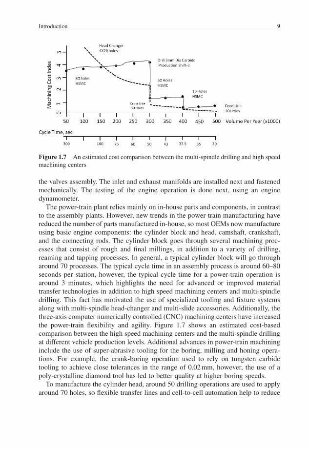
The power - train plant relies mainly on in - house parts and components, in contrast to the assembly plants. However, new trends in the power - train manufacturing have reduced the number of parts manufactured in - house, so most OEMs now manufacture using basic engine components: the cylinder block and head, camshaft, crankshaft, and the connecting rods. The cylinder block goes through several machining proc-esses that consist of rough and fi nal millings, in addition to a variety of drilling, reaming and tapping processes. In general, a typical cylinder block will go through around 70 processes. The typical cycle time in an assembly process is around 60 – 80 seconds per station, however, the typical cycle time for a power - train operation is around 3 minutes, which highlights the need for advanced or improved material transfer technologies in addition to high speed machining centers and multi - spindle drilling. This fact has motivated the use of specialized tooling and fi xture systems along with multi - spindle head - changer and multi - slide accessories. Additionally, the three - axis computer numerically controlled (CNC) machining centers have increased the power - train fl exibility and agility. Figure 1.7 shows an estimated cost - based comparison between the high speed machining centers and the multi - spindle drilling at different vehicle production levels. Additional advances in power - train machining include the use of super - abrasive tooling for the boring, milling and honing opera-tions. For example, the crank - boring operation used to rely on tungsten carbide tooling to achieve close tolerances in the range of 0.02 mm, however, the use of a poly - crystalline diamond tool has led to better quality at higher boring speeds.
To manufacture the cylinder head, around 50 drilling operations are used to apply around 70 holes, so fl exible transfer lines and cell - to - cell automation help to reduce
Figure 1.7 An estimated cost comparison between the multi - spindle drilling and high speed machining centers

10 The Automotive Body Manufacturing Systems and Processes
the cycle time. Other specialized operations like the cam boring include the use of a long - line boring bar with custom fi xture, to lower or raise the cam. On the other hand, to manufacture the crankshaft, the OEMs have to apply a series of different operations with tight tolerances, that include balancing the mass of the forged steel material, turning of both edges for clamping, and turning for the main and pin bear-ings, drilling the oil holes, fi nish grinding for the main and pin bearings, then super-fi nish the main and pin bearings. Finally, the crankshaft is washed, balanced and inspected. The balancing is done using an intelligent fi xture that rotates the shaft and compensates for any imbalances by drilling holes.
The camshaft follows a similar processing sequence to that of the crankshaft, with changes in the tooling used and with the addition of a hardening process, where the shaft is heated using induction coils, then cooled rapidly.
The power - train manufacturing processes are also responsible for making the transmission components, mainly the gear system. The typical material for the dif-ferent automotive gears is based on alloyed steel that provides the hard fi nish for the gear teeth while the core is soft and tough, so that it resists continuous use in terms of fatigue and wear resistances. These requirements motivate the use of different heat treatment steps to achieve the hard teeth and ductile core, which include a carburizing step to increase the carbon content within a controlled depth within the gear surface, a quenching process to increase the hardness, and a tempering step to improve the core toughness.
The basic operation used to form the gear is based on hot forging, followed by variety of hobbing and shaping cutting steps to generate the gear teeth. In the shaping process, a cutting gear with the designed profi le is used to generate a similar tooth profi le in the blank gear, however, in the hobbing process, a worm - like cutter cuts teeth on a cylindrical blank to generate the teeth, hence the hobbing process cannot be used to generate internal gears. Other subsequent operations include gear shaving,
Figure 1.8 The basic processes within a power - train facility

Introduction 11
where a helical gear - like cutter, with closely spaced grooves, meshes with the gear so that a controlled material is removed from the gear teeth surfaces.
The standard processes within a power - train facility are displayed in Figure 1.8 . So, the overall functional look of the vehicle manufacturing processes can be shown in Figure 1.9 .
1.3 Conclusion
The automotive manufacturing processes (assembly and power - train) play a major role in deciding on the vehicles ’ design characteristics and the overall cost. Thus it is very important for designers and engineers to understand the current manufacturing infrastructure available in their company ’ s production lines. This will pinpoint the manufacturing capabilities and limitations. At the end of the day, the designer will specify the design tolerances but the machine will control the achieved tolerances. Additionally, designers should consider the materials ’ compatibility from the joining process welding point of view, to avoid galvanic corrosion issues.
Additionally, designers should be aware that the vehicle design complexity in terms of number of parts and intricate shapes results in additional manufacturing steps (added cost and processing time). Also, the number of robotic welders and stamping presses should be taken into account due to their direct impact on the pro-duction rate. However, one should recognize that different OEMs make their deci-sions with regard to the vehicle type, volume and design based on their business models, which might be based on one of the following;
1. competing based on differentiation; 2. competing based on cost; or 3. competing based on time to market.
Figure 1.9 The basic processes in an automotive assembly plan

12 The Automotive Body Manufacturing Systems and Processes
A company competing based on different and distinguished vehicle types might add complications to their manufacturing systems to achieve new added features or provide a wide range of options. However, an OEM competing on cost aims to reduce the manufacturing cost through less complicated designs and options. The OEMs who compete based on response time typically utilize common components and designs shared between different vehicle types and between old and new models of the same vehicle type. For example, the engine cradle design can be shared between old and new models without affecting the customer ’ s perception of the vehicle as a new model, at the same time it helps the OEM to cut the development time and cost, in addition to reducing the set - up changes in the manufacturing plants.
Additionally, recent changes in the automotive market have forced the automotive OEMs to increase their product portfolio to accommodate new demands from emerg-ing markets, mainly in Brazil, Russia, India, and China or the BRIC countries. This increase in vehicle models has shifted the OEMs ’ manufacturing models from the economy of scale to an economy of scope , which motivates further understanding of the manufacturing environment because such a shift adds complications in the fol-lowing areas: the sequencing of the different models, the production capacity fore-casting, and parts (suppliers) and sub - systems ’ diversity. So new manufacturing and design strategies should be implemented and explored to alleviate some of these challenges such as the use of modular systems and subsystems between the different models, which reduce the parts ’ diversity and the variations within the processes. At the same time, the modularity might have negative impact on the OEMs ’ overall fl exibility [2] .
The impact of the above challenges on the automotive industry have led the auto-motive OEMs to revise their production and business strategies through mergers with other OEMs and by implementing effi cient manufacturing procedures such as lean manufacturing and its different derivatives and versions created to suit each company style and product type. The number of automotive OEMs has dropped from 36 in 1970, to 21 in 1990, and to 14 in 2000. However, the number of automobiles pro-duced is around 55 million vehicles [3] with the majority of production taking place in Asia (around 18 million vehicles), followed by Western Europe (17 million vehicles) and then the USA (around 11.5 million vehicles).

Exercises
Problem 1
In your own words, describe the current metrics used to judge the automobiles, by a typical customer and by an automotive engineer.
Problem 2
What is the difference between the noise and vibration within the context of the automotive NVH requirement?
Problem 3
Explain the three manufacturing system perspectives.
Problem 4
What is the difference between the operational and strategic operations, within the procedural aspect?
Problem 5
List the basic manufacturing processes involved in the making of the automobile BiW, and comment on each process layout and drivers.
Problem 6
List the main differences between the automotive power - train and assembly proc-esses, from the following perspectives: the dependence on suppliers ’ parts, and the nature of the processes utilized.

14 The Automotive Body Manufacturing Systems and Processes
Problem 7
What is the difference between the gear hobbing and shaping processes?
Problem 8
What is the impact of economy of scale and the economy of scope on the automotive manufacturing process?
Problem 9
Automotive OEMs might compete based on different criteria, what are they?
Problem 10
List three challenges that have impacted the automotive industry in the past decade.