Embed Size (px)
Citation preview
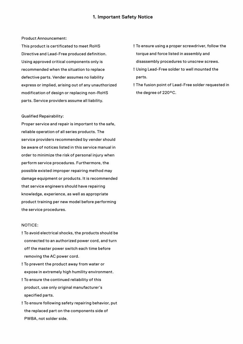
Product Announcement:
This product is certificated to meet RoHS
Directive and Lead-Free produced definition.
Using approved critical components only is
recommended when the situation to replace
defective parts. Vender assumes no liability
express or implied, arising out of any unauthorized
modification of design or replacing non-RoHS
parts. Service providers assume all liability.
Qualified Repairability:
Proper service and repair is important to the safe,
reliable operation of all series products. The
service providers recommended by vender should
be aware of notices listed in this service manual in
order to minimize the risk of personal injury when
perform service procedures. Furthermore, the
possible existed improper repairing method may
damage equipment or products. It is recommended
that service engineers should have repairing
knowledge, experience, as well as appropriate
product training per new model before performing
the service procedures.
NOTICE:
! To avoid electrical shocks, the products should be
connected to an authorized power cord, and turn
off the master power switch each time before
removing the AC power cord.
! To prevent the product away from water or
expose in extremely high humility environment.
! To ensure the continued reliability of this
product, use only original manufacturer’s
specified parts.
! To ensure following safety repairing behavior, put
the replaced part on the components side of
PWBA, not solder side.
! To ensure using a proper screwdriver, follow the
torque and force listed in assembly and
disassembly procedures to unscrew screws.
! Using Lead-Free solder to well mounted the
parts.
! The fusion point of Lead-Free solder requested in
the degree of 220°C.
1. Important Safety Notice
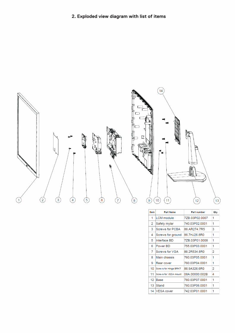
2. Exploded view diagram with list of items
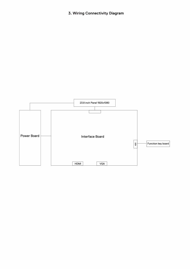
3. Wiring Connectivity Diagram
Power BoardK
B1
Interface Board
VGAHDMI
Function key board
23.8 inch Panel 1920x1080
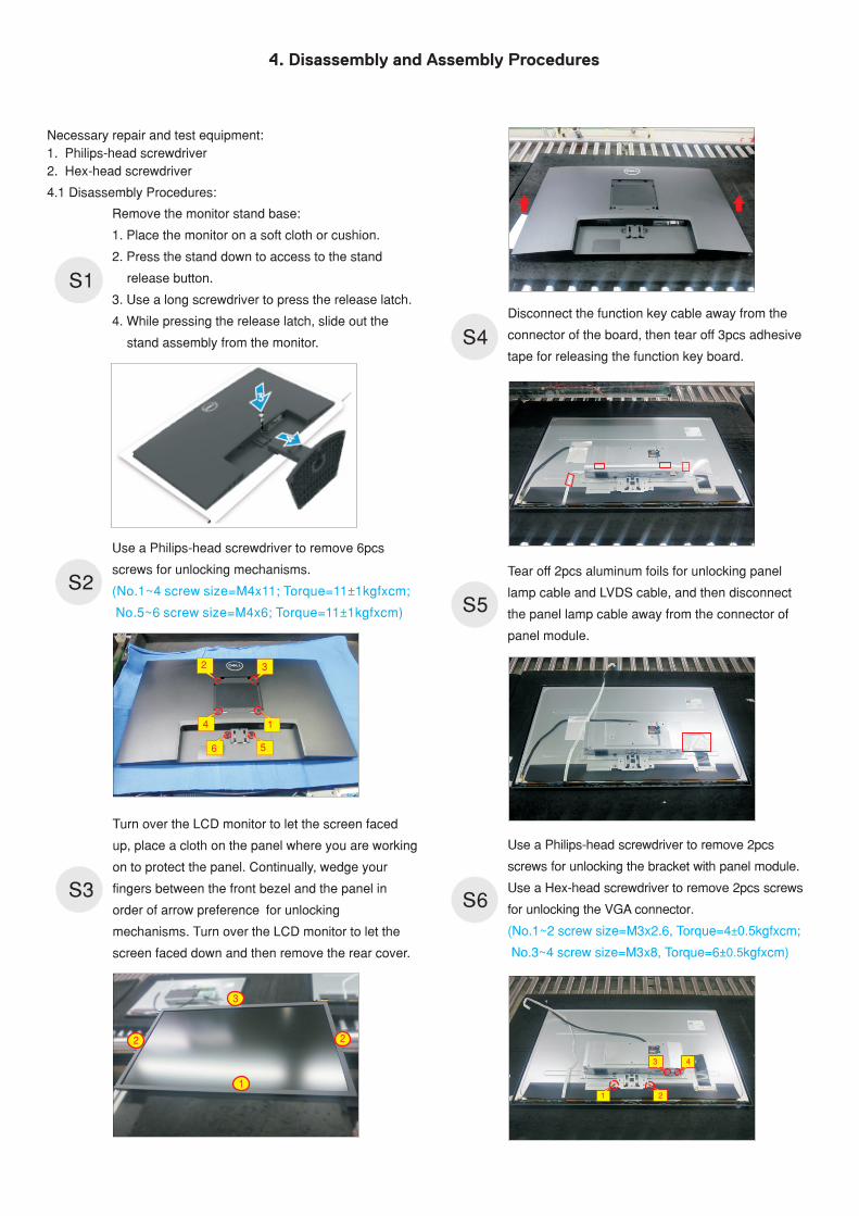
4. Disassembly and Assembly Procedures
4.1 Disassembly Procedures:
Necessary repair and test equipment:
1. Philips-head screwdriver
2. Hex-head screwdriver
S3
S4
S2
S1S1
Remove the monitor stand base:
1. Place the monitor on a soft cloth or cushion.
2. Press the stand down to access to the stand
release button.
3. Use a long screwdriver to press the release latch.
4. While pressing the release latch, slide out the
stand assembly from the monitor.
S5
S6
Turn over the LCD monitor to let the screen faced
up, place a cloth on the panel where you are working
on to protect the panel. Continually, wedge your
fingers between the front bezel and the panel in
order of arrow preference for unlocking
mechanisms. Turn over the LCD monitor to let the
screen faced down and then remove the rear cover.
Use a Philips-head screwdriver to remove 6pcs
screws for unlocking mechanisms.
(No.1~4 screw size=M4x11; Torque=11 1kgfxcm;
No.5~6 screw size=M4x6; Torque=11 1kgfxcm)
±
±
3
1
2 2
2 3
4 1
56
Disconnect the function key cable away from the
connector of the board, then tear off 3pcs adhesive
tape for releasing the function key board.
Use a Philips-head screwdriver to remove 2pcs
screws for unlocking the bracket with panel module.
Use a Hex-head screwdriver to remove 2pcs screws
for unlocking the VGA connector.
(No.1~2 screw size=M3x2.6, Torque=4 0.5kgfxcm;
No.3~4 screw size=M3x8, Torque=6±0.5kgfxcm)
±
Tear off 2pcs aluminum foils for unlocking panel
lamp cable and LVDS cable, and then disconnect
the panel lamp cable away from the connector of
panel module.
2
3 4
1
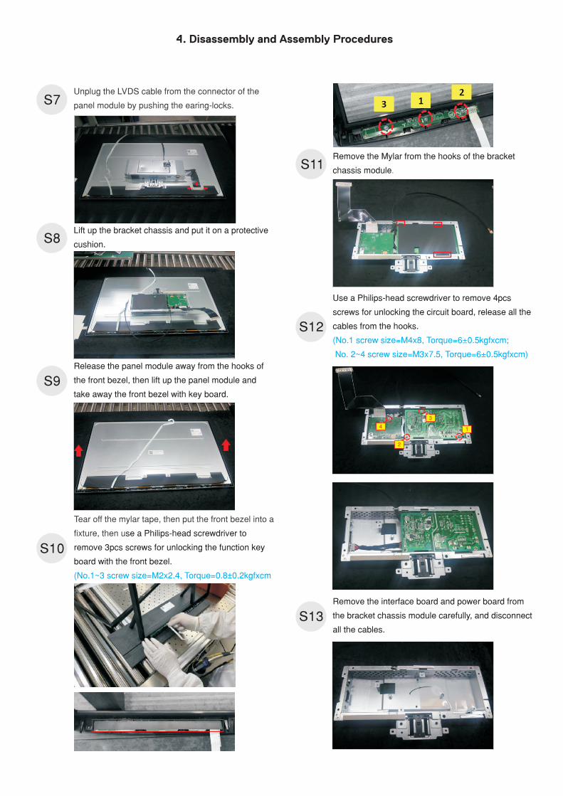
4. Disassembly and Assembly Procedures
S10
S7
S9
S11
S13
S12
Tear off the mylar tape, then ut the front bezel into a
fixture, then u
p
se a Philips-head screwdriver to
remove 3pcs screws for unlocking the function key
board with the front bezel.
(No.1~3 screw size=M2x2.4, Torque=0.8±0.2kgfxcm
S8
Use a Philips-head screwdriver to remove 4pcs
screws for unlocking the circuit board, release all the
cables from the hooks.
(No.1 screw size=M4x8, Torque=6±0.5kgfxcm;
No. 2~4 screw size=M3x7.5, Torque=6±0.5kgfxcm)
Remove the Mylar from the hooks of the bracket
chassis module.
Remove the interface board and power board from
the bracket chassis module carefully, and disconnect
all the cables.
Unplug the LVDS cable from the connector of the
panel module by pushing the earing-locks.
Release the panel module away from the hooks of
the front bezel, then l
.
ift up the panel module and
take away the front bezel with key board
L
.
ift up the bracket chassis and put it on a protective
cushion
3
2
41
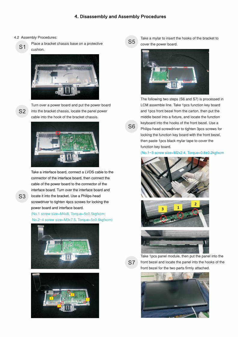
4. Disassembly and Assembly Procedures
Take a mylar to insert the hooks of the bracket to
cover the power board. S5
S6
Take 1pcs panel module, then put the panel into the
front bezel and locate the panel into the hooks of the
front bezel for the two parts firmly attached.
S7
Turn over a power board and put the power board
into the bracket chassis, locate the panel power
cable into the hook of the bracket chassis.
Place a bracket chassis base on a protective
cushion.
4.2 Assembly Procedures:
S2
S1
Take a interface board, connect a LVDS cable to the
connector of the interface board, then connect the
cable of the power board to the connector of the
interface board. Turn over the interface board and
locate it into the bracket. Use a Philips-head
screwdriver to tighten 4pcs screws for locking the
power board and interface board.
(No.1 screw size=M4x8, Torque=5±0.5kgfxcm;
No.2~4 screw size=M3x7.5, Torque=5±0.5kgfxcm)
S3
3
2
41
The following two steps (S6 and S7) is processed in
LCM assemble line. Take 1pcs function key board
and 1pcs front bezel from the carton, then put the
middle bezel into a fixture, and locate the function
keyboard into the hooks of the front bezel Use a
Philips-head screwdriver to tighten 3pcs screws for
locking the function key board with the front bezel,
then paste 1pcs black mylar tape to cover the
function key board.
.
(No.1~3 screw size=M2x2.4, Torque=0.8±0.2kgfxcm
4. Disassembly and Assembly Procedures
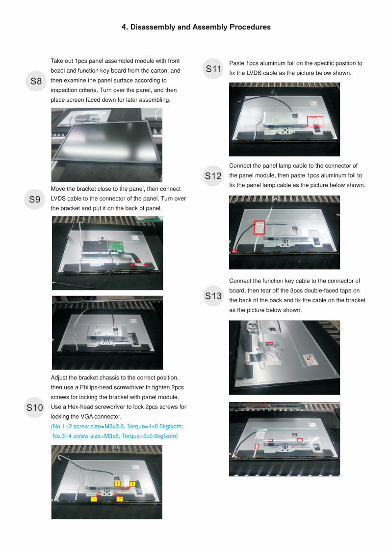
Adjust the bracket chassis to the correct position,
then use a Philips-head screwdriver to tighten 2pcs
screws for locking the bracket with panel module.
Use a Hex-head screwdriver to lock 2pcs screws for
locking the VGA connector.
(No.1~2 screw size=M3x2.6, Torque=4 0.5kgfxcm;
No.3~4 screw size=M3x8, Torque=6±0.5kgfxcm)
±
S13
S10
S12
Connect the function key cable to the connector of
board, then tear off the 3pcs double-faced tape on
the back of the back and fix the cable on the bracket
as the picture below shown.
Take out 1pcs panel assembled module with front
bezel and function key board from the carton, and
then examine the panel surface according to
inspection criteria. Turn over the panel, and then
place screen faced down for later assembling.
S8
Move the bracket close to the panel, then connect
LVDS cable to the connector of the panel. Turn over
the bracket and put it on the back of panel.
S9
2
S11
3 4
1
Paste 1pcs aluminum foil on the specific position to
fix the LVDS cable as the picture below shown.
Connect the panel lamp cable to the connector of
the panel module, then paste 1pcs aluminum foil to
fix the panel lamp cable as the picture below shown.
4. Disassembly and Assembly Procedures
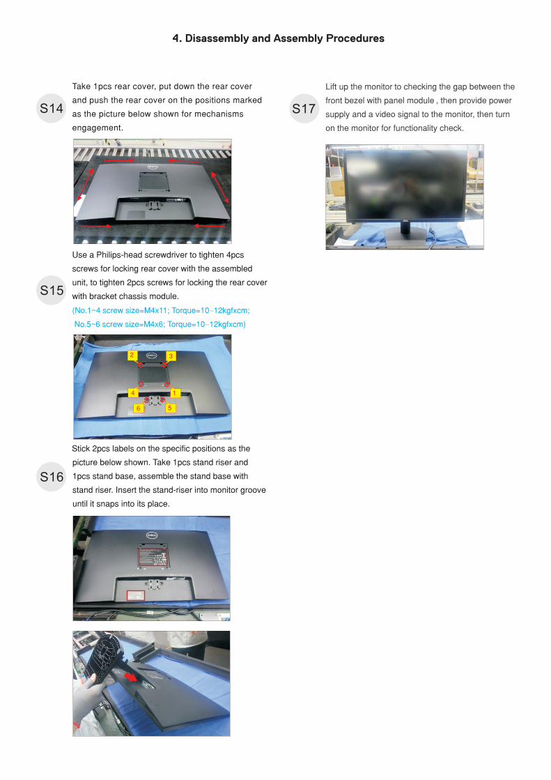
Use a Philips-head screwdriver to tighten 4pcs
screws for locking rear cover with the assembled
unit, to tighten 2pcs screws for locking the rear cover
with bracket chassis module.
(No.1~4 screw size=M4x11; Torque=10 12kgfxcm;
No.5~6 screw size=M4x6; Torque=10 12kgfxcm)
~
~
Take 1pcs rear cover, put down the rear cover
and push the rear cover on the positions marked
as the picture below shown for mechanisms
engagement.
S15
S14
L
front bezel with panel module , then provide power
supply and a video signal to the monitor, then turn
on the monitor for functionality check.
ift up the monitor to checking the gap between the
S17
Stick 2pcs labels on the specific positions as the
picture below shown. Take 1pcs stand riser and
1pcs stand base, assemble the stand base with
stand riser. Insert the stand-riser into monitor groove
until it snaps into its place.
S16
2 3
4 1
56
5. Trouble Shooting Instructions
Self-test
Your monitor provides a self-test feature that allows you to check whether your monitor is functioning properly. If your monitor and computer are properly connected but the monitor screen remains dark, run the monitor self-test by performing the following steps:
1. Turn off both your computer and the monitor.
2. Unplug the video cable from the back of the computer. To ensure proper Self-Test operation, remove all video cables from the back of computer.
3. Turn on the monitor.
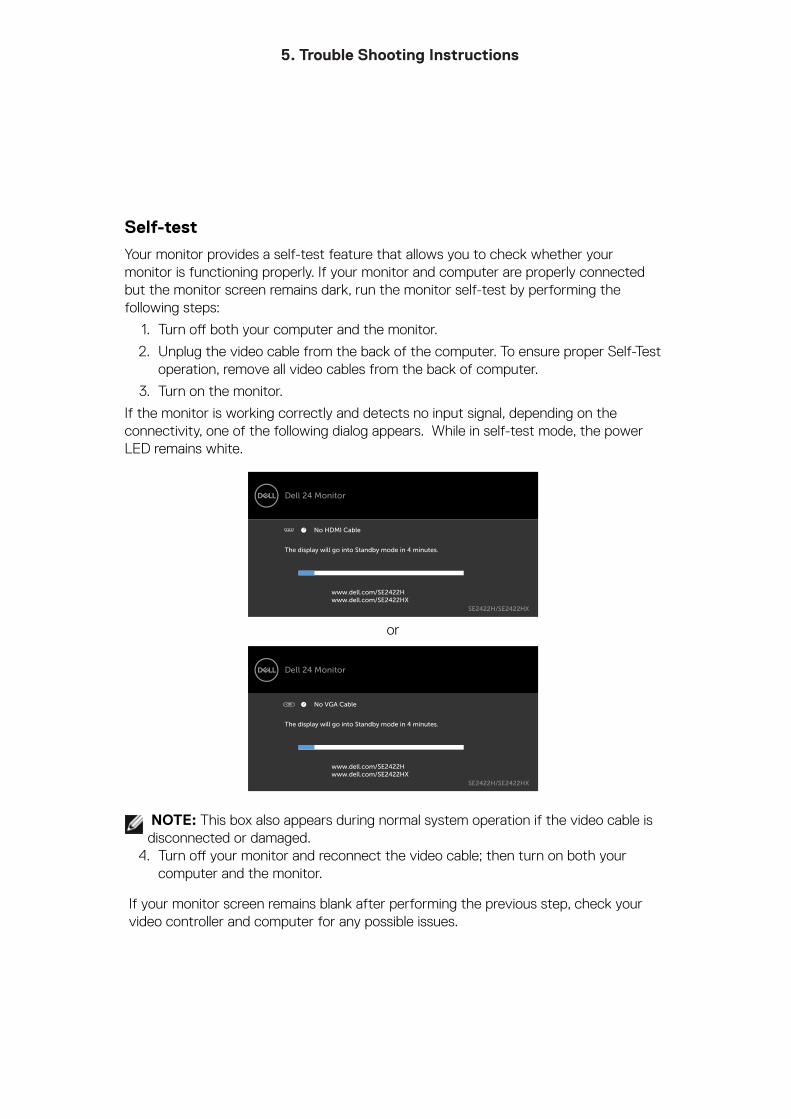
If the monitor is working correctly and detects no input signal, depending on the connectivity, one of the following dialog appears. While in self-test mode, the power LED remains white.
The display will go into Standby mode in 4 minutes.
www.dell.com/SE2422Hwww.dell.com/SE2422HX
Dell 24 Monitor
SE2422H/SE2422HX
No HDMI Cable
or
The display will go into Standby mode in 4 minutes.
www.dell.com/SE2422Hwww.dell.com/SE2422HX
Dell 24 Monitor
SE2422H/SE2422HX
No VGA Cable
NOTE: This box also appears during normal system operation if the video cable is disconnected or damaged.
4. Turn off your monitor and reconnect the video cable; then turn on both your computer and the monitor.
If your monitor screen remains blank after performing the previous step, check your video controller and computer for any possible issues.
5. Trouble Shooting Instructions
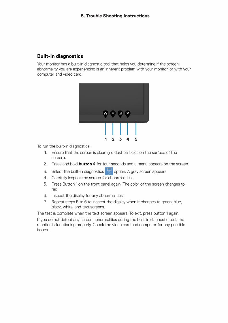
Built-in diagnostics
Your monitor has a built-in diagnostic tool that helps you determine if the screen abnormality you are experiencing is an inherent problem with your monitor, or with your computer and video card.
1 2 3 4 5
To run the built-in diagnostics:
1. Ensure that the screen is clean (no dust particles on the surface of the screen).
2. Press and hold button 4 for four seconds and a menu appears on the screen.
3. Select the built-in diagnostics option. A gray screen appears.
4. Carefully inspect the screen for abnormalities.
5. Press Button 1 on the front panel again. The color of the screen changes to red.
6. Inspect the display for any abnormalities.
7. Repeat steps 5 to 6 to inspect the display when it changes to green, blue, black, white, and text screens.
The test is complete when the text screen appears. To exit, press button 1 again.
If you do not detect any screen abnormalities during the built-in diagnostic tool, the monitor is functioning properly. Check the video card and computer for any possible issues.
5. Trouble Shooting Instructions
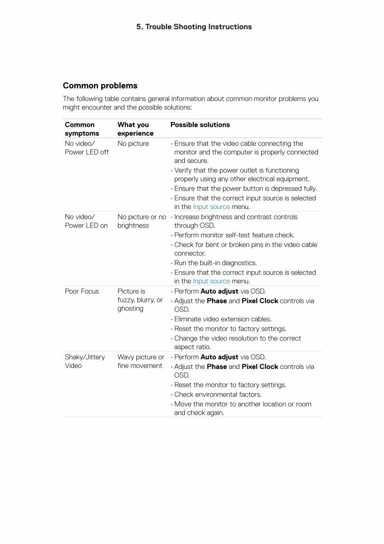
Common problems
The following table contains general information about common monitor problems you might encounter and the possible solutions:
Common symptoms
What you experience
Possible solutions
No video/Power LED off
No picture • Ensure that the video cable connecting the monitor and the computer is properly connected and secure.
• Verify that the power outlet is functioning properly using any other electrical equipment.
• Ensure that the power button is depressed fully.• Ensure that the correct input source is selected
in the Input source menu.
No video/Power LED on
No picture or no brightness
• Increase brightness and contrast controls through OSD.
• Perform monitor self-test feature check.• Check for bent or broken pins in the video cable
connector.• Run the built-in diagnostics.• Ensure that the correct input source is selected
in the Input source menu.
Poor Focus Picture is fuzzy, blurry, or ghosting
• Perform Auto adjust via OSD.• Adjust the Phase and Pixel Clock controls via
OSD.• Eliminate video extension cables.• Reset the monitor to factory settings.• Change the video resolution to the correct
aspect ratio.
Shaky/Jittery Video
Wavy picture or fine movement
• Perform Auto adjust via OSD.• Adjust the Phase and Pixel Clock controls via
OSD.• Reset the monitor to factory settings.• Check environmental factors.• Move the monitor to another location or room
and check again.
5. Trouble Shooting Instructions
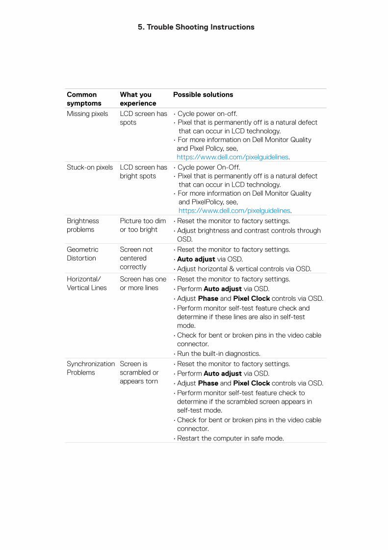
Common symptoms
What you experience
Possible solutions
Missing pixels LCD screen has spots
• Cycle power on-off.• Pixel that is permanently off is a natural defect that can occur in LCD technology.• For more information on Dell Monitor Quality and Pixel Policy, see, https://www.dell.com/pixelguidelines.
Stuck-on pixels LCD screen has bright spots
• Cycle power On-Off.• Pixel that is permanently off is a natural defect that can occur in LCD technology.• For more information on Dell Monitor Quality and PixelPolicy, see, https://www.dell.com/pixelguidelines.
Brightness problems
Picture too dim or too bright
• Reset the monitor to factory settings.• Adjust brightness and contrast controls through
OSD.
Geometric Distortion
Screen not centered correctly
• Reset the monitor to factory settings.• Auto adjust via OSD.• Adjust horizontal & vertical controls via OSD.
Horizontal/Vertical Lines
Screen has one or more lines
• Reset the monitor to factory settings.• Perform Auto adjust via OSD.• Adjust Phase and Pixel Clock controls via OSD.• Perform monitor self-test feature check and
determine if these lines are also in self-test mode.
• Check for bent or broken pins in the video cable connector.
• Run the built-in diagnostics.
Synchronization Problems
Screen is scrambled or appears torn
• Reset the monitor to factory settings.• Perform Auto adjust via OSD.• Adjust Phase and Pixel Clock controls via OSD.• Perform monitor self-test feature check to
determine if the scrambled screen appears in self-test mode.
• Check for bent or broken pins in the video cable connector.
• Restart the computer in safe mode.
5. Trouble Shooting Instructions
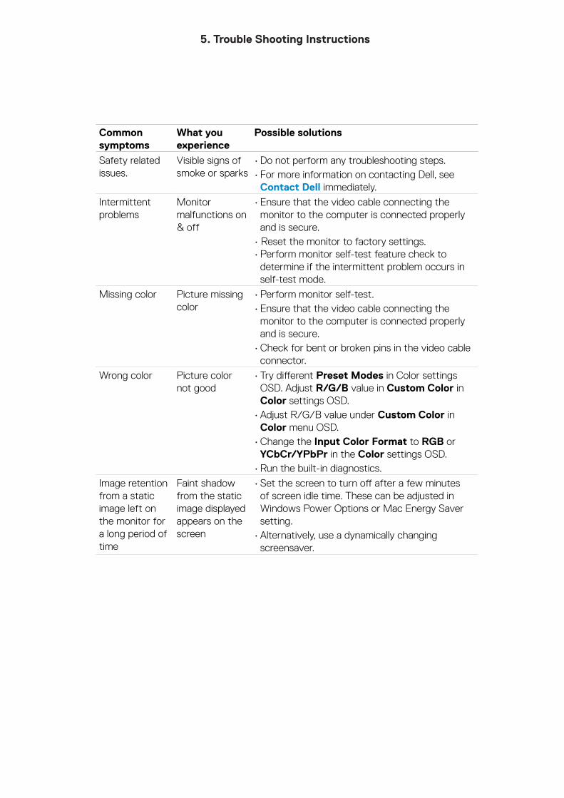
Common symptoms
What you experience
Possible solutions
Safety related issues.
Visible signs of smoke or sparks
• Do not perform any troubleshooting steps.• For more information on contacting Dell, see
Contact Dell immediately.
Intermittent problems
Monitor malfunctions on & off
• Ensure that the video cable connecting the monitor to the computer is connected properly and is secure.
• Reset the monitor to factory settings.• Perform monitor self-test feature check to
determine if the intermittent problem occurs in self-test mode.
Missing color Picture missing color
• Perform monitor self-test.• Ensure that the video cable connecting the
monitor to the computer is connected properly and is secure.
• Check for bent or broken pins in the video cable connector.
Wrong color Picture color not good
• Try different Preset Modes in Color settings OSD. Adjust R/G/B value in Custom Color in Color settings OSD.
• Adjust R/G/B value under Custom Color in Color menu OSD.
• Change the Input Color Format to RGB or YCbCr/YPbPr in the Color settings OSD.
• Run the built-in diagnostics.
Image retention from a static image left on the monitor for a long period of time
Faint shadow from the static image displayed appears on the screen
• Set the screen to turn off after a few minutes of screen idle time. These can be adjusted in Windows Power Options or Mac Energy Saver setting.
• Alternatively, use a dynamically changing screensaver.
5. Trouble Shooting Instructions
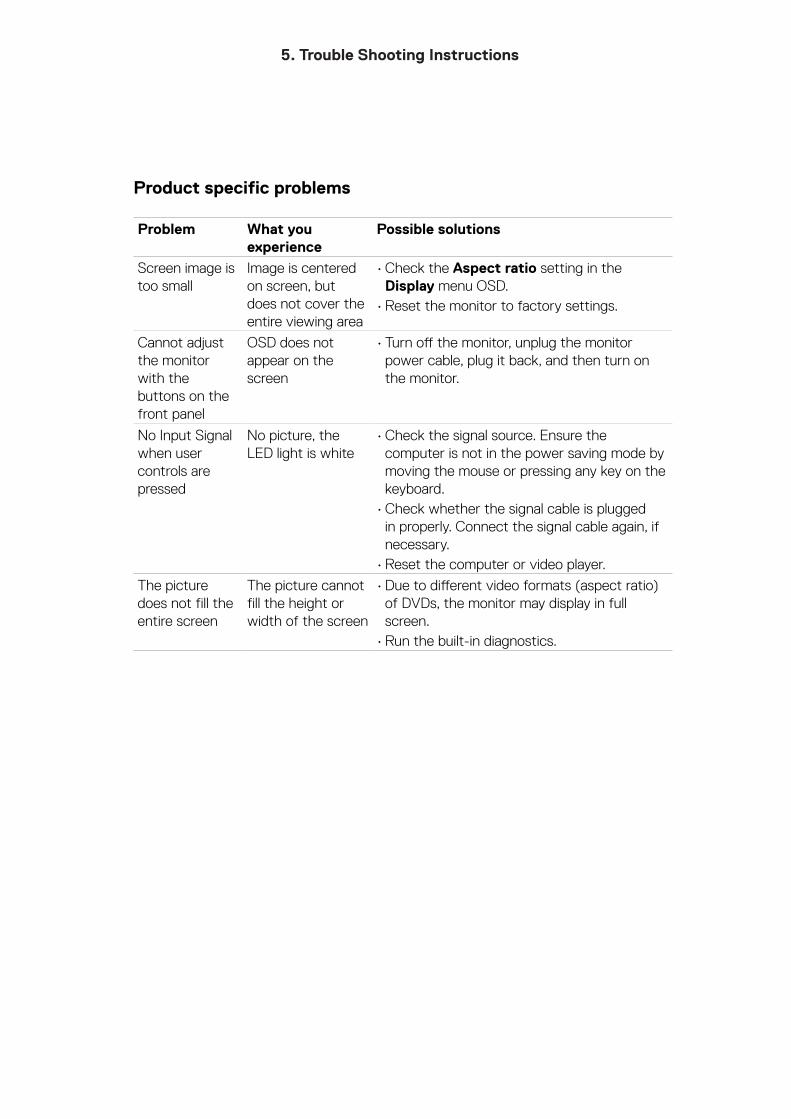
Product specific problems
Problem What you experience
Possible solutions
Screen image is too small
Image is centered on screen, but does not cover the entire viewing area
• Check the Aspect ratio setting in the Display menu OSD.
• Reset the monitor to factory settings.
Cannot adjust the monitor with the buttons on the front panel
OSD does not appear on the screen
• Turn off the monitor, unplug the monitor power cable, plug it back, and then turn on the monitor.
No Input Signal when user controls are pressed
No picture, the LED light is white
• Check the signal source. Ensure the computer is not in the power saving mode by moving the mouse or pressing any key on the keyboard.
• Check whether the signal cable is plugged in properly. Connect the signal cable again, if necessary.
• Reset the computer or video player.
The picture does not fill the entire screen
The picture cannot fill the height or width of the screen
• Due to different video formats (aspect ratio) of DVDs, the monitor may display in full screen.
• Run the built-in diagnostics.