Embed Size (px)
Citation preview
PG - 1/96
NOTICE
The Gradall Company406 Mill Avenue, S.W., New Philadelphia, Ohio 44663
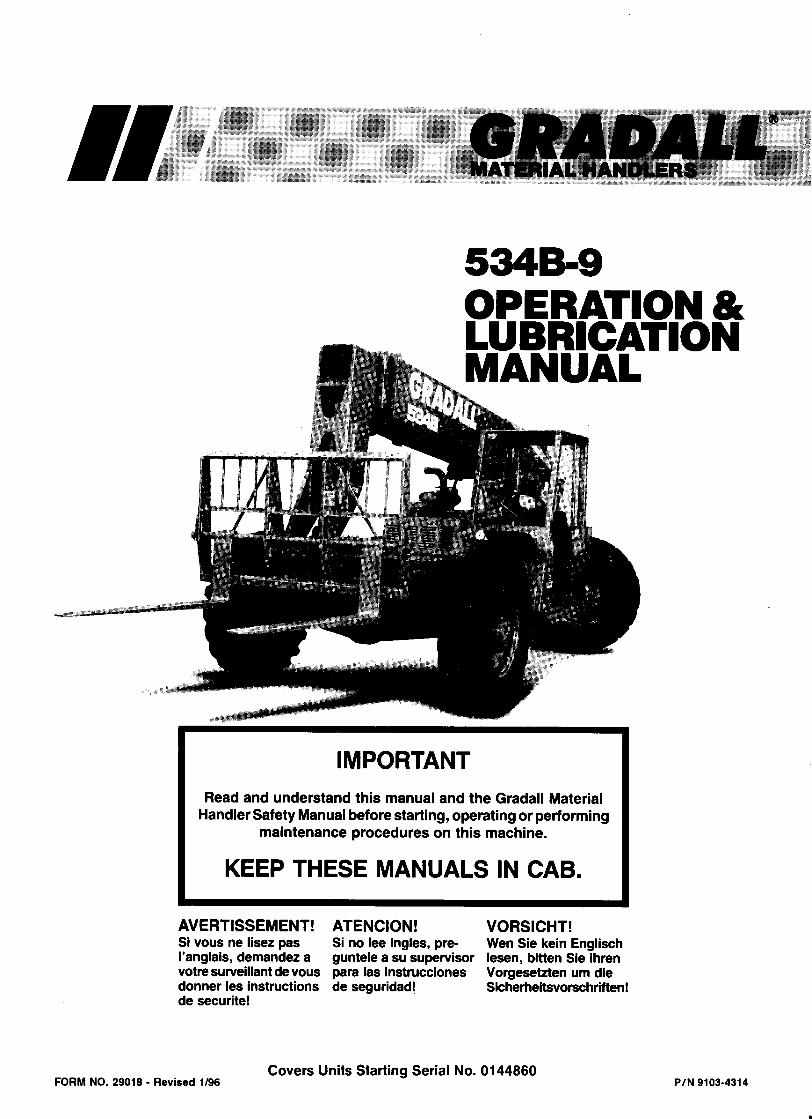
FORM NO. 29018 - Revised 1/96
IMPORTANT SAFETY NOTICESafe operation depends on reliable equipment and proper operatingprocedures. Performing the checks and services described in this manual willhelp to keep your Gradall Material Handler in reliable condition and use ofthe recommended operating procedures can help you avoid accidents.Because some procedures may be new to even the experienced operator werecommend that this manual be read, understood and followed by all whooperate the unit.
Danger, Warning and Caution notes in this manual and the FIEI Rough TerrainForklift Safety Manual will help you avoid injury and damage to the equipment.These notes are not intended to cover all eventualities;it would be impossible toanticipate and evaluate all possible applications and methods of operation forthis equipment.
Any procedure not specifically recommended by The Gradall Company mustbe thoroughly evaluated from the standpoint of safety before it is placed inpractice. If you aren’t sure, contact your Gradall Material HandlerDistributor before operating.
Do not modify this machine without written permission from The GradallCompany.
The Gradall Company retains allproprietary rights to the infor-mat ion contained in th is manual.
The Company also reserves theright to change specifications with-out not ice.
Gradall is a registeremark forhydraulic excavators,hydraulic ma-terial handlers and attachments man-ufactured by The Gradall Company.
General
The manual provides important information tofamiliarize you with safe operating procedures andoperator maintenance requirements for the Gradall/534B-9 Material Handler.
If you have any questions regarding the materialhandler, contact your Gradall Material HandlerDistributor.
Operator Qualifications
Operators of the material handler must be in goodphysical and mental condition, have normal reflexesand reaction time,good vision and depth perceptionand normal hearing. He/she* must not be usingmedication which could impair his abilities nor beunder the influence of alcohol or any other drugduring the work shift.
The operator should also possess a valid, applicabledriver ’s license and must have completed a course oftraining in the safe operation of this type of materialhandling equipment.
In addition, the operator must read, understand andcomply with instructions contained in the followingmaterial furnished with the material handler:
This Operator’s ManualFIEI Rough Terrain Forklift Safety ManualGradall Material Handler Safety ManualAll instruction decals and platesAny optional equipment instructions furnished
The operator must also read, understand andcomply with all applicable Employer, Industry andGovernmental rules, standards and regulations.
Regardless of previous experience operating similarequipment, the operator must be given sufficientopportunity to practice with the 534B-9 MaterialHandler in a safe, open area(not hazardous to peopleor property) to develop the skills and “ feel” requiredfor safe, efficient operation.
Though no offense or discrimination is intended,only the masculine pronouns will be usedthroughout the remainder of this manual.
Orientation
When used to describe location of components inthe material handler, the directions front, rear,right and left relate to the orientation of a personsitting in the operator’s seat.
INTRODUCTION
Related Manuals & Decals
Separate publications are furnished with thematerial handler to provide informationconcerning safety, replacement parts, maintenanceprocedures, theory of operation and vendorcomponents. Replacement manuals, decals andinstruction plates can be ordered from your GradallMaterial Handler Distributor.
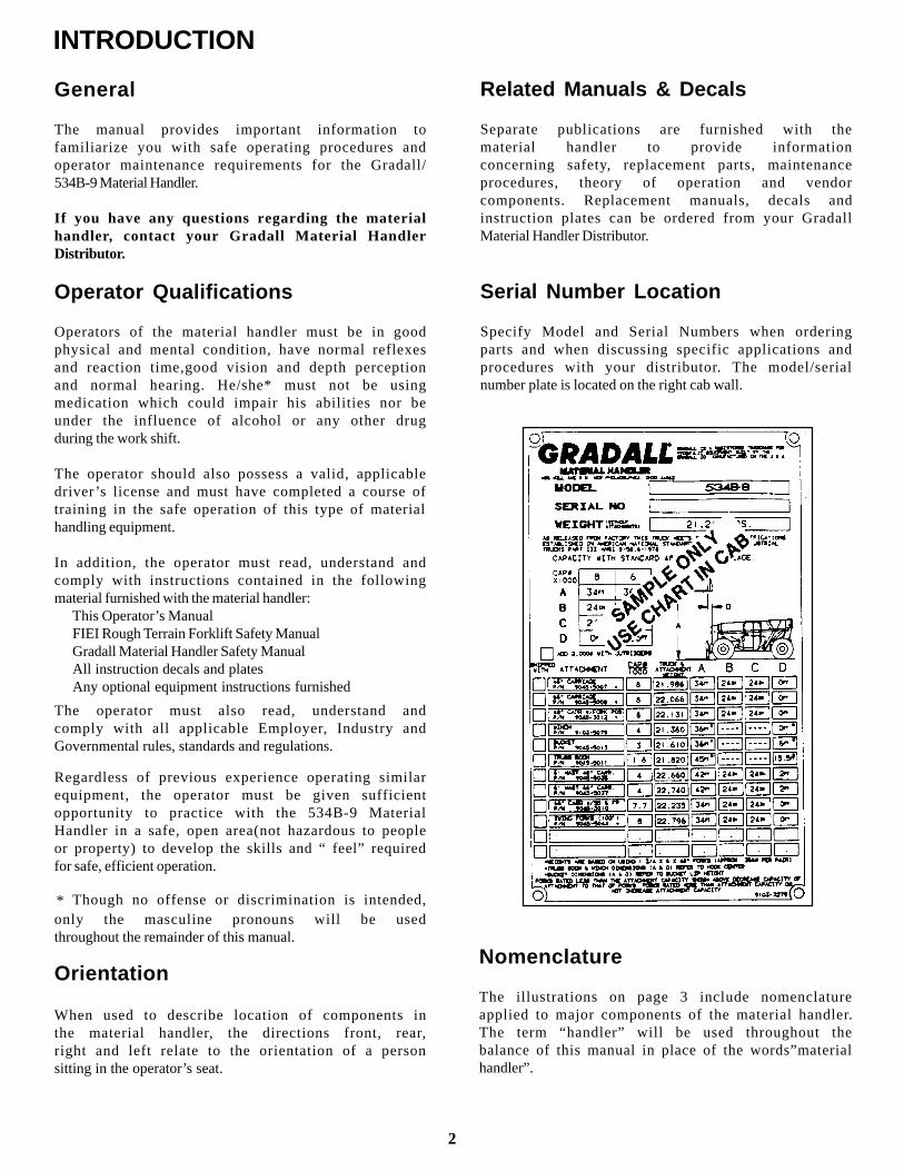
Serial Number Location
Specify Model and Serial Numbers when orderingparts and when discussing specific applications andprocedures with your distributor. The model/serialnumber plate is located on the right cab wall.
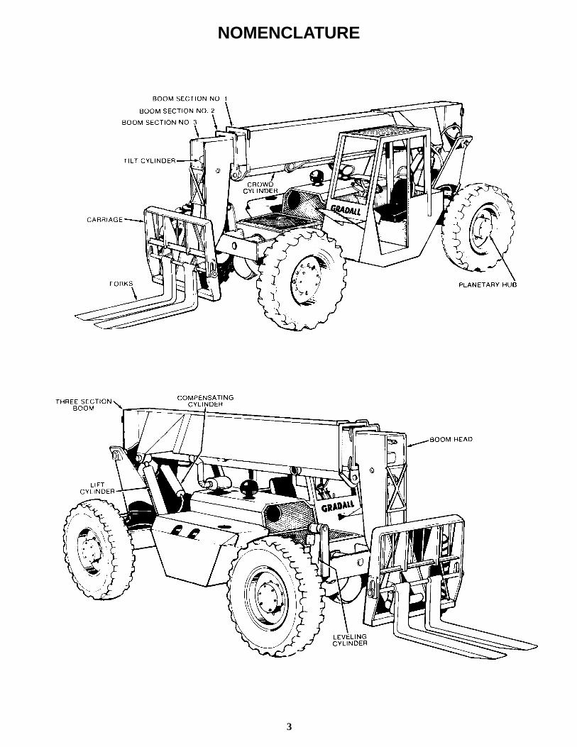
Nomenclature
The illustrations on page 3 include nomenclatureapplied to major components of the material handler.The term “handler” will be used throughout thebalance of this manual in place of the words”materialhandler”.
2
*
3
NOMENCLATURE

SAFETY HIGHLIGHTS
Read and understand this manual, the Gradall Ma-terial Handler Safety Manual and all instructionaldecals and plates before starting, operating or per-forming maintenance procedures on this equipment.
Most safety notes included in this manual involvecharacteristics of the Model 534B-9 MaterialHandler. Refer to the FIEI Rough Terrain ForkliftSafety Manual and the Gradall Material HandlerSafety Manual for safety precautions relating togeneral material handling procedures and practices.
Operators of this equipment must have successfullycompleted a training program in the safe operationo f th i s t ype o f mate r ia l hand l ing equ ipment .
Regardless of previous experience operating similarequipment, the operator must be given sufficientopportunity to practice with the 534B-9 MaterialHandler in a safe open area(not hazardous to peopleor property)to develop the skills and”feel”requiredf o r s a f e , e f f i c i e n t o p e r a t i o n .
Watch for these symbols; they are usedto call your attention to safety notices.
This symbol indicates an extreme hazard whichwould result in high probability of death orserious injury if proper precautions are nottaken.
This symbol indicates a hazard which couldresult in death or serious injury if properprecautions are not taken.
This symbol indicates a hazard which couldresult in injury or damage to equipment orproperty if proper precautions are not taken.
4
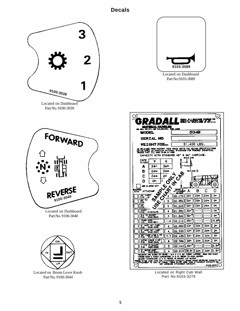
Located on DashboardPart No. 9100-3039
9100-3039
Decals
9103-3089
Located on DashboardPart No.9103-3089
9100-3040
Located on DashboardPart No. 9100-3040
Located on Boom Lever Knob Part No. 9100-3044
Located on Right Cab WallPart No.9103-3279
5
Decals (cont.)
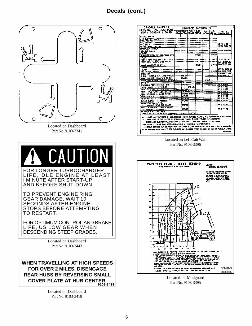
Located on DashboardPart No. 9103-3341
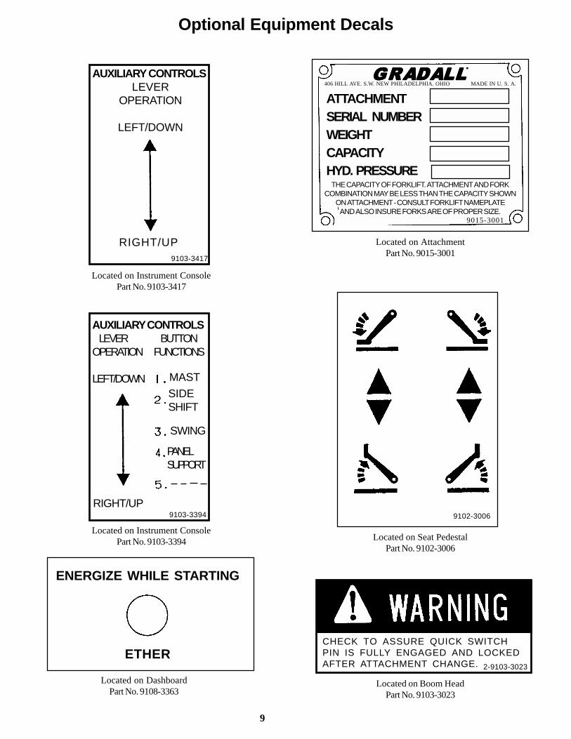
FOR LONGER TURBOCHARGERL I F E , I D L E E N G I N E AT L E A S TI MINUTE AFTER START-UPAND BEFORE SHUT-DOWN.
TO PREVENT ENGINE RINGGEAR DAMAGE, WAIT 10SECONDS AFTER ENGINESTOPS BEFORE ATTEMPTINGTO RESTART.
FOR OPTIMUM CONTROL AND BRAKELIFE, US LOW GEAR WHENDESCENDING STEEP GRADES.
Located on DashboardPart No. 9103-3443
WHEN TRAVELLING AT HIGH SPEEDSFOR OVER 2 MILES, DISENGAGE
REAR HUBS BY REVERSING SMALLCOVER PLATE AT HUB CENTER.
9103-3418
Located on DashboardPart No. 9103-3418
Located on Left Cab WallPart No. 9103-3396
534B-99103-3395
Located on MudguardPart No. 9103-3395
6

Decals (cont.)
IMPORTANTTo prevent damage to the electrical system whenusing booster battery or charger, always connect
(+) POSITIVE TO POSITIVE ( -) NEGATIVE TO NEGATIVE
Located on Battery CoverPart No. 7702-3007
HOT EXHAUSTLocated on Engine Cover
Part No. 7734-3018
DEATH OR INJURY MAY RESULT FROMCONTACTING ELECTRICAL LINES.
UNLAWFULTO PLACE ANY PART OF THISMACHINE OR LOAD WITHIN 10FEET OF HIGH VOLTAGE LINESOF UP TO 50,000 VOLTS.
Located on MudguardPart No. 8360-1011
PARK BRAKEP U L L T O S E T
PUSH TO RELEASE
Located on Seat PedestalPart No. 9104-3129
PARK BRAKE
OFF ON
DO NOT ENGAGE PARKBRAKE WHILE MACHINE IS IN
MOTION - STATIC BRAKE ONLY
Located on Dashboard (Recent units)Part No. 9108-3269
7
HYDRAULIC OIL7702-3006
Located on Hydraulic ReservoirPart No. 7702-3006
Located on BoomPart No. 9100-3031
Located on Right Cab WallPart No.9106-3047
FUEL - DIESELEXTINGUISH ALL OPEN FLAMEAND SMOKING MATERIALSWHEN REFUELING 9100-3052
Located on Fuel TankPart No. 9100-3052

Decals (cont.)
DO NOT INSERT HAND INOPENING WHILE ENGINEIS RUNNING
9103-3011
Located on Engine CoverPart No. 9103-3011
DO NOT USE OXYGENUSE “OIL PUMPED OR DRY NITROGEN. ”CONSULT DEALER BEFORE CHARGING ACCUMULATOR
9104-3206
Located on AccumulatorPart No.9104-3206
PINCH POINT AREATO PREVENT INJURY, KEEPCLEAR ANYTIME MACHINEIS RUNNING.
9104-3209
Located on Rear of FramePart No.9104-3209
T O P R E V E N TI N J U RY, K E E PO U T O F B O O MH O L E S .
Located on each side of boomPart No. 7702-3009
7702-3009
8
PRESSURIZED-COOLING SYSTEM
REMOVE CAPSLOWLY
9104-3210
NO RIDERS9104-3211
Located at Cab Entrance &on Engine Cover
Part No. 9104-3211
Located on Engine CoverPart No. 9104-3210
D O N O T U S E T H I S M A C H I N E FOR LIFTING PERSONEL.
Located on MudguardPart No. 9104-3215
9104-3215
INSURE FORKS ARE LEVEL ANDLOAD IS SECURE BEFORE ROTATINGLOAD WHEN EQUIPPED WITH SWINGFORKS. BOOM SHOULD BE PROPERLYSHIMMED TO MINIMIZE TWIST.LOSS OF LOAD WILL RESULT FROMMISSUE OF SWING FORKS. 9104-3173
Located on left cab wallPart No. 9104-3173
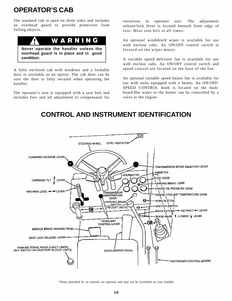
Optional Equipment Decals
AUXILIARY CONTROLSLEVER
OPERATION
LEFT/DOWN
RIGHT/UP9103-3417
Located on Instrument ConsolePart No. 9103-3417
AUXILIARY CONTROLS LEVER BUTTONOPERATION FUNCTIONS
LEFT/DOWN
9
Located on Instrument ConsolePart No. 9103-3394
ENERGIZE WHILE STARTING
ETHER
Located on DashboardPart No. 9108-3363
RIGHT/UP
CHECK TO ASSURE QUICK SWITCHPIN IS FULLY ENGAGED AND LOCKEDAFTER ATTACHMENT CHANGE.
Located on Boom HeadPart No. 9103-3023
Located on Seat PedestalPart No. 9102-3006
Located on AttachmentPart No. 9015-3001
GRADGRADGRADGRADGRADALLALLALLALLALL•
406 HILL AVE. S.W. NEW PHILADELPHIA. OHIO MADE IN U. S. A.
THE CAPACITY OF FORKLIFT. ATTACHMENT AND FORKCOMBINATION MAY BE LESS THAN THE CAPACITY SHOWN
ON ATTACHMENT - CONSULT FORKLIFT NAMEPLATEAND ALSO INSURE FORKS ARE OF PROPER SIZE.
9103-3394
ATTACHMENTSERIAL NUMBERWEIGHTCAPACITYHYD. PRESSURE
9102-3006
2-9103-3023
9015-3001
MAST
SIDESHIFT
SWING
PANELSUPPORT
OPERATOR’S CABThe standard cab is open on three sides and includesan overhead guard to provide protection fromfal l ing objects.
Never operate the handler unless theoverhead guard is in place and in goodcondition.
A fully enclosed cab with windows and a lockabledoor is available as an option. The cab door can besure the door is fully secured when operating thehandler.
The operator ’s seat is equipped with a seat belt andincludes fore and aft adjustment to compensaste for
variations in operator size. The adjustmentrelease/lock lever is located beneath front edge ofseat . Wear seat be l t a t a l l t imes.
An optional windshield wiper is available for usewith enclose cabs. An ON/OFF control switch isloca ted on the w iper moto r.
A variable speed defroster fan is available for usewith enclose cabs. An ON/OFF control switch andspeed contro l are located on the base of the fan.
An optional variable speed heater fan is available foruse with units equipped with a heater. An ON/OFF/SPEED CONTROL knob is located on the dash-board.Hot water to the heater can be controlled by avalve at the engine.
CONTROL AND INSTRUMENT IDENTIFICATION
*Items preceded by an asterisk are optional and may not be furnished on your handler
10
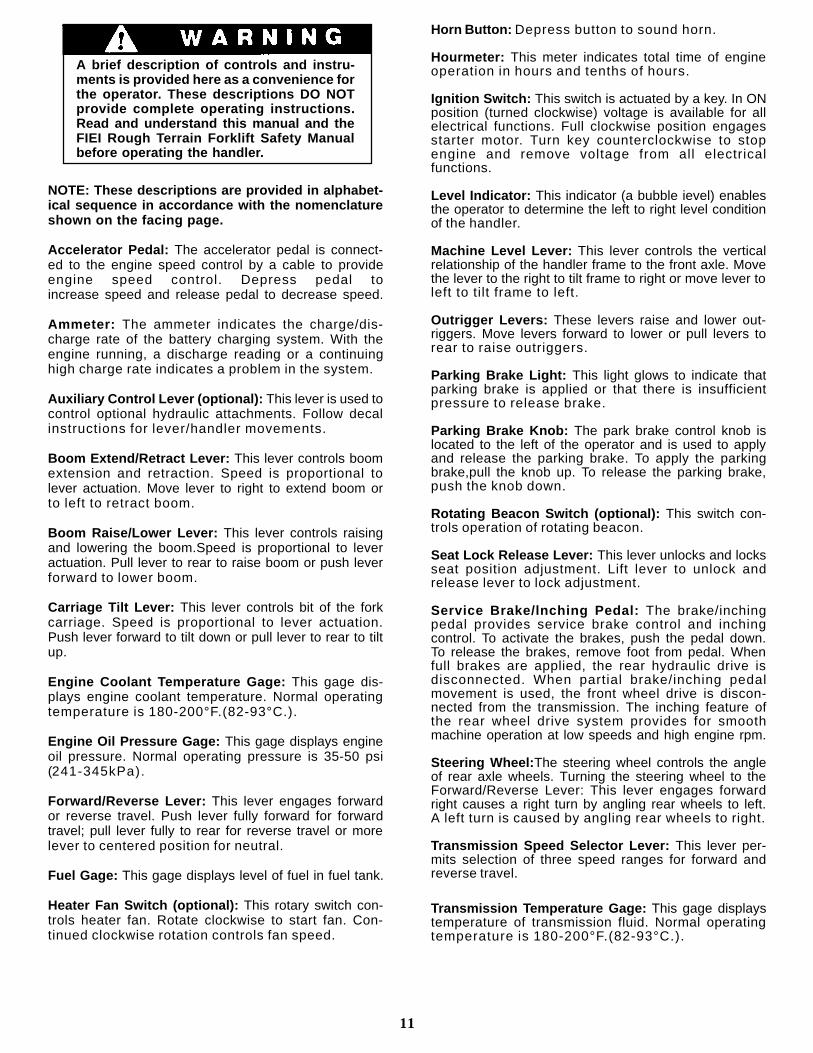
NOTE: These descriptions are provided in alphabet-ical sequence in accordance with the nomenclatureshown on the facing page.
Accelerator Pedal: The accelerator pedal is connect-ed to the engine speed control by a cable to provideengine speed control. Depress pedal toincrease speed and release pedal to decrease speed.
Ammeter: The ammeter indicates the charge/dis-charge rate of the battery charging system. With theengine running, a discharge reading or a continuinghigh charge rate indicates a problem in the system.
Auxiliary Control Lever (optional): This lever is used tocontrol optional hydraulic attachments. Follow decalinstructions for lever/handler movements.
Boom Extend/Retract Lever: This lever controls boomextension and retraction. Speed is proportional tolever actuation. Move lever to right to extend boom orto left to retract boom.
Boom Raise/Lower Lever: This lever controls raisingand lowering the boom.Speed is proportional to leveractuation. Pull lever to rear to raise boom or push leverforward to lower boom.
Carriage Tilt Lever: This lever controls bit of the forkcarriage. Speed is proportional to lever actuation.Push lever forward to tilt down or pull lever to rear to tiltup.
Engine Coolant Temperature Gage: This gage dis-plays engine coolant temperature. Normal operatingtemperature is 180-200°F.(82-93°C.).
Engine Oil Pressure Gage: This gage displays engineoil pressure. Normal operating pressure is 35-50 psi(241-345kPa).
Forward/Reverse Lever: This lever engages forwardor reverse travel. Push lever fully forward for forwardtravel; pull lever fully to rear for reverse travel or morelever to centered position for neutral.
Fuel Gage: This gage displays level of fuel in fuel tank.
Heater Fan Switch (optional): This rotary switch con-trols heater fan. Rotate clockwise to start fan. Con-tinued clockwise rotation controls fan speed.
A brief description of controls and instru-ments is provided here as a convenience forthe operator. These descriptions DO NOTprovide complete operating instructions.Read and understand this manual and theFIEI Rough Terrain Forklift Safety Manualbefore operating the handler.
Horn Button: Depress button to sound horn.
Hourmeter: This meter indicates total time of engineoperation in hours and tenths of hours.
Ignition Switch: This switch is actuated by a key. In ONposition (turned clockwise) voltage is available for allelectrical functions. Full clockwise position engagesstarter motor. Turn key counterclockwise to stopengine and remove voltage from all electricalfunctions.
Level Indicator: This indicator (a bubble ievel) enablesthe operator to determine the left to right level conditionof the handler.
Machine Level Lever: This lever controls the verticalrelationship of the handler frame to the front axle. Movethe lever to the right to tilt frame to right or move lever toleft to tilt frame to left.
Outrigger Levers: These levers raise and lower out-riggers. Move levers forward to lower or pull levers torear to raise outriggers.
Parking Brake Light: This light glows to indicate thatparking brake is applied or that there is insufficientpressure to release brake.
Parking Brake Knob: The park brake control knob islocated to the left of the operator and is used to applyand release the parking brake. To apply the parkingbrake,pull the knob up. To release the parking brake,push the knob down.
Rotating Beacon Switch (optional): This switch con-trols operation of rotating beacon.
Seat Lock Release Lever: This lever unlocks and locksseat position adjustment. Lift lever to unlock andrelease lever to lock adjustment.
Service Brake/lnching Pedal: The brake/inchingpedal provides service brake control and inchingcontrol. To activate the brakes, push the pedal down.To release the brakes, remove foot from pedal. Whenfull brakes are applied, the rear hydraulic drive isdisconnected. When partial brake/inching pedalmovement is used, the front wheel drive is discon-nected from the transmission. The inching feature ofthe rear wheel drive system provides for smoothmachine operation at low speeds and high engine rpm.
Steering Wheel: The steering wheel controls the angleof rear axle wheels. Turning the steering wheel to theForward/Reverse Lever: This lever engages forwardright causes a right turn by angling rear wheels to left.A left turn is caused by angling rear wheels to right.
Transmission Speed Selector Lever: This lever per-mits selection of three speed ranges for forward andreverse travel.
Transmission Temperature Gage: This gage displaystemperature of transmission fluid. Normal operatingtemperature is 180-200°F.(82-93°C.).
11
CHECKS AND SERVICESBEFORE STARTING ENGINE(To be performed at beginning of each work shift)
Use extreme caution when checking itemsbeyond your normal reach. Use anapproved safety ladder.
Before removing filler caps or fill plugs, wipe all dirtand grease away from the ports. If dirt is allowed to
Complete all required maintenance before operating unit.
enter these ports, it can shorten the life of o-rings,seals, packings and bearings.
When adding fluids or changing filter elements,refer to the lubrication section of this manual tode te rmine the p roper t ype to be used .
If spark arrestors are required, be sure they are inp lace and in good work ing order.
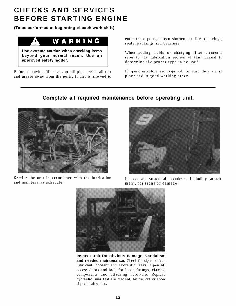
Service the unit in accordance with the lubricationand maintenance schedule.
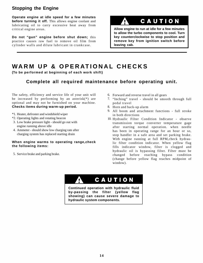
Inspect unit for obvious damage, vandalismand needed maintenance. Check for signs of fuel,lubricant, coolant and hydraulic leaks. Open allaccess doors and look for loose fittings, clamps,components and attaching hardware. Replacehydraulic lines that are cracked, brittle, cut or showsigns of abrasion.
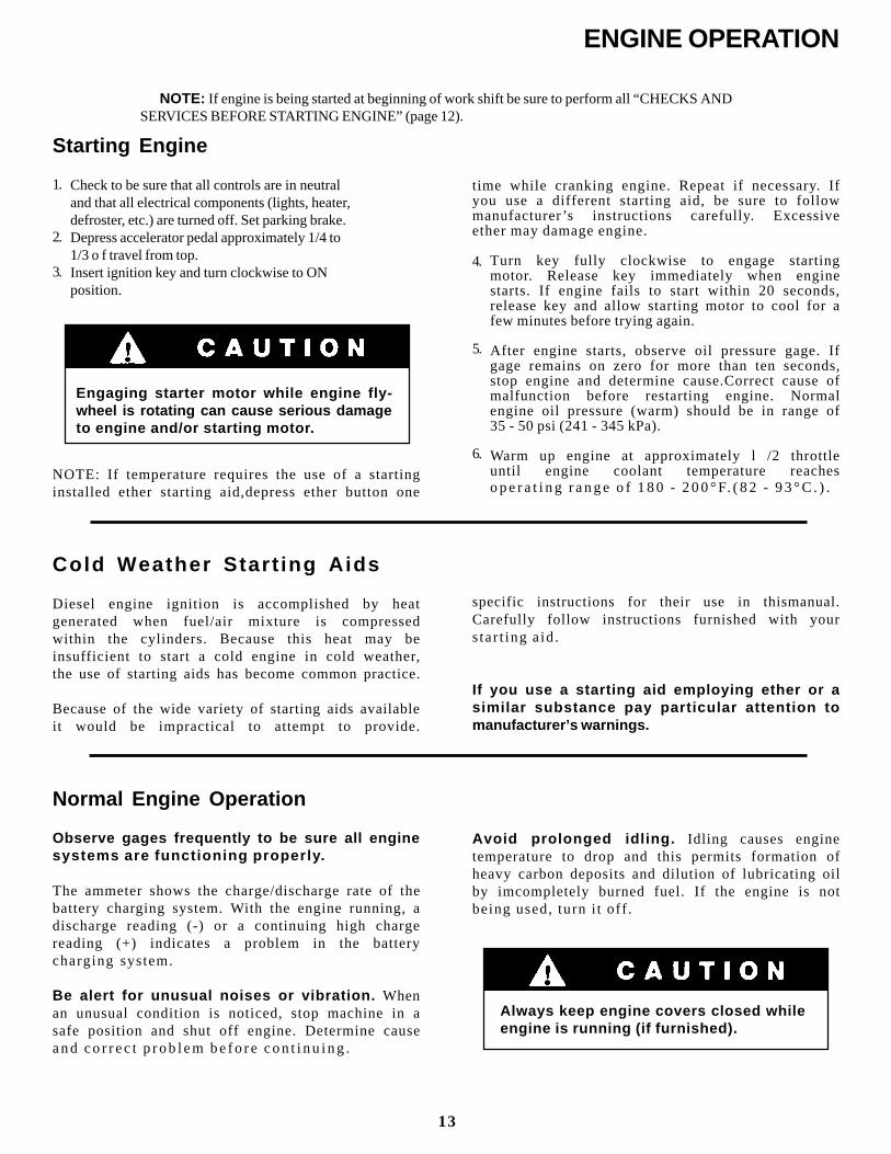
Inspect all structural members, including attach-men t , f o r s i gns o f damage .
12
Starting Engine
Check to be sure that all controls are in neutraland that all electrical components (lights, heater,defroster, etc.) are turned off. Set parking brake.Depress accelerator pedal approximately 1/4 to1/3 o f travel from top.Insert ignition key and turn clockwise to ONposition.
ENGINE OPERATION
NOTE: If engine is being started at beginning of work shift be sure to perform all “CHECKS AND SERVICES BEFORE STARTING ENGINE” (page 12).
Engaging starter motor while engine fly-wheel is rotating can cause serious damageto engine and/or starting motor.
NOTE: If temperature requires the use of a startinginstalled ether starting aid,depress ether button one
Cold Weather Star t ing Aids
Diesel engine ignition is accomplished by heatgenerated when fuel/air mixture is compressedwithin the cylinders. Because this heat may beinsufficient to start a cold engine in cold weather,the use of starting aids has become common practice.
Because of the wide variety of starting aids availableit would be impractical to attempt to provide.
Normal Engine Operation
Observe gages frequently to be sure all enginesystems are functioning properly.
The ammeter shows the charge/discharge rate of thebattery charging system. With the engine running, adischarge reading (-) or a continuing high chargereading (+) indicates a problem in the batterycharging system.
Be alert for unusual noises or vibration. Whenan unusual condition is noticed, stop machine in asafe position and shut off engine. Determine causeand co r rec t p rob lem be fo re con t i nu ing .
time while cranking engine. Repeat if necessary. Ifyou use a different starting aid, be sure to followmanufacturer ’s instructions carefully. Excessiveether may damage engine.
Turn key fully clockwise to engage startingmotor. Release key immediately when enginestarts. If engine fails to start within 20 seconds,release key and allow starting motor to cool for afew minutes before trying again.
After engine starts, observe oil pressure gage. Ifgage remains on zero for more than ten seconds,stop engine and determine cause.Correct cause ofmalfunction before restarting engine. Normalengine oil pressure (warm) should be in range of35 - 50 psi (241 - 345 kPa).
Warm up engine at approximately l /2 throttleuntil engine coolant temperature reacheso p e r a t i n g r a n g e o f 1 8 0 - 2 0 0 ° F. ( 8 2 - 9 3 ° C . ) .
Avoid prolonged idling. Idling causes enginetemperature to drop and this permits formation ofheavy carbon deposits and dilution of lubricating oilby imcompletely burned fuel. If the engine is notbeing used, turn i t of f .
Always keep engine covers closed whileengine is running (if furnished).
13
specific instructions for their use in thismanual.Carefully follow instructions furnished with yourstar t ing a id.
If you use a starting aid employing ether or asimilar substance pay particular attention tomanufacturer’s warnings.
1.
2.
3.4.
5.
6.
Stopping the Engine
Operate engine at idle speed for a few minutesbefore turning it off. This allows engine coolant andlubricating oil to carry excessive heat away fromcrit ical engine areas.
Do not “gun” engine before shut down; thispractice causes raw fuel to remove oil film fromcyl inder wal ls and di lute lubr icant in crankcase.
Allow engine to run at idle for a few minutesto allow the turbo components to cool. Turnkey counterclockwise to stop position andremove key from ignition switch beforeleaving cab.
WA R M U P & O P E R AT I O N A L C H E C K S(To be performed at beginning of each work shift)
Complete all required maintenance before operating unit.
The safety, efficiency and service life of your unit willbe increased by performing by an asterisk(*) areoptional and may not be furnished on your machine.Checks items during warm-up period.
Heater, defroster and windshield wiperOperating lights and rotating beaconLow brake pressure light - should go out withengine running above idleAmmeter - should show low charging rate aftercharging system has replaced starting drain
When engine warms to operating range,checkthe fol lowing items:
Service brake and parking brake.
Forward and reverse travel in all gears“Inching” travel - should be smooth through fullpedal travelHorn and back-up alarmAll boom and attachment functions - full strokein both directionsHydraulic Filter Condition Indicator - observetransmission torque converter temperature gageafter starting normal operation. when needlehas been in operating range for an hour or so,stop handler in a safe area and set parking brake.With engine running at full RPM,check hydrau-lic filter condition indicator. When yellow flagfills indicator window, filter is clogged andhydraulic oil is bypassing filter. Filter must bechanged before reaching bypass condition(change before yellow flag reaches midpoint ofwindow).
*1.*2. 3.
4.
5.
6.7.
8.9.
10.
Continued operation with hydraulic fluidby-passing the filter (yellow flagshowing) can cause severe damage tohydraulic system components.
14

BRAKE SYSTEM
General
The brake system furnished on the handler includes aservice brake and parking brake.
Because service braking and “inching” (slow travel)functions overlap, some features of inching will bediscussed here. Refer to Drive Train Section foradditional information on inching travel.
Inching Travel
Overlap between service braking and inching occursbecause the same foot pedal controls both functions,and also because both functions control travel speed.However, the methods of controlling travel speed arequite different: service braking involves a controlledstopping force applied to the front wheels whileinching involves a controlled driving force applied tothe rear wheels.
The service brake/inching pedal has three separatefunctions
It disconnects front drive axle from transmission.
It controls hydraulic flow to rear axle drive motors(hydraul ic f low regulates speed).
I t appl ies service brake.
Service Brakes
The service brake is applied to the front wheels of thehandler.
Oil for the brakes comes from the pilot circuit pump,thru an accumulator charging valve and the accumu-lator. When the service brake/inching pedal isdepressed far enough to actuate the brake valve, thehydraulic oil flows to the wet disc brakes in bothfront wheel hubs. The pressure compresses the brakediscs.
As illustrated, the three functions occur in sequenceas service brake/inching pedal is depressed from topto bottom of stroke.
Practice inching/braking in a safe, openarea until you are thoroughly familiar withresponse of machine to pedal travel.
15
Parking Brakes
Because the parking brake is spring-applied andhydraulically released,the engine must be running toprovide pressure to release parking brake.
On early units the parking brake is applied andreleased by a control valve knob located to the left ofthe operator’s seat. Raise knob to apply brake and pushknob down to release brake.
On recent units the parking brake is applied andreleased by a switch located on the dashboard. Depressright side of switch to apply brake and depress left sideof switch to release brake.
Always be certain to apply parking brake, stop engineand remove key from ignition switch before leavingoperator ’s cab.
1.
2.
3.
STEERING SYSTEM
Ninety degree rear wheel power steering is providedto reduce operator fatigue and to permit highmaneuverab i l i ty in c lose quar ters .
It is important that the operator practicemaneuvering the handler in a safe, open area untilhe becomes thoroughly familiar with steeringresponse and clearance required for tailswing andload when tu rn ing .
Be alert for any increase In effort needed tosteer. If any difference is noted, notifymaintenance personnel immediately forcorrection. If power assist feature shouldfail for any reason IT WOULD BECOMEVERY DIFFICULT TO STEER. For thisreason it is extremely important that youNEVER TURN ENGINE OFF WHILETRAVELING.
In the event power steering fails, stop assoon as possible. Do not drive unit untilproblem has been corrected.
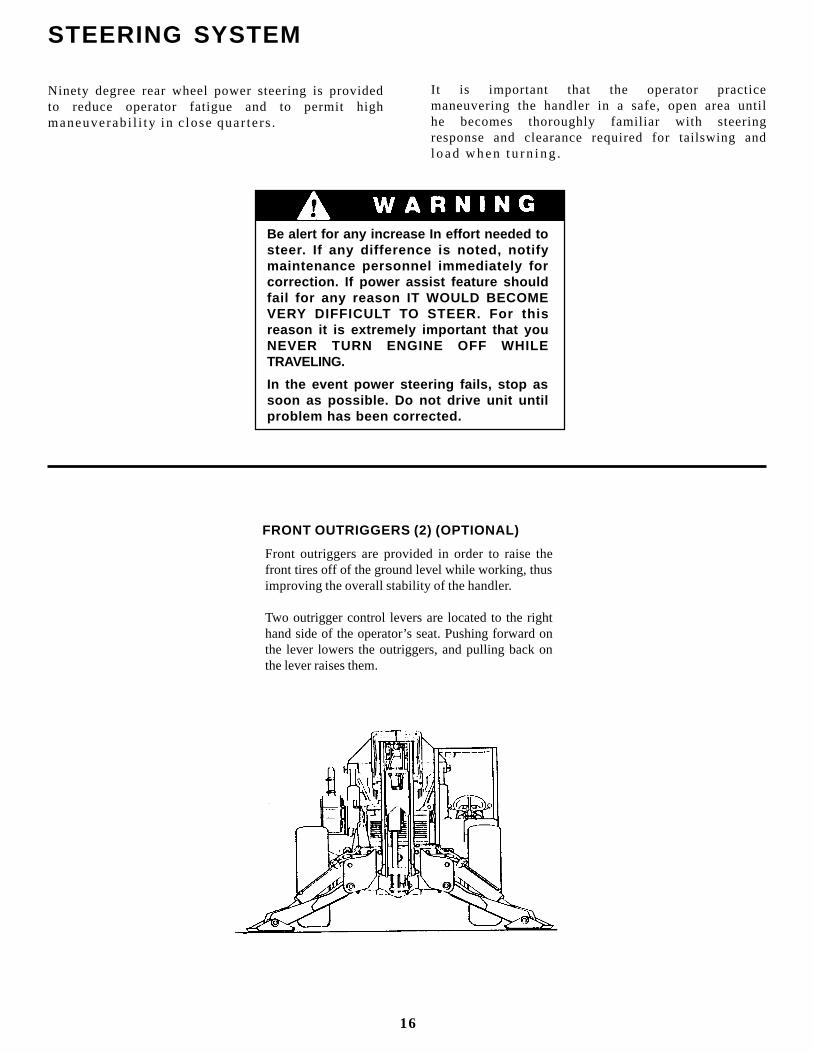
FRONT OUTRIGGERS (2) (OPTIONAL)
Front outriggers are provided in order to raise thefront tires off of the ground level while working, thusimproving the overall stability of the handler.
Two outrigger control levers are located to the righthand side of the operator’s seat. Pushing forward onthe lever lowers the outriggers, and pulling back onthe lever raises them.
16
General
The drive train provides two and four wheel driveincludes the engine torque converter trans-mission drive shaft and front and rear driving axles.
Inching travel is directly related to drive trainfunctions and wil l be discussed in this section.
Two & Four Wheel Drive
The drive train is designed to provide two wheeldrive (front axle driving? or four wheel drive (bothfront and rear axles driving).
Under certain conditions changing from four wheeldrive to two wheel drive may cause a difference inthe way the machine responds to steering brakingand drive controls. Always be aware of which travelmode you are using.
There are two ways to disengage rear wheeldrive:
Shift to third gear (rear axle drive is engaged onlyin first and second gears)
Disengage rear planetary hubs (refer to RearDrive Axle heading in this section).
NOTE: Rear drive axle can also be disengaged inresponse to overload in associated electrical circuitrycausing automatic reset type circuit breaker to trip(open). Breaker will close again in approximately tenseconds.
Torque Converter
There are no operator controls for the torqueconverter. It functions automatically to permitstarting from a standstill in any transmission speedrange.
An oil temperature gage is provided to indicateOperating temperature of torque converter/trans-mission. Normal operating temperature is 180 -200 ° F. (82 - 93 ° C.). If overheating occurs attemptto lower temperature by traveling in a lower gear. Ifnecessary stop and allow torque converter to coolwith engine running and gear selector in neutral. Besure oil cooler radiator f ins are clean.
DRIVE TRAIN
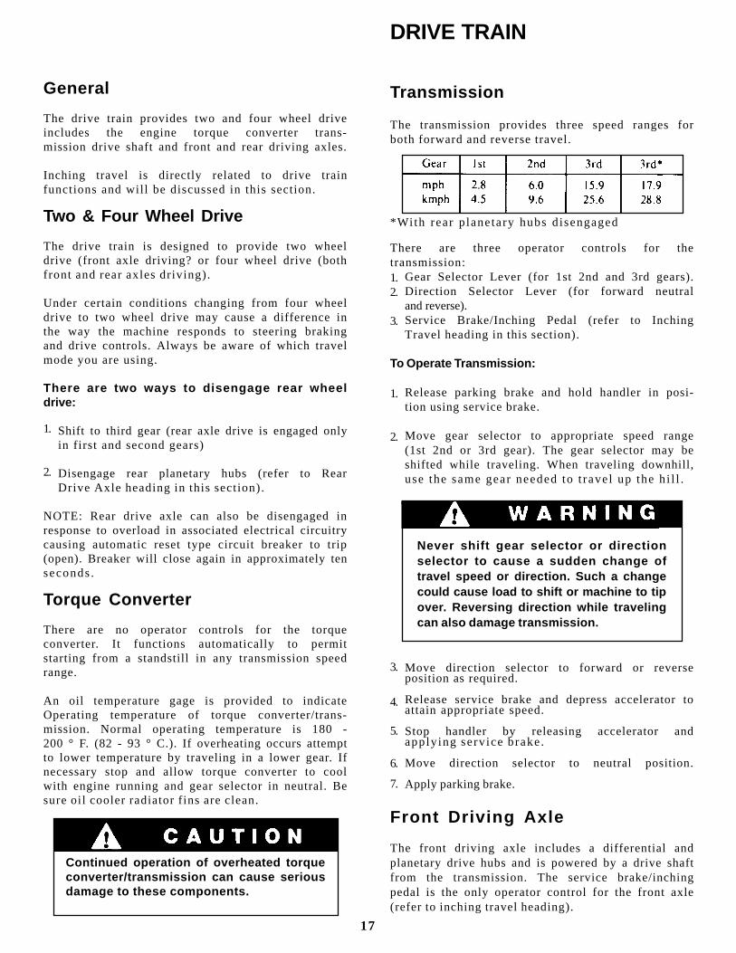
Transmission
The transmission provides three speed ranges forboth forward and reverse travel.
There are three operator controls for thetransmission:
Gear Selector Lever (for 1st 2nd and 3rd gears).Direction Selector Lever (for forward neutraland reverse).Service Brake/Inching Pedal (refer to InchingTravel heading in this section).
To Operate Transmission:
Release parking brake and hold handler in posi-tion using service brake.
Move gear selector to appropriate speed range(1st 2nd or 3rd gear). The gear selector may beshifted while traveling. When traveling downhill,use the same gear needed to t ravel up the h i l l .
Never shift gear selector or directionselector to cause a sudden change oftravel speed or direction. Such a changecould cause load to shift or machine to tipover. Reversing direction while travelingcan also damage transmission.
Move direction selector to forward or reverseposition as required.
Release service brake and depress accelerator toattain appropriate speed.
Stop handler by releasing accelerator andapply ing serv ice brake.
Move direction selector to neutral position.
Apply parking brake.
Front Driving Axle
The front driving axle includes a differential andplanetary drive hubs and is powered by a drive shaftfrom the transmission. The service brake/inchingpedal is the only operator control for the front axle(refer to inching travel heading).
3.
4.
5.
6.
7.
Continued operation of overheated torqueconverter/transmission can cause seriousdamage to these components.
1.
2.
1.
2.
*With rear p lanetary hubs d isengaged
1.2.
3.
17
Rear Driving Axle
The rear driving axle includes planetary hubs whichare powered by hydraulic motors mounted on theinner face of the hubs. Hydraulic flow to drivemotors is provided only in first and second gearspeed ranges. Drive motors are free- floating in thirdgear.
Continuous driving for two miles or morein third gear, with rear driving hubsengaged, can damage hydraulic drivemotors.
To Disengage Rear Driving Hubs:
Apply parking brake and remove key fromignition switch.
Remove cap screws from pin keeper plate.
Remove and rotate plate (cup out - engaged - cupin - disengaged).
Secure plate using cap screws.
Repeat procedure for other hub.
To engage Rear Driving Hubs: Repeat procedure.
NOTE: If machine is move with pin keeper plateremoved, input shaft pin wi l l pop out.
Hydraulic flow to rear axle drive motors is controlledelectrically. An automatic reset type breaker isincluded to prevent damage from overload. If circuitbreaker trips (opens) rear axle drive will beinoperative for approximately ten seconds untilbreaker resets. Notify maintenance personnel ifc i rcu i t b reaker t r ips repeated ly.
To determine whether circuit breaker has tripped,attempt to move machine using inching travel. Ifmachine does not respond to inching travel pedal.circuit breaker is open.
Inching Travel
Inching travel is provided to permit very slow travelwhile maintaining high engine speed for otherfunctions. Because inching travel depends onhydraulic flow to rear axle drive motors, inching
1.
2.
3.
4.
5.
travel functions only in first and second gears. Thereis no hydraul ic f low to dr ive motors in th i rd gear.
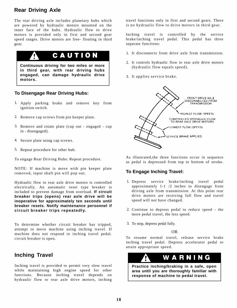
Inching travel is controlled by the servicebrake/inching travel pedal. This pedal has threeseparate functions:
It disconnects front drive axle from transmission.
It controls hydraulic flow to rear axle drive motors(hydraul ic f low equals speed).
I t appl ies service brake.
1.
2.
3.
As illustrated,the three functions occur in sequenceas pedal is depressed from top to bottom of stroke.
To Engage Inching Travel:
Depress service brake/inching travel pedalapproximately 1-1 /2 inches to disengage frontdriving axle from transmission. At this point reardrive motors are receiving full flow and travelspeed will not have changed.
Continue to depress pedal to reduce speed - themore pedal travel, the less speed.
To stop, depress pedal fully.
To resume normal travel, release service brakeinching travel pedal. Depress accelerator pedal toattain appropriate speed.
OR
Practice inching/braking in a safe, openarea until you are thoroughly familiar withresponse of machine to pedal travel.
1.
2.
3.
18
“LEVELING” means positioning the handler so thatit is level from side to side (left to right with respect toa man si t t ing in operator ’s seat).
A level indicator is located on upper portion of frontwindow frame to permit operator to determine thathandler frame is, or is not, level.
There are four very important things to rememberabout handler travell ing:
Never engage a load or lift a load more than fourfeet above ground level unless the handler is level.
A handler with the boom raised and/or an attach-ment instal led is a part ial ly loaded handler.
Once the handler frame has been leveled, and hasraised a load more than four feet above groundlevel, it must not be moved from its position ifsuch movement could change the level condition.
The combination of side tilt and load can cause the
handler to tip over.There a re two ways to leve l the hand le r :
The surface which will support the handler can beleveled. This method must be chosen if it will benecessary to move the handler from its positionafter the load has been raised over four feet fromground level - AND - such movement couldchange the level condit ion.
Remember, the supporting surface must be largeenough , smooth enough and firm enough to keephandler level when it is moved from its position.
The handler may be leveled by means of the frameleveling system. This method may be chosen whenit will not be necessary to move the handler fromits position after the load has been raised abovefour feet from ground level - OR - when suchmovement will not change the level condition ofthe handler.
LEVELING THE HANDLER
Leveling Handler Frame:
The handler is designed to permit tilting main frameeight degrees to left or right to compensate foruneven ground conditions.
The rear axle pivots at the midpoint of the mainframe to help assure that wheels will remain incontact with ground. A hydraulic cylinder providesa rigid connection between front axle and mainframe to help assure a solid work platform andpermit tilting main frame to left or right.
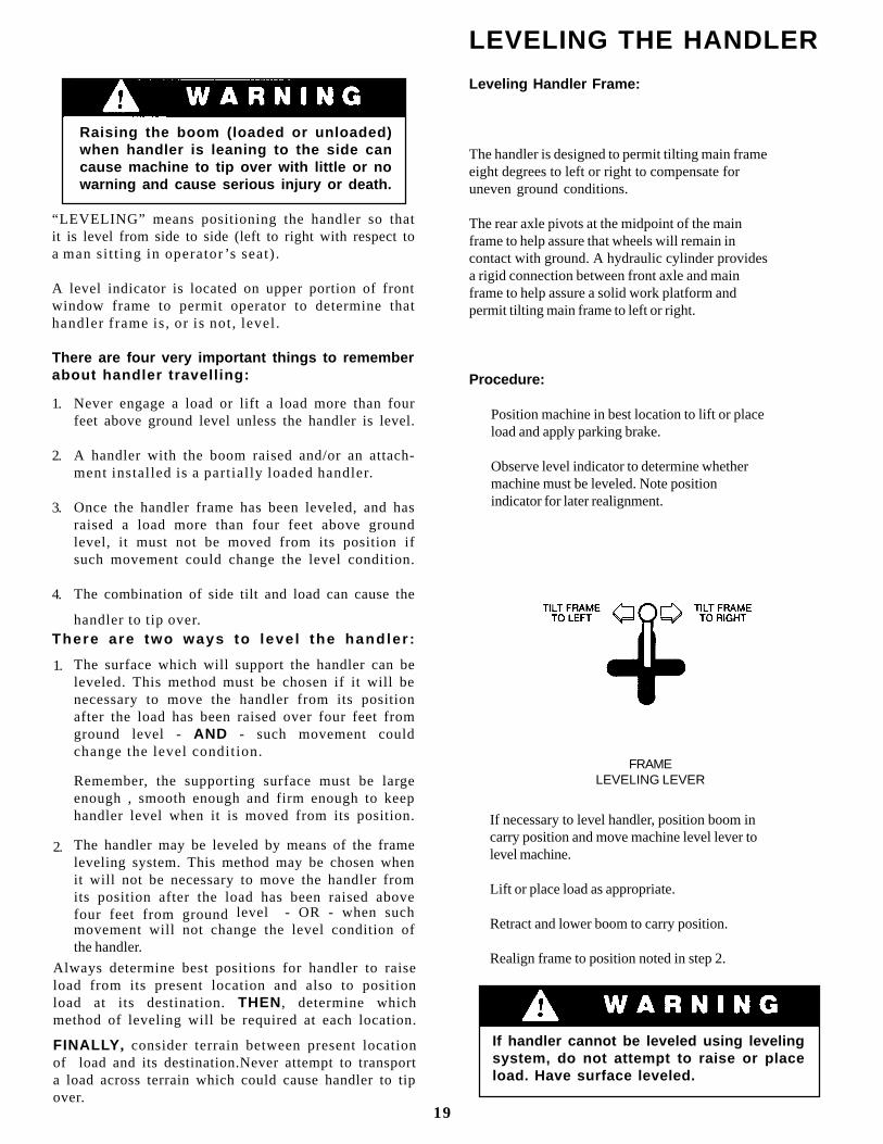
Procedure:
Position machine in best location to lift or placeload and apply parking brake.
Observe level indicator to determine whethermachine must be leveled. Note positionindicator for later realignment.
If necessary to level handler, position boom incarry position and move machine level lever tolevel machine.
Lift or place load as appropriate.
Retract and lower boom to carry position.
Realign frame to position noted in step 2.
FRAMELEVELING LEVER
If handler cannot be leveled using levelingsystem, do not attempt to raise or placeload. Have surface leveled.
1.
2.
3.
4.
19
Always determine best positions for handler to raiseload from its present location and also to positionload at its destination. THEN, determine whichmethod of leveling will be required at each location.
FINALLY , consider terrain between present locationof load and its destination.Never attempt to transporta load across terrain which could cause handler to tipover.
1.
2.
Raising the boom (loaded or unloaded)when handler is leaning to the side cancause machine to tip over with little or nowarning and cause serious injury or death.
This section highlights some common proceduresdiscusses areas which may be new to even theexperienced operator.
Hydraulic Controls
All boom and attachment movements are governedby hydraulic controls will cause rapid, jerky movementof the load. Such movements can cause the load toshift or fall or may cause the machine to tip over.
Feathering
Feathering is a control operation technique used forsmooth load handling. To feather controls, movecontrol lever very slowly until load begins to move,then gradually move lever further until load ismoving at desired speed. Gradually move levertoward neutral as load approaches destination.
Continue to reduce load speed to bring load to asmooth stop. Feathering effect can be increased bylowering engine speed at beginning and near end ofload movement.
Boom Control Lever
The boom control lever can be positioned to causeindividual boom movements or combinations ofboom movements as i l lustrated.
OPERATING PROCEDURES & TECHNIQUES
With boom raised above horizontal, forks can beinserted under a load by moving boom control leverforward and to the right until forks move forwardhorizontally.
With boom raised above horizontal, forks can beremoved from a load by moving boom control leverback and to the left until forks move rearwardhorizontally.
With boom lowered below horizontal, fork can beinserted under a load by moving boom control leverback and to the right until forks move forwardhorizontally.
With boom lowered below horizontal, forks can beremoved from load by moving boom control leverforward and to the left until forks move rearwardhorizontally.
The closer the boom to horizontal, the less boomraise/lower movement required for inserting andremoving forks.
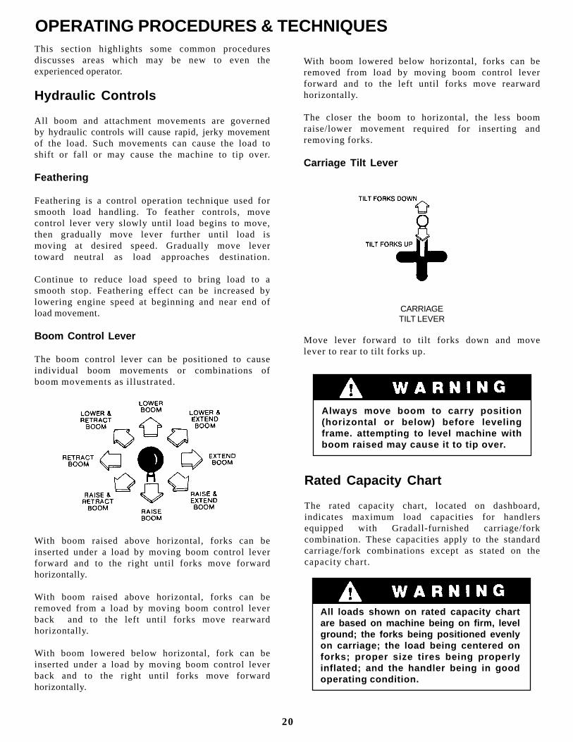
Carriage Tilt Lever
Move lever forward to tilt forks down and movelever to rear to ti lt forks up.
CARRIAGETILT LEVER
Rated Capacity Chart
The rated capacity chart, located on dashboard,indicates maximum load capacities for handlersequipped with Gradall-furnished carriage/forkcombination. These capacities apply to the standardcarriage/fork combinations except as stated on thecapacity chart.
Always move boom to carry position(horizontal or below) before levelingframe. attempting to level machine withboom raised may cause it to tip over.
All loads shown on rated capacity chartare based on machine being on firm, levelground; the forks being positioned evenlyon carriage; the load being centered onforks; proper size tires being properlyinflated; and the handler being in goodoperating condition.
20
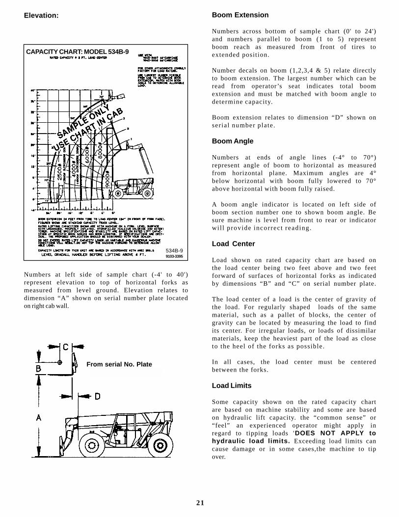
Elevation:
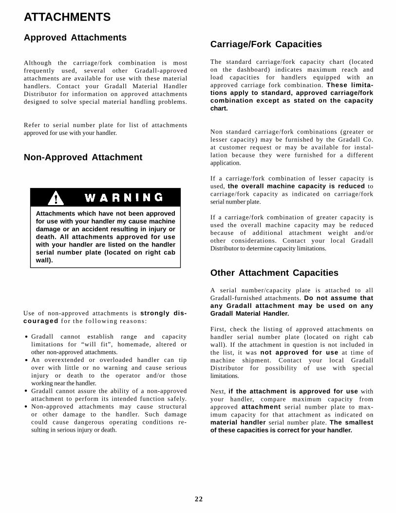
Numbers at left side of sample chart (-4' to 40')represent elevation to top of horizontal forks asmeasured from level ground. Elevation relates todimension “A” shown on serial number plate locatedon right cab wall.
Boom Extension
Numbers across bottom of sample chart (0' to 24')and numbers parallel to boom (1 to 5) representboom reach as measured from front of tires toextended posit ion.
Number decals on boom (1,2,3,4 & 5) relate directlyto boom extension. The largest number which can beread from operator ’s seat indicates total boomextension and must be matched with boom angle todetermine capacity.
Boom extension relates to dimension “D” shown onser ial number plate.
Boom Angle
Numbers at ends of angle lines (-4° to 70°)represent angle of boom to horizontal as measuredfrom horizontal plane. Maximum angles are 4°below horizontal with boom fully lowered to 70°above horizontal with boom fully raised.
A boom angle indicator is located on left side ofboom section number one to shown boom angle. Besure machine is level from front to rear or indicatorwi l l prov ide incorrect reading.
Load Center
Load shown on rated capacity chart are based onthe load center being two feet above and two feetforward of surfaces of horizontal forks as indicatedby dimensions “B” and “C” on serial number plate.
The load center of a load is the center of gravity ofthe load. For regularly shaped loads of the samematerial, such as a pallet of blocks, the center ofgravity can be located by measuring the load to findits center. For irregular loads, or loads of dissimilarmaterials, keep the heaviest part of the load as closeto the heel of the forks as possible.
In all cases, the load center must be centeredbetween the forks.
Load Limits
Some capacity shown on the rated capacity chartare based on machine stability and some are basedon hydraulic lift capacity. the “common sense” or“feel” an experienced operator might apply inregard to tipping loads ‘DOES NOT APPLY tohydraulic load limits. Exceeding load limits cancause damage or in some cases,the machine to tipover.
From serial No. Plate
CAPACITY CHART: MODEL 534B-9
534B-99103-3395
534B-99103-3395
21
ATTACHMENTS
Approved Attachments
Although the carriage/fork combination is mostfrequently used, several other Gradall-approvedattachments are available for use with these materialhandlers. Contact your Gradall Material HandlerDistributor for information on approved attachmentsdesigned to solve special material handling problems.
Refer to serial number plate for list of attachmentsapproved for use with your handler.
Non-Approved Attachment
Carriage/Fork Capacities
The standard carriage/fork capacity chart (locatedon the dashboard) indicates maximum reach andload capacities for handlers equipped with anapproved carriage fork combination. These limita-tions apply to standard, approved carriage/forkcombination except as stated on the capacitychart.
Non standard carriage/fork combinations (greater orlesser capacity) may be furnished by the Gradall Co.at customer request or may be available for instal-lation because they were furnished for a differentapplication.
If a carriage/fork combination of lesser capacity isused, the overall machine capacity is reduced tocarriage/fork capacity as indicated on carriage/forkserial number plate.
If a carriage/fork combination of greater capacity isused the overall machine capacity may be reducedbecause of additional attachment weight and/orother considerations. Contact your local GradallDistributor to determine capacity limitations.
Other Attachment Capacities
A serial number/capacity plate is attached to allGradall-furnished attachments. Do not assume thatany Gradall attachment may be used on anyGradall Material Handler.
First, check the listing of approved attachments onhandler serial number plate (located on right cabwall). If the attachment in question is not included inthe list, it was not approved for use at time ofmachine shipment. Contact your local GradallDistributor for possibility of use with speciallimitations.
Next, if the attachment is approved for use withyour handler, compare maximum capacity fromapproved attachment serial number plate to max-imum capacity for that attachment as indicated onmaterial handler serial number plate. The smallestof these capacities is correct for your handler.
Attachments which have not been approvedfor use with your handler my cause machinedamage or an accident resulting in injury ordeath. All attachments approved for usewith your handler are listed on the handlerserial number plate (located on right cabwall).
•
•
•
•
Use of non-approved attachments is strongly dis-couraged fo r the fo l low ing reasons :
Gradall cannot establish range and capacitylimitations for “will fit”, homemade, altered orother non-approved attachments.An overextended or overloaded handler can tipover with little or no warning and cause seriousinjury or death to the operator and/or thoseworking near the handler.Gradall cannot assure the ability of a non-approvedattachment to perform its intended function safely.Non-approved attachments may cause structuralor other damage to the handler. Such damagecould cause dangerous operating conditions re-sulting in serious injury or death.
22
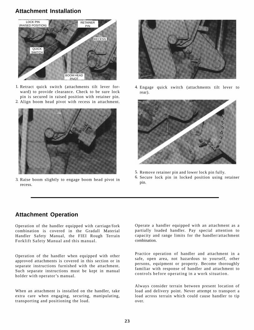
Attachment Installation
LOCK PIN(RAISED POSITION)
RETAINERPIN
QUICKSWITCH
RECESS
BOOM HEADPIVOT
Retract quick switch (attachments tilt lever for-ward) to provide clearance. Check to be sure lockpin is secured in raised position with retainer pin.Align boom head pivot with recess in attachment.
1.
2.
Raise boom slightly to engage boom head pivot inrecess.
3.
Engage quick switch (attachments tilt lever torear).
Remove retainer pin and lower lock pin fully.Secure lock pin in locked position using retainerpin.
4.
5.6.
Attachment Operation
Operation of the handler equipped with carriage/forkcombination is covered in the Gradall MaterialHandler Safety Manual, the FIEI Rough TerrainForkl i f t Safety Manual and th is manual .
Operation of the handler when equipped with otherapproved attachments is covered in this section or inseparate instructions furnished with the attachment.Such separate instructions must be kept in manualholder with operator ’s manual.
When an attachment is installed on the handler, takeextra care when engaging, securing, manipulating,transporting and positioning the load.
Operate a handler equipped with an attachment as apartially loaded handler. Pay special attention tocapacity and range limits for the handler/attachmentcombination.
Practice operation of handler and attachment in asafe, open area, not hazardous to yourself, otherpersons, equipment or property. Become thoroughlyfamiliar with response of handler and attachment tocontro ls before operat ing in a work s i tuat ion.
Always consider terrain between present location ofload and delivery point. Never attempt to transport aload across terrain which could cause handler to tipover.
23
FORK POSITIONER
Capacity:
Maximum load capacity for fork positioner carriageis the same as standard carriage without fork posi-tioner (refer to basic Capacity Chart located ondashboard.) Capacity varies with boom extensionand elevation positions.
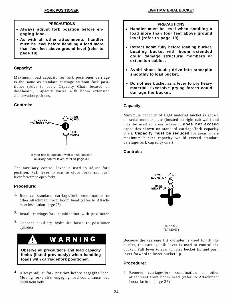
Controls:
If your unit is equipped with a multi-functionauxiliary control lever, refer to page 30.
The auxiliary control lever is used to adjust forkposition. Pull lever to rear to close forks and pushlever forward to open forks.
Procedure:
Remove standard carriage/fork combination orother attachment from boom head (refer to Attach-ment Installation - page 23).
Install carriage/fork combination with positioner.
Connect auxiliary hydraulic hoses to positionercylinders.
Always adjust fork position before engaging load.Moving forks after engaging load could cause loadto fall from forks.
PRECAUTIONS
Always adjust fork position before en-gaging load.
As with all other attachments, handlermust be level before handling a load morethan four feet above ground level (refer topage 19).
•
•
Observe all precautions and load capacitylimits (listed previously) when handlingloads with carriage/fork positioner.
LIGHT MATERIAL BUCKET
Capacity:
Maximum capacity of light material bucket is shownon serial number plate (located on right cab wall) andmay be used in areas where it does not exceedcapacities shown on standard carriage/fork capacitychart. Capacity must be reduced for areas wheremaximum bucket capacity would exceed standardcarriage/fork capacity chart.
Controls:
CARRIAGETILT LEVER
Because the carriage tilt cylinder is used to tilt thebucket, the carriage tilt lever is used to control thebucket. Pull lever to rear to raise bucket lip and pushlever forward to lower bucket lip.
Procedure:
Remove carriage/fork combination or otherattachment from boom head (refer to AttachmentInstal lat ion - page 23).
PRECAUTIONSHandler must be level when handling aload more than four feet above groundlevel (refer to page 19).
Retract boom fully before loading bucket.Loading bucket with boom extendedcould damage structural members orextension cables.
Avoid shock loads; drive into stockpilesmoothly to load bucket.
Do not use bucket as a lever to pry heavymaterial. Excessive prying forces coulddamage the bucket.
1.
2.
3.
4. 1.
•
•
•
•
24
Install light material bucket on boom head.
Retract boom fully and tilt bucket up or down asrequired to position bottom of bucket parallel withground.
Raise or lower boom to appropriate height forloading material from stockpile.
Align handler with face of stockpile and driveslowly and smoothly into pile to load bucket.
Tilt bucket up far enough to retain load and backaway from pile.
Lower bucket to carry position (approximatelyone foot above ground) and travel carefully tounloading point. Tilt bucket down to dump load.
Observe all precautions and load capacitylimits (listed previously) when handlingloads with light material bucket.
Light back-blading of loose material ispermissible but heavier grading operationsmay damage the bucket and structuralmembers.
MAST (6' with 48" or 66" carriage)
PRECAUTIONS
Read additional capacity informationunder Capacity heading.
Because the mast increases lift height, itis especially important to level thehandler before lifting a load more thanfour feet above ground level (refer to page19).
•
•
Capacity:
Maximum lift capacity for the mast is shown on serialnumber plate (located on right cab wall). However,maximum lift capacity applies only to certain areaswithin boom extension/elevation pattern of handler/
mast combination. A separate capacity chart must beused for handlers equipped with mast. Study thischart carefully before attempting to handle a loadwi th mast a t tachment .
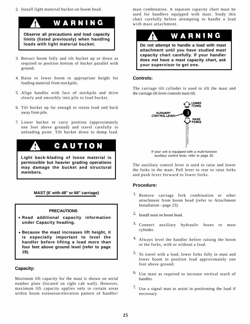
Controls:
The carriage tilt cylinder is used to tilt the mast andthe carriage tilt lever controls mast tilt.
If your unit is equipped with a multi-functionauxiliary control lever, refer to page 30.
The auxiliary control lever is used to raise and lowerthe forks in the mast. Pull lever to rear to raise forksand push lever forward to lower forks.
Procedure:
Remove carriage fork combination or otherattachment from boom head (refer to AttachmentInstallation - page 23).
Install mast on boom head.
Connect auxiliary hydraulic hoses to mastcylinder.
Always level the handler before raising the boomor the forks, with or without a load.
To travel with a load, lower forks fully in mast andlower boom to position load approximately onefoot above ground.
Use mast as required to increase vertical reach ofhandler.
Use a signal man to assist in positioning the load ifnecessary.
1.
2.
3.
4.
5.
6.
7.
2.
3.
4.
5.
6.
7.
Do not attempt to handle a load with mastattachment until you have studied mastcapacity chart carefully. If your handlerdoes not have a mast capacity chart, askyour supervisor to get one.
25
SWING FORKS
PRECAUTIONS
Read addi t ional capaci ty in format ionunder Capacity heading.
Always level forks (horizontally) beforesw ing ing l oad to s ide . Sw ing ing un -leveled forks may result in load slippingfrom forks.
Because the swing forks can swing theload to the side, it is especially importantthat the handler be level when handling aload more than four feet above groundlevel (refer to page 19).
Capacity:
Maximum lift capacity for swing forks is shown onserial number plate (located on right cab wall).However, maximum lift capacity applies only tocertain areas within boom extension/elevation pat-tern of handler/swing fork combination. A separatecapacity chart must be used for handlers equippedwith swing forks. Study this chart carefully beforeattempting to handle a load with swing forkattachment.
Do not attempt to handle a load with swingfork at tachment unt i l you have studiedswing fork capacity chart carefully. If yourhandler does not have a swing fork capacitychart, ask your supervisor to get one.
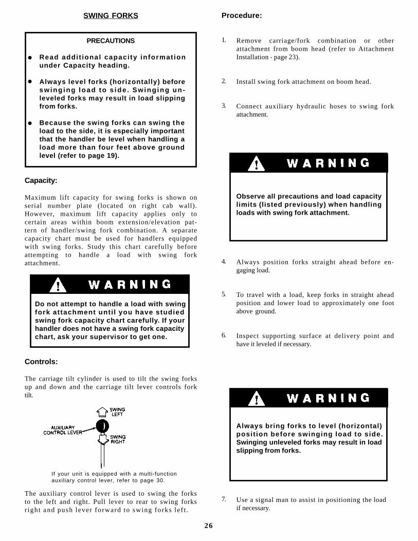
Controls:
The carriage tilt cylinder is used to tilt the swing forksup and down and the carriage tilt lever controls forktilt.
The auxiliary control lever is used to swing the forksto the left and right. Pull lever to rear to swing forksr ight and push lever forward to swing forks lef t .
l
l
l
Procedure:
Remove carriage/fork combination or otherattachment from boom head (refer to AttachmentInstallation - page 23).
Install swing fork attachment on boom head.
Connect auxiliary hydraulic hoses to swing forkattachment.
Observe all precautions and load capacitylimits (listed previously) when handlingloads with swing fork attachment.
Always position forks straight ahead before en-gaging load.
To travel with a load, keep forks in straight aheadposition and lower load to approximately one footabove ground.
Inspect supporting surface at delivery point andhave it leveled if necessary.
Always bring forks to level (horizontal)posi t ion before swinging load to s ide.Swinging unleveled forks may result in loadslipping from forks.
Use a signal man to assist in positioning the loadif necessary.
If your unit is equipped with a multi-functionauxiliary control lever, refer to page 30.
26
1.
2.
3.
4.
5.
6.
7.
SLOPE PILE CARRIAGE
PRECAUTIONS
Level handler before t i l t ing carr iage toengage load (refer to page 19).
Always level handler before lifting a loadmore than four feet above ground.
Capacity:
Maximum load capacity for slope pile carriage isshown on serial number plate (located on right cabwall). However, maximum capacity may be usedonly in areas where it does not exceed capacitiesshown on standard carriage/fork capacity chart(located on dashboard). Follow standard chart todetermine capacities for other areas of boomextension/elevation pattern.
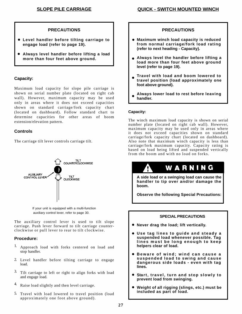
Controls
The carriage tilt lever controls carriage tilt.
If your unit is equipped with a multi-function auxiliary control lever, refer to page 30.
The auxiliary control lever is used to tilt slopecarriage. Push lever forward to tilt carriage counter-clockwise or pul l lever to rear to t i l t c lockwise.
Procedure:
Approach load with forks centered on load andstop handler.
Level handler before tilting carriage to engageload.
Tilt carriage to left or right to align forks with loadand engage load.
Raise load slightly and then level carriage.
Travel with load lowered to travel position (loadapproximately one foot above ground).
l
l
QUICK - SWITCH MOUNTED WINCH
PRECAUTIONS
Maximum winch load capacity is reducedfrom normal carr iage/fork load rat ing(refer to next heading - Capacity).
Always level the handler before lifting aload more than four feet above groundlevel (refer to page 19).
Travel with load and boom lowered totravel position (load approximately onefoot above ground).
Always lower load to rest before leavinghandler.
Capacity:
The winch maximum load capacity is shown on serialnumber plate (located on right cab wall). However,maximum capacity may be used only in areas whereit does not exceed capacities shown on standardcarriage/fork capacity chart (located on dashboard).Also note that maximum winch capacity is less thancarriage/fork maximum capacity. Capacity rating isbased on load being lifted and suspended verticallyf rom the boom and wi th no load on forks.
A side load or a swinging load can cause thehandler to t ip over and/or damage theboom.
Observe the following Special Precautions:
SPECIAL PRECAUTIONS
Never drag the load; lift vertically.
U s e t a g l i n e s t o g u i d e a n d s t e a d y asuspended load whenever possible. Tagl i n e s m u s t b e l o n g e n o u g h t o k e e phelpers clear of load.
B e w a r e o f w i n d ; w i n d c a n c a u s e as u s p e n d e d l o a d t o s w i n g a n d c a u s edangerous s ide loads - even wi th taglines.
Sta r t , t r ave l , t u rn and s top s low ly toprevent load from swinging.
Weight of all rigging (slings, etc.) must beincluded as part of load.
27
l
l
l
l
l
l
l
l
l
1.
2.
3.
4.
5.
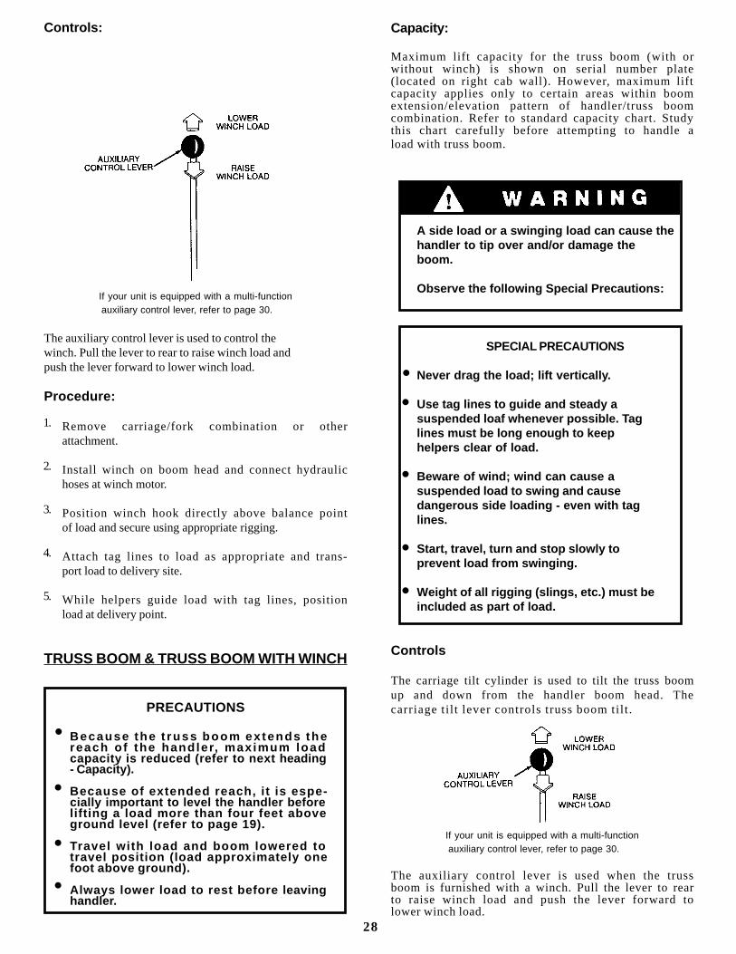
Controls:
If your unit is equipped with a multi-function auxiliary control lever, refer to page 30.
The auxiliary control lever is used to control thewinch. Pull the lever to rear to raise winch load andpush the lever forward to lower winch load.
Procedure:
Remove carriage/fork combination or otherattachment.
Install winch on boom head and connect hydraulichoses at winch motor.
Position winch hook directly above balance pointof load and secure using appropriate rigging.
Attach tag lines to load as appropriate and trans-port load to delivery site.
While helpers guide load with tag lines, positionload at delivery point.
TRUSS BOOM & TRUSS BOOM WITH WINCH
PRECAUTIONS
Because the t russ boom ex tends thereach o f the hand ler, max imum loadcapacity is reduced (refer to next heading- Capacity).
Because of extended reach, i t is espe-cially important to level the handler beforelifting a load more than four feet aboveground level (refer to page 19).
Travel with load and boom lowered totravel position (load approximately onefoot above ground).
Always lower load to rest before leavinghandler.
Capacity:
Maximum lift capacity for the truss boom (with orwithout winch) is shown on serial number plate(located on right cab wall). However, maximum liftcapacity applies only to certain areas within boomextension/elevation pattern of handler/truss boomcombination. Refer to standard capacity chart. Studythis chart carefully before attempting to handle aload with truss boom.
A side load or a swinging load can cause thehandler to tip over and/or damage theboom.
Observe the following Special Precautions:
SPECIAL PRECAUTIONS
Never drag the load; lift vertically.
Use tag lines to guide and steady asuspended loaf whenever possible. Taglines must be long enough to keephelpers clear of load.
Beware of wind; wind can cause asuspended load to swing and causedangerous side loading - even with taglines.
Start, travel, turn and stop slowly toprevent load from swinging.
Weight of all rigging (slings, etc.) must beincluded as part of load.
Controls
The carriage tilt cylinder is used to tilt the truss boomup and down from the handler boom head. Thecarriage t i l t lever controls truss boom ti l t .
If your unit is equipped with a multi-function auxiliary control lever, refer to page 30.
The auxiliary control lever is used when the trussboom is furnished with a winch. Pull the lever to rearto raise winch load and push the lever forward tolower winch load.
l
l
l
l
28
l
l
l
l
l
1.
2.
3.
4.
5.
Procedure:
Remove carriage/fork combination or otherattachment from boom head (refer to attachmentinstallation - page 23).
Install truss boom on boom head.
If truss boom winch is furnished, connect auxiliaryhydraulic hoses to winch.
Approach truss or truss bundle with boom aboveand parallel to load.
Position truss boom approximately parallel withmain boom.
Position truss boom/winch hook as close aspossible to balance point of load and secure load toboom using short slings or other rigging. Be surerigging will not allow load to slip in any direction.
Open clamps at heel of truss boom far enough toclear load and tilt truss boom up until truss/bundlecontacts heel of truss boom.
Close clamps to hold load lightly and secureclamps.
Transport load to delivery site and attach tag linesif load will be freely suspended.
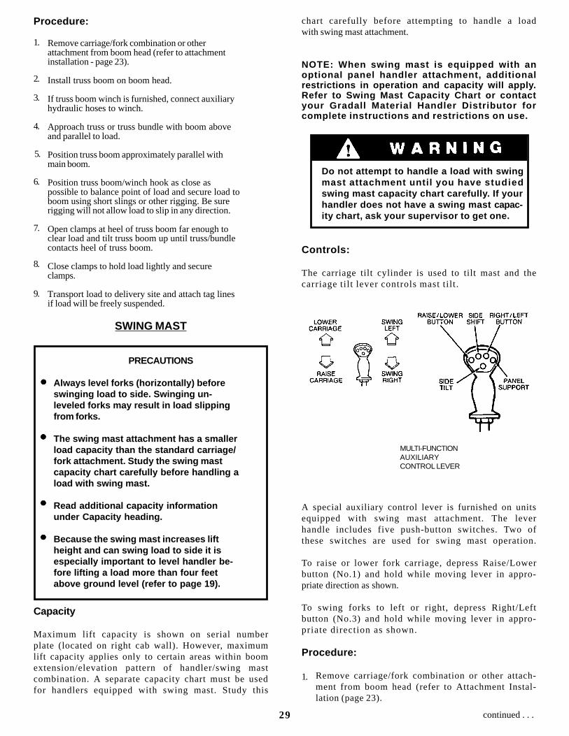
SWING MAST
PRECAUTIONS
Always level forks (horizontally) beforeswinging load to side. Swinging un-leveled forks may result in load slippingfrom forks.
The swing mast attachment has a smallerload capacity than the standard carriage/fork attachment. Study the swing mastcapacity chart carefully before handling aload with swing mast.
Read additional capacity informationunder Capacity heading.
Because the swing mast increases liftheight and can swing load to side it isespecially important to level handler be-fore lifting a load more than four feetabove ground level (refer to page 19).
Capacity
Maximum lift capacity is shown on serial numberplate (located on right cab wall). However, maximumlift capacity applies only to certain areas within boomextension/elevation pattern of handler/swing mastcombination. A separate capacity chart must be usedfor handlers equipped with swing mast. Study this
chart carefully before attempting to handle a loadwith swing mast attachment.
NOTE: When swing mast is equipped with anoptional panel handler attachment, additionalrestrictions in operation and capacity will apply.Refer to Swing Mast Capacity Chart or contactyour Gradall Material Handler Distributor forcomplete instructions and restrictions on use.
Do not attempt to handle a load with swingmast attachment unti l you have studiedswing mast capacity chart carefully. If yourhandler does not have a swing mast capac-ity chart, ask your supervisor to get one.
Controls:
The carriage tilt cylinder is used to tilt mast and thecarriage ti l t lever controls mast t i l t .
A special auxiliary control lever is furnished on unitsequipped with swing mast attachment. The leverhandle includes five push-button switches. Two ofthese switches are used for swing mast operation.
To raise or lower fork carriage, depress Raise/Lowerbutton (No.1) and hold while moving lever in appro-priate direction as shown.
To swing forks to left or right, depress Right/Leftbutton (No.3) and hold while moving lever in appro-priate direction as shown.
Procedure:
Remove carriage/fork combination or other attach-ment from boom head (refer to Attachment Instal-lation (page 23).
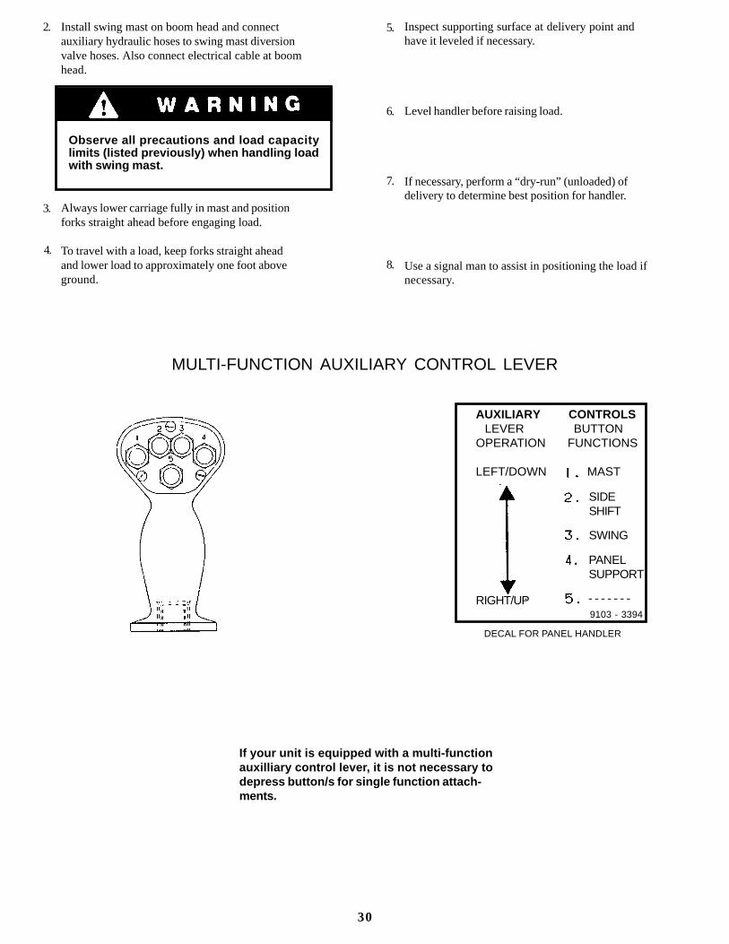
MULTI-FUNCTIONAUXILIARYCONTROL LEVER
lllll
lllll
lllll
lllll
1.
1.
2.
3.
4.
5.
6.
7.
8.
9.
29 continued . . .
Install swing mast on boom head and connectauxiliary hydraulic hoses to swing mast diversionvalve hoses. Also connect electrical cable at boomhead.
Observe all precautions and load capacitylimits (listed previously) when handling loadwith swing mast.
Always lower carriage fully in mast and positionforks straight ahead before engaging load.
To travel with a load, keep forks straight aheadand lower load to approximately one foot aboveground.
Inspect supporting surface at delivery point andhave it leveled if necessary.
Level handler before raising load.
If necessary, perform a “dry-run” (unloaded) ofdelivery to determine best position for handler.
Use a signal man to assist in positioning the load ifnecessary.
2.
3.
4.
5.
6.
7.
8.
If your unit is equipped with a multi-functionauxilliary control lever, it is not necessary todepress button/s for single function attach-ments.
MULTI-FUNCTION AUXILIARY CONTROL LEVER
AUXILIARY CONTROLS LEVER BUTTONOPERATION FUNCTIONS
LEFT/DOWN MAST
RIGHT/UP9103 - 3394
SIDESHIFT
SWING
PANELSUPPORT
- - - - - - -
DECAL FOR PANEL HANDLER
30
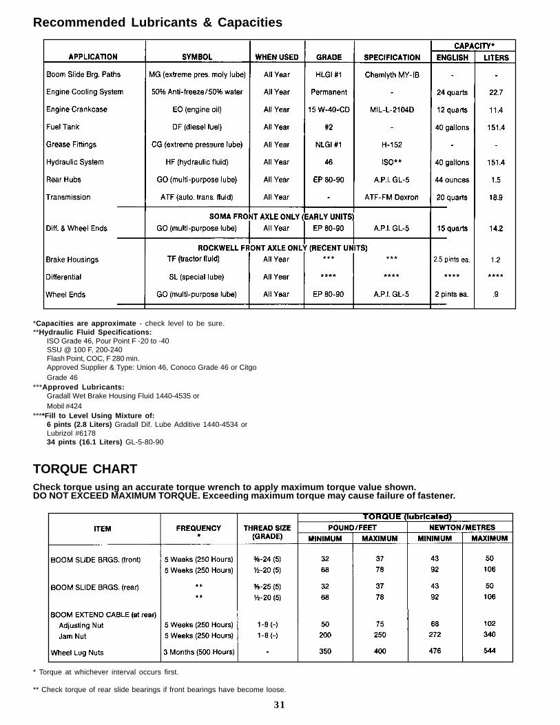
Recommended Lubricants & Capacities
*Capacities are approximate - check level to be sure.**Hydraulic Fluid Specifications:
ISO Grade 46, Pour Point F -20 to -40SSU @ 100 F, 200-240Flash Point, COC, F 280 min.Approved Supplier & Type: Union 46, Conoco Grade 46 or CitgoGrade 46
***Approved Lubricants:Gradall Wet Brake Housing Fluid 1440-4535 orMobil #424
****Fill to Level Using Mixture of:6 pints (2.8 Liters) Gradall Dif. Lube Additive 1440-4534 orLubrizol #617834 pints (16.1 Liters) GL-5-80-90
TORQUE CHARTCheck torque using an accurate torque wrench to apply maximum torque value shown.DO NOT EXCEED MAXIMUM TORQUE. Exceeding maximum torque may cause failure of fastener.
* Torque at whichever interval occurs first.
** Check torque of rear slide bearings if front bearings have become loose.
31
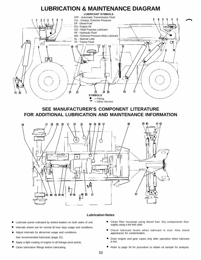
LUBRICATION & MAINTENANCE DIAGRAM LUBRICANT SYMBOLSATF - Automatic Transmission FluidCG - Grease, Extreme PressureDF - Diesel FuelEO - Engine OilGO - Multi Purpose LubricantHF - Hydraulic FluidMG - Extreme Pressure Moly LubricantSL - Special LubeTF - Tractor Fluid
SEE MANUFACTURER’S COMPONENT LITERATUREFOR ADDITIONAL LUBRICATION AND MAINTENANCE INFORMATION
Lubrication Notes
Lubricate points indicated by dotted leaders on both sides of unit.
Intervals shown are for normal (8 hour day) usage and conditions.
Adjust intervals for abnormal usage and conditions.
See recommended lubricants (page 31).
Apply a light coating of engine to all linkage pivot points.
Clean lubrication fittings before lubricating.
Clean filter housings using diesel fuel. Dry components thor-oughly using a lint free cloth.
Check lubricant levels when lubricant is cool. Also checkappearance for contamination.
Drain engine and gear cases only after operation when lubricantis hot.
Refer to page 34 for procedure to obtain oil sample for analysis.
l
l
l
l
l
l
l
l
l
32
SYMBOLS = Fitting = Other Service
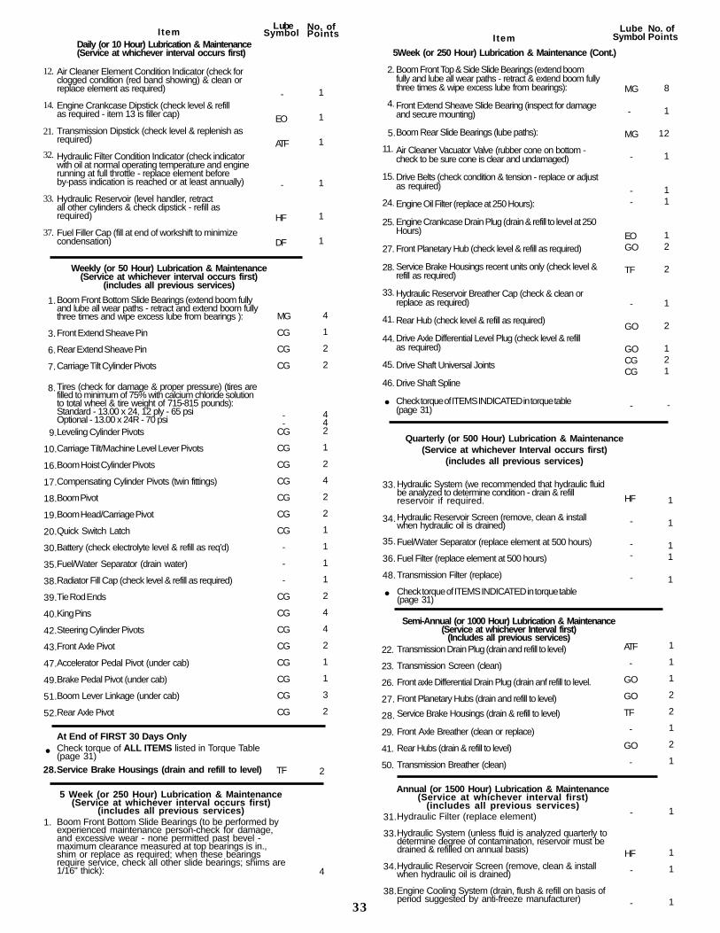
Air Cleaner Element Condition Indicator (check forclogged condition (red band showing) & clean orreplace element as required)
Engine Crankcase Dipstick (check level & refillas required - item 13 is filler cap)
Transmission Dipstick (check level & replenish asrequired)
Hydraulic Filter Condition Indicator (check indicatorwith oil at normal operating temperature and enginerunning at full throttle - replace element beforeby-pass indication is reached or at least annually)
Hydraulic Reservoir (level handler, retractall other cylinders & check dipstick - refill asrequired)
Fuel Filler Cap (fill at end of workshift to minimizecondensation)
Boom Front Bottom Slide Bearings (extend boom fullyand lube all wear paths - retract and extend boom fullythree times and wipe excess lube from bearings ):
Front Extend Sheave Pin
Rear Extend Sheave Pin
Carriage Tilt Cylinder Pivots
Tires (check for damage & proper pressure) (tires arefilled to minimum of 75% with calcium chloride solutionto total wheel & tire weight of 715-815 pounds):Standard - 13.00 x 24, 12 ply - 65 psiOptional - 13.00 x 24R - 70 psiLeveling Cylinder Pivots
Carriage Tilt/Machine Level Lever Pivots
Boom Hoist Cylinder Pivots
Compensating Cylinder Pivots (twin fittings)
Boom Pivot
Boom Head/Carriage Pivot
Quick Switch Latch
Battery (check electrolyte level & refill as req’d)
Fuel/Water Separator (drain water)
Radiator Fill Cap (check level & refill as required)
Tie Rod Ends
King Pins
Steering Cylinder Pivots
Front Axle Pivot
Accelerator Pedal Pivot (under cab)
Brake Pedal Pivot (under cab)
Boom Lever Linkage (under cab)
Rear Axle Pivot
At End of FIRST 30 Days OnlyCheck torque of ALL ITEMS listed in Torque Table(page 31)Service Brake Housings (drain and refill to level)
Boom Front Bottom Slide Bearings (to be performed byexperienced maintenance person-check for damage,and excessive wear - none permitted past bevel -maximum clearance measured at top bearings is in.,shim or replace as required; when these bearingsrequire service, check all other slide bearings; shims are1/16" thick):
Boom Front Top & Side Slide Bearings (extend boomfully and lube all wear paths - retract & extend boom fullythree times & wipe excess lube from bearings):
Front Extend Sheave Slide Bearing (inspect for damageand secure mounting)
Boom Rear Slide Bearings (lube paths):
Air Cleaner Vacuator Valve (rubber cone on bottom -check to be sure cone is clear and undamaged)
Drive Belts (check condition & tension - replace or adjustas required)
Engine Oil Filter (replace at 250 Hours):
Engine Crankcase Drain Plug (drain & refill to level at 250Hours)
Front Planetary Hub (check level & refill as required)
Service Brake Housings recent units only (check level &refill as required)
Hydraulic Reservoir Breather Cap (check & clean orreplace as required)
Rear Hub (check level & refill as required)
Drive Axle Differential Level Plug (check level & refillas required)
Drive Shaft Universal Joints
Drive Shaft Spline
Check torque of ITEMS INDICATED in torque table(page 31)
Hydraulic System (we recommended that hydraulic fluidbe analyzed to determine condition - drain & refillreservoir if required.
Hydraulic Reservoir Screen (remove, clean & installwhen hydraulic oil is drained)
Fuel/Water Separator (replace element at 500 hours)
Fuel Filter (replace element at 500 hours)
Transmission Filter (replace)
Check torque of ITEMS INDICATED in torque table(page 31)
Transmission Drain Plug (drain and refill to level)
Transmission Screen (clean)
Front axle Differential Drain Plug (drain anf refill to level.
Front Planetary Hubs (drain and refill to level)
Service Brake Housings (drain & refill to level)
Front Axle Breather (clean or replace)
Rear Hubs (drain & refill to level)
Transmission Breather (clean)
Hydraulic Filter (replace element)
Hydraulic System (unless fluid is analyzed quarterly todetermine degree of contamination, reservoir must bedrained & refilled on annual basis)
Hydraulic Reservoir Screen (remove, clean & installwhen hydraulic oil is drained)
Engine Cooling System (drain, flush & refill on basis ofperiod suggested by anti-freeze manufacturer)
12.
14.
21.
32.
33.
37.
28.
l
33
l
33.
34.
35.
36.
48.
l
22.
23.
26.
27.
28.
29.
41.
50.
LubeSymbolI tem
Daily (or 10 Hour) Lubrication & Maintenance(Service at whichever interval occurs first)
No. ofPoints
-
EO
ATF
-
HF
DF
1
1
1
1
1
1
1.
3.
6.
7.
8.
9.
10.
16.
17.
18.
19.
20.
30.
35.
38.
39.
40.
42.
43.
47.
49.
51.
52.
Weekly (or 50 Hour) Lubrication & Maintenance(Service at whichever interval occurs first)
(includes all previous services)
MG
CG
CG
CG
--
CG
CG
CG
CG
CG
CG
CG
-
-
-
CG
CG
CG
CG
CG
CG
CG
CG
TF 2
4
1
2
2
442
1
2
4
2
2
1
1
1
1
2
4
4
2
1
1
3
2
5 Week (or 250 Hour) Lubrication & Maintenance(Service at whichever interval occurs first)
(includes all previous services)
4
5Week (or 250 Hour) Lubrication & Maintenance (Cont.)
I temLube
Symbol
2.
4.
5.
11.
15.
24.
25.
27.
28.
33.
41.
44.
45.
46.
No. ofPoints
Quarterly (or 500 Hour) Lubrication & Maintenance(Service at whichever Interval occurs first)
(includes all previous services)
MG
-
MG
-
--
EOGO
TF
-
GO
GOCGCG
-
8
1
12
1
1 1
1 2
2
1
2
1 2 1
-
HF
-
--
-
1
1
11
1
Semi-Annual (or 1000 Hour) Lubrication & Maintenance(Service at whichever Interval first)
(Includes all previous services)ATF
-
GO
GO
TF
-
GO
-
1
1
1
2
2
1
2
1
Annual (or 1500 Hour) Lubrication & Maintenance(Service at whichever interval first)
(includes all previous services)31.
33.
34.
38.
1.-
HF
-
-
1
1
1
1
Operate unit until hydraulic oil reaches normalopera t ing tempera tu re .
Apply parking brake and observe hydraulic filterby-pass indicator with engine running at fullthrot t le. Replace f i l ter elements i f necessary.
Obtain a container to receive waste oil and aCLEAN container to receive oi l sample.
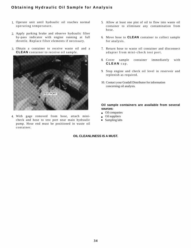
With gage removed from hose, attach mini-check and hose to test port near main hydraulicpump. Hose end must be positioned in waste oilconta iner.
Allow at least one pint of oil to flow into waste oilcontainer to eliminate any contamination fromhose.
Move hose to CLEAN container to collect samplefor analysis.
Return hose to waste oil container and disconnectadap te r f r om m in i - check t es t po r t .
Cover sample container immediately withC L E A N c a p .
Stop engine and check oil level in reservoir andreplenish as required.
Contact your Gradall Distributor for informationconcerning oil analysis.
Oil sample containers are available from severalsources:
Oil companiesOil suppliersSampling labs
O b t a i n i n g H y d r a u l i c O i l S a m p l e f o r A n a l y s i s
1.
2.
3.
5.
6.
7.
8.
9.
10.
4.l
ll
34
OIL CLEANLINESS IS A MUST.
TEST PORT
The following procedure assumes that han-dler cannot be moved under its own power.
The safest way to move a disabled handler is to use atow trucK of sufficient capacity to raise front wheelsclear of ground - OR - use a ramp/flatbed vehicle ofsuff ic ient capac i ty.
The next safest is pushing the unit and least safe istowing the unit.
Whichever method is used, certain preliminary stepsmust be taken. Perform following procedure asappropr ia te for method se lec ted.
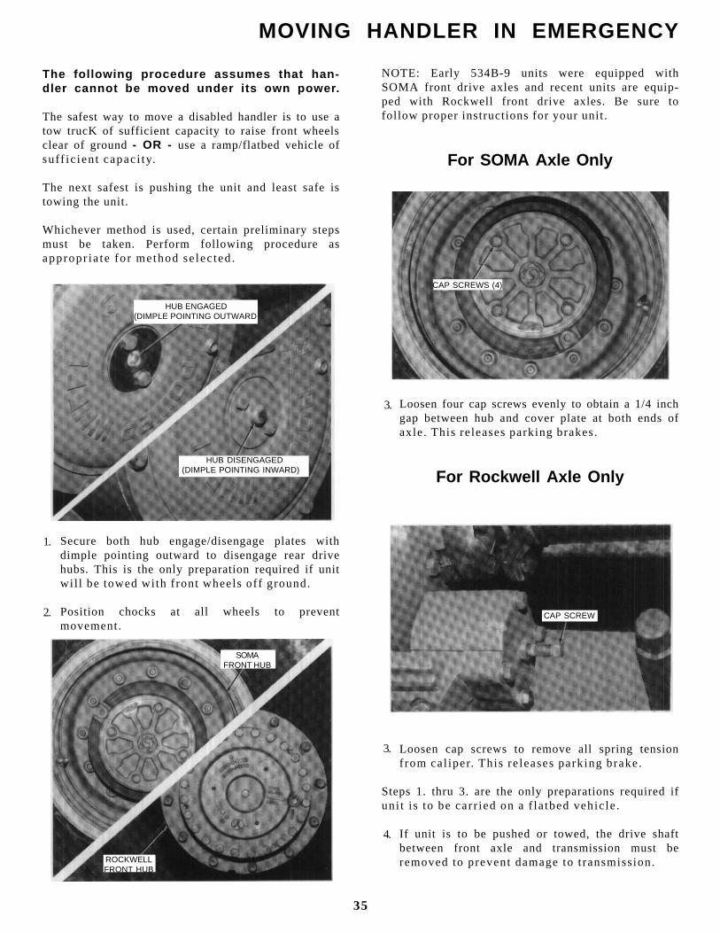
Secure both hub engage/disengage plates withdimple pointing outward to disengage rear drivehubs. This is the only preparation required if unitwi l l be towed with f ront wheels of f ground.
Position chocks at all wheels to preventmovement.
NOTE: Early 534B-9 units were equipped withSOMA front drive axles and recent units are equip-ped with Rockwell front drive axles. Be sure tofol low proper instructions for your unit.
For SOMA Axle Only
Loosen four cap screws evenly to obtain a 1/4 inchgap between hub and cover plate at both ends ofaxle. This releases parking brakes.
For Rockwell Axle Only
Loosen cap screws to remove all spring tensionfrom cal iper. This re leases park ing brake.
Steps 1. thru 3. are the only preparations required ifuni t is to be carr ied on a f la tbed vehic le.
If unit is to be pushed or towed, the drive shaftbetween front axle and transmission must beremoved to prevent damage to t ransmission.
MOVING HANDLER IN EMERGENCY
1.
2.
HUB ENGAGED(DIMPLE POINTING OUTWARD
HUB DISENGAGED(DIMPLE POINTING INWARD)
HUB ENGAGED(DIMPLE POINTING OUTWARD
SOMAFRONT HUB
ROCKWELLFRONT HUB
CAP SCREWS (4)
CAP SCREW
3.
3.
4.
35

If handler is to be pushed, secure unit to pushingvehicle to prevent handler from rolling on its ownwith NO BRAKES.
If handler is to be towed, use a rigid connection toprevent rear end collision with handler having NOBRAKES.
TRAVEL SLOWLY TO MAINTAIN CONTROL.
Pushing or towing handler with enginestopped, accumulator drained and parkingbrake released can be dangerous becausethere are NO BRAKES.
Although manual steering is possible with-out power assist, STEERING WILL BESLOW AND DIFFICULT.
PUSH OR TOW SLOWLY TO MAINTAINCONTROL.
5.
36

HAND SIGNALSStandard Signals - When handler work conditionsrequire hand signals, they shall be provided orposted conspicuously for the use of both signalmanand operator. No handler motions shall be madeunless signals are clearly understood by bothsignalman and operator.
Special Signals - When signals for auxiliaryequipment functions or conditions not covered arerequired, they shall be agreed upon in advance bythe operator and signalman.
Instructions - When it is desired to give instructionsto the operator other than provided by theestablished signal system, all handler motions shallfirst be stopped.
EMERGENCY STOP - With botharms extended laterally, hands opendownward, move arms back and forth.
EXTEND TELESCOPIC BOOM -With both hands clenched, pointthumbs outward.
MOVE LOAD OUT HORIZONTALLYWith either arm extended, handraised and open toward direction ofmovement, move hand in direction ofrequired movement.
CLOSE BUCKET - Hold one handclosed and stationary. Rotate otherhand in small vertical circle withforefinger pointing horizontally atclosed hand.
STOP - With either arm extendedlaterally, hand open downward,move arm back and forth.
RETRACT TELESCOPIC BOOM -With both hands clenched, pointthumbs inward.
MOVE LOAD IN HORIZONTALLY -With either arm extended, handraised and open toward direction ofmovement, move hand in direction ofrequired movement.
OPEN BUCKET - Hold one handopen and stationary. Rotate otherhand in small vertical circle withforefinger pointing horizontally atopen hand.
STOP ENGINE - Draw thumb orforefinger across throat.
RAISE BOOM - With either armextended horizontally, fingersclosed, point thumb upward.
RAISE LOAD VERTICALLY - Witheither forearm vertical, forefingerpointing up, move hand in smallhorizontal circle.
TILT FORKS UP - With one arm heldat side, extend other arm upward atabout 45 .
MOVE SLOWLY - Place one handmotionless in front of hand givingmotion signal. (Raise load slowly isshown.)
LOWER BOOM - With either armextended horizontally, fingersclosed, point thumb downward.
LOWER LOAD VERTICALLY - Witheither arm extended downward,forefinger pointing down, move handin small horizontal circle.
TILT FORKS DOWN - With one armheld at side, extend other armdownward at about 45 °
THIS FAR TO GO - With hands raisedand open inward, move handslaterally, indicating distance to go.