Embed Size (px)
Citation preview

W S K ~ P Z L - S W I D N I K ~ S . A . s-- 4. Al. Lotnik6w Polskieh 1,21-045 Swidnik, PO-
SAILPLANE FLIGHT MANUAL
i
Model: P& - 5 "SMYK"
O Serial NO: 17.'i I .002
Registration:
Document No: PW-5/IWLllU/97
To be mandatory for sailplanes from S/N 17.07.010.
Date of issue: March 17th. 1997.
In Polish original pages identified by "Appr." are approved by Polish aviation authority: . .
0 General Inspectorate of Civil Aviation Civil Air& Inspection Board
Seal:
Original date of approval:
I This Manual should always be on board of the sailplane 1 This sailplane is to be operated in compliance with information and limitations
A contained herein.
<J The English translation bas been made to the best of our knowledge and belief, but in case of uncertainty the Polish original is authoritative.
The English translation has been made by Wieslaw Stafiej. -,
PW-5 " S ~ " S a i l p l a n e F l i g h t Manual
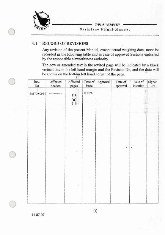
0.1 RECORD OF REVISIONS
Any revision of the present Manual, except actual weighing data, must be recorded in the following table and in case of approved Sections endorsed by the responsible airworthiness authority.
The new or amended text in the revised page will be indicated by a black vertical line in tho left hand margin and the Revision No, and tho date will be shown on the bottdm left hand comer of the page.
i

I I : , ,
!? , . 1 i' . . . PW-5 "SIMYIP'
; - .:Sailpl%ne Fl ight Manual , .
0.2 LIST OF EFFECTIVE PAGES
Section Pagc Datc of issue Scctio~l
I I I o 0) 11.07.97 5
(ii) 11.07.97 (iii) 17.03.97
(ii)

PW-5 "SEPzK"
7 Sailplane Flight Manual
0.3 TABLE OF CONTENTS
Section
GENERAL (a nonapproved section)
LIMITATIONS (an appmved section)
EMERGENCI'PROCEDURES (an appmved section)
N O W PROCEDURES (an approved section)
PERFORMANCE (a partly approved section) JVEJGBTAND BALANCE (a non-approved section)
SAILPLANE AND SYSTEM DIBCRIFTION (a non-approved section)
SAILPLANE XI4NDLmTG, CARE AND MAINTENANCE (a non-approved section)
SUPPLEMENTS
(iii)

... I.:: .
PW-5 "SMYK"
!> S a i l p l a n e F l ight M a n u a l
SECTION 1
G E N E R A L
0 1.1 INTRODUCTION
1.2 CERTIFICATION BASIS
1.3 WARNINGS, CAUTIONS AND NOTES
1.4 DESCRIPTIVE DATA
1.5 THREE-MEW DRAWING
1.6 ABBREVIATIONS

PW-5 "SMYK" - ..- :1 S a i l p l a n e F l i gh t Manua l -
1.1 INTRODUCTION
This Flight Manual has been prepared to provide pilots and instructors with the information for safe and efficient owration of PW-5 "Smyk" sailplane.
This Manual includes the material required by Joint Ainvorthiness Requirements JAR-22 and supplementary information supplied by the sailplane manufacturer.
0 1.2 CERTIFICATION BASIS
This type of sailplane has been approved by Civil Aircraft Inspection Board in accordance with Joint Airworthiness Requirements JAR-22 - issue of May 7th, 1987 with Change 4 and amendments: 2219011. 2219111.
The Type Certificate No BG194 has been issued on March 10th 1994, category of airworthiness "W' (utility).
1.3 WARNINGS, CAUTIONS, NOTES
',tl WARNING: MEANS THAT THE NON-OBSERVATION OF THE CORRESPONDING PROCEDURE LEADS TO AN IMMEDIATE OR IMPORTANT D.EGRADATION OF THE FLIGHT SAFETY
# ~ , . . . ,,
C) CAUTION: . , I
:', ' '!
MEANS THAT THE NON-OBSERVATION OF THE CORRESPONDING PROCEDURE L E m S TO A MINOR OR TO A MORE OR LESS LONG TERM DEGRADATION OF THE'FLIGHT SAFETY
NOTE:
Draws the attention on any special item not directly relstcd to safety, but which is important or unusual,

EW-5 "SMYIC' r ,
,/3 S a i l p l a n i Fl ight hhanual
1.4 DESCRIPTIVE DATA
SAILPLANE DESCRIPTION
PW-5 "Smyk" is the singleseat sailplane with the cantilever mid-wing and standard tailplane arrangement. The structure is all glass-epoxy composite.
The wings of trapeze"contour with bow-shaped ends. The wings are of monospar structure wjth sandwich shells.
The plate air brake extended on the upper wing surface only. ..
The fuselage shells are of mono~oque~structure, stiff+ ..... with frames.
Rudder is fabric covered.
The cockpit is equipped with in flight adjustable pedals and back rest adjustable on ground. The canopy opens forwards.
The fixed undercamage contains of the main whcel with shock absorber and drum brake, fiont wheel and tail skid with small wheel.
Two take-off hooks are installed (nose hook for aerotowing and C.G. hook for winch-launching).
BASIC DATA . . . wing span ................................................................. 13.44 m length ....................... .. ........................................... 6.22 m height ......................................................................... 1.86 m
2 wingarea ................................................................ 1 0 m aspect ratio ................................................................. 17.8
2 wing loading ........................................................ 29.5 kglm Mean Standard Chord. 98 m

. ..*w-5 "SMYIC'
n Sai lp la%@ F l i g h t M a n u a l
1.5 THREE-VIEW DRAWING
PW-5 "Smyk" sailplane Fig. 1 - 1
. , .!,,
PW-5 " s m ' .? Sa i lp l ane F l igh t Manual
1.6 ABBREVIATIONS
CAS - calibrated airspeed means indicated airspeed of a sailplane. corrected for position (due to position of pressure ports on sailplane) and instrument error. Calibrated airspeed is equal to true airspeed in standard atmosphere at sea level.
C.G. - centre of gravity.
daN - decanewton.
h - I~our.
IAS - indicated airspeed means the speed of a sailplane as shown on its pitot - static airspeed indicator unconatcd for airspeed indicator system error. In this Manual zero instrument error is assumpt.
m - meter.
ft - feet
kg - kilogram.
kts - h o t s
s - second.
Vsl - mesns the stall speed or the minimum steady flight speed obtained .. . in a specific configuration.
I PW-5 "SMYfC"
1 ! S a i l p l a n e F l i g h t Manual
SECTION 2
0 2.1 INTRODUCTION
2.2 AIRSPEED
2.3 AIRSPEED INDICATOR MARKINGS
2.4 WEIGHT
2.5 CENTRE OF GRAVITY
2.6 APPROVED MANOEUVRES
2.7 MANOEUVRING LOAD FACTORS
2.8 KINDS OF OPERATIONS
2.9 MINIMUM EQUIPMENT
0 2.10 AEROTOW AND WINCH-LAUNCHING
2.11 OTHER LIMITATIONS
2.12 LIMITATIONS PLACARDS

PW-5 "SMYK"
(7 S a i l p l a n e F l i gh t Manua l
2.1 INTRODUCTION
Section 2 includes operating limitations, air speed indicator markings, limitations placards necessary for safe operation of the sailplane. The limitations included in this Section and in Section 9 have been approved by Civil Aircraft Inspection Board.
2.2 . AIRSPEED
0 Airspeed limitations and their operational significance are shown below:
I j speed
VNE 1 Never exceed speed
!
I
, Maximum winch
Yw launchimgspeed Maximum aerotowing
vT 1 speed
I deflection
' VA
kts IAS 115
Manoeuvring speed
Appr. 2.2
I Remarks I
i Do not exceed this speed in /
any operation and do not use / I
VRA / Rough air speed
81
65
I I !
more than li3 of control i
81 Do not exceed this speed I except in smooth air and 1 th& only with caution. i Examples of roughair are:
leewave rotor. thunderclouds, etc.
Do not make full orabrupt controf mAvement above ; this speed, because under I
certain conditions the sailplane may be
overstressed by full control
Do not exceed this speed during winch-lalmching.
81 Do not exceed this speed (CAS / during aemtowing. =RO\

PW-5 "SMYK"
I? Sailplane Flight Manual
2.3 AIR SPEED INDICATOR MARKINGS
Airspeed indicator marldngs and their colour-code significance are shown below:
Appr. 2.3

PW-5 "m' . ,
i' l Sa i lp l ane Fl ight Manual -, ,-
2.4 WEIGHT r
maximum weight ..... .? .................................................... 300 kg maximum fuselage and tailplane weight ........................ 112 kg maximum load in luggage compartment ............................. 5 kg . .
2.5 CENTRE OF GRAVTY Centre of Gravity range for flight:
-front limit 20% of Mean Standard Chord . 23.5 cm aft of root chord leading edge
- rear limit 42% of Mean Standadphord ..:&:+-
41.0 cm aft of root chord leading edge.
The way of C.G. location finding and the C.G. location range fur empty sailplane are described in MAINTENANCE MANUAL.
WARNING:
THE SAILPLANE MAY BE SAFETY OPERATED ONLY WHEN LOADED IN RANGE DEFINED IN SECXION 6 OF THIS MANUAL.
. . . 2.6 APPROVED MANOEUVRES
,.J This sailplane is certified in the Utility Category.
The following manoeuvres are allowed :
- looping,
- stall turn - spinning,
- spiral.
Performing technique and rccommcnded entry speeds are contained in
11 Section 4 of this Manual.
Appr. 2.4

.. PW-5 "GMYIC'
r? Sailplane Flight Manual
2.7. MANOEUVRING LOAD FACTORS
Limit load factors are :
-forVA = 81ktsairspeed +5.3 I -2.65 -for Vm = 1lSkts airspeed +4.0 1 -1.5
2.8 KINDS OF OPERATION
0 - day flying, - cloud flying, - acrobatic manoeuvres (according to item 2.6 ofthis Manual).
2.9 MINIMUM EQUIPMENT
- 4 pieces pilot's belt$ - airspeed indicator (marked per item 2.3 of this Manual), - altimeter, - total energy variometer, - variometer, - magnetic compass, - sideslip and turn indicator, -transceiver. - power supply.
CAUTION: .. . - DURING THE FLIGHT PILOT MUST HAVE BACK PARACHUTE AlTACHED.
Appr. 2.5

. . .XI i . ,.
PW-5 "SMYK"
!- > Sa i lp l ane Fl ight Manual
2.10 AEROTOW AND WINCH - LAUNCHING
AEROTOW
The hook for aerotowing (nose hook) is located before the front wheel.
- maximum aemtowing airspeed V ~ = 8 l kts (CAS = 80 lits)
- maximum force damaging the towing cable or safety link 700 daN
-minimum towing cable length 20 m
WARNING: THE AEITOWING WHEN USING THE C.G. HOOK IS NOT PERMITTED.
WINCH-LAUNCHING
The hook for winch-launching (C.G. hook with automatic release) is located before the main wheel on the lei? side of fuselage.
CAUTION:
THE WINCH-LAUNCHING WHEN USING THE FRONT HOOK IS NOT PERMITTED. . .
.J - maximum winch-launching speed Vw=65 kts -maximum force damaging the cable or safety link 700 daW
!:it
2.11 OTHER LIMITATIONS
1) Flying in known icing conditions is not permitted. 2) Night flying is net permitted. -. 3) Aembatio manoe&@s in rough air are prohibired. 4) The pilots of body + parachute weight of below 60 kg must have the
h n t limit location of the back rest. , .
. -. 5) The flights on the altitude of above 16400 ft are prohibited. j
PW+smmK" A Sa i lp l ade Fli-ght Manual
, ,
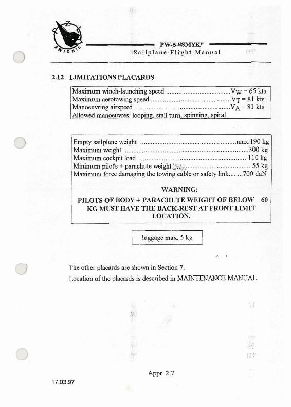
2.12 LIMITATIONS PLACARDS
Maximum winch-launching speed ................... .- ............. Vw = 65 kts Maximum aemtowing speed ............................................... V = 81 kts
........................................................ Manoeuvring airspeed V = 81 kts Mowed manoeuvres: looping, stall turn spinning, spiral
Empty sailplane weight ....................................................... maxl90 kg Maximum weight ....................................................................... 300 kg
............................................................. Maximum cockpit load 110 kg ..... Minimum pilofs + p q h u t e weight.:=$ ...................... ......... 55 kg
........ Maximum force damaging the towing cable or safety link 700 daN
WARNING: PILOTS OF BODY + PARACHUTE WEIGHT OF BELOW' 60
KG MUST HAVE THE BACK-REST AT FRONT LIMIT LOCATION.
The other placards are shom~ in Section 7.
Location of the placards is described in MAINTENANCE MANUAL.
Appr. 2.7

NCP FRO-

PW-5 "SMYK" -."--..+-
-\ Sai lp lane Fl ight Manual i,.--- . . . - - . - A -
SECTION 4
N O R M A L P R O C E D U R E S
4.2 RIGGING AND DE-RIGGING .&- . . . -. '*
4.3 PRE-FLIGHT INSPECTION
4.4 INSPECTION BEFORE TAKE-OFF
4.5 NORMAL PROCEDURES AND RECOMMENDED SPEEDS
4.5.1 PROCEDURES BEFORE TAKE-OFF
4 .52 TAKE-OFF
4.5.3 FLIGHT
4.5.4 APPROACH
4.5.5 LANDING 0 4.5.6 FLIGHT RAIN
4.5.7 AEROBATICS
4.6 PROCEDURES AFTER FLIGHTS

+,L. PW-5 "SMYIC' S a ~ l p l a n e F l igh t Manual
4.1 INTRODUCTION
Section 4 provides the procedures of n o d sailplane operation.
The normal procedures associated with additional equipment can be found in Section 9.
4.2 RIGGING AND DE-RIGGING
A) Rigging team: 2 persons (or 3 persons without the rigging jigs). B) Rigging jigs: fuselage support, wing tip support (of about 1.2 m
height). .. C) Sequence of rigging procedures:
1. clean and grease all the assembling fittings, bolts and conbol system connections,
2. put the fuselage on the support (in case no support is in disposition one person hol& the fuselage), open the canopy, put the'aubrake cockpit lever backwards, open the inspection hole on h e fuselage,
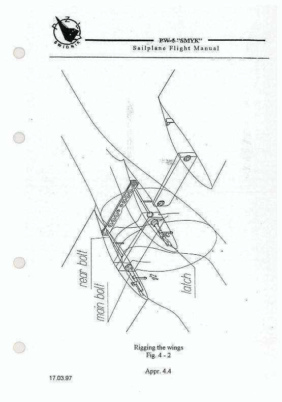
3. assemble the right-hand wing first. Insert the spar end into the fuselage. Fit together the wing and fuselage fittings. insert the right-hand main bolt to 112" location ( bolt lever locate in the grip) then insert the left-hand main bolt into "ID" location too (as above) - insert the right-hand rear bolt till to stop-(see pig. 4-2), .. .
1 CAUTION:
THE BOLTS SHALL BE INSERTED BY HAND ONLY, NO TOOL ALLOWED. IN CASE OF JAMMING (EXCESSIVE DRAG) BREAK THE RIGGING AND CHECK THE BOLTS FOR COKXECT CLEANING.
4. support the wing tip ( in case of having no support one person should hold the wing),
5. rigging of the left-hand wing: insert the spar end into the fuselags. fit together the wing and fuselage fittings, ulsert the rear bolt till to stop, insert the left-hand main bolt till to securing it with the latch- then insert the right-hand main bolt in the same manner,
6. connect the control systems of aileron and air brake (see Fig. 4 -1 ). Appr. 4.2
17.03.97

PW-5 "SMYIC' Sa i lp l ane F l igh t Manual
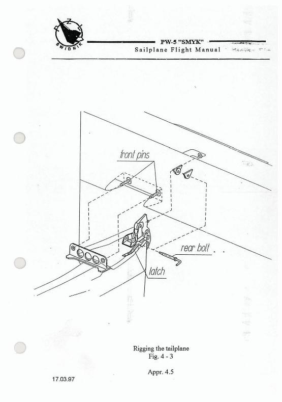
7. rigging of the tailplane: deflect the rudder till to stop, fit the tailplane to fuselage (the stabiliser h n t pins must engage the fuselage fittings), insert the rear bolt (placing the latch in lower position) till to securing with the latch. The elevator control circuit is connected aut&matically, (see Fig. 4 -3 ),
8. check securing of the main bolts of wings and rear bolt of tailplane and connection of control systems, close the inspection hole on the fuselage.
De-rigging requires the inverted sequence.
A) The connected and secured end
B) The end disconnected
Connection of control system of aileron and air brake with"disconnectab1e ends. Fig. 4 - 1
Appr. 4.3 17.03.97
p=2sMYK" s a i l p l a n e Pl ight Manual
Rigging the wings Fig. 4 - 2
Appr. 4.4
PW-S!'SMYIE' ~~ . . - .. - . f 3 Sailplane Fl ight Manual . .-:.-
. ,
Rigging the tailplane Fig. 4 - 3
.e PW-5 "SMYZC'
I Sa i lp l ane Fl ight Manual
4.3 PRE - FLIGHT INSPECTION
NOTE:
Before the flight the validity of Airwortbhess Certificate and the updating of periodic inspections should be checked.
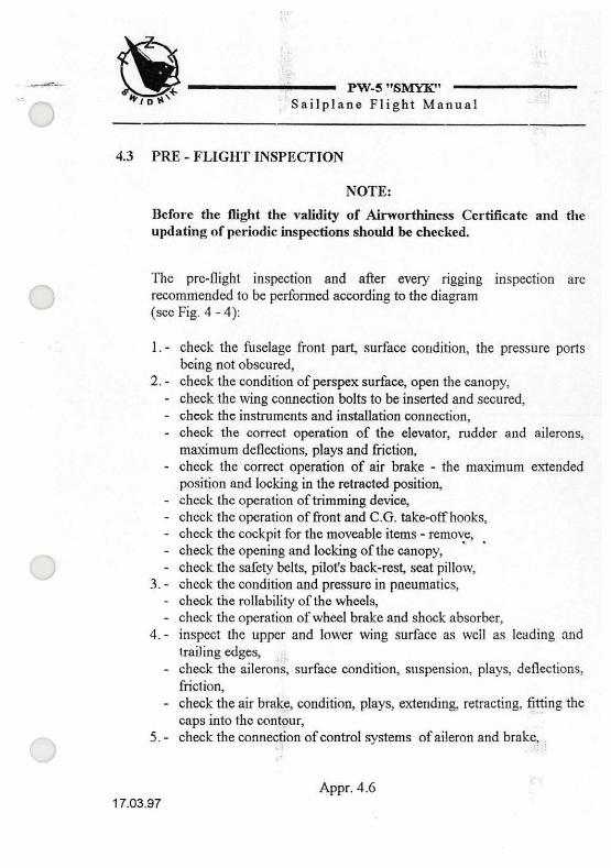
The pre-flight inspection and after every rigging inspection are recommended to be performed according to the diagram (see Fig. 4 - 4):
1. - check the fuselage front part, surface condition, the pressure ports being not obscured,
2. - check the condition of perspex surface, open the canopy, - check the wing co~ect ion bolts to be inserted and secured, - check the instruments and installation connection, - check the correct operation of the elevator, rudder and ailerons,
maximum deflections, plays and friction, - check the correct operation of air brake - the maximum extended
position and locking in the retracted position, - check the operation of trimming device, - check the operation of fiont and C.G. take-off hooks, - check the cockpit for the moveable items - remove, . - check the opening and locking of the canopy,
.. - check the safety belts, pilot's back-rest, seat pillow,
3. - check the condition and pressure in pneumatics, - check the rollability of the wheels, - check the operation of wheel brake and shock absorber,
4. - inspect the upper and lonver wing surface as well as leading and hailing edges, ,
- check the ailerons, surface condition, sospension, plays, deflections, friction,
- check the air brake, condition, plays, extending, retracting, fitting the caps into the contour,
5. - check the connection of control systems of aileron and brake, .. ,

PW-5 "SMYK" Sailplane Flight Manual
Pre - flight inspection Fig. 4 - 4

m - 5 j'SMYfC1
f 7 Sai lp lane ~ l i g b t Manual-&.
6. - check the hselage rear part, especially bottom part and tail skid, - check the iin, surface. condition, - check the rndder for fabric covering damages, upper hinge and cable
fitting securing, 7. - check the tailplane, fitting, scouring, surface condition,
- check the elevator deflections, plays, friction, 8.- asinitem4.
44 INSPECTION BEFORE TAKE-OFF
- check the $stening bolts to be in position and secured, - check the tailplane for the correct rigging and securing, - open the inspection hole and check the aileron and aG brake control
system ends for correct connection and securing. - check the wrrcct operation of control surfaces and air broke namely
without jamming, excessive play and that they have the full movements.
4.5 NORMAL PROCEDURES AND RECOMMENDED SPEEDS
4.5.1 PROCEDURES BEFORE TAKE-OFF
- check and put on the parachute, - adjust the pilots back-resf - take placc in the cockpit, - fasten and tighten the belts,
3 - adjustthe pedals, - make the fill movements of wntrol surfaces, pull the towing cable
release handle, extend and retract the air brake, - check the transceiver operation, - check the altimeter setting, - closc and lock canopy.
3
Appr. 4.8

4.5.2 TAKE-OFF
A) AEROTOWING Before takeoff put the mmming devim handle into 1-2 position for the light pilot and up to 5-6 position for the hemy pilot. Roll on the main wheel. The controlling behaviours in towed flight are the typical ones. The sailplane can be trimmed in the whole airspeed range in towed flight.
0 The flying under the towing airplane downwash is not recommended since the towing cable rubs the fuselage h n t part.
Recommended aemtowing ... airspeeds: - at climbing 60 kts -at cross-country towing 81 kts
Before takeoff put the trimming device handle into position 1 for the light pilot up to 5-6 position for the heavy pilot. Due to the hook location it is recommended the launching cable positioil at the left-hand side of the sailplane. If however the cable is situated clearly at the right-hand side of 'the sailplane it should not he positioned on the left side of the h n t wheel. During the ground run the stick should not be pulled excessively to avoid the tail skid impact onto the ground. Roll on the main wheel. During the steep climb the stick forces are of small value. The best launching airs* is 49 -54 kts.
RELEASING
The sailplane is equipped with the self-releasing hook.
Two releasing techniques exist: 1) before the intended releasing release the stick tojower the cable
tension then pull the releasing handle in the cockpit,. 2) befnre the intended releasing hold the stick in position till the self-
releasing occurs. After releasing recover immediately the glide and check the cable releasing pulling the control handle.
Appr. 4.9
PW-5 ''SMYK" R; ' Yailplane Fl ight Manual
4.5.3 FLIGHT
CIRCLING
The circling airspeed, depending on the bank angle and sailplane weight ranges 43 -46 kts. The bank reversal 45'/45O requires 3.5 seconds.
SIDE SLIP
>I The sideslip should be performed at the airspeed of 49 kts or higher. Up to 20' bank the sailplane allows to retain the heading. For the greater bank the sailplane turns. With air brake retracted as well as with extended the sideslip is a typical one. The airspeed indicator records in sideslip are not valid.
AIR BRAKE OPERATION
For the airbrake full extended the sailplane ratio in approach is 6.5. The diving at 45" in respcct to the horizon with air brake fnll extended does not exceed 115 kts airspeed. The extending or retracting of the air brake creates no pitch. The air brake may be extended in the whole airspeed range. The retraction requires the airspeed of below 81 kts.
NOTE:
When extending the airbrake a t the airspeed above 92 kts the considerable negative vertical acceleration appears. Therefore the air brake should be extended gently. The pilot should be tightened with the belts
4.5.4 APPROACH
Recommended approach airspeed is 51 kts,, The approach angle should be adjusted by means of air brgke.
4.5.5 LANDING
Touch ground with the main wheel. Avoid the tail skid ground impact. Ground run should employ the front wheel to allow for direction retaining and efficient braking.
Appr. 4.10

PW-5 " s m ' Sa i lp l ane P l i g h t Manual
4.5.6 FLIGHT IN RAIN
No abnormal control characteristics when flying in rain appear. No significant increase of stalling speed observed.
4.5.7 AEROBATICS
Before the initiation of the manoeuvres the sailplane should be trimmed for about 70 kts airspeed. Check the air brake to be locked and check the absence of moveable items in the cockpit. Manoeuvres are performed in the typical way. The recommended entry (recovery) speeds and load factors gained are
s~-.-. listed below:
I Manoeuvre I entry speed (IAS) kts j load factors I coping 1 92 97 to 97 3.4 g 1
stall turn 3.2 g
spinning 81 (recovery) 4.0 g
spiral 65 3.5 - 4.0 g
SAILPLANE BEHAVIOURS IN SPINNING
pilot with light parachute
aileron arbitrary deflection
longitudinal exist oscillations considerable
angle in respect 40 - 50 deg. to the horizon t
neutral or only towards
exist I not exist
delay in I no more than 314 recove.ry of turn
The recovery is typical one (see item 3.5).
Appr. 4.1 1

_ PW-5 " S Y I C '
i '\ Sailplane Flight Manual
4.6 PROCEDURES ABTER FLIGHTS
- switch-off the electrical devices, -drain, if necessary, the ducts of total and static pressure installations (acc. to MAINTENANCE MANUAL).
-clean the pilot's cockpit and the whole sailplane, -perform the inspection same as the pre-flight one.

PW-5 "SMYK" - /7 S a i l p l a n e F l i g h t M a n u a l
P E R F O R M A N C E
0 5.1 INTRODUCTION
. . . :;>it ~. . .. . . 5.2 APPROVED DATA
. . ..-
5.2.1 AIRSPEED INDICATOR SYSTEM CALIBRATION 5.2.2 STALL SPEED (US)
5.3 NON-APPROVED FURTHER INFORMATION 5.3.1 DEMONSTRATED CROSSWIND PERFORMANCE 5.3.2 FLIGHT POLAR
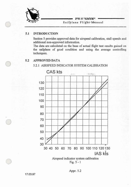
INTRODUCTION
Section 5 provides approved data for airspeed calibration, stall speeds and additional non-approved information. The data are calculated on the base of actual flight test results gained on the sailplane of g o d condition and using the average controlling techniques.
APPROVED DATA
5.2.1 AIRSPEED INDICATOR SYSTEM CALIBRATION
30 40 50 60 70 80 90 100 110 120130
IAS kis Airspeed indicator system calibration
Fig. 5 - 1
Appr. 5.2

- PW-5 "SMYIC' '%$-iepIBhe'Flight M a n u a l
5.2.2 STALL SPEEDS (IAS)
SAILPLANE WITH HEAVY PILOT
The sailplane with heavy pilot (above 90 kg) does not stall in straight flight with air brake extended as well as retracted.
The flight with the stick pulled full is possible with the minimum airspeed of about 30 - 35 kts. With the air brake extended the minimum airspeed ranges about 33 - 38 kts.
1 When circling with 45" bank the sailplane does not stall zither. The minimum airspeed ranges about 36 - 38 kts. With the air brake extended the minimum airspeed ranges about 39 - 41 kts.
~~~ .. ~. .. .
SAILPLANE WITH MEAN OR LIGHT PILOT
The sailplane with mean or light pilot (55-90 kg) stalls in straight flight gently and it is possible to retain the lateral balance.
The stall warning is mild. When stalled the sailplane drops doivn very gently and symmetrically. When pulling the stick more no tendency to wing dropping appears. The stalling speed ranges about 26-3 1 kts. With
the air brake extended the stalling speed ranges about 30-36 kts.
When circling with 45' bank as the critical airspeed is gained the sailplane automatically recovers the wings to level position or gently banks towards the hun. The slight releasing of the stick or the aileron deflection
i associated with the stick releasing results the transition to the normal flight without the tendency to spimling. The stalling speed ranges about 30- 36 kts. With the air brake extended the stalling speed ranges about 36-39 kts.
The altitude loss during recovery is not more than 98 ft.
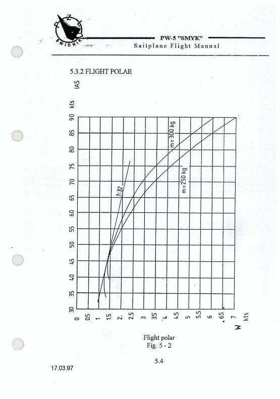
5.3 NON-APPROVED FURTHER INFORhlATION 3
5.3.1 DEMONSTRATED CROSSWIND PERFORMANCE
The demonstrated crosswind component at take-off and landing is 12 kts.
During the take-off or landing ground run 011 two wheels the sailplane is practically non-sensitive to the crosswind action.
Appr. 5.3
-@- .I PW-5 "BMYK"
k,.,c\ ,-. ... I?
S a i l p l a n e F l i g h t Manual
5.3.2 FLIGHT POLAR V) 9
Right polar Fig. 5 - 2

PW-5 "SI\IYIC' Sa i lp lane Fl ight Manual
SECTION 6
WEIGHT A N D B A L A N C E
6.1 INTRODUCTION
, 6.2 PERMITTED PAYLOAD RANGE AND WEIGHT AND BALANCE RECORD

PW-5 "SMYIC' - 1 ' 7 Sa i lp l ane Fl ight Manual
6.1 INTRODUCTION
This Section contains the payload range within which the sailplane may be safely operated.
The weighing and C.G. location calculation procedure as well as the range of weight and C.G. looations of empty sailplane are contained in MAINTENANCE MANUAL.
0 Comprehensive list of all equipment available for this sailplane and the installed equipment during the weighting of the sailplane is contained in MAINTENANCE MANUAL.
6.2 PERMITTED PAYLQAD RANGE AND WEIGHT AND BALANCE RECORD PERMITTED PAYLOAD RANGE Maximum cockpit load (pilot + parachute + luggage) .......... 1 10 kg Minimum pilors weight with parachute ............................... 55 kg
CAUTION: PILOTS OF THE BODY+PARACHUTE WEIGHT BELOW - - - - - - - - - -
60 KG MUST HAVE THE BACK-REST LOCATED IN LIMIT FRONT POSITION

PW-5 "SMYK" Sai lp l 'ane F l i g h t M a n u a l
WEIGHT AND BALANCE RECORD

PW-5 "SMYK'?
(-3 Sai lp lane Fl ight Manual -. -
SECTION 7
S A I L P L A N E A N D S Y S T E M S D E S C R I P T I O N
..j
7.2 COCKPIT DEVICES
7.3 LUGGAGE COMPARTMENT
7.4 INFORMATION PLACARDS IN COCKPIT
Pw-5 "SMYIC'
A Sai lp lane Flight Manual
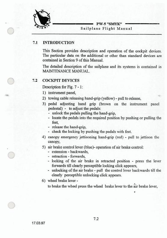
7.1 INTRODUCTION
This Section pmvides description and operation of the cockpit devices. The particular data on the additional or other than standard devices are contained in Section 9 of this Manual.
The detailed description of the sailplane and its systems is contained in MAINTENANCE MANUAL.
0 7.2 COCKPIT DEVICES
Description for Fig. 7 - 1: 1) instrument panel
@& - 2) towing cable releasing hand-grip (yellow) - pull to release, 3) pedal adjusting hand grip (brown on the instrument panel
pedestal) - to adjust the pedals: - d o c k the pedals pulling the hand-grip, - looate the pedals into the required position by pushing or pulling the
feef - release the hand-grip, - check the locking by pushing the pedals with feet.
4) canopy emergency jettisoning hand-grip (red) - pull to jettison the canopy,
5) air hrake control lever (bluek operation ofair brake control: - extension -backwards,
('3 - retraction - forwards, - locking of the air brake in retracted position - press the lever
fonvards till clearly perceptible locking click appears, - unlocking of the air brake - pull the control 1-1 backwards till the
clearly perceptible nnlocLing click appears. 6) wheel brake lever -
to hrake the wheel press the wheel brake lever to the & brake le~er,
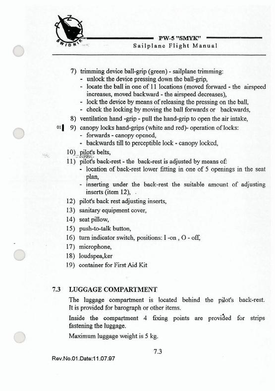
k ' * ID* ' . Sa i lp l ane PW-5 Fl ight "GMYIC' Manual
7) trimming device ball-grip (green) - sailplane trimming: - unlock the device pressing down the ball-grip, - locate the ball in one of 11 locations (moved forward - the airspeed
increase5 moved backward - the airspeed decreases), - lock the device by means of releasing the pressing on the ball, - check the locking by moving the ball forwards or backwards,
8) ventilation hand -grip - pull the hand-grip to open the air intake,
-) 011 9) canopy locks hand-grips (white and red)- operation of locks: - fxwards - canopy opened, - backwards till to perceptible lock - canopy locked,
.< lo)..*s belts, 11)' back-rest - the back-rest is adjusted by means of:
- location of back-rest lower fitting in one of 5 openings in the seat plan,
- inserting under the back-rest the suitable amount of adjusting inserts (item 12), .
12) pilot's back rest adjusting inserts, 13) sanitary equipment cover, 14) seat pillow, 15) push-to-talk button, 16) turn indicator switch, positions: I -on, 0 - off, 17) microphone, 18) loudspa,ker 19) container for First Aid Kit
7.3 LUGGAGE COMPARTMENT
The laggage compartment is located behind the p.2ot's back-rest. Jt is provided for barograph or other items.
Inside the compaFtment 4 fixing points are proviaed for strips fastening the luggage.
Maximum luggage weight is 5 kg.

m - 5 "BMYK" Sailpfdn~'F1ikht Manual
cockpitdeYices Fig. 7 - 1

Fw-5 " S m ' -- ' .. Sailplane Flight Manual - - - , s
-- n
7.4 INFORMATION PLACARDS IN COCKPIT The operation limitations placards are described in Section 2. Rigging and de-rigging placards and location of the placards are described in MAINTENANCE MANUAL.
13
I I I
back-rest adjustment trimming device
cable releasing I
pedal adjustment
1 1 - 9 . 7 - 5 - 3 . - 1 locatim of trimming device
canopy locks cookpit ventilation canopy jettison
Information placards in cockpit Fig.7-2
- PW-5 "SMYIC'
7 S a i l p l a n e F l i g h t Manual
SECTION 8
S A I L P L A N E H A N D L I N G , C A R E A N D M A I N T E N A N C E
0 8.1 INTRODUCTION
w 8.2 SAILPLANE INSPECTION PERIODS
8.3 SAILPLANE ALTERATIONS OR REPAIRS
8.4 GROUND HANDLJNG, ROAD TRANSPORTATION
8.5 CLEANING AND STORING
PW-5 "GMYIC' Sa i lp l ane Fl ight Manual
This Section contains manufacturer's recommended procedures for proper ground handling of the sailplane. It also identifies the inspection and ground handling requirements, which must be followed to retain the performance and condition of new sailplane.
8.2 SAILPLANE INSPECTION PERIODS
The sailplane inspection periods and range are contained in MAINTENANCE MANUAL.
8.3 Sc;TLPLANE ALTERATIONS OR REPAIRS
It is'essential that the responsible airworthiness Authority be contacted &OJ to any alternation on the sailplane to ensure that the a~rworthiness of the sailplane is not compromised.
For repairs rder to MAINTENANCE MANUAL.
The sailplane external surfaces should have the write, not getting yellow, Lacquer covering.
On the upper surfaces of wings, tnilplane and fuselage no colour markings are allowed (it does not consider the colour markings of the wing tips).
On the control surfaces no markings are allowed to be painted, except producer mark on the rudder which are considered in the mass bdance of the rudder.
8.4 GROUND HANDLING, ROAD TR4NSPORTATlON TAXIING
The sailplane may be taxied by means of motored vehicle or other device using the h n t hook. The maximum allowed taxiing speed is 3 kts. The general transportation rules should be observed. During the taxiing the canopy should be locked, and the control stick fastened with the pilot's belts.
NOTE:
Pushing the sailplane on the wing tips or tailplane tips as well as the control surfaces is prohibited.

- *J?W7-5-"61\IYIC'
' 7 ~ a W p l W e FlTght Manual
PARKING ON AIRmELD When parlcing on the airfield the canopy should be locked and protected wirh a cover.
NOTE:
The non-anehored sailplane cannot be left without the supervision A
0 ANCHORING - put the sailplane in such a position that the wind blows h m back-side
dimtion, '4 - * I ?.-*
- put the wing against the wind, - anchor the sailplane on wing tip, h n t hook and end of fuselage, - immobilise the stick by means of pilots belts.
ROAD TRANSPORTATION To prepare the sailplane for a transportation: - check the sailplane to be complete, - emptify the cockpif - immobilise the control stick by means of pilots helts, - lock the canopy and close the window, - put the cover on the canopy,
0 - secure the control systems ends protruding out of the wings to avoid the damages,
- imnobiise the ailerons and rudder by means of fixators, - fix the sailplane components on the trailer on the way that the
possibility of damage is excluded (see - storing, the tailplane may be located horizontally).
NOTE: 3
When the opened trniler is used secure the sailplane with covers.
PW-5 "SMYJC' - Snilplane Flight Manua-I -
8.5 CLEANING AND STORING
CLEANING The sailplane should be washed with water mixed with the normal detergents using the sponge or soft rag. After washing the pe~ousness of drainage holes should be checked and, if necessary, the structure inside dried (this concerns especially the air brake boxes). For wnshing the textile elements the special cleaning agents should be used acc. to the recommendation of their producers. The cockpit should be regularly cleaned with the vacuum cleaner.
NOTE:
Do not use the organic solvents (gasoline, nih-o etc.) for canopy perapex cleaning.
STORING The sailplane should be stored in dry and ventilated room. In case of prolonged storage it is necessary to protect the fittings against a corrosion (e.g. with a grease).
When stored in de-rigged condition its components should be positioned in the way that excludes thc possibility of pennanent deformations to be got: - wings - leading edge downwards, supported on the spar roots (near
the root rib) and leading edge near the trapeze part end using the soft, fitted stillage,
- fuselage - on wheels, the support under the tail skid. It is also possible to support the fuselage near the cockpit with a so4 fitted stillage.
- tailplane- loading edge downwards; both tips supported on the soft, fitted stillages. .4
NOTE:
After parking the sailplane on the open air it is necessary to check for the water inside the structure, then dry, dean and ventilate the whole sailplane.

.* PW-5 "SMYIC'
c \ S a i l p l a n e F l i g h t Manual
SECTION 9
S U P P L E M E N T S
0 9.1 INTRODUCTION
9.2 LIST OF INSERTED SUPPLEMENTS

L *,on\.-=. PW-5 "SMYK"
,+\ Sailplane Flight Manual
This Section contains the appropriate supplements necessary for the safe and efficient operation of the sailplane when equipped with various optional systems and equipment not provided with the standard sailplane.
LIST OF INSERTED SUPPLEMENTS