Embed Size (px)
Citation preview
Vehicle Control
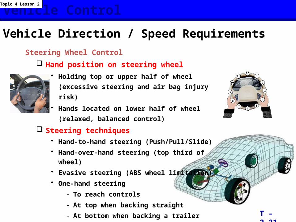
Vehicle Direction / Speed RequirementsSteering Wheel Control
Hand position on steering wheel• Holding top or upper half of wheel (excessive steering and
air bag injury risk)
• Hands located on lower half of wheel (relaxed, balanced
control)
Steering techniques• Hand-to-hand steering (Push/Pull/Slide)• Hand-over-hand steering (top third of wheel)• Evasive steering (ABS wheel limitation)• One-hand steering
- To reach controls
- At top when backing straight
- At bottom when backing a trailer
T – 2.31
Topic 4 Lesson 2
Targeting and Visual Requirements
T – 2.32
Topic 5 Lesson 1
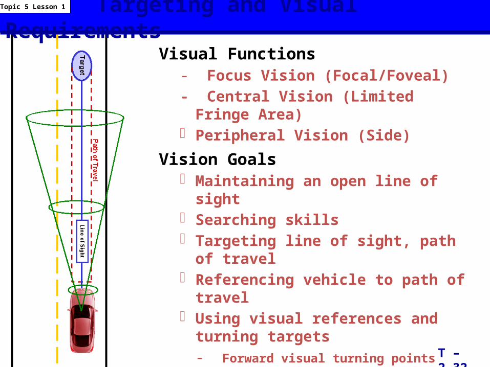
Visual Functions- Focus Vision (Focal/Foveal)- Central Vision (Limited Fringe Area)- Peripheral Vision (Side)
Vision Goals- Maintaining an open line of sight- Searching skills- Targeting line of sight, path of travel- Referencing vehicle to path of travel- Using visual references and turning targets
- Forward visual turning points- Rear visual turning points
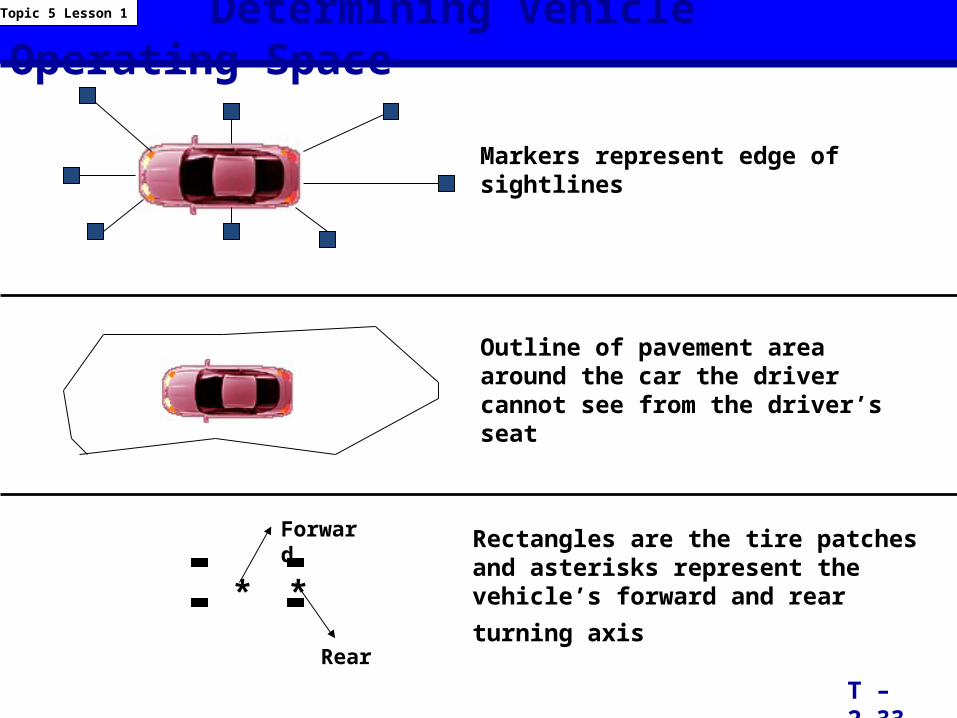
Determining Vehicle Operating Space
Markers represent edge of sightlines
Outline of pavement area around the car the driver cannot see from the driver’s seat
Rectangles are the tire patches and asterisks represent the vehicle’s forward and rear
turning axis
T – 2.33
Topic 5 Lesson 1
* *
Forward
Rear
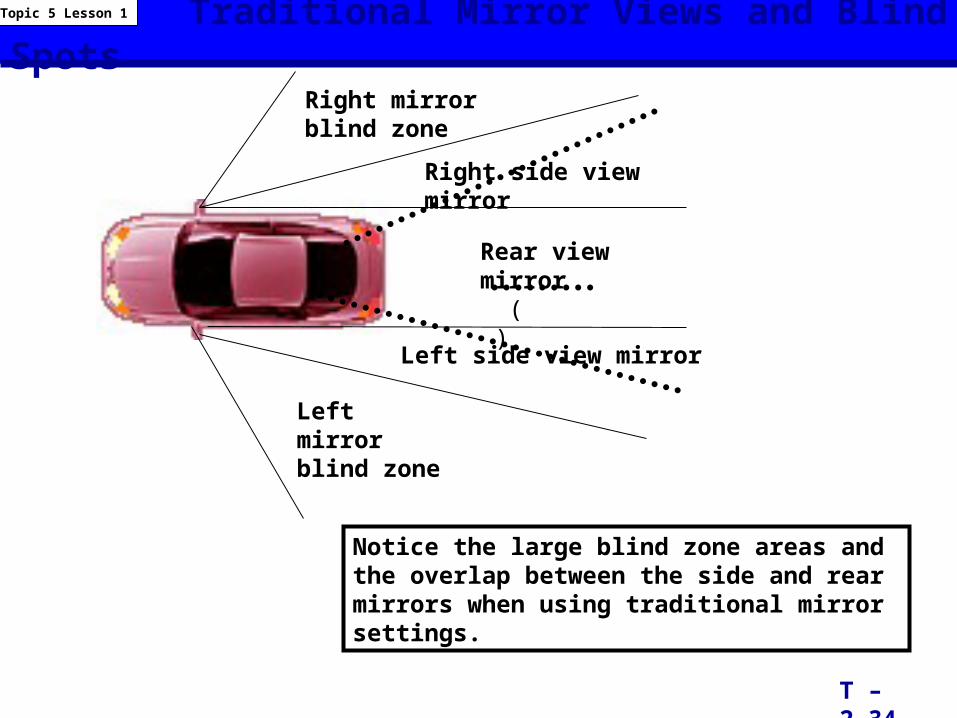
Traditional Mirror Views and Blind Spots
Notice the large blind zone areas and the overlap between the side and rear mirrors when using traditional mirror settings.
T – 2.34
Topic 5 Lesson 1
Rear view mirror ( )
Left side view mirror
Right side view mirror
Left mirror blind zone
Right mirror blind zone
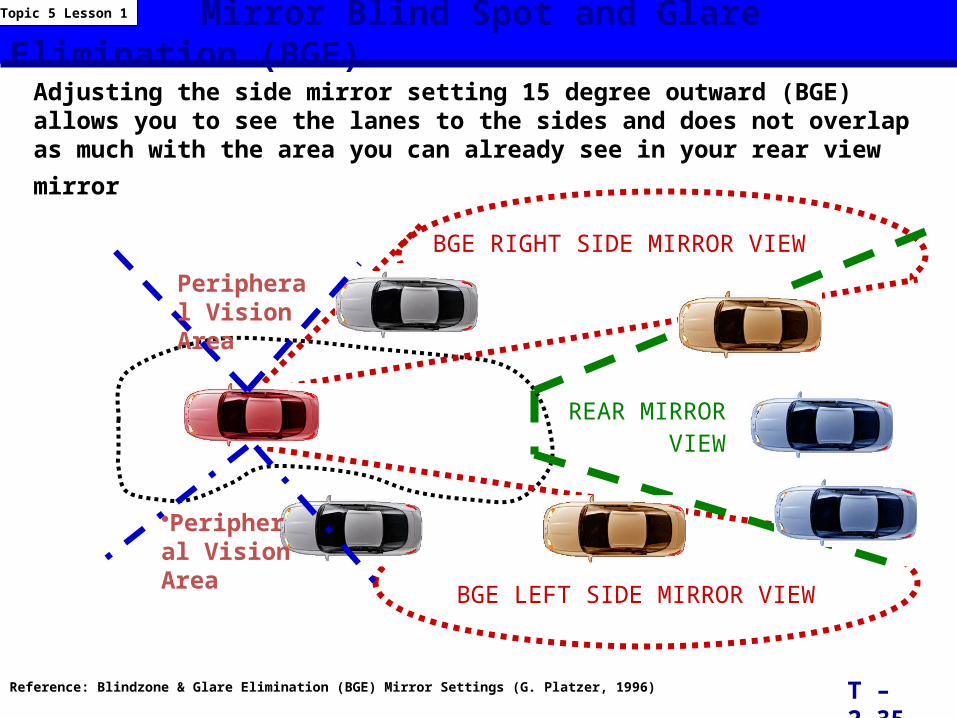
Mirror Blind Spot and Glare Elimination (BGE)
BGE LEFT SIDE MIRROR VIEW
BGE RIGHT SIDE MIRROR VIEW
REAR MIRROR VIEW
Reference: Blindzone & Glare Elimination (BGE) Mirror Settings (G. Platzer, 1996)
Adjusting the side mirror setting 15 degree outward (BGE) allows you to see the lanes to the sides and does not overlap as much with the area you can already see in your rear
view mirror
T – 2.35
Topic 5 Lesson 1
•Peripheral Vision Area
Peripheral Vision Area
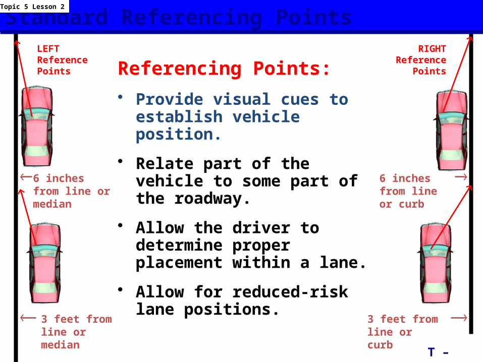
Standard Referencing Points
Referencing Points:
• Provide visual cues to establish vehicle position.
• Relate part of the vehicle to some part of the roadway.
• Allow the driver to determine proper placement within a lane.
• Allow for reduced-risk lane positions.
T – 2.36
Topic 5 Lesson 2
RIGHT Reference
Points
LEFT Reference Points
6 inches from line or median
3 feet from line or median
6 inches from line or curb
3 feet from line or curb
Front LimitationFr
ont
Lim
itatio
n
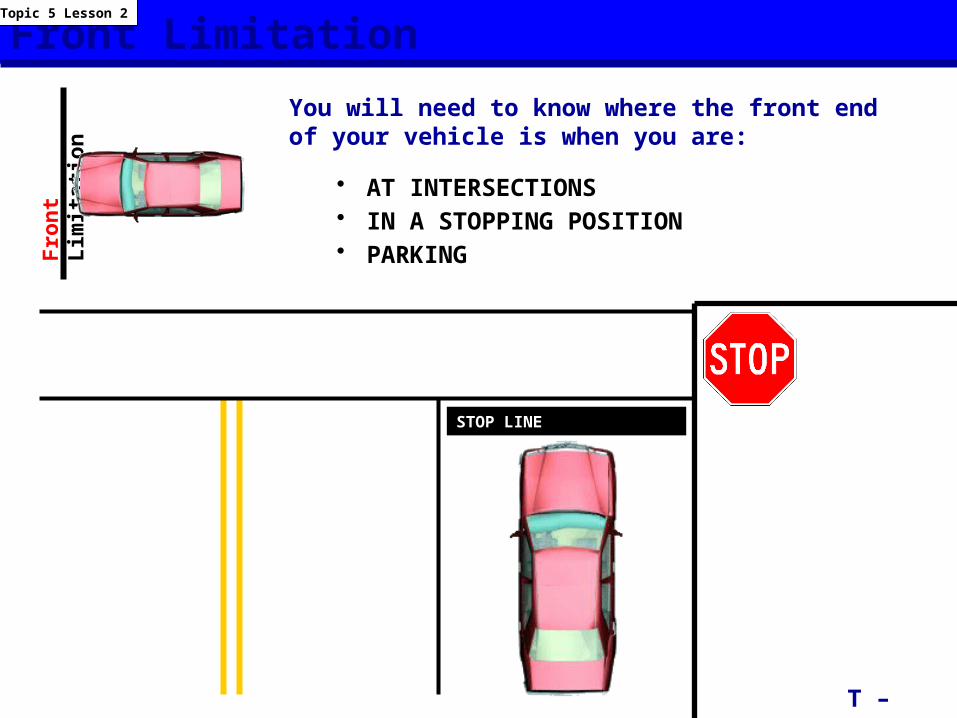
• AT INTERSECTIONS• IN A STOPPING POSITION• PARKING
You will need to know where the front end of your vehicle is when you are:
T – 2.37
Topic 5 Lesson 2
STOP LINE
Front Limitation
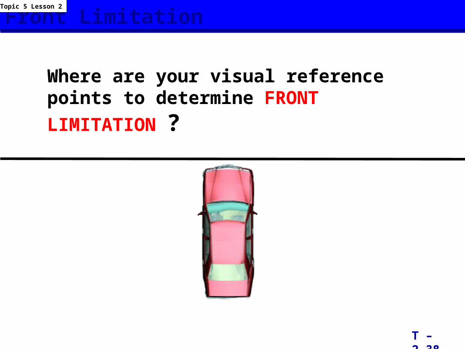
Where are your visual reference points to determine FRONT LIMITATION ?
T – 2.38
Topic 5 Lesson 2
Front Limitation Reference Points
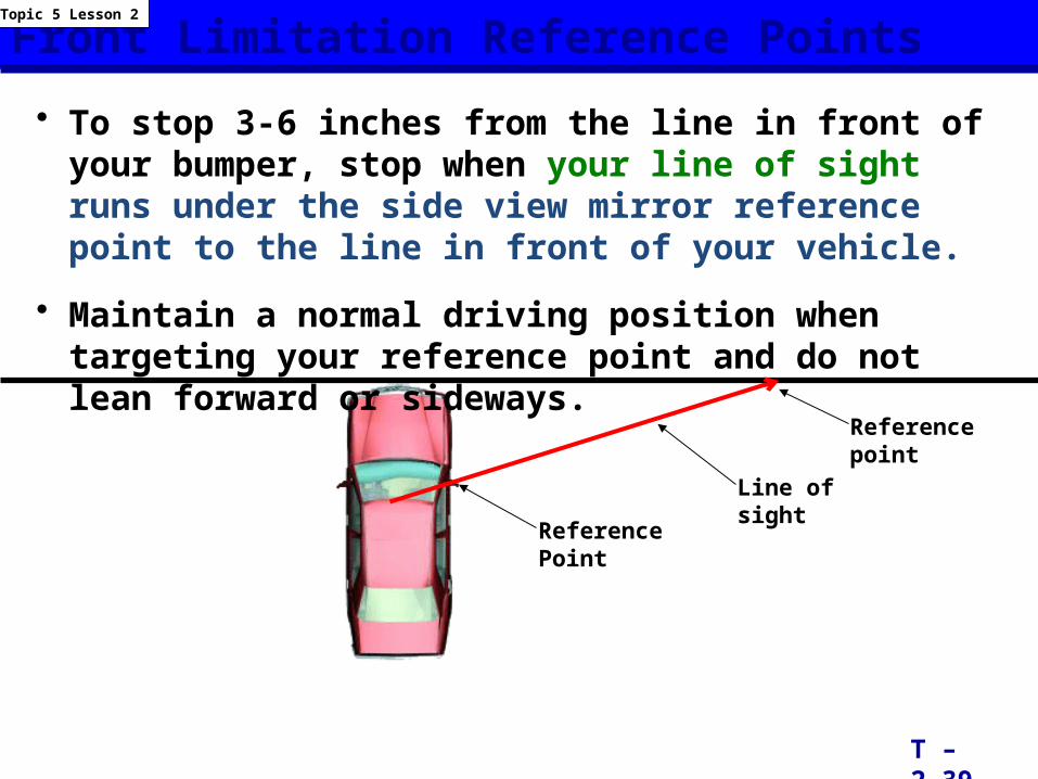
• To stop 3-6 inches from the line in front of your bumper, stop when your line of sight runs under the side view mirror reference point to the line in front of your vehicle.
• Maintain a normal driving position when targeting your reference point and do not lean forward or sideways.
T – 2.39
Topic 5 Lesson 2
Reference Point
Line of sight
Reference point
Rear Limitation
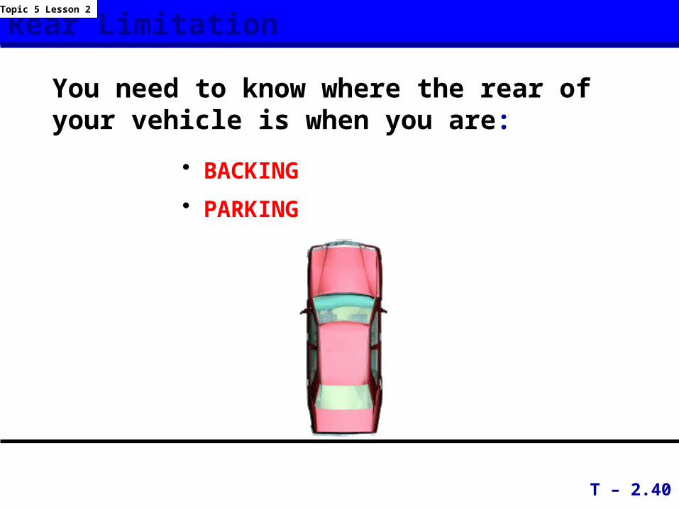
• BACKING
• PARKING
You need to know where the rear of your vehicle is when you are:
T – 2.40
Topic 5 Lesson 2
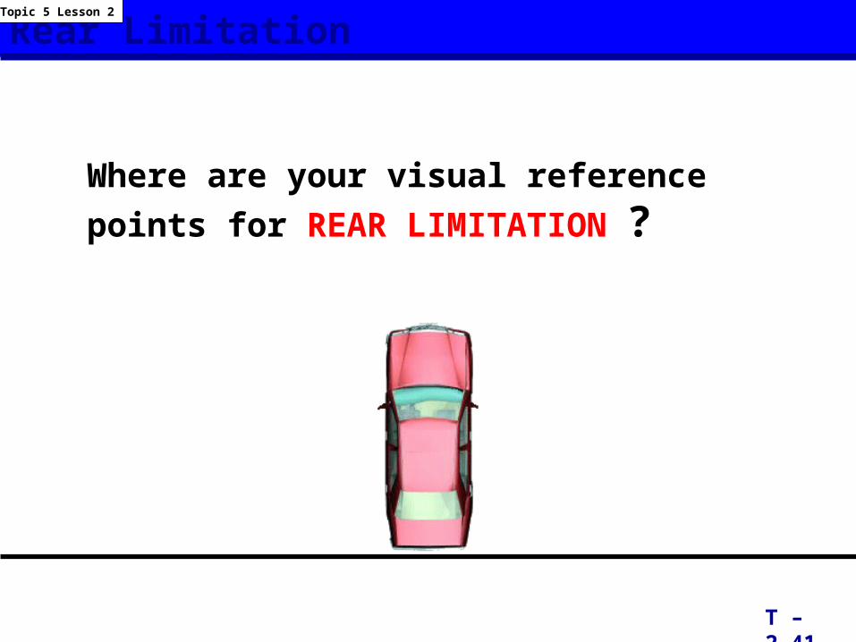
Rear Limitation
T – 2.41
Topic 5 Lesson 2
Where are your visual reference points for REAR LIMITATION ?
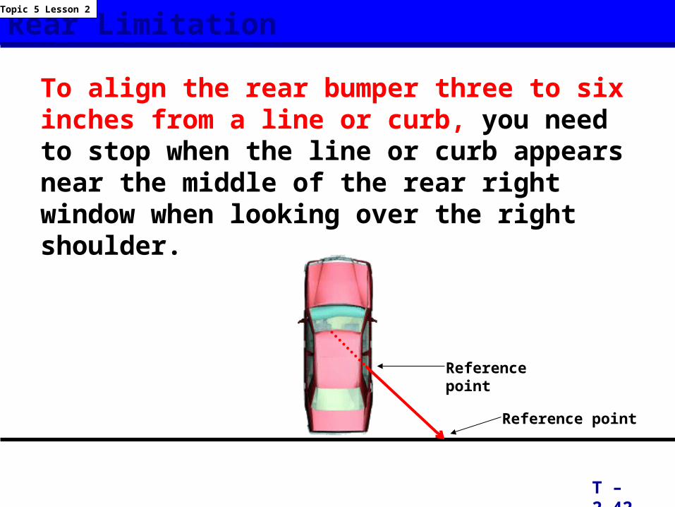
Rear Limitation
To align the rear bumper three to six inches from a line or curb, you need to stop when the line or curb appears near the middle of the rear right window when looking over the right shoulder.
T – 2.42
Topic 5 Lesson 2
Reference point
Reference point
Right Side Limitation
T – 2.43
Topic 5 Lesson 2
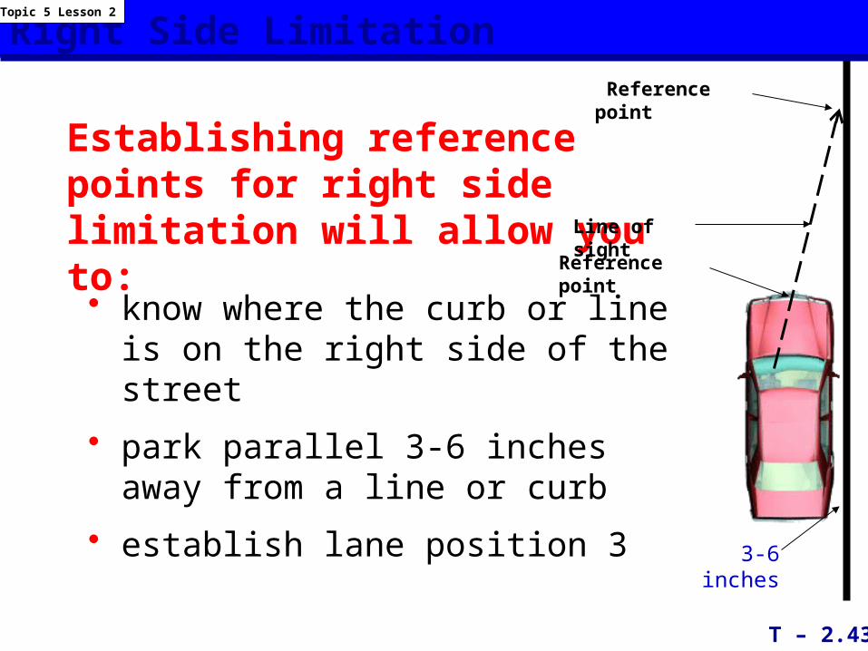
Establishing reference points for right side limitation will allow you to:
• know where the curb or line is on the right side of the street
• park parallel 3-6 inches away from a line or curb
• establish lane position 33-6 inches
Line of sight
Reference point
Reference point

Right Side Limitation
T – 2.44
Topic 5 Lesson 2
The right side limitation reference point to position your vehicle 3-6 inches from the curb or line is the middle of your vehicle’s hood.
3-6 inches
Line of Sight Reference point
The reference point for 3 feet from the curb or line is the right 1/4 section of the hood.
3 feet
Reference point
Line of Sight
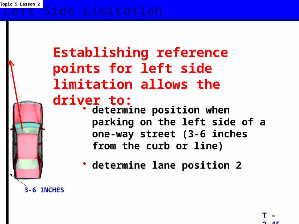
Left Side Limitation
• determine position when parking on the left side of a one-way street (3-6 inches from the curb or line)
• determine lane position 2
T – 2.45
Topic 5 Lesson 2
3-6 INCHES
Establishing reference points for left side limitation allows the driver to:
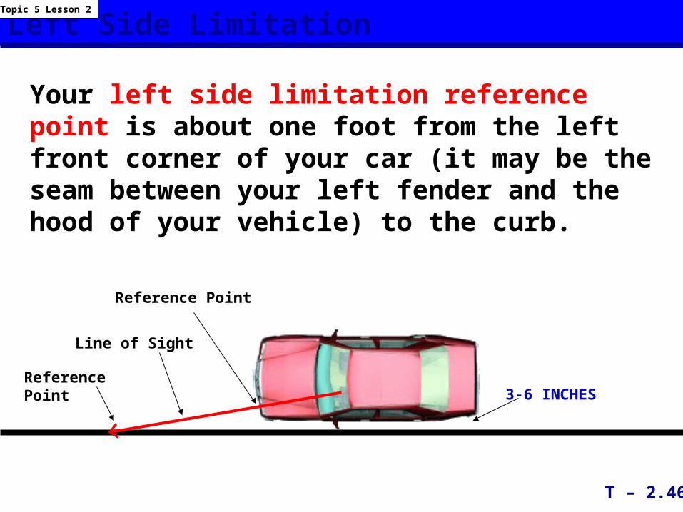
Left Side Limitation
Your left side limitation reference point is about one foot from the left front corner of your car (it may be the seam between your left fender and the hood of your vehicle) to the curb.
T – 2.46
Topic 5 Lesson 2
3-6 INCHES
Reference Point
Line of Sight
Reference Point
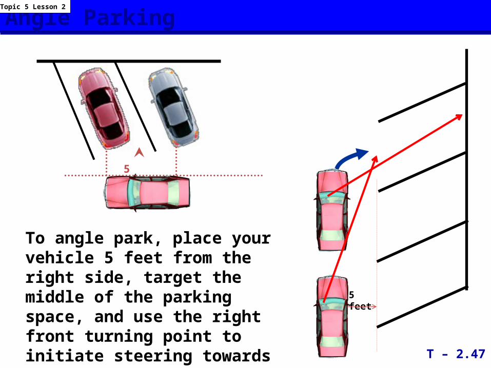
Angle Parking
5 Feet
To angle park, place your vehicle 5 feet from the right side, target the middle of the parking space, and use the right front turning point to initiate steering towards the middle of space.
5 feet
T – 2.47
Topic 5 Lesson 2
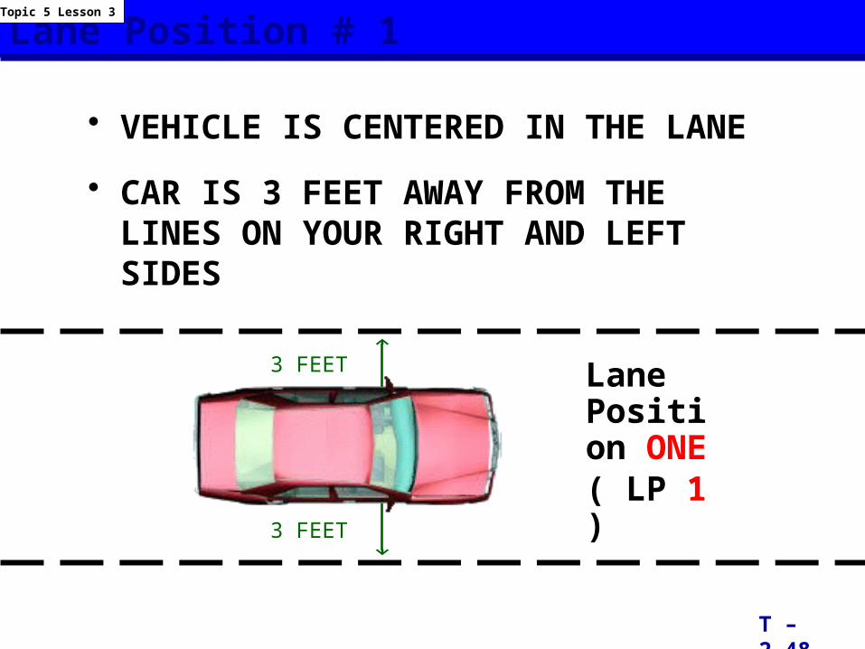
Lane Position # 1
• VEHICLE IS CENTERED IN THE LANE
• CAR IS 3 FEET AWAY FROM THE LINES ON YOUR RIGHT AND LEFT SIDES
T – 2.48
Topic 5 Lesson 3
3 FEET
3 FEET
Lane Position ONE( LP 1 )
Lane Position # 1
Lane Position ONE
(LP 1)
T – 2.49
Topic 5 Lesson 3
3 FEET
3 FEET
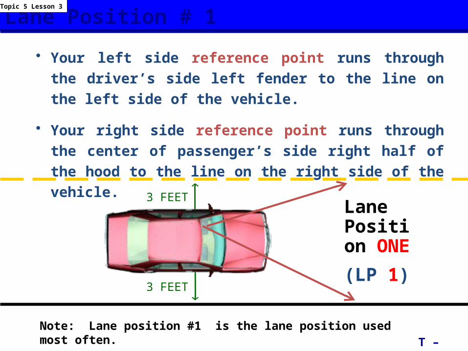
• Your left side reference point runs through the driver’s side left fender to the line on the left side of the vehicle.
• Your right side reference point runs through the center of passenger’s side right half of the hood to the line on the right side of the vehicle.
Note: Lane position #1 is the lane position used most often.
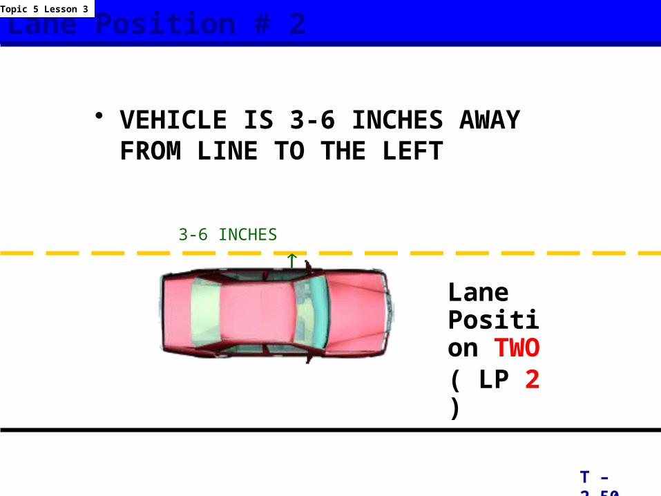
Lane Position # 2
• VEHICLE IS 3-6 INCHES AWAY FROM LINE TO THE LEFT
T – 2.50
Topic 5 Lesson 3
3-6 INCHES
Lane Position TWO( LP 2 )
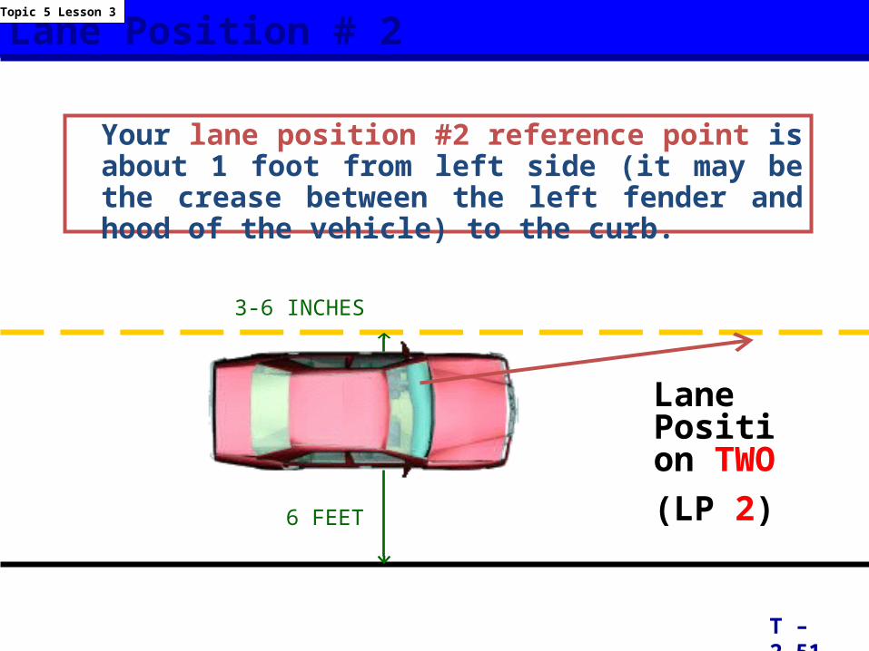
Lane Position # 2
Your lane position #2 reference point is about 1 foot from left side (it may be the crease between the left fender and hood of the vehicle) to the curb.
T – 2.51
Topic 5 Lesson 3
Lane Position TWO(LP 2)
3-6 INCHES
6 FEET
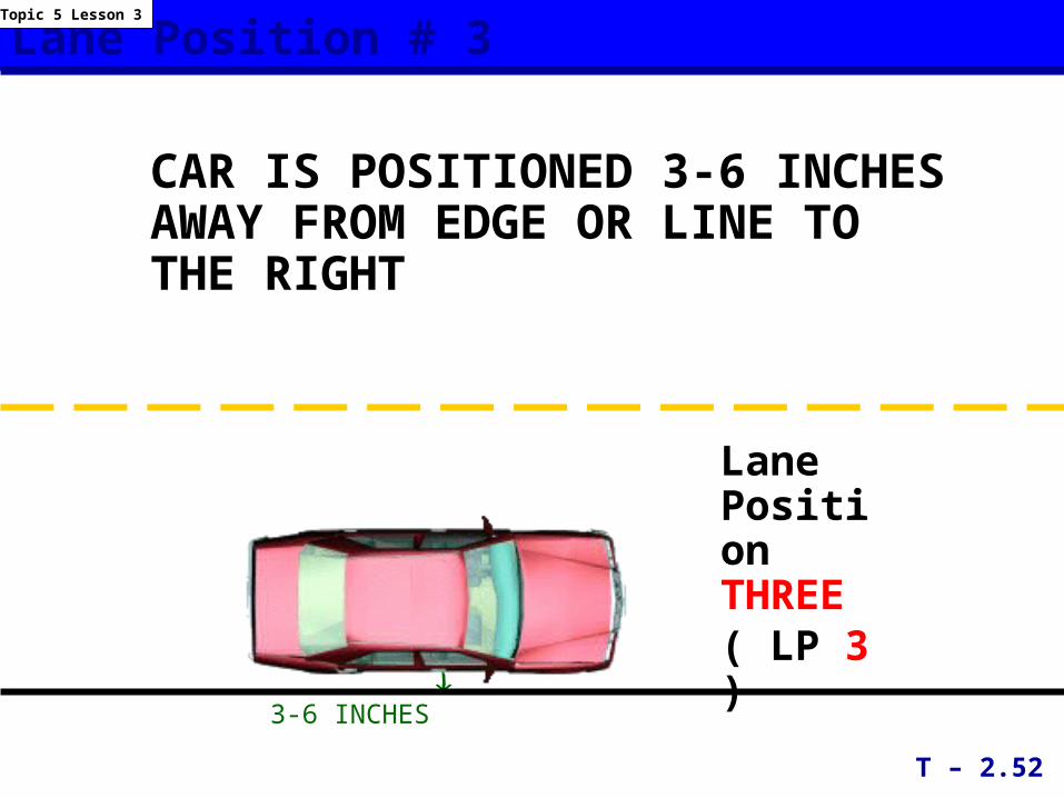
Lane Position # 3
CAR IS POSITIONED 3-6 INCHES AWAY FROM EDGE OR LINE TO THE RIGHT
T – 2.52
Topic 5 Lesson 3
3-6 INCHES
Lane Position THREE( LP 3 )
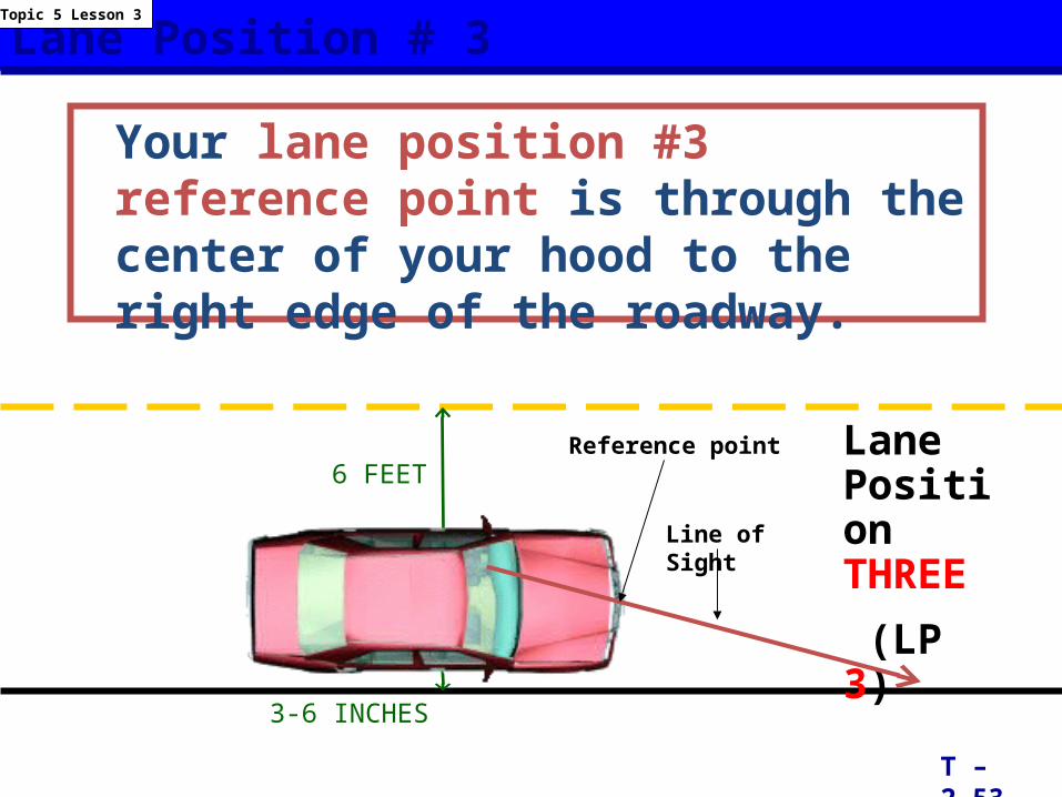
Lane Position # 3
Your lane position #3 reference point is through the center of your hood to the right edge of the roadway.
T – 2.53
Topic 5 Lesson 3
Lane Position THREE
(LP 3)
3-6 INCHES
6 FEETReference point
Line of Sight
Lane Positions
LP 1
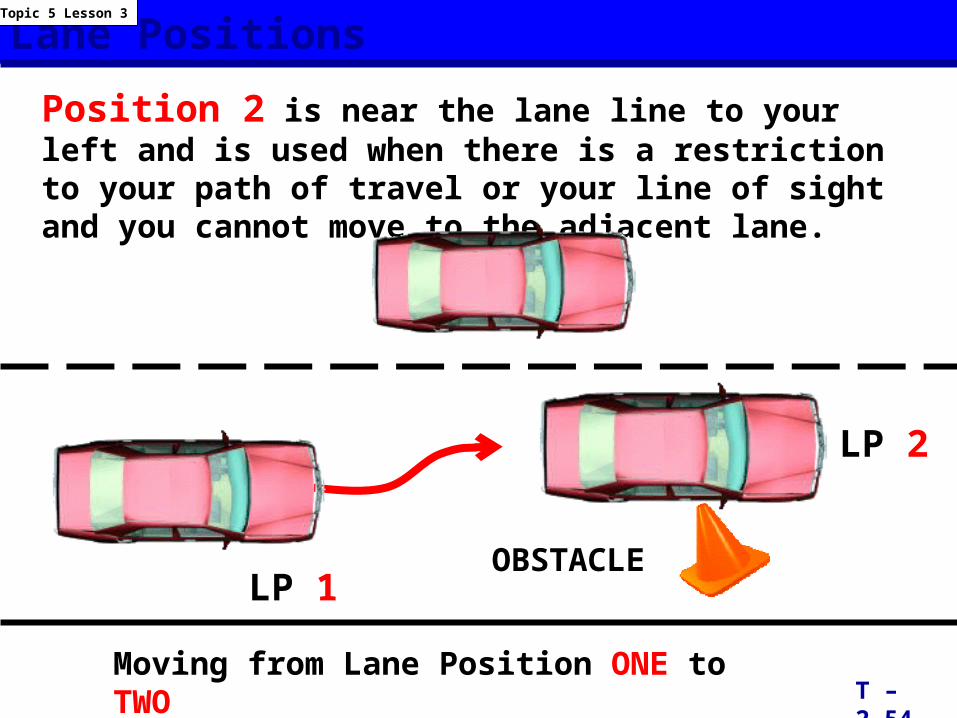
Position 2 is near the lane line to your left and is used when there is a restriction to your path of travel or your line of sight and you cannot move to the adjacent lane.
T – 2.54
Topic 5 Lesson 3
Moving from Lane Position ONE to TWO
LP 2
OBSTACLE
Lane Positions
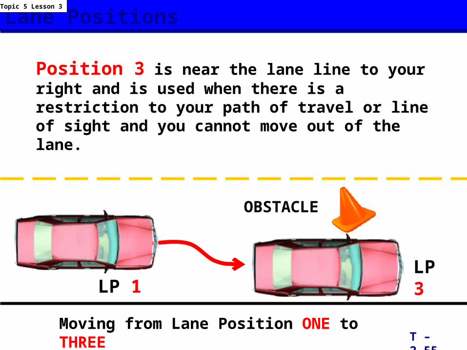
Position 3 is near the lane line to your right and is used when there is a restriction to your path of travel or line of sight and you cannot move out of the lane.
T – 2.55
Topic 5 Lesson 3
Moving from Lane Position ONE to THREE
LP 1LP 3
OBSTACLE
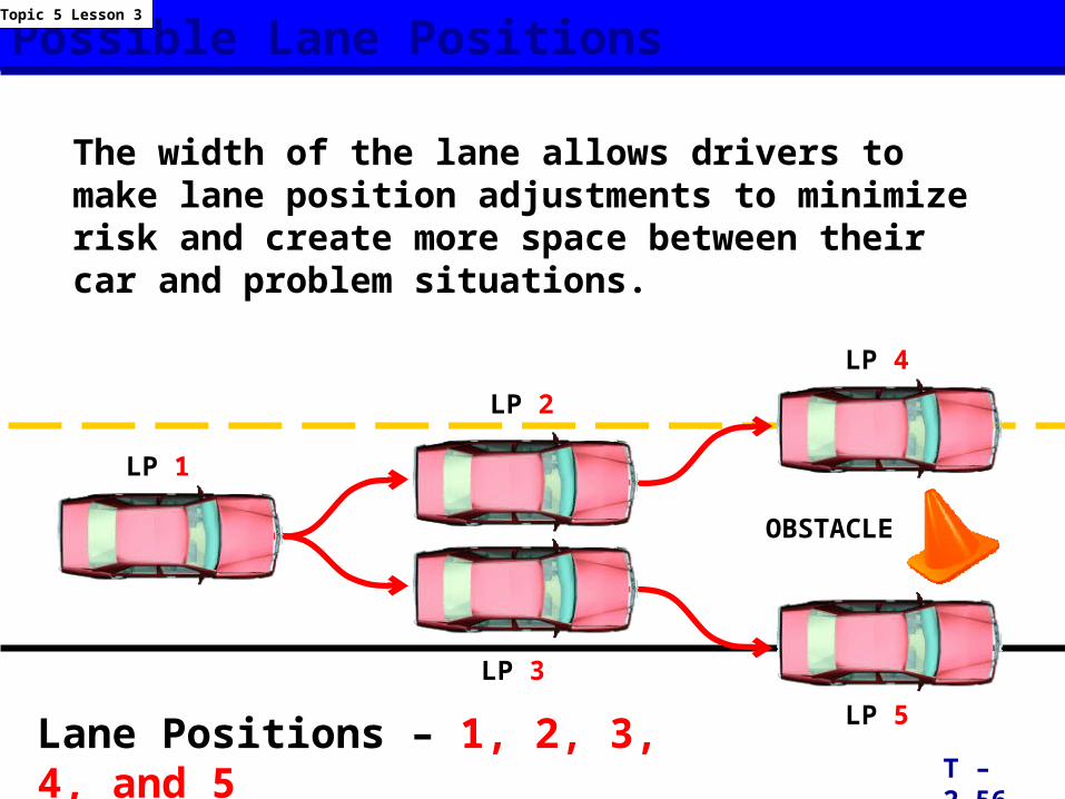
Possible Lane Positions
The width of the lane allows drivers to make lane position adjustments to minimize risk and create more space between their car and problem situations.
T – 2.56
Topic 5 Lesson 3
Lane Positions – 1, 2, 3, 4, and 5
LP 3
LP 2
LP 4
LP 5
LP 1
OBSTACLE
Basic Maneuvering Tasks:
Low Risk Environment
Topic 1 -- Basic Maneuvers
Topic 2 -- Vision and Perception
Topic 3 -- Controlling Risk Using a Space Management System
Topic 4 -- Developing Good Driving Habits
Module Three Transparencies
Virginia Department of Education
Provided in cooperation with the Virginia Department of Motor Vehicles
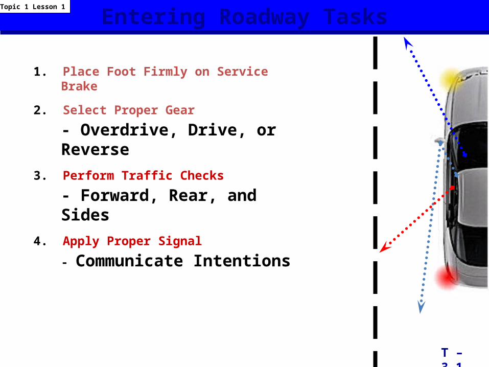
1. Place Foot Firmly on Service Brake
2. Select Proper Gear
- Overdrive, Drive, or Reverse3. Perform Traffic Checks
- Forward, Rear, and Sides4. Apply Proper Signal
- Communicate Intentions
T – 3.1
Entering Roadway TasksTopic 1 Lesson 1
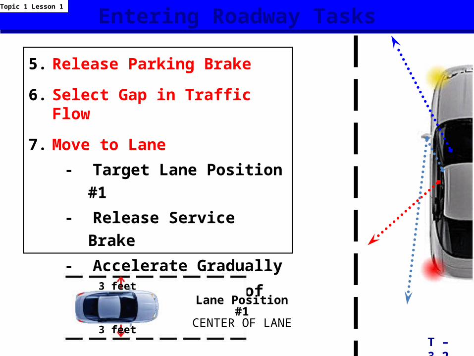
5. Release Parking Brake
6. Select Gap in Traffic Flow
7. Move to Lane
- Target Lane Position #1
- Release Service Brake
- Accelerate Gradually
- Steer to Center of Lane
Entering Roadway Tasks
T – 3.2
Topic 1 Lesson 1
3 feetLane Position #1CENTER OF LANE
3 feet
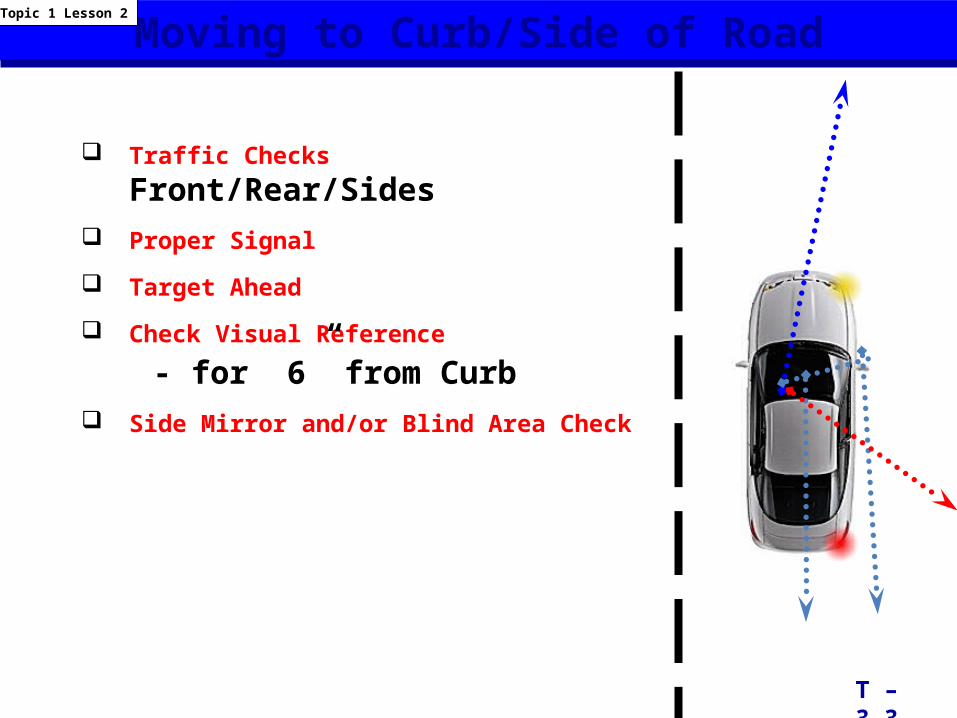
Traffic Checks Front/Rear/Sides Proper Signal
Target Ahead
Check Visual Reference
- for 6” from Curb Side Mirror and/or Blind Area Check
T – 3.3
Moving to Curb/Side of RoadTopic 1 Lesson 2
Moving to Curb/Side of Road
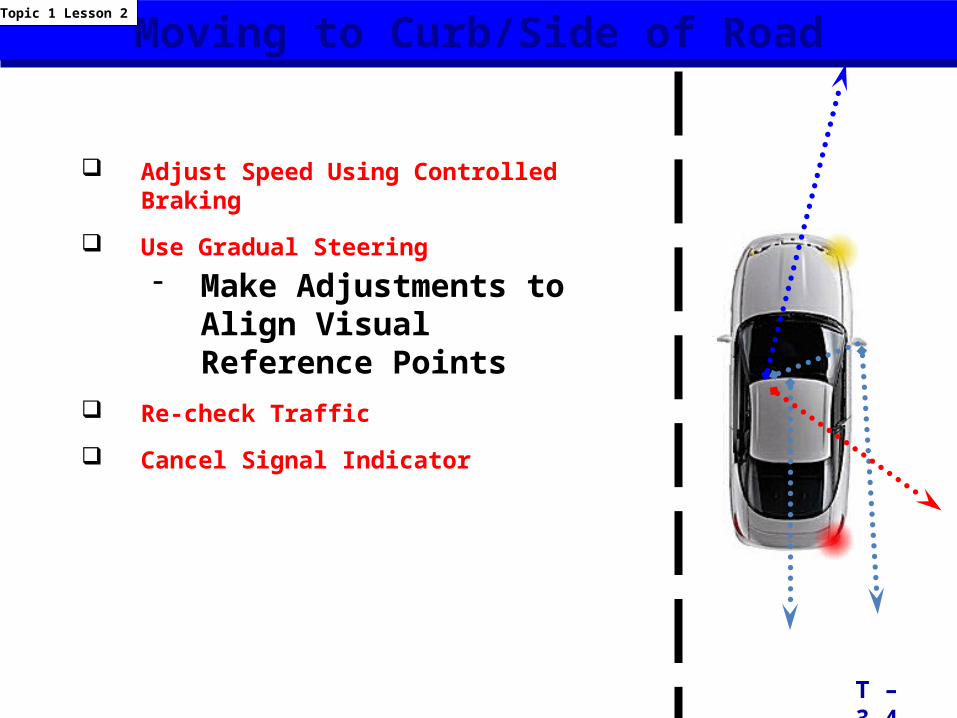
Adjust Speed Using Controlled Braking
Use Gradual Steering - Make Adjustments to Align
Visual Reference Points Re-check Traffic
Cancel Signal Indicator
T – 3.4
Topic 1 Lesson 2
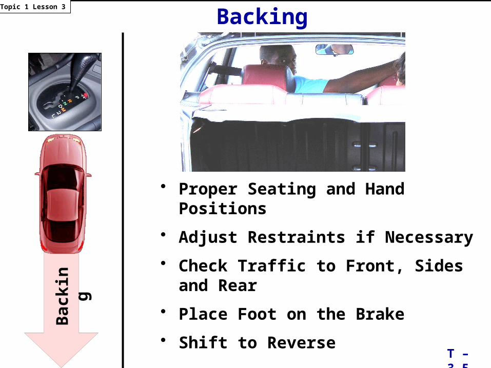
• Proper Seating and Hand Positions
• Adjust Restraints if Necessary
• Check Traffic to Front, Sides and Rear
• Place Foot on the Brake
• Shift to Reverse
T – 3.5
Topic 1 Lesson 3
Back
ing
Backing
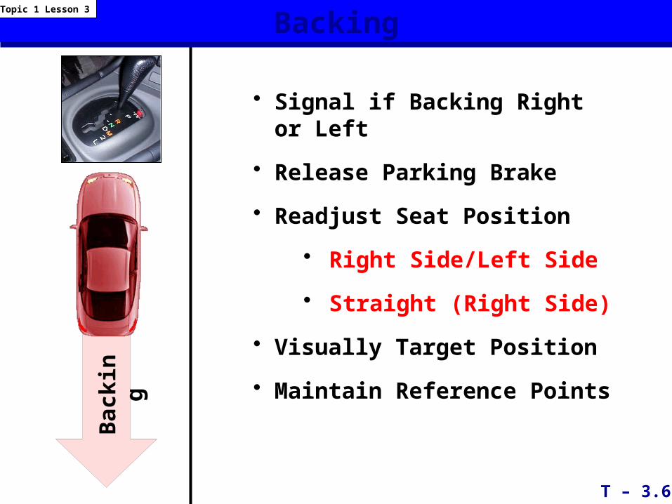
• Signal if Backing Right or Left
• Release Parking Brake
• Readjust Seat Position
• Right Side/Left Side
• Straight (Right Side)
• Visually Target Position
• Maintain Reference Points
T – 3.6
BackingTopic 1 Lesson 3
Back
ing
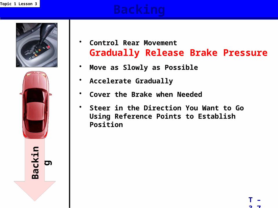
• Control Rear Movement Gradually Release Brake Pressure
• Move as Slowly as Possible
• Accelerate Gradually
• Cover the Brake when Needed
• Steer in the Direction You Want to Go Using Reference Points to Establish Position
Backing
T – 3.7
Topic 1 Lesson 3
Back
ing
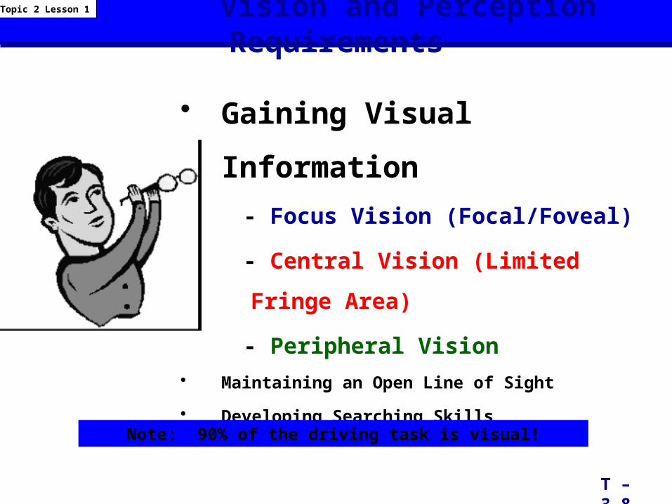
• Gaining Visual Information
- Focus Vision (Focal/Foveal)
- Central Vision (Limited Fringe Area)
- Peripheral Vision• Maintaining an Open Line of Sight
• Developing Searching Skills
Vision and Perception Requirements
T – 3.8
Topic 2 Lesson 1
Note: 90% of the driving task is visual!
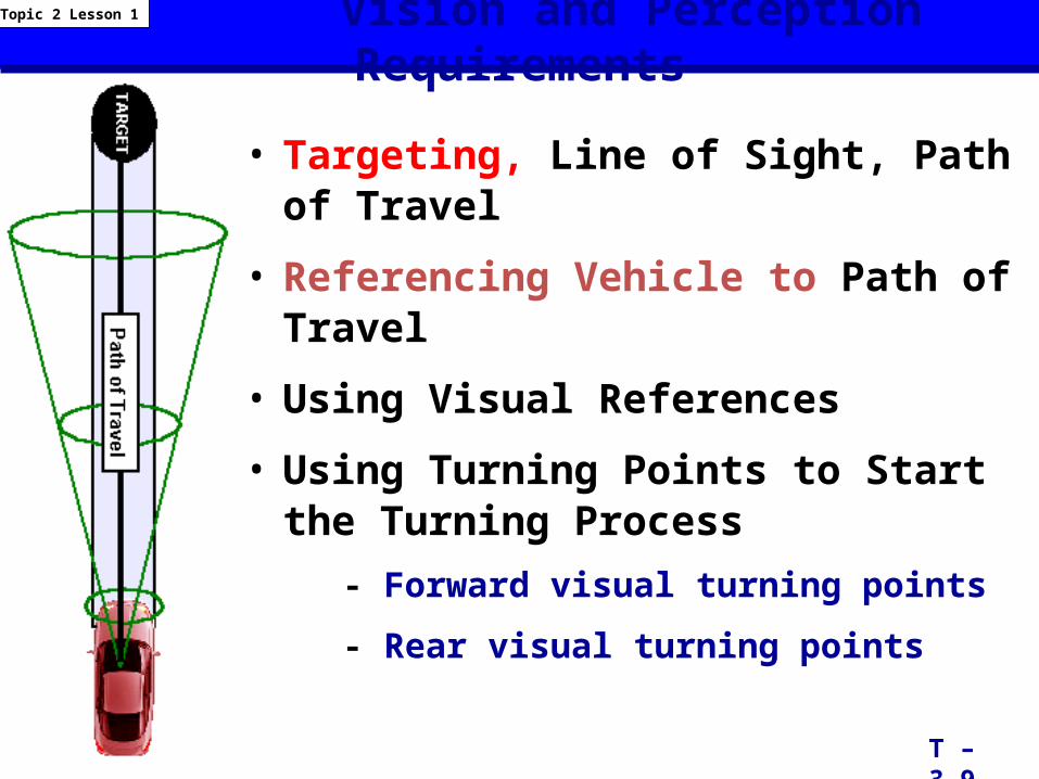
Vision and Perception Requirements
• Targeting, Line of Sight, Path of Travel
• Referencing Vehicle to Path of Travel
• Using Visual References
• Using Turning Points to Start the Turning Process
- Forward visual turning points
- Rear visual turning points
T – 3.9
Topic 2 Lesson 1
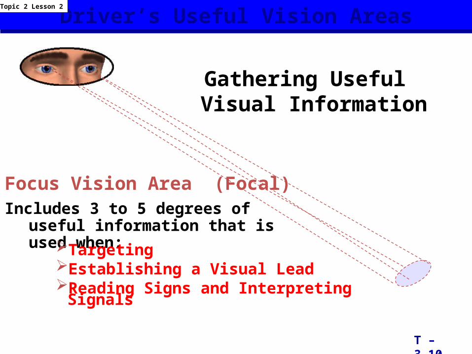
Driver’s Useful Vision Areas
Gathering Useful Visual Information
Focus Vision Area (Focal) Includes 3 to 5 degrees of useful
information that is used when:TargetingEstablishing a Visual LeadReading Signs and Interpreting Signals
T – 3.10
Topic 2 Lesson 2
Driver’s Useful Vision Areas
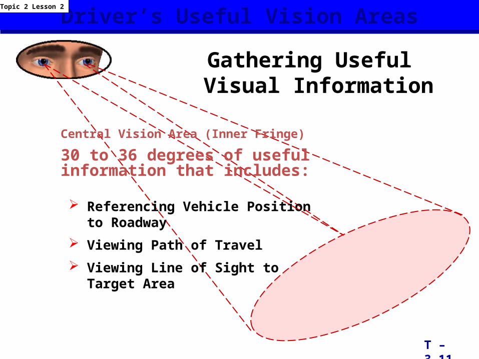
Referencing Vehicle Position to Roadway
Viewing Path of Travel
Viewing Line of Sight to Target Area
T – 3.11
Topic 2 Lesson 2
Gathering Useful Visual Information
Central Vision Area (Inner Fringe)
30 to 36 degrees of useful information that includes:
Driver’s Useful Vision Areas
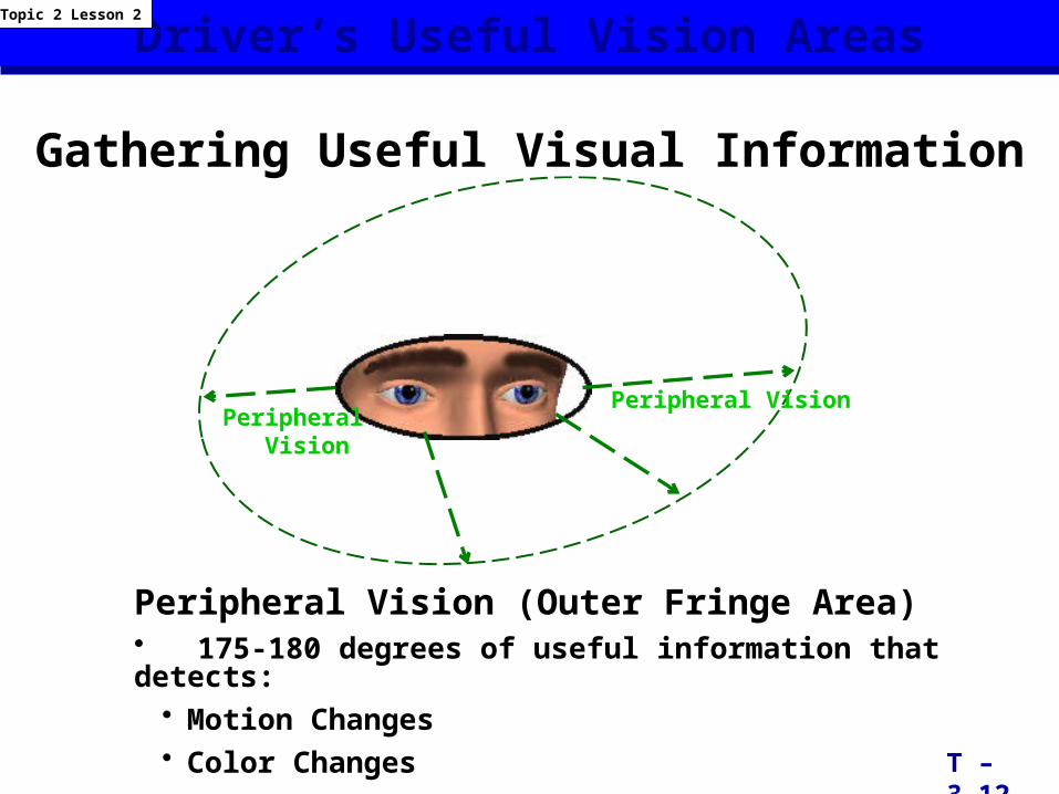
Gathering Useful Visual Information
T – 3.12
Topic 2 Lesson 2
Peripheral Vision
Peripheral Vision
Peripheral Vision (Outer Fringe Area)• 175-180 degrees of useful information that detects:
• Motion Changes• Color Changes
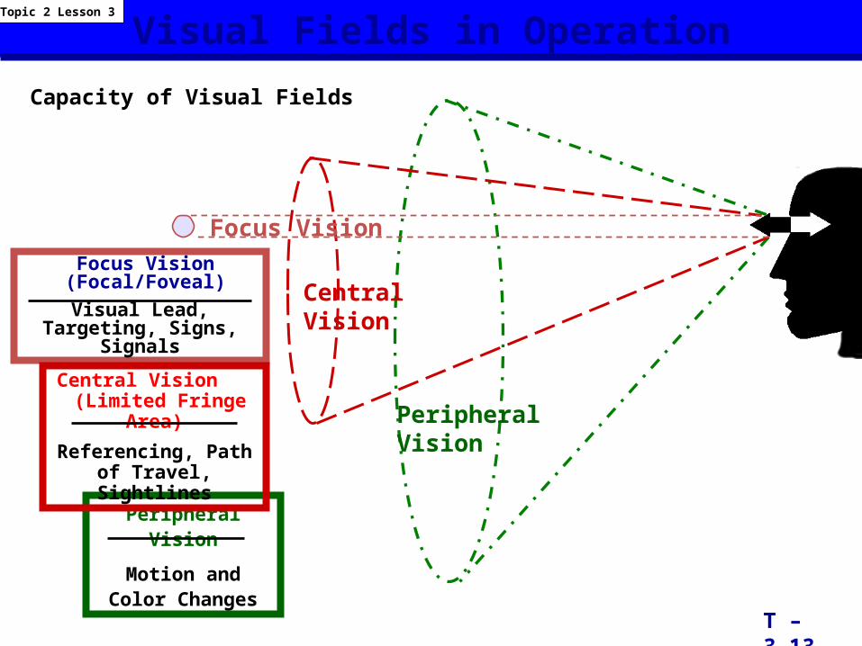
Capacity of Visual Fields
Focus Vision
Central Vision
Peripheral Vision
Peripheral Vision
Motion and Color Changes
Focus Vision (Focal/Foveal)
Visual Lead, Targeting, Signs, Signals
Central Vision (Limited Fringe Area)
Referencing, Path of Travel, Sightlines
Visual Fields in Operation
T – 3.13
Topic 2 Lesson 3
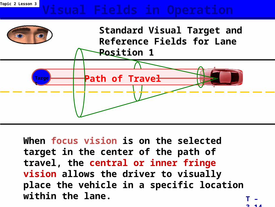
Visual Fields in Operation
Path of TravelTarget
Standard Visual Target and Reference Fields for Lane Position 1
When focus vision is on the selected target in the center of the path of travel, the central or inner fringe vision allows the driver to visually place the vehicle in a specific location within the lane.
T – 3.14
Topic 2 Lesson 3
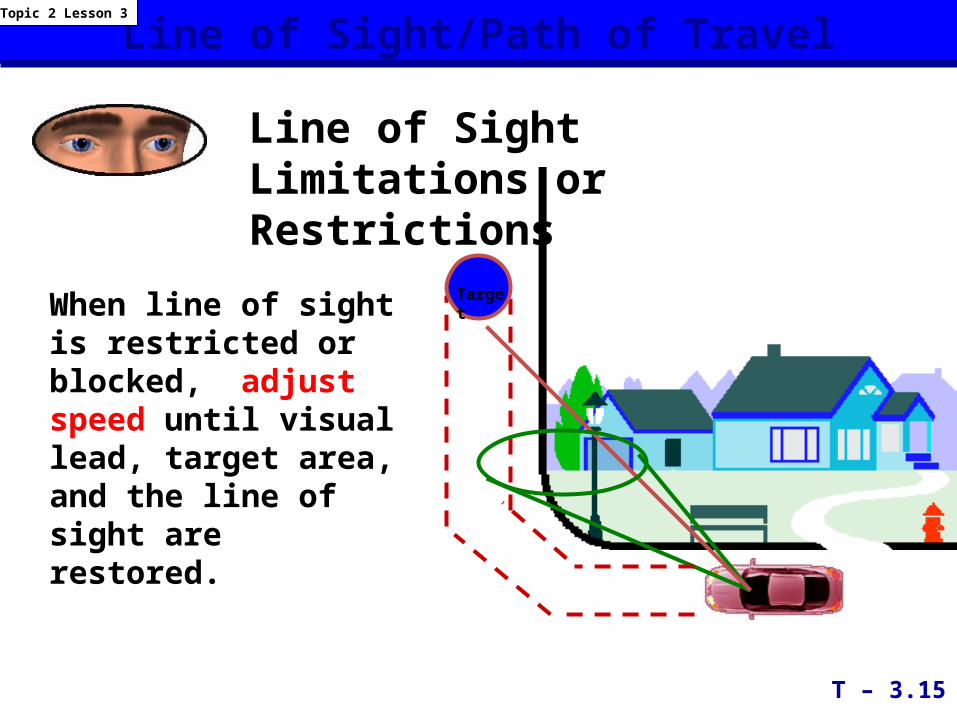
Line of Sight/Path of Travel
Line of Sight Limitations or Restrictions
When line of sight is restricted or blocked, adjust speed until visual lead, target area, and the line of sight are restored.
T – 3.15
Topic 2 Lesson 3
Target
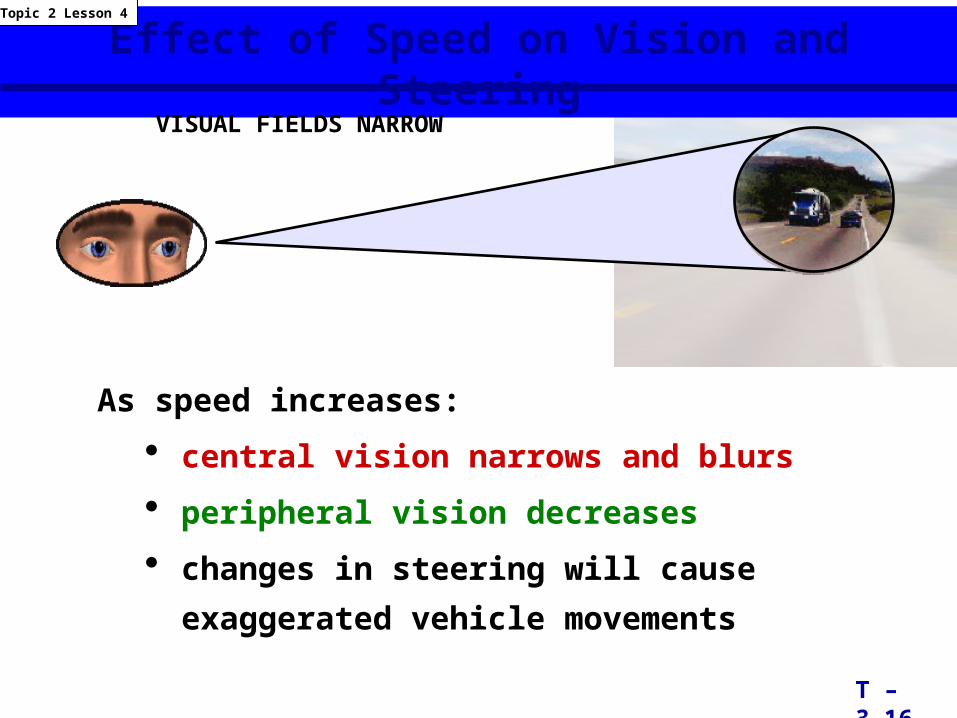
Effect of Speed on Vision and Steering
As speed increases:
• central vision narrows and blurs
• peripheral vision decreases
• changes in steering will cause exaggerated vehicle
movements
VISUAL FIELDS NARROW
T – 3.16
Topic 2 Lesson 4
Effect of Speed on Vision
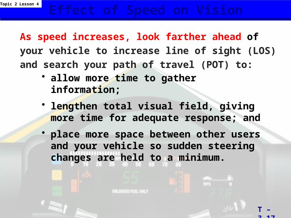
• allow more time to gather information;
• lengthen total visual field, giving more time for adequate response; and
• place more space between other users and your vehicle so sudden steering changes are held to a minimum.
As speed increases, look farther ahead of your vehicle to increase line of sight (LOS) and search your path of travel (POT) to:
T – 3.17
Topic 2 Lesson 4
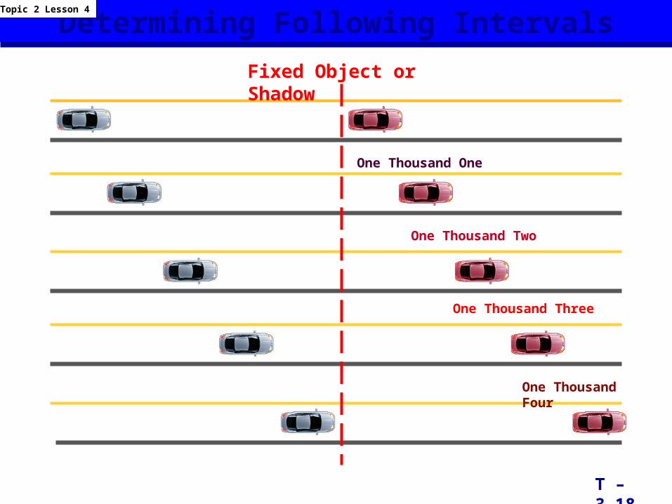
Determining Following IntervalsFixed Object or Shadow
One Thousand One
One Thousand Two
One Thousand Three
One Thousand Four
T – 3.18
Topic 2 Lesson 4
Time, Speed, and DistanceTopic 2 Lesson 4
T – 3.19
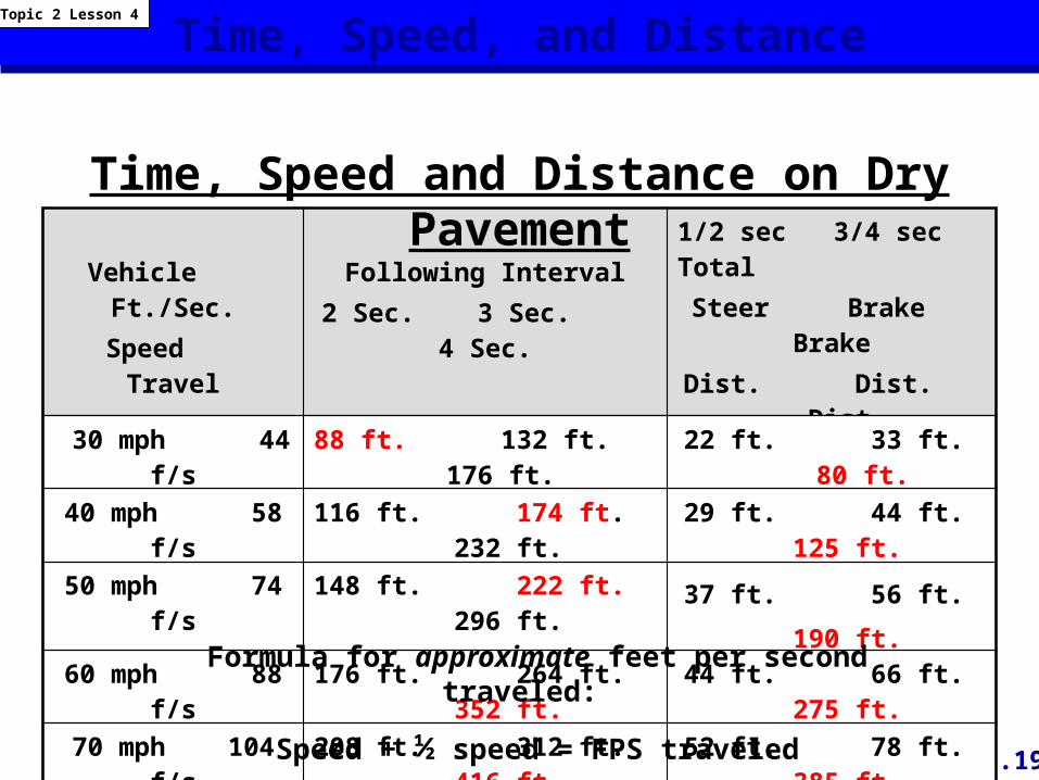
Vehicle Ft./Sec.Speed Travel
Following Interval2 Sec. 3 Sec. 4 Sec.
1/2 sec 3/4 sec TotalSteer Brake BrakeDist. Dist. Dist.
30 mph 44 f/s 88 ft. 132 ft. 176 ft. 22 ft. 33 ft. 80 ft.
40 mph 58 f/s 116 ft. 174 ft. 232 ft. 29 ft. 44 ft. 125 ft.
50 mph 74 f/s 148 ft. 222 ft. 296 ft. 37 ft. 56 ft. 190 ft.
60 mph 88 f/s 176 ft. 264 ft. 352 ft. 44 ft. 66 ft. 275 ft.
70 mph 104 f/s 208 ft. 312 ft. 416 ft. 52 ft. 78 ft. 385 ft.
Time, Speed and Distance on Dry Pavement
Formula for approximate feet per second traveled:
Speed + ½ speed = FPS traveled
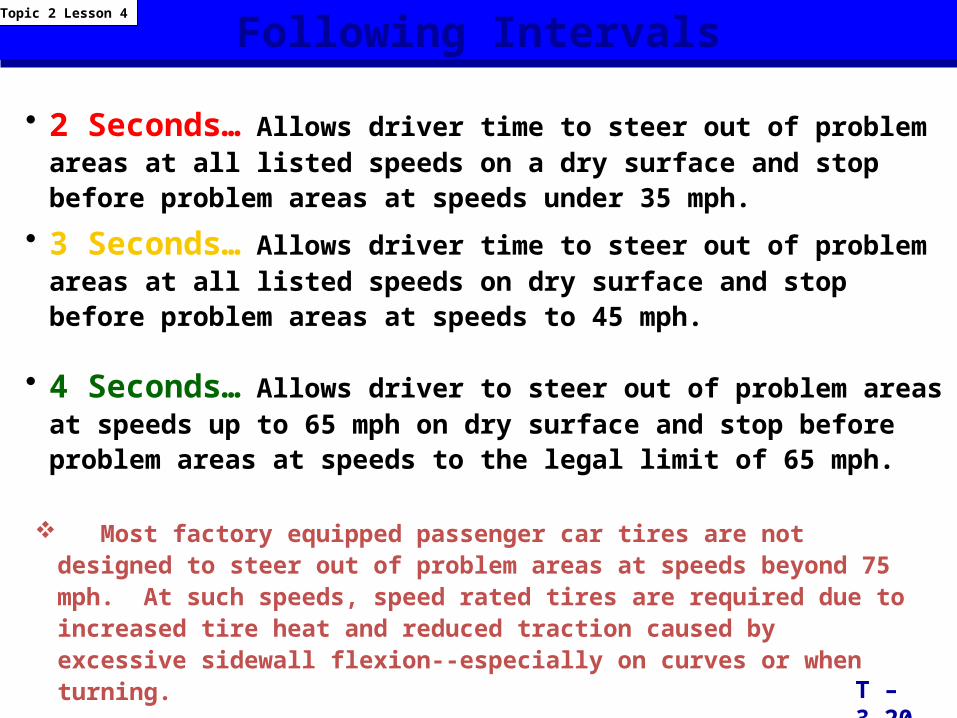
Following Intervals
• 2 Seconds… Allows driver time to steer out of problem areas at all listed speeds on a dry surface and stop before problem areas at speeds under 35 mph.
• 3 Seconds… Allows driver time to steer out of problem areas at all listed speeds on dry surface and stop before problem areas at speeds to 45 mph.
• 4 Seconds… Allows driver to steer out of problem areas at speeds up to 65 mph on dry surface and stop before problem areas at speeds to the legal limit of 65 mph.
T – 3.20
Topic 2 Lesson 4
Most factory equipped passenger car tires are not designed to steer out of problem areas at speeds beyond 75 mph. At such speeds, speed rated tires are required due to increased tire heat and reduced traction caused by excessive sidewall flexion--especially on curves or when turning.
Space Management System
• S earch• E valuate• E xecute• i n• T ime
Topic 2 Lesson 4
T-3.20a
Good Drivers Develop a Space Management System