Embed Size (px)
Citation preview

1 Hydrology for Urban Stormwater Drainage
Learning objectives: After completing this section, the student should know
- Hydrological processes relevant to urban storm drainage - Impacts of urbanization on hydrological processes and on surface runoff - Various methods to mitigate adverse hydrological impacts of urbanizations - The important aspects including structural and nonstructural measures for flood and
water quality control that need to be given attention in urban development planning - Basic concepts in catchment modelling
1.0 Introduction In this chapter, processes in the hydrological cycle relevant to urban stormwater drainage are briefly discussed first and then, impacts of urbanization on the hydrological processes and various approaches to mitigate adverse impacts are discussed. Urbanization is essentially characterized development of habitats and associated infrastructure facilities required for economic and social activities necessary for livelihood of growing population in the area concerned. Thus, urbanization brings changes in land use with construction of buildings, roads, parks and other facilities, and increases supply of water for consumptive use and release of wastewater. The natural hydrological processes that prevail in the area are therefore seriously affected due to urbanization.
1.1 Introduction to hydrological processes The hydrologic cycle is the circulation of water through the hydrosphere which extends to about 14 km to the atmosphere and about 1 km into the earth crust. The hydrological cycle has various components as shown in Figure (1.1) and there is a continuous interchange of water among these different components of the cycle. Water is driven in the cycle by solar energy directly and indirectly, by Coriolis forces and gravitational and capillary forces. However, the total mass of water in the hydrological cycle remains constant. As shown in Figure (1.1), water evaporates from the land surface, ocean, inland water bodies, vegetation enters as vapour into the atmosphere. Water vapour is transported to higher altitudes in the atmosphere until it condenses and forms clouds and eventually falls on the earth by

precipitation. Precipitation can be in the form of rainfall, snowfall or in other forms. Precipitated water may be intercepted by vegetation, may reach the land and flows as overland flow. Overland flow discharges into the streams and then to lakes or to the ocean. Some water may infiltrate into the ground, flows as subsurface flow, percolates to recharge deep groundwater. This groundwater may emerge as springs or seep into the water bodies. From all the water in the hydrological cycle about 96.5 percent is in the oceans, 1.7 percent is in the polar ice, 1.7 percent is in the form of groundwater and only the remainder which is 0.1 percent is in the surface and atmospheric water systems. The estimated water quantities in different components of the hydrological cycle are given in Table 1.1. Although the percentage of water in the surface and atmosphere is relatively small, there is a large quantity of water in them. Also, the hydrologic processes involved in the surface and atmospheric water systems are enormous and vibrant, and have a vast effect on the earth environment.
Imperviousstrata
Soil moisture
Subsurfaceflow
Groundwater flow
Watertable
Infiltration
Groundwater outflow
38 Surface outflow
424 Evaporation from ocean
Evaporation and evapotranspiration
61 Evaporation from land
39 Moisture over land
385precipitation
on ocean
100Precipitation on land
Surfacerunoff
Fig. 1.1 Hydrologic cycle

Table 1.1 Water quantities in different components of the hydrologic cycle
Item Volume (km3) Percent of water Oceans 1,388,000,000 96.5 Ground water
Fresh Saline
10,530,000 12,870,000
0.76 0.93
Soil moisture 16,500 0.0012 Polar ice 4,023,500 1.7 Other ice and snow 340,600 0.025 Lakes Fresh Saline
91,000 85,400
0.007 0.006
Marshes 11,470 0.0008 Rivers 2,120 0.0002 Biological water 1,120 0.0001 Atmospheric water 12,900 0.001 Total of water 1,385,984,610 100
Although all processes in the hydrological cycle are equally important, only the hydrological processes relevant to generation and flow of surface water that require thorough understanding for the subject of storm water drainage are discussed here.
1.1.1 Precipitation
Precipitation and evaporation are the hydro-meteorological processes in the atmosphere that interact with surface water. Precipitation is responsible for depositing the fresh water on the earth. Approximately 505,000 km3 of water falls as precipitation each year, 398,000 km3 of it over the oceans. Given the earth's surface area, that means the globally-averaged annual precipitation is 990 millimeters. Much of the water precipitated on the land surface is derived from moisture evaporated from the oceans and transported by atmospheric circulation.
The pattern of atmospheric circulation has three cells in each hemisphere as shown in Fig. 1.2. In the tropical cell, heated air ascends at the equator, proceeds toward the poles at upper levels, loses heat and descends toward the ground at latitude of 30 deg. In the polar cell, air rises at 60 deg and flows toward the poles at upper levels then cools and flows back to 60 deg near the earth’s surface. The middle cell is driven frictionally by the other two; its surface air flows toward the pole, producing westerly air flow in the mid-latitudes.

The main forms of precipitation include rain, snow, hail and sleet and it occurs when the water vapour in the atmosphere condenses and falls to the earth. The process requires saturation of the air mass by the processes of decreasing its temperature or by increasing the concentration of water vapour or by both together. The main mechanisms of adding more water vapour into air masses are by daytime evaporation water from the water bodies, evapotranspiration from plants and by wind convergence into areas of upward motion. The cooling of air masses and condensation of water vapour happens when they are lifted to higher altitudes in the atmosphere. The three main mechanisms of air mass lifting are frontal lifting, where warmer air is lifted over cooler air by frontal passage; orographic lifting, where air masses rises to pass over a mountain, and convective lifting where air moves upward due to instabilities in the air columns. Also, upward motion of the outgoing air masses at a cylcone which happens due to convergence of air masses on low pressure zone at lower elevation, leads to cooling and condensation of water vapour. a) Frontal precipitation Frontal precipitation occurs when a warm air mass, moved by wind currents and atmospheric pressure gradients, overtakes and rises above a cooler air mass. The rising of the warm, moisture-laden air to a higher altitude causes it to cool and the water vapour condenses. The precipitation from this process often extends over large areas, interface between the warm and cool air masses is called a warm front.
Tropical cell
Middle cell
Polar cellN pole
Easterlies
Low pressure60 N0
WesterliesHigh pressure
30 N0NE trade winds
SE trade winds 30 S0
High pressureWesterlies
Low pressure60 S0
Easterlies
S pole
Stratosphere
Ionosphere
Equ
ator
Dol
drum
s
Tropicaltropopause
Troposphere
Polartropopause
Fig 1.2 Pattern of atmospheric circulation

A cold front occurs when a cold air mass overtakes a warmer one and displaces the warm air upwards. Again, the rising and cooling of the warm air is what causes condensations to occur. Unlike warm fronts, the precipitation arising from a cold front is frequently spotty and often covers relatively small area. b) Cyclonic precipitation A cyclone is a region of low pressure into which air flows from surrounding higher areas. Flow around the low pressure centre moves in a counterclockwise direction in the northern hemisphere and in a clockwise direction in the southern hemisphere due to Coriolis forces. As air masses converge on the low pressure area, the incoming mass of air must be balanced by an outgoing one. Because air is entering from all directions horizontally, the outgoing air has no choice but to move vertically upward. Precipitation of this type is closed cyclonic precipitation. c) Convective precipitation Convective precipitation is caused by different heating of an air mass. It takes place in small, localized areas of a few square kilometers. This may occur in urban areas or during summer months when air near the ground surface becomes heated and rises with respect to the cooler surrounding air. This rise can be quite rapid and often results in thunderstorms. d) Orographic precipitation Orographic precipitation occurs when an air mass is forced by topographic barriers to higher altitude where the temperature is cooler. This type of precipitation is common in mountainous regions where air currents are forced up over the tops of the mountains by wind movement. When the air rises to a cooler altitude, condensation occurs. Orographic precipitation can be quite pronounced on the windward side of a mountain range while there is often a relatively little precipitation on the leeward side.
Changes of precipitation due to global warming
Mean surface temperature anomalies during the period 1999 to 2008 with respect to the average temperatures from 1940 to 1980.
Increasing temperatures tend to increase evaporation which leads to more precipitation. As average global temperatures have risen, average global precipitation has also increased. Precipitation generally increased over land north of 30°N from 1900 through 2005 but has declined over the tropics since the 1970s. Globally there has been no statistically significant overall trend in precipitation over the past century, although trends have varied widely by region and over time. Eastern portions of North and South America, northern Europe, and northern and

central Asia have become wetter. The Sahel, the Mediterranean, southern Africa and parts of southern Asia have become drier. There has been an increase in the number of heavy precipitation events over many areas during the past century, as well as an increase since the 1970s in the prevalence of droughts—especially in the tropics and subtropics.
1.1.2 Interception During precipitation, the leaves and stems of vegetation, buildings, etc capture some of the precipitation before it reaches the ground surface. This is termed as interception and the intercepted water is dissipated by evaporation during the dry weather after rainfall. Interception depends on the land cover (vegetation types, density) cover and can be significant fraction of the annual precipitation ranging up to about 30 percent.
1.1.3 Evaporation and Evapotranspiration
Evaporation which is the vaporization of water from a water surface depends on the supply of heat energy to provide latent heat to produce vapour and transport of the vapour away by the wind. The measured pan evaporation data provide the best indication of nearby open water evaporation. A measured value of pan evaporation is multiplied by a pan factor in the range of 0 to 1 (usually taken as 0.7) to convert it to open water evaporation value.
Evapotranspiration (ET) is the evaporation from land surface and transpiration from vegetation. It depends on the availability of moisture in the evaporative surface other than the above two factors governing the evaporation. The evaporation component of ET includes direct evaporative loss from the soil surface, depression storages and intercepted water. Transpired water is that which is used by vegetation and subsequently lost to the atmosphere as vapor. The water generally enters the plant through the root zone, is used for various biophysiological functions including photosynthesis, and then passes back to the atmosphere through the leaf stomates. Transpiration will stop if the vegetation becomes stressed to the wilting point, which is the point in which there is insufficient water left in the soil for a plant to transpire, or if the plant to atmosphere vapor concentration gradient becomes prohibitive to plant physiological processes.
The calculations of rate of evapotranspiraton are made using the pan evaporation with adjustments to account for the condition of the vegetation and soil. For a given climatic condition, basic rate is the reference crop evaporation defined as the rate evapotranspiraton from an extensive surface of 8 cm to 15 cm all green grass cover of uniform height, actively growing, completely shading the ground and not short of water.

The potential evapotranspiration of another crop growing under the same conditions as the reference crop is calculated by multiplying the reference crop evaportaspiration by a crop coefficient. Crop coefficient changes with the stage of growth of the crop.
Actual evapotranspiration (AET) is the quantity of water that is actually removed from a surface due to the processes of evaporation and transpiration. AET is found by multiplying the potential evapotranspiration by a soil coefficient.
1.1.4 Infiltration The process of penetrating of water from the ground surface under gravity is called infiltration. Many factors influence the infiltration rate. It mainly depends on condition of soil surface, existing land cover, properties of soil beneath. Properties of soil include porosity, hydraulic conductivity and existing moisture content of the soil. These properties significantly vary with time and space, and therefore the infiltration process is a complex process to describe mathematically. In unsaturated soil, that is when the void spaces in soil are only partially filled with water, the water is attracted and kept bonded to the particle surfaces through surface tension and a soil suction force is present. The energy possessed by unit weight of water due to suction force is referred to as suction head. The suction head varies with the moisture content and it diminishes as the soil gets saturated. The hydraulic conductivity, on the other hand, increases with the increase of moisture content (Fig 1.3).
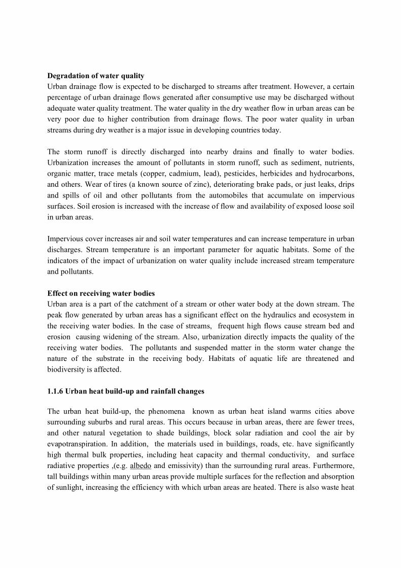
1.1.5 Subsurface flow Subsurface flow which occurs as lateral flow beneath the land surface is a major component in the hydrological cycle. Subsurface water zones and processes are shown in Fig. 1.4. The water stored in the form of soil moisture in unsaturated or saturated soil laterally flows under energy gradient. The subsurface flow finally leads to a stream at a depression and subsurface flow contributes for the base flow present in streams during dry weather periods. During dry weather period with no infiltration from other than the surface water storages, the source for subsurface flow is the stored water in the catchment in the form of soil moisture. The subsurface flow released into streams and evapotranspiration gradually reduces the subsurface storage. In turn, the depleting soil moisture storage reduces the subsurface flow into the streams. Subsurface flow velocities and discharge can be estimated by the application of Darcy’s law.
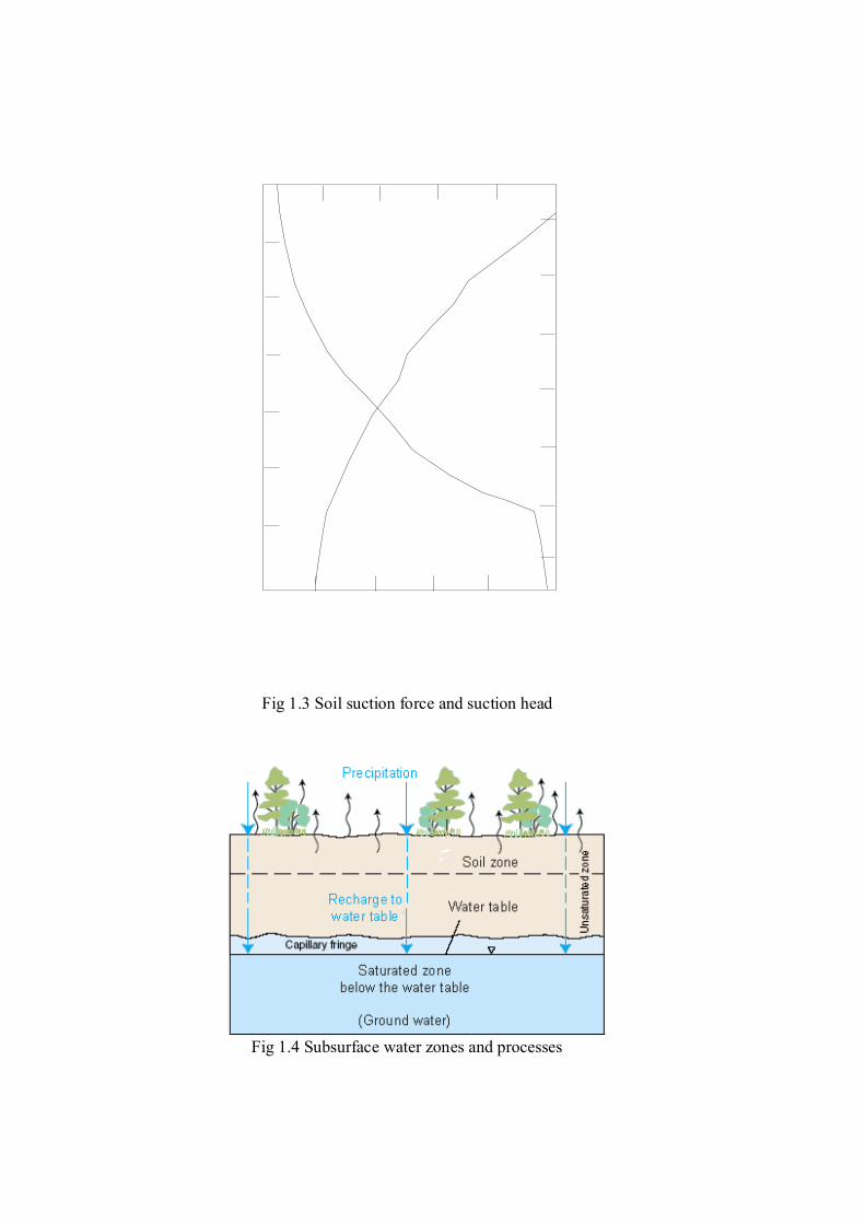
Fig 1.4 Subsurface water zones and processes
Fig 1.3 Soil suction force and suction head

1.1.6 Surface water flow Inland surface water is a major part in the hydrological cycle. Surface water flows are caused during precipitation as excess over infiltration, and due to releases of water after consumptive uses from houses, industries and irrigation, discharge from springs, and secretion (or exfiltration) from saturated and unsaturated soil as base flow. Surface water flow appears as overland flows during precipitation and for short period after precipitation, etc. and as channel flows in drains, streams and rivers. As the rainfall continues, the rainfall intensity exceeds the infiltration capacity of the soil and excess water begins to pond on the land surface. The ponded water fills depressions and potholes in the ground surface and, also remain attach to the surface by surface tension. Depression storages are depleted by infiltration and evaporation. It is only after filling these depression storages that water starts to flow downstream as overland flow. First, overland flow concentrates into rill flow, and then rill flow concentrates into gully flow and stream flow. The overland flow continues to flow downstream in the catchment slope until it is discharged to a drain or a stream. However, overland flow may be intercepted within the catchment by natural depressions in ground or manmade storage facilities and detained or retained. When a rainfall of intensity (i) occurs on a plain sloping ground of a unit area with an infiltration rate (f), generates a runoff of equivalent to the excess precipitation over infiltration (i-f). The same may be extended to estimate the overland flow generated from a catchment slope by multiplying the excess precipitation over infiltration over by the catchment area. This type of overland flow is known as Hortonian overland flow. When the soil profile is saturated, there is no infiltration and saturation overland flow occurs. Stream flow hydrograph Stream flow is formed by both overland flow and subsurface flow. Stream flow hydrograph gives the discharge at a location of a stream as a function of time. It may be used to represent variation of monthly stream flow at the location over a period of several years or it may be used to represent the response of the catchment at the location during a rainfall event hourly rainfall.

Figure 1.5 shows a typical stream flow hydrograph at a location in a stream during a rainfall. Prior to the beginning of the rainfall, base flow is gradually diminishing (segment AB). Direct runoff begins at B, peaks at C and ends at D. Segment DE follows as base flow recession begins again. Tp, called time of concentration, is the time taken for flow in the catchment to concentrate to the location . Time of concentration implies that during this period of time the flow rate gradually increases until rainfall from the entire catchment has had time to travel to the outlet and contributing to the flow at the location. The characteristics of a catchment have two basic effects on the shape of the hydrograph at the outlet of the watershed. The geometric characteristics including size, shape, hydraulic length, slope and drainage pattern these are reflected by the time of concentration, depression storages, runoff volumes.
Figure 1.5 Typical stream flow hydrograph

1.2 Impacts of urbanization on surface and subsurface hydrology Urban areas concentrate population and production and provide some obvious advantages over rural settlements. Urban community is served with the facilities of all kinds mostly at door step at a cheaper price compared to rural community. In particular, the service providers have larger and concentrated customer population in urban areas to enable them to maintain lower specific cost for the provision of potable water supplies, sewers and drains, garbage collection, telecommunication, transportation, health, educational and emergency services. Urbanization accompanies the introduction of vast impervious areas, efficient hydraulic conveyance systems and supply of large volumes of pipe water resulting changes to an urban setting to dramatically alter the surface and subsurface hydrology. Urbanization is also responsible for increase of discharging pollutants to natural water bodies. The concentration of domestic, commercial and industrial wastes causes major environmental and health problems for the inhabitants. Principal phases of the urban water cycle are given in Fig. 1.6.

Fig 1.6 Movement of water in urban environment Source: Technical Documents in Hydrology , No. 50, UNESCO

1.2.1 Changes forced to hydrological setting by urbanization In a pre-urbanized catchment, naturally evolved surface flow drainage systems and hydrological processes prevail. Natural storage in a catchment is being made available by the effects of infiltration, vegetation wetting, interception and depression storage. Urbanization affects the hydrological processes through the changes introduced to the parameters governing the processes (boundary conditions of the system). Reduced interception
With the removal of vegetation in the catchment, interception of precipitation is reduced allowing higher volume of precipitation to reach the ground. Increased imperviousness Changes in land use by the construction of buildings, roads, parking areas and other facilities in the process of urbanization increases the impervious proportion in the land area. With the urbanization, vegetation cover is drastically reduced. Faster conveyance system Water drainage system is improved by introducing lined canals, buried sewers to efficiently drain water out from the urbanized area to avoid inconvenience to the public. Changes in hydraulic efficiency of storm water collection systems with artificial channels, storm sewers increase the velocity of flow. In an efficient manner, stormwater from roofs are conveyed to storm drains through gutters and downpipes, curbs and gutters are designed to convey storm water away from the road surface to storm drains. Thus drainage systems quickly convey the runoff directly into receiving waters compared to pre-urbanized setting. The surface topography is altered in open areas to avoid water logging. The retention period of water is reduced. Increased water supply for consumptive use
Large volumes of piped water are supplied for municipal, industrial and other consumptive uses in an urban area. Most of this water is released as wastewater after consumptive use. Sources for supplying this water demand can be various; from a catchment outside urban area, from the head waters of catchment of the urban area or from the area itself. If water is supplied from a source outside the catchment, it means there is more water now in the catchment (urban area) the than before. If the water is from the urban area itself, water abstraction can be from the subsurface storages or from the surface water flow. Increased water supply changes the hydrology in the area, and the effect can be significant specially during the dry weather period.

Release of wastewater (urban drainage flows) and sewer systems Water is consumed all over the urbanized area and released as wastewater after use. Wastewater is generated from residences, business and services (e.g. restaurants), industries. Theses wastewater sources are spatially distributed and the discharges are time-varying. The facility for wastewater drainage from urban areas is generally provided in two ways: separate sewer system for wastewater from storm sewers or as combined sewer system. In separate sewer systems, wastewater is collected and treated separately and treated water is discharged sometimes to surface water bodies. In combined sewer systems, wastewater and stormwater are drained together and released to surface water bodies or main stormwater drains after treatment. Overflow under extreme conditions are however directed to main stormwater drains bypassing the treatment facilities. The changes to diurnal and seasonal flow patterns prevailed in the streams in the area and the downstream are discussed later. Increase in material consumption and commercial activities Population increase leads to increase in consumption of material and increase of commercial activities. Therefore, there is an increase in the generation of municipal and industrial wastewater, and solid waste in the catchment. The sources of stormwater pollutants are diffuse and highly variable.
1.2.2 Urbanization effect on surface water flow Changes to the flood hydrograph Increase in runoff The volume of water available for runoff increases because of the increase in the impervious cover provided by roofs of buildings, streets, paved parking lots, lined drains which reduce the amount of infiltration. Before urbanization much of the rainfall is absorbed by the surrounding vegetation, soil and ground cover. The runoff coefficient is a measure of the amount of rainfall that is converted to runoff or storm runoff generation. As the percentage of watershed imperviousness increases, the runoff coefficient increases with urbanization.

Decrease in time of concentration Changes in hydraulic efficiency of storm water collection systems with artificial channels, storm sewers increase the velocity of flow. In an efficient manner, stormwater from roofs are conveyed to storm drains through gutters and downpipes, storm water from road surfaces are conveyed to storm drains through curbs and gutters. Thus, drainage systems convey the runoff quickly into receiving waters compared to pre-urbanized setting. The retention period of water is reduced and time concentration of flow at a stream section is drastically reduced.
Figure 1.7 Changes in the flood hydrograph Figure 1.7 shows the typical change brought to flood hydrograph at the outlet of an area due to urbanization. The hydrograph depicts the increase in flood peak due to increased runoff and the

reduced time of concentration. The total volume of discharge is increased due to reduction in infiltration (increase in the runoff coefficient). The hydrograph indicates steeper limbs, i.e. the rapid increase and drop in discharge, and this steepness of the hydrograph implies the increase in flash floods brought by urbanization. Floods in urban conditions occur both on urbanized surfaces (streets, parking lots, yards, parks) and in small urban creeks that deliver water to large water bodies. Urban floods are flashy. Furthermore, flooding is aggravated due to lack of maintenance of drainage facilities due to clogging the drainage system and sediments and solid wastes/debris transported with the stormwater. Increase in urban drainage flow Water supplied to the urban area is discharged to the drainage system after consumptive use and creates a considerable drainage flow in the sewers. The urban wastewater flow has variations in daily, weekly, monthly, and annually scales. The typical diurnal variation in urban drainage flows in a residential area takes the pattern shown in Figure 1.8. There is relatively little sanitary flow at night, increased flow during the early morning hours as people wake up and prepare for the day, decreased flow during the middle of the day, and, finally, increased flow again in the early evening as people return home. Figure 1.9 shows the difference in drainage flows between residences and industries. Weekly variation is mainly due to usage pattern of water that often differ during weekdays and weekends. Seasonal variations in urban wastewater flows is related to changes in climatic variables, such as temperature and precipitation, and also to the changing habits of customers, such as travel and other activities occurring in the summer. Higher drainage flows are evident during summer season compared to winter season. Changes in dry weather flow An increase in impervious surface decreases the amount of rainfall available for infiltration. The efficient hydraulic conveyance system reduces ponding time and the detention time of water and thus reduces infiltration. The groundwater recharge is therefore greatly reduced and the subsurface flow is drastically reduced. As a result, streams will lose the potential source of water, and base flow from the catchment reduces. Dry weather flow in an urbanized catchment depends not only on the base flow but also on the contribution from wastewater flows after consumptive use or urban drainage flow. The urban

drainage flow discussed above will enter into the drains and finally to the streams. Drainage flow contribution has a significant share in the dry weather flow.
Figure 1.8 Diurnal variation in urban drainage flows
Fig 1.9 Difference of drainage flows in residences and industries
Degradation of water quality Urban drainage flow is expected to be discharged to streams after treatment. However, a certain percentage of urban drainage flows generated after consumptive use may be discharged without adequate water quality treatment. The water quality in the dry weather flow in urban areas can be very poor due to higher contribution from drainage flows. The poor water quality in urban streams during dry weather is a major issue in developing countries today. The storm runoff is directly discharged into nearby drains and finally to water bodies. Urbanization increases the amount of pollutants in storm runoff, such as sediment, nutrients, organic matter, trace metals (copper, cadmium, lead), pesticides, herbicides and hydrocarbons, and others. Wear of tires (a known source of zinc), deteriorating brake pads, or just leaks, drips and spills of oil and other pollutants from the automobiles that accumulate on impervious surfaces. Soil erosion is increased with the increase of flow and availability of exposed loose soil in urban areas. Impervious cover increases air and soil water temperatures and can increase temperature in urban discharges. Stream temperature is an important parameter for aquatic habitats. Some of the indicators of the impact of urbanization on water quality include increased stream temperature and pollutants. Effect on receiving water bodies Urban area is a part of the catchment of a stream or other water body at the down stream. The peak flow generated by urban areas has a significant effect on the hydraulics and ecosystem in the receiving water bodies. In the case of streams, frequent high flows cause stream bed and erosion causing widening of the stream. Also, urbanization directly impacts the quality of the receiving water bodies. The pollutants and suspended matter in the storm water change the nature of the substrate in the receiving body. Habitats of aquatic life are threatened and biodiversity is affected. 1.1.6 Urban heat build-up and rainfall changes
The urban heat build-up, the phenomena known as urban heat island warms cities above surrounding suburbs and rural areas. This occurs because in urban areas, there are fewer trees, and other natural vegetation to shade buildings, block solar radiation and cool the air by evapotranspiration. In addition, the materials used in buildings, roads, etc. have significantly high thermal bulk properties, including heat capacity and thermal conductivity, and surface radiative properties ,(e.g. albedo and emissivity) than the surrounding rural areas. Furthermore, tall buildings within many urban areas provide multiple surfaces for the reflection and absorption of sunlight, increasing the efficiency with which urban areas are heated. There is also waste heat
from automobiles, air conditioning, industry.roof and paving materials. These reasons cause both surface temperature and overall ambient air temperature in an urban area to rise.
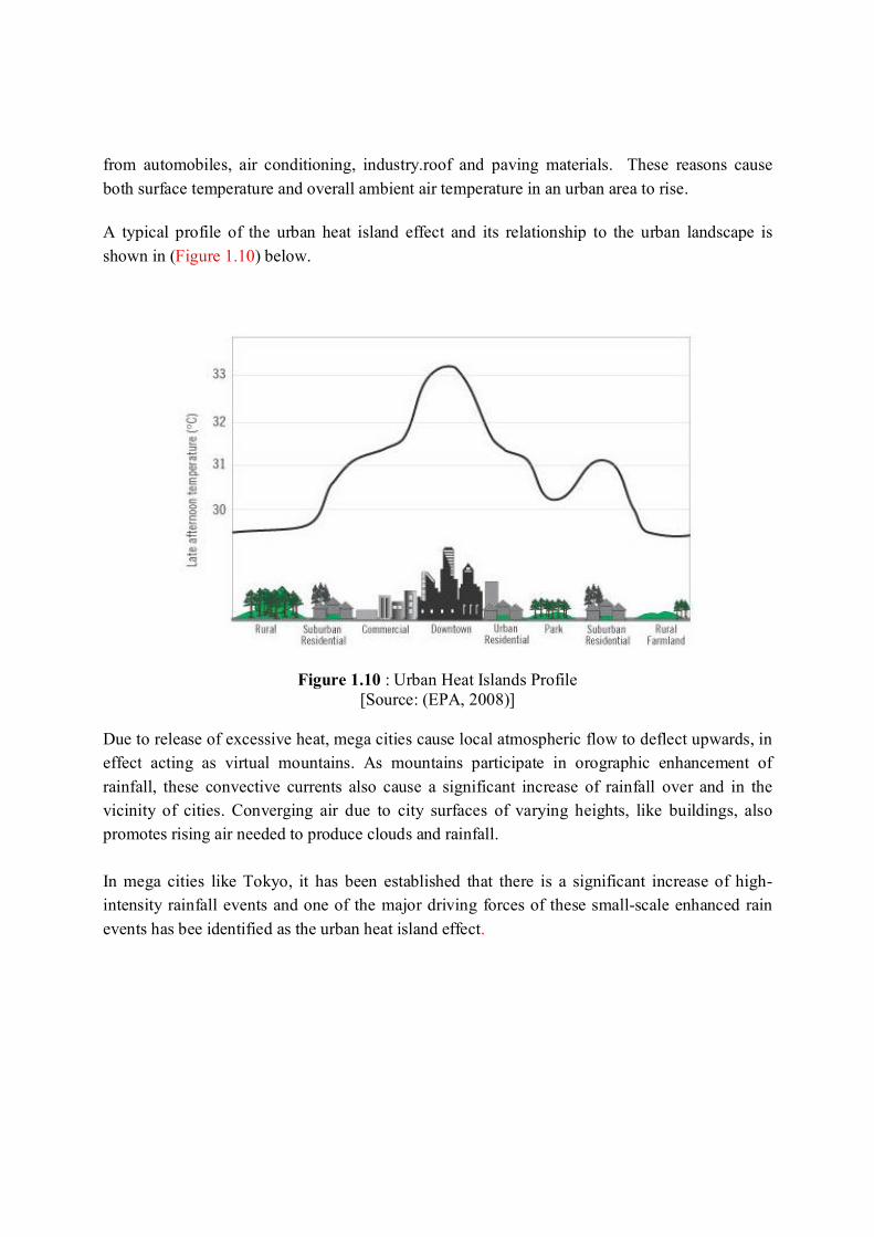
A typical profile of the urban heat island effect and its relationship to the urban landscape is shown in (Figure 1.10) below.
Figure 1.10 : Urban Heat Islands Profile [Source: (EPA, 2008)]
Due to release of excessive heat, mega cities cause local atmospheric flow to deflect upwards, in effect acting as virtual mountains. As mountains participate in orographic enhancement of rainfall, these convective currents also cause a significant increase of rainfall over and in the vicinity of cities. Converging air due to city surfaces of varying heights, like buildings, also promotes rising air needed to produce clouds and rainfall. In mega cities like Tokyo, it has been established that there is a significant increase of high-intensity rainfall events and one of the major driving forces of these small-scale enhanced rain events has bee identified as the urban heat island effect.

1.3 Mitigation of adverse impacts of urbanization Mitigation of adverse hydrological impacts of urbanization is essentially requires a multi-disciplinary approach through structural and non-structural measures. The hydrological impacts affect the socio-economic and environmental conditions in the area and vise-versa. The civil engineering components fall mainly to the structural measures and those alone fails to mitigate the adverse impacts on hydrological environment. Non-structural measures of mitigation of urbanization impacts on hydrology include measures that do not involve constructions, such as conducting awareness building among the population about the consequences of ad hoc developments on development projects, preparedness for facing floods, introduction of legislations, introduction of environmental impact assessment, etc that contribute directly towards reducing losses of life and damage to property. Structural and non-structural measures must be integrated to the planning and development of urban areas to avoid the need for an isolated approach to solve urban drainage problems. Preventive actions for hydrological impacts are always simpler and cost effective compared to corrective actions. Some suggested actions include: maintaining the natural rainfall-runoff ratios, protecting hydrological sensitive areas, sediment sources, and sensitive habitat areas, minimize and hydraulically disconnect impervious areas, such as rooftops, rain gutters, parking lots and roads, minimize topography changes and soil compaction, cluster development in less sensitive areas, integrate flood control and water quality control structures into the landscape. Stormwater is a significant source of pollution, and therefore concepts of source control, flow attenuation and treatment in natural and artificial biological systems are important. 1.3.1 Non-structural measures
Non-structural measures applicable are greatly area specific and depend on the socio-economic, environmental policies of the governing local authorities. Nevertheless, the new urban development projects can be enforced with conditions to maintain natural drainage, minimize the impervious areas to be created, provide sufficient areas for infiltration and storm water storage. Legislation that needs to be enacted in order to provide legal basis for implementation of stormwater directives and programs should include provisions for:
- temporary storage of excess runoff, i.e. release of runoff during a storm is controlled by imposing mandatory storm water retention or detention facility within the premises. Building codes are introduced to include storm water storage facilities, infiltration trenches, etc..
- provisions for floodplain zoning and regulation, i.e. to regulate land use changes, some areas will be prohibited for developments and left out for flood control.

- provisions for flood-proofing of buildings, i.e. buildings are required to adopt flood proofing techniques to coop with floods
- stormwater pollution control, i.e. source is controlled by imposing quality standards for wastewater and solid waste disposals in urban environments, to adapt devices to control the discharges, to improve the quality at the premises itself by owners before releasing to the public facility such as storm water drains
- provisions for development of a compatible and coordinated stormwater drainage system.
1.3.2 Structural measures The traditional prescriptions for urban drainage are the rapid removal of surface water through artificial drainage systems, straightening and channelizing the existing streams. However, as discussed in Section 1.2.2, these practices shorten the time of concentration and increases the flash floods and peak discharges at the downstream. Therefore urban drainage solutions require to adopt rapid removal structures and retarding structures and onsite techniques to minimize runoff generation and to increase infiltration. The traditional “efficient conveyance” approach is shifted gradually towards the “water storing” approach, focusing on detention, retention and recharge. In most cases the natural depressions can be used to provide storage as temporary storages or continuous storages for urban flows to relieve the drainage network and the downstream receiving bodies of excess discharges and pollutant loads. a) Flow detention and retardation structures Detention and retardation structures can be subdivided into storage type and infiltration type. Storage type structures can be on-site storage structures such as large scale detention ponds and retarding basins with a large catchment area or off-site storage structures such as small tanks or reservoirs located in residential units, parking areas, playgrounds etc. to retard stormwater discharges. The infiltration type structures include pervious pavements, infiltration trenches, ponds and inlets. Detention ponds Detention pond or retarding basin is a facility for temporary water storage to reduce the flood peaks (Fig 1.11a). When the water level in the stream rises, water spills or flows into the detention pond. When the water level in the stream recedes, water in the detention pond flows back to the stream slowly. Detention ponds are usually constructed at natural depressions. The pond may be provided with control gates and may be kept with a minimum storage to maintain aquatic life alive during low flow periods.

Retention ponds Retention pond is a reservoirs to retain water and they are not emptied after storms like in the case of detention ponds (Fig 1.11 b). There is a residence time provided for water, for pollutants and sediments to settle down on the reservoir bed. The design of capacity is based on the runoff generated from the basin due to a design storm. Sluices are designed to make control releases and spillway is provided to discharge the excess water not to damage the structure and not to inundate the upstream in case of heavy storm. Sluices are designed such away that a dead storage is provided to trap heavy metal pollutants and sediment without releasing to the downstream. On-site detention ponds These are small reservoirs or ponds provided in residential and commercial plots. These are enclosures surrounded by concrete walls to collect excess water during a storm and to release gradually to the downstream drains by a controlled outlet. Thereby, the stormwater release is regulated to reduce the flood peak downstream. In most cases open areas such as play grounds and parks are uses as on-site detention ponds. Once the water is completely released the facility is cleaned and put into normal use.
Fig 1.11 Flow detention and retention structures
a) Detention pond
b) Retention pond

b) Infiltration type devices Infiltration trenches Infiltration trenches are provided to enhance the infiltration of storm water into the ground. A trench is excavated in the ground and filled with crushed stone and top of the trench is covered by fabric to avoid sediments and debris entering into the trench. Trenches trap the stormwater and facilitates infiltration of water into the soil and recharging the groundwater. Therefore, the runoff volume is reduced. Inflow of sediment laden water will clog the trenches. Therefore, it is important to provide suitable sediment traps or settling basins at the upstream of the trenches so that sediment is removed from the water. Since the water is used to recharge the groundwater, water should be free from heavy metal pollutants. Efficiency of an infiltration trench depends on the infiltration rate. Trenches are long and narrow, excavated to a depth of about 0.5-1 m into the ground. Grass filter strips These are stripes of grassed soil surfaces introduced between the urban impervious surfaces and the storm drains to slow down and partially infiltrate runoff. This is possible when the storm water discharge can be spilled on to the strip and spread across the width of the grass strip. The velocity of the flow over the grass is small and part of the flow is infiltrated and the suspended particles in the flow are trapped within the grass strip. Grass strip should be of very mild slope and grass should be dense to avoid erosion and forming channels. The effect of grass filter strips however in reducing flood peak is negligible. Grass swales These are depressions in the grassed terrain designed to function as small unlined channels in which storm water runoff is slowed down and partially infiltrated along their course. The flow left after infiltration is conveyed to the storm drain system at the downstream. Grass swales also perform similar to grass filter strips when the slopes are small, less than 5%. Pervious pavements Pervious pavements are permeable surfaces where the runoff can pass and infiltrate into the ground. Pervious pavements facilitate peak flow reduction, ground recharge and pollution filtering. There are three types of pervious pavements: i) porous asphalt pavements ii) porous concrete pavements iii) garden blocks. The main difference to conventional pavement is that there are no fine aggregate in the mixture used in the construction. Porous layer is constructed on a granular base laid on the existing soil surface. These pavements not only reduce the flood peak but also abate the pollutants in the surface runoff.

Porous asphalt pavements are popularly used today in roads and parking areas in urban areas. Porous concrete pavements are used in open walkways and parking areas. In the gardens, for
pavements that are only used for walking garden blocks are also
used. i) porous asphalt pavements ii) porous concrete pavements iii) garden blocks
* The cost Some estimates put the cost of pervious pavements at two to three times that of conventional asphalt pavements. Using pervious pavements, however, can reduce the cost of providing larger or more stormwater Best Managerment Practises (BMPs) on site, and these savings should be factored into any cost analysis. In addition, the off-site environmental impact costs of not reducing on-site stormwater volumes and pollution have historically been ignored or assigned to other groups (local government parks, public works and environmental restoration budgets, fisheries losses, etc.). Photo courtesy of National Ready Mix Concrete Assn
* Longevity and maintenance Some pervious pavements require frequent maintenance because grit or gravel can block the open pores. This is commonly done by industrial vacuums that suck up all the sediment. If maintenance is not carried out on a regular basis, the porous pavements can begin to hold large amounts of water and cause flooding. With more advanced paving systems the levels of maintenance needed can be greatly decreased, concrete block pervious pavements requires no more maintenance than regular concrete paving as the grit between the blocks enhances the filtering properties of the pavement. Some pervious pavements products are prone to damage from misuse, such as drivers who tear up patches of plastic & gravel grid systems by "joy riding" on remote parking lots at night. The damage is not difficult to repair but can look unsightly in the meantime. Grass pavers require supplemental watering in the first year to establish the vegetation, otherwise they may need to be re-seeded. Regional climate also means that most grass applications will go dormant during the

dry season. While brown vegetation is only a matter of aesthetics, it can influence public support for this type of pervious pavements. Traditional permeable concrete paving bricks tend to lose their color in relatively short time which can be costly to replace or clean and is mainly due to the problem of efflorescence. (www.en.wikipedia.org/wiki) Infiltration ponds Infiltration ponds are similar to detention ponds but they are specifically provided to infiltrate the stormwater routed there into the soil. They are not usually provided sluices for releasing water. However, spillways and low level outlets for emergency operations are provided. The infiltration ponds are appropriate to places with pervious soils and deep water table. The disadvantage of these ponds is the possible odour problems and becoming sites for breeding of mosquitoes in tropical climates. Therefore combined detention and infiltration ponds are preferred. Infiltration inlets Infiltration inlets are draining structures that replace the gulley holes, or the uptake points for conventional storm water (Fig. 1.12). They are similar to infiltration trenches except that the bottom is also isolated from the soil. Infiltration is not the main purpose and that collected runoff is discharged to a storm drain. The purpose of the infiltration inlet is to convey the water slowly through it to retard the arrival of water into the storm sewers. The inlet needs a large cross section in the trench than in the case of a normal gulley hole.
Fig 1.12 Infiltration inlet

c) Wetlands Wetlands are shallow ponds with growing aquatic plants constructed across streams at depressions for removal of pollutants in water. They provide a detention time for the water to settle pollutants/sediments and for the aquatic plants to uptake pollutants. A low velocity has to be maintained through wetland and wetlands are effective at removing phosphorus, nitrogen compounds, metals and organic compounds, and sediments in water. However, the required surface area of the wetland is large to treat high discharges of storm water runoff.
d) Flood proofing Flood proofing is the use of permanent, contingent or emergency techniques to either prevent flood waters from reaching buildings and infrastructure facilities, or to minimize the damage from water that does get in. Fig 1.13 shows examples of flood proofing.
Fig 1.13 Examples of flood proofing

1.4 Urban catchment modeling concepts
The purpose of the urban stormwater drainage system is to convey the runoff generated from the urban area safely to a receiving water body which has assimilating capacity. The urban stormwater drainage system consists of structures designed to collect, convey, store, detain, treat and release the urban runoff. The urban runoff is contributed by the stormwater generated by precipitation to the catchment or snowmelt and urban flows. A typical urban runoff hydrograph in an urban stream is shown in Figure 1.14 .A peak flow of runoff is required to be used as design flow of the design of stormwater drainage system. It is estimated by runoff generated due to a selected storm event which is the dominant contributor and by urban flows. This design peak flow inflicts requirement of the conveyance capacities of canals and pipes, storage capacities of retention/detention basins, discharging capacities of spillways and gates, etc. in the system. Dry weather flows depends mainly on the urban flows and are specially important in the water quality aspects of the stormwater drainage system design.
0
5
10
15
20
25
30
35
40
12:00 AM 2:00 AM 4:00 AM 6:00 AM 8:00 AM 10:00 AM 12:00 PM
June 21, 2002
Average DWF = 4.8 ft /s3
Flow
, ft/
s3
Peak Flow = 38.2 ft /s3
0.00
0.05
0.10
0.15
0.20
0.25
0.30
0.35
0.40
Rai
nfal
l, in
./hr
Storm HydrographBaseflow HydrographTotal Rainfall = 0.19 in.
Figure 1.14 A typical urban runoff hydrograph

Urban catchment modeling involves simulation of hydrological processes of the urban catchment to derive runoff required for the design of appropriate stormwater drainage system. Event-based hydrologic modeling is carried out to estimate flows due to a given storm event and is the tool used for deciding design flows of system components. On the other hand, continuous hydrologic modeling is carried out to derive long-term continuous flows and to understand the long-term variations of flows. The latter is particularly useful in water quality estimations in the system. This section gives only the catchment hydrological modeling concepts and hydrological models are given in Chapter 5. 1.4.1 Hydrologic processes modelling Modeling of hydrologic processes for estimating runoff generated from the catchment for the purpose of stormwater drainage design is discussed here. Stormwater runoff generated by a rainfall event depends on the catchment characteristics and rainfall characteristics. Design requirements for urban stormwater drainage are usually specified in terms of a rainfall of certain return period.
a) Catchment and sub catchment delineation The catchment area to be drained is required to be defined based on the topography of the area. In some cases, there may be discharges into the catchment other than through gravity flow from areas outside the normal catchment. For example, there may be pumping of urban drainage flow from an adjacent catchment. The effective catchment area contributing to the catchment drainage flow includes all such contributory catchments (Figure 1.15). Drainage network in a catchment whether pre-urban or urban catchment, consists of distribution of drainage paths (drains, streams) that converge to form the main drain/stream at the outlet of the catchment concerned. Urban catchments are usually modeled not as a single catchment but as collection of subcatchments. This practice has several advantages. Distributed properties in a heterogeneous urban catchment can be taken into consideration. In relation to the design of components of urban stormwater drainage system, the design flows are required not only at the outlet of the catchment but also at the outlets of all drainage paths converging to the main stream. Also, the effect of attenuation of peak flow within the drainage network of the catchment by routing the flows discharged into the main stream (and sub-mains) at different points with time lags provides realistic distributed discharges in the network. Overland flow routing may be not necessary if a subcatchment is very small.

Figure 1.15 Subcatchments for an urban catchment b) Rainfall Analysis Rainfall characteristics important for planning and design of stormwater drainage in a catchment are rainfall intensity, temporal variation including rainfall duration and rainfall depth, spatial variation and recurrence interval of rainfall. Intensity is a measure of the quantity of rain falling in a given time (e.g. mm/hr). Duration is the period of time during which rain falls. Recurrence interval or return period of a rainfall of certain magnitude is the average length of time expected to elapse between the rainfall events of equal or greater magnitude. Intensity-Duration-Frequency Analysis Intensity-duration-frequency (IDF) curves at a location are one way of presenting rainfall data available at location by statistical analysis. Frequency refers to the probability that a storm of given magnitude will be equaled or exceeded in a given year and is equal to the reciprocal of the

return period in years. IDF curves provide average rainfall intensities corresponding to a particular return period for different durations. Typical IDF curves are given in Fig.1.16 and Fig.1.17 Generally the greater the intensity of rainfall, the shorter is the duration of rainfall. The equation of IDF curves has the form of
bt
ai
where, i = intensity (mm/hr) t = time (hour)
a and b are locality constants
http://www.state.nj.us/transportation/eng/documents/drainage/drainage.shtm
Figure 1.16 Typicall Intensity Duration Frequency Curves.

thecriticalflow.wordpress.com
Figure 1.16 Rainfall intensity Duration Frequency Graph for London, UK SAQ 1 The maximum observed rainfall for two stations x and y are given in the following table (table 3). Estimate maximum rainfall for durations. (i) 10 hr (ii) 45 mts (iii) 2 days (iv) 20 hrs Table 3: Maximum observed rainfall for stations x and y
Rainfall in mm Durations (mts) Station X Station Y
15 25 40 30 40 60 60 57 85
120 66 102 360 79 205 720 81 244 1440 83 245

SAQ 2 The annual maximum rainfall for 11 years is available in a particular station. Carryout the intensity-duration-frequency distribution analysis. Table 5 shows the depth of rainfall in mm Table 5: Maximum Depth of rainfall in mm
Duration Year 3 hr 6 hr 12 hr 24 hr
1967 102 107 108 139 1968 73 80 112 112 1969 103 111 111 111 1970 54 69 72 73 1971 19 41 61 98 1972 59 103 105 105 1973 68 85 86 86 1974 70 70 70 70 1975 118 118 118 118 1976 85 87 87 87 1977 90 94 105 105
Probable Maximum Precipitation (PMP) The probable maximum precipitation is the depth of precipitation which for a given area and duration can be reached but not exceeded under known meteorological conditions. This varies over the earth’s surface according to the climatic regions. Several methods are available to estimate PMP. Use of statistical methods is one approach for the estimation, and another approach is the studying of storm mechanisms causing heavy rainfalls. A suitable value is chosen based on the engineering judgment. c) Infiltration Analysis Infiltration rate If a rainfall with a constant intensity begins on a dry soil, the rainfall intensity is less than the potential infiltration. As the rainfall continues, the wetting front penetrates deeper and deeper. Thus saturated soil depth increases and the potential infiltration rate reduces. Water will start to pond on the surface and overland flow is generated when the rainfall intensity is greater than the infiltration capacity of the soil. The potential infiltration rate from a surface is the infiltration rate (f) if water is pounded on the surface at a given time. The infiltration rate is less than the potential infiltration rate when the

rate of supply of water on to the surface is less than the potential infiltration rate. The cumulative infiltration (F) is the accumulated depth of water infiltrated during a given time period is the integral of the infiltration rate over the period. Therefore, f(t)=dF(t)/dt. For all soils, the potential infiltration rate decreases as soil moisture content increases and approaches to a constant rate as more soil becomes saturated. Estimation of Infiltration rate : Horton method Horton method is an empirical method to estimate the infiltration. For a continuous precipitation where the rainfall intensity is greater than the potential infiltration rate, infiltration rate f(t), after time t is given by,
)( 0)()( ttkecfofcftf
where, fc = steady state infiltration rate (mm/hr) fo = initial infiltration rate at the time that infiltration begins (mm/hr) k = decay coefficient (1/hr)
to = time at which infiltration begins (hr) Here, fo, fc and k depend on the soil properties and the amount of moisture present in the soil prior to the rainfall event of interest and these Horton infiltration parameters need to be given. These parameters for different soil can be found in literature. Estimation of infiltration rate: Green – Ampt method The Green-Ampt method is based on a Darcy’s law and conservation of mass. The infiltration rate f is related to the total accumulated infiltration F as
1)(
FKf iS
S
where, f = dF/dt = infiltration rate (cm/hr) Ks = saturated hydraulic conductivity (cm/hr)
ψ= capillary suction (cm) θs = volumetric moisture content under saturated condition, (= η, Porosity) θi = volumetric moisture content under initial conditions F = total accumulated infiltration (cm)
The total infiltration up to time t (hr) can be determined by integrating the above equation,
1
)(ln.)(
iSiSS
FtKF
Table 1.2 Green-Ampt infiltration parameters for various soil classes

Source: Applied Hydrology, Vent e Chow et al.
Soil Class Porosity, η Wetting front soil suction head Ψ(cm)
Hydraulic conductivity K(cm/h)
Sand 0.437 4.95 11.78 Loamy sand 0.437 6.13 2.99 Sandy loam 0.453 11.01 1.09 Loam 0.463 8.89 0.34 Silt loam 0.501 16.68 0.65 Sandy clay loam 0.398 21.85 0.15 Clay loam 0.464 20.88 0.10 Silty clay loam 0.471 27.30 0.10 Sandy clay 0.430 23.90 0.06 Silty clay 0.479 29.22 0.05 Clay 0.475 31.63 0.03
d) Surface flow analysis After filling the depression storages on the surface, surface water generated by precipitation flows downstream first as overland flow. Overland flow concentrates into rill flow, and then rill flow concentrates into gully flow and into stream flow. Surface water flow is driven by gravity as a free surface flow against ground undulations, vegetations, soil surface roughness, pebbles, debris, etc. Accurate hydraulic analysis of surface flow by the application of conservation laws is not practical owing to the complexities of different scales involved in the surface flow process. Therefore, surface flow analysis is carried out under varying assumptions in catchment modeling. At one end of the range of analysis, outflow from the catchment is directly related to excess rainfall by statistical/empirical means with no attention given to hydraulics of flow. At the other end, physically based approaches by the application of fundamental laws of conservation of mass and momentum are applied to route flow through the catchment. Physically based approaches in surface water flow modeling have become increasing used with the advancement of computational hydraulics. However, various assumptions, such as overland flow as sheet flow, flow as uniform flow, etc. are common to simplify the hydraulic analysis. In most cases the direct analysis of adequate stream flow data is better than the use of rainfall based techniques for the estimation of various stream flow characteristics. However, because rainfall data are generally more widely available than stream flow data, the concept of using rainfall data to estimate stream flow characteristics is well established.

A simple catchment model relates the discharge hydrograph to the mean catchment rainfall hyetograph also as a function of time. 1.4.2 Catchment modeling concepts Catchment models are simplified representations of hydrological processes in the catchment part of the hydrologic cycle to simulate catchment response to precipitation. Catchment models provide changes in catchment water storages, outflows due to a given precipitation. There are different types of catchment models developed at various complexities. They can be event based or continuous precipitation-runoff type models. Event based models are applied for discrete storm events where as the continuous precipitation-runoff models are applied to time series data of precipitation of long period. For urban drainage design problems, the engineer is most interested in finding the peak discharges resulted from a given rainfall event for sizing the drainage facilities. The event based models are best suited for this purpose. In some cases, the urban drainage water management in a urban drainage systems with canal networks and water retaining and detaining structures, infiltration structures is of interest. Water stored are released, flows are regulated for various purposes such as for the use in irrigation, power generation or to maintain environmental flows. In these cases, the understanding of catchment responses together with the existing systems are of interest and the application of continuous precipitation-run off type models over a longer period is necessary. This type of models are also important in the estimation of flood inundation under repeated rainfall events in wet weather periods and water table variations in dry weather periods. a) Stochastic and deterministic models
Stochastic models are based on data. Statistical concepts are used to link input (for instance rainfall) to the model output (for instance runoff). Commonly used techniques are regression, neural networks , etc.
Whereas, deterministic models do not consider randomness. The model determines an output for a given input based on certain formulation. Deterministic models are commonly used for runoff modeling that is useful for storm water drainage and hence only types of deterministic models are discussed below.

b) Lumped vs. Distributed Models Lumped models do not explicitly take into account the spatial variability of inputs, outputs, or parameters. They are usually structured to utilize average values of the catchment characteristics to determine runoff at the outlet of the catchment. Lumped models ignore the internal spatial variations flow and provide the stream flow only at the outlet of the catchment. Distributed models, can account for spatial variations in input parameters and state variables within the catchment. In these models, catchment is divided into elements (by a grid) and precipitation, infiltration, evaporation and other catchment processes are modeled and overland flow, soil moisture is computed at element level. c) Conceptual vs. physically based models In conceptual models, the catchment is conceptualized as having homogenous soil properties, receiving uniform rainfall, under one type of management, etc. Conceptual lumped models use an integrated description of parameters representing an average value over the entire catchment. They remain non-physically based, however, as they use synthetic methods of transforming rainfall to runoff. Examples of lumped conceptual models are the Rational Method, and the NRCS (SCS) curve number model. A large catchment can be divided into a number of sub-catchments to apply different hydrologic parameters to different sub-catchment. Then conceptual model can be considered as conceptual distributed models. Physically based models, incorporate physical formulations of the different hydrologic processes and often include numerical solutions to partial differential equations. They attempt to represent the physical processes observed in the real world. Physically based models are usually distributed models and have the advantage of simulating complex hydrologic systems and utilizing distributed field hydrologic data. These models require more distributed data on rainfall and catchment properties. Flow is routed over the land and along streams by the application of conservation laws with some approximations. Detail spatial and temporal distribution of responses is available. Example of physically based catchment models of this type include: MIKE SHE (Refsgaard and Storm, 1995), Stanford Watershed Model (SWM), Storm Water Management Model (SWMM)), Hydrological Simulation Program – FORTRAN (HSPF) . References 1. Tucci, C. E. M. and Porto, R. L. (2001). Storm hydrology and urban drainage. In Urban
Drainage in Humid Tropics, 2. Haestad Methods (2003 ), Stormwater Conveyance Modelling and Design , Bentley Institute
Press, USA 3. Haestad Methods (2003 ), Wastewater Collection System Modelling and Design , Bentley
Institute Press, USA

4. Ven Te Chow, David R.Maidment and Larry W.Mays (1988), Applied Hydrology, McGraw-Hill , NewYork, USA
5. Ivan Andjelkovic (2001), Guidelines on Non-Structural Measures in Urban Flood Management, International Hydrological Programme, IHP-V, Technical Documents in Hydrology , No. 50, UNESCO, Paris, 2001
6. American Society of Civil Engineers (1996), Hydrology Handbook-Manual No.28, 2nd Edition