Embed Size (px)
Citation preview
1
HVACR116 – Trade Skills
Drawing Scales and LinesDrawing Scales and Lines
2
ObjectivesObjectives
• After completing this unit, you will be able to perform the following tasks:o Identify the scale used on a construction drawingo Read an architect’s scale
• After completing this unit, you will be able to perform the following tasks:o Identify the scale used on a construction drawingo Read an architect’s scale
3
Scale DrawingsScale Drawings
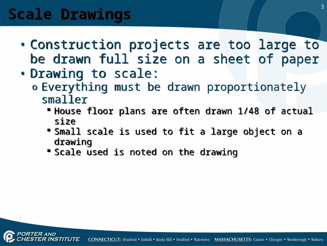
• Construction projects are too large to be drawn full size on a sheet of paper
• Drawing to scale:o Everything must be drawn proportionately smaller
House floor plans are often drawn 1/48 of actual size Small scale is used to fit a large object on a drawing Scale used is noted on the drawing
• Construction projects are too large to be drawn full size on a sheet of paper
• Drawing to scale:o Everything must be drawn proportionately smaller
House floor plans are often drawn 1/48 of actual size Small scale is used to fit a large object on a drawing Scale used is noted on the drawing
4
Scale Drawings (cont’d.)Scale Drawings (cont’d.)
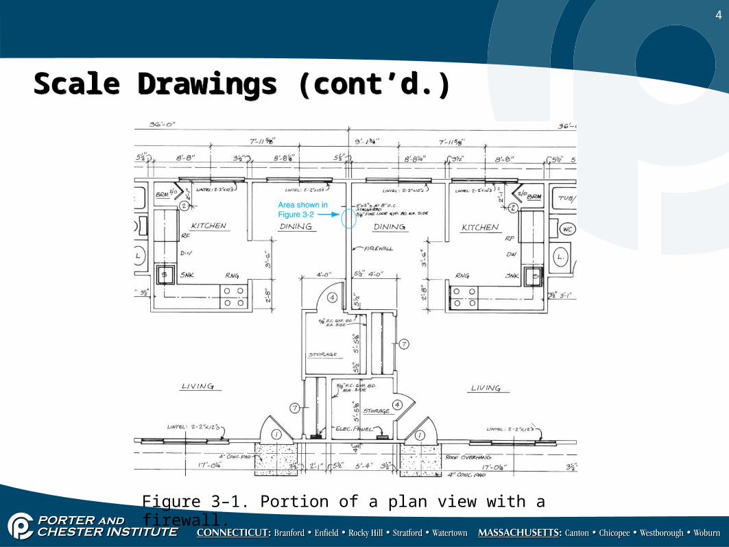
Figure 3–1. Portion of a plan view with a firewall.
5
Scale Drawings (cont’d.)Scale Drawings (cont’d.)
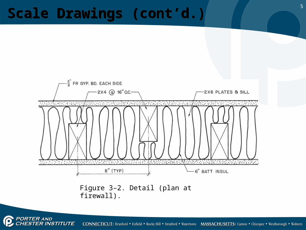
Figure 3–2. Detail (plan at firewall).
6
Reading an Architect’s ScaleReading an Architect’s Scale
• All dimensions should be shown on the drawing• Architect’s scale is used to make drawings to
scaleo Not used to measure the drawing (poor practice)
• All dimensions should be shown on the drawing• Architect’s scale is used to make drawings to
scaleo Not used to measure the drawing (poor practice)
7
Reading an Architect’s Scale (cont’d.)Reading an Architect’s Scale (cont’d.)
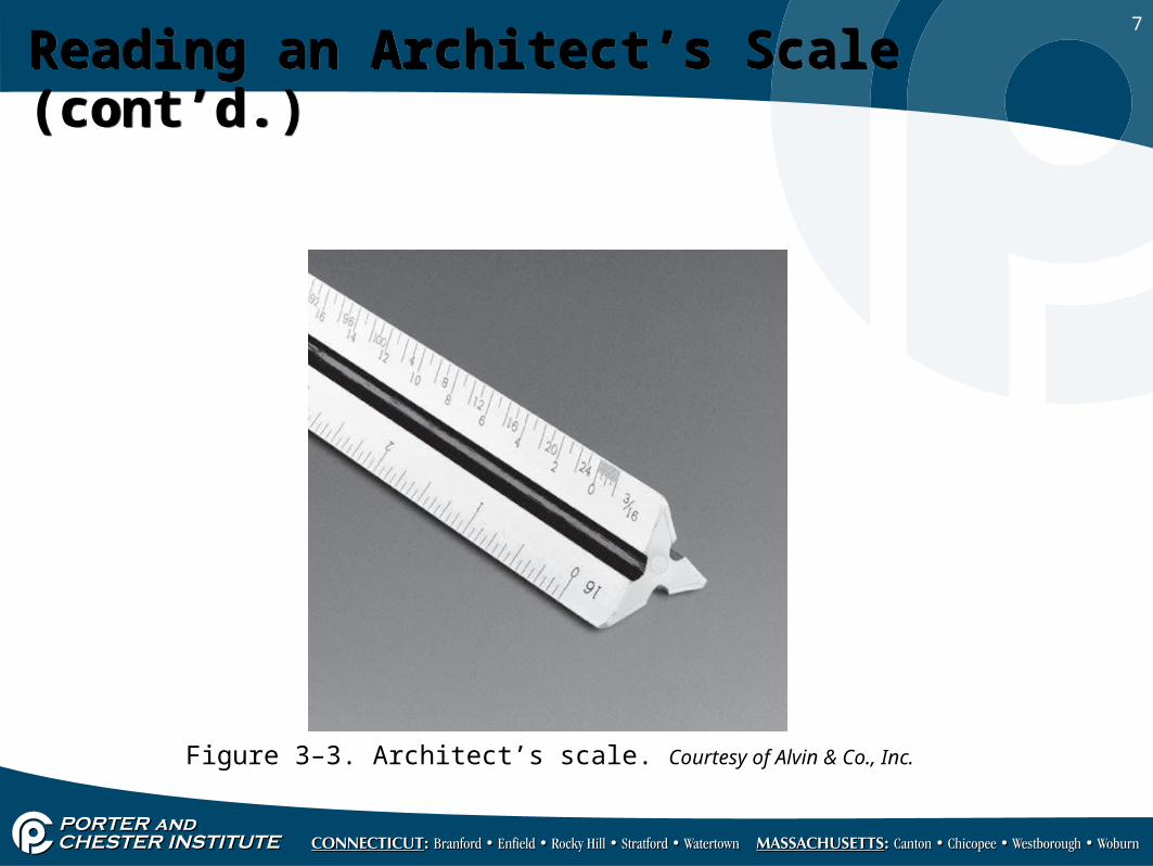
Figure 3–3. Architect’s scale. Courtesy of Alvin & Co., Inc.
8
Reading an Architect’s Scale (cont’d.)Reading an Architect’s Scale (cont’d.)
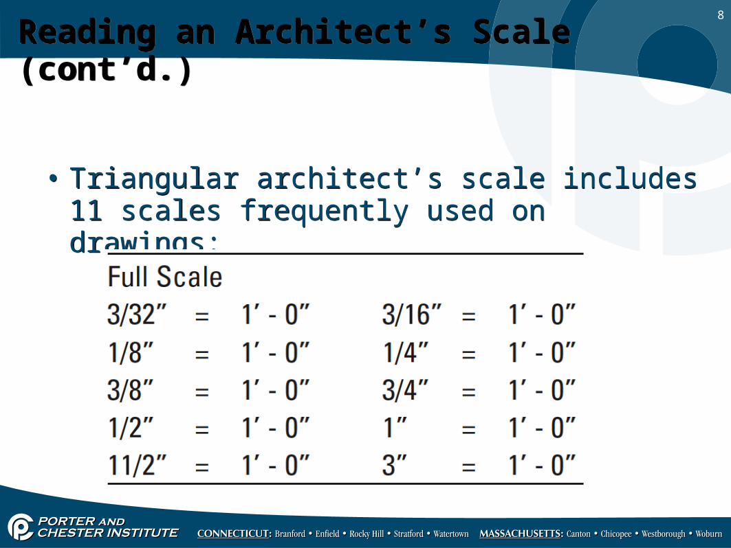
• Triangular architect’s scale includes 11 scales frequently used on drawings:
• Triangular architect’s scale includes 11 scales frequently used on drawings:
9
Reading an Architect’s Scale (cont’d.)Reading an Architect’s Scale (cont’d.)
• Two scales are combined on each faceo Except for full-size scale
Fully divided into sixteenths
• Combined scales work togethero One is twice as large as the othero Zero points and extra divided units are on opposite ends
• Two scales are combined on each faceo Except for full-size scale
Fully divided into sixteenths
• Combined scales work togethero One is twice as large as the othero Zero points and extra divided units are on opposite ends
10
Reading an Architect’s Scale (cont’d.)Reading an Architect’s Scale (cont’d.)
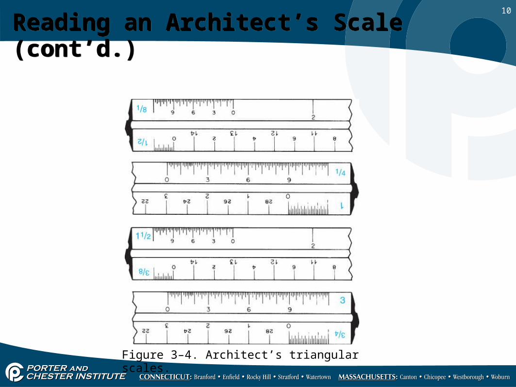
Figure 3–4. Architect’s triangular scales.
11
Reading an Architect’s Scale (cont’d.)Reading an Architect’s Scale (cont’d.)
• Fraction, or number, near zero at each scale end indicates unit length in incheso Used to represent one foot of actual building
• Extra unit near zero end of scale is subdivided into twelfths of a foot (inches) o Fractions of inches on larger scales
• Fraction, or number, near zero at each scale end indicates unit length in incheso Used to represent one foot of actual building
• Extra unit near zero end of scale is subdivided into twelfths of a foot (inches) o Fractions of inches on larger scales
12
Reading an Architect’s Scale (cont’d.)Reading an Architect’s Scale (cont’d.)
• To read the scale:o ¼-inch scale
Scale is divided on left from zero toward ¼ mark Each line represents one inch
Counting marks from zero towards ¼ mark, there are 12 lines marked on the scale
Each line is one inch on the ¼" = 1' - 0" scale
• To read the scale:o ¼-inch scale
Scale is divided on left from zero toward ¼ mark Each line represents one inch
Counting marks from zero towards ¼ mark, there are 12 lines marked on the scale
Each line is one inch on the ¼" = 1' - 0" scale
13
Reading an Architect’s Scale (cont’d.)Reading an Architect’s Scale (cont’d.)
• To read the scale (cont’d.):o 1/8-inch scale
1/8 is on opposite end of the same sideo Read in opposite directiono Counting from zero, there are six lines
Each represents two inches at the 1/8-inch scale
• To read the scale (cont’d.):o 1/8-inch scale
1/8 is on opposite end of the same sideo Read in opposite directiono Counting from zero, there are six lines
Each represents two inches at the 1/8-inch scale
14
Reading an Architect’s Scale (cont’d.)Reading an Architect’s Scale (cont’d.)
• To read the scale (cont’d.):o 1½ -inch scale
Divided unit is broken into twelfths of a foot (inches) and fractional parts of an inch
Figures 3, 6, and 9 represent these inch measurements at the 1½" = 1' - 0" scale
• To read the scale (cont’d.):o 1½ -inch scale
Divided unit is broken into twelfths of a foot (inches) and fractional parts of an inch
Figures 3, 6, and 9 represent these inch measurements at the 1½" = 1' - 0" scale
15
Alphabet of LinesAlphabet of Lines
16
ObjectivesObjectives
• After completing this unit, you will be able to identify and understand the meaning of the listed lines:o Object lineso Dashed lines (hidden and phantom)o Extension lines and dimension lineso Centerlineso Leaderso Cutting-plane lines
• After completing this unit, you will be able to identify and understand the meaning of the listed lines:o Object lineso Dashed lines (hidden and phantom)o Extension lines and dimension lineso Centerlineso Leaderso Cutting-plane lines
17
IntroductionIntroduction
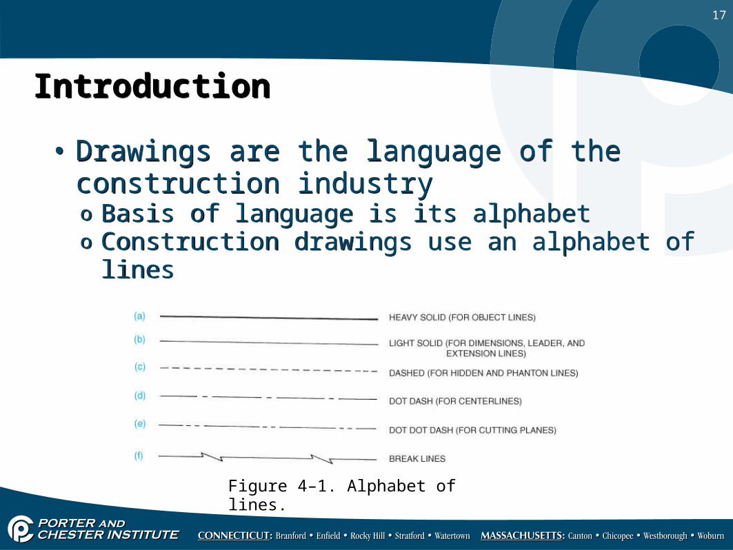
• Drawings are the language of the construction industry o Basis of language is its alphabeto Construction drawings use an alphabet of lines
• Drawings are the language of the construction industry o Basis of language is its alphabeto Construction drawings use an alphabet of lines
Figure 4–1. Alphabet of lines.
18
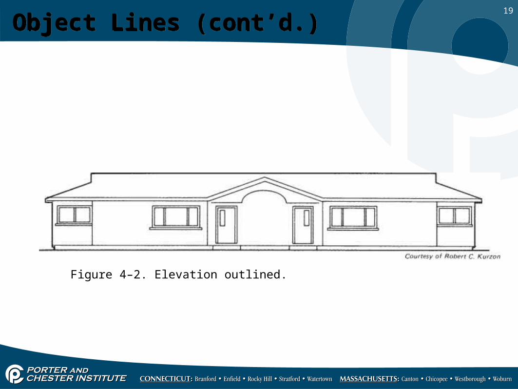
Object LinesObject Lines
• Line weight or thickness is varied to show relative importanceo Help distinguish basic shape from surface details
• Object lines are used to show object shapeo All visible edges are represented by object lines
• Line weight or thickness is varied to show relative importanceo Help distinguish basic shape from surface details
• Object lines are used to show object shapeo All visible edges are represented by object lines
19
Object Lines (cont’d.)Object Lines (cont’d.)
Figure 4–2. Elevation outlined.
20
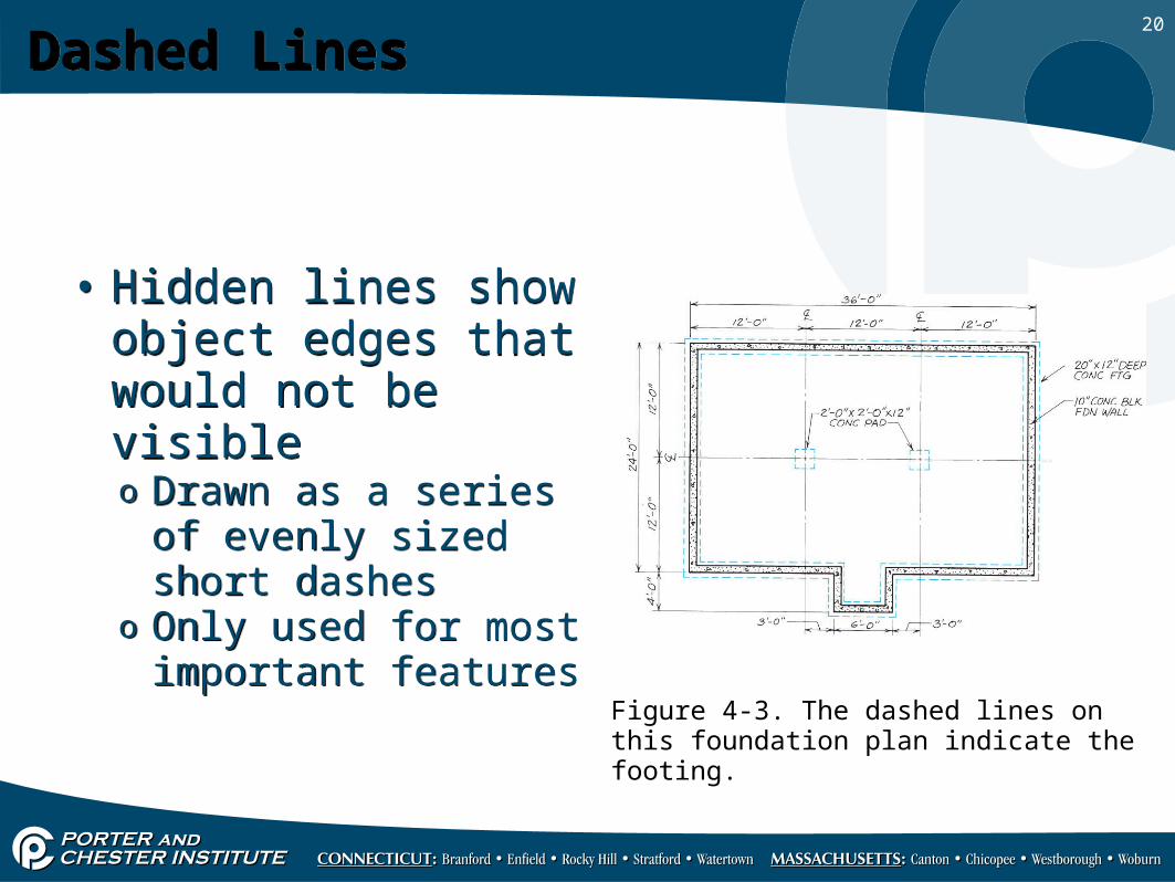
Dashed LinesDashed Lines
• Hidden lines show object edges that would not be visibleo Drawn as a series of
evenly sized short dasheso Only used for most
important features
• Hidden lines show object edges that would not be visibleo Drawn as a series of
evenly sized short dasheso Only used for most
important features
Figure 4-3. The dashed lines on this foundation plan indicate the footing.
21
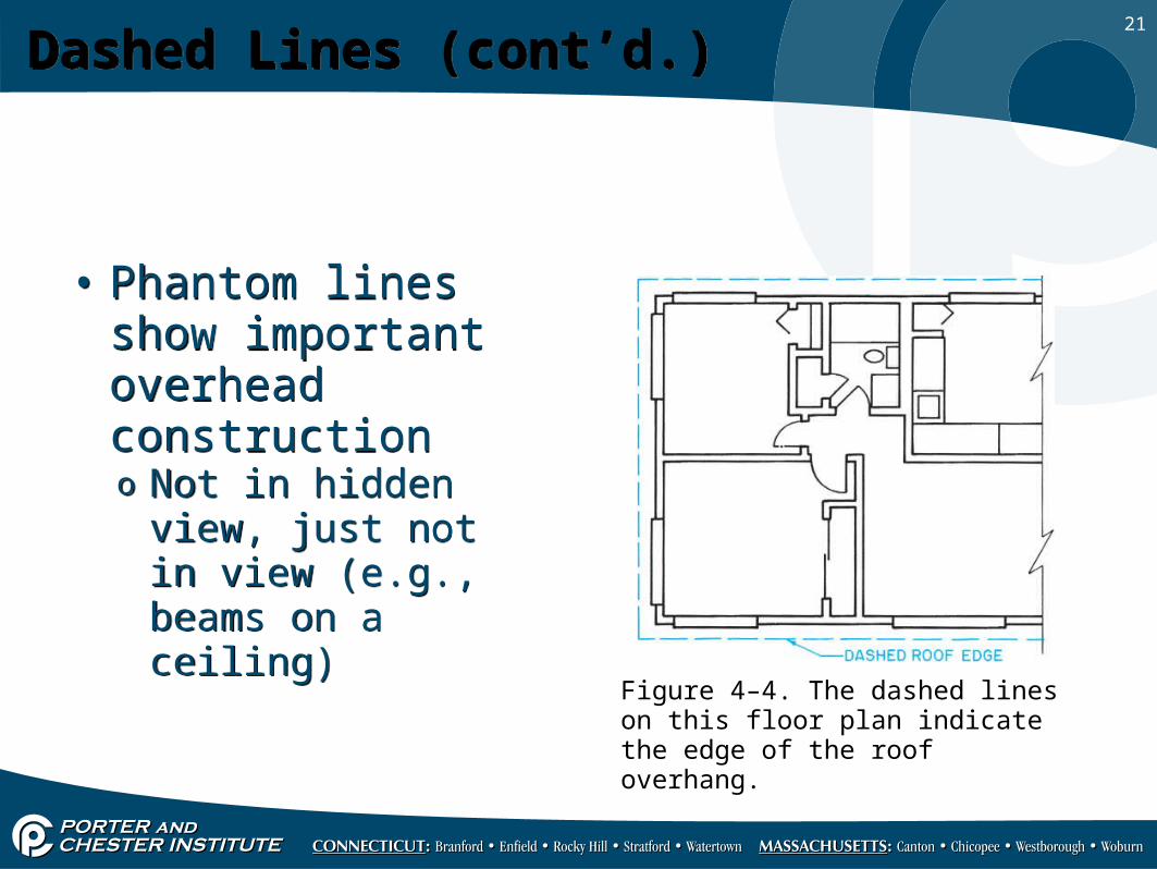
Dashed Lines (cont’d.)Dashed Lines (cont’d.)
• Phantom lines show important overhead constructiono Not in hidden view,
just not in view (e.g., beams on a ceiling)
• Phantom lines show important overhead constructiono Not in hidden view,
just not in view (e.g., beams on a ceiling)
Figure 4–4. The dashed lines on this floor plan indicate the edge of the roof overhang.
22
Dashed Lines (cont’d.)Dashed Lines (cont’d.)
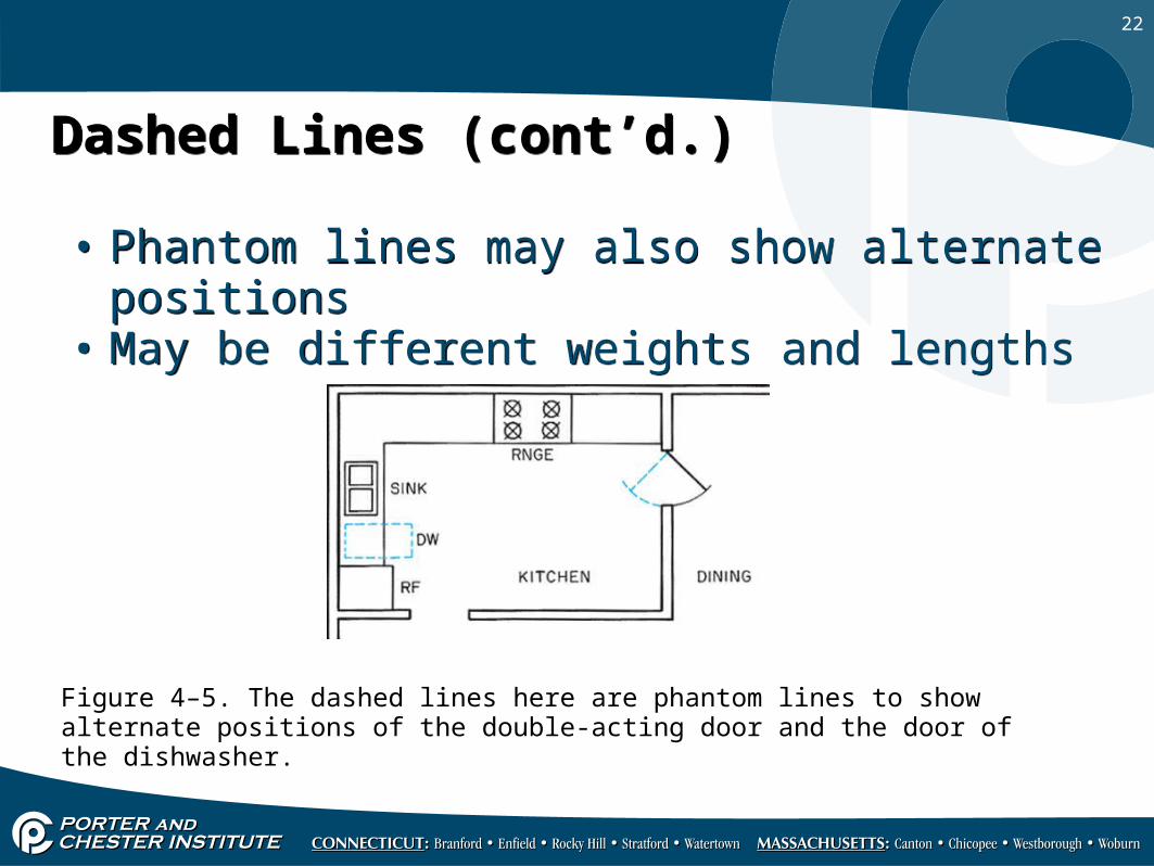
• Phantom lines may also show alternate positions• May be different weights and lengths• Phantom lines may also show alternate positions• May be different weights and lengths
Figure 4–5. The dashed lines here are phantom lines to show alternate positions of the double-acting door and the door of the dishwasher.
23
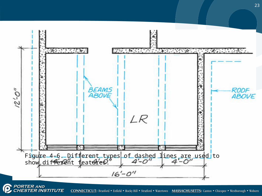
Figure 4–6. Different types of dashed lines are used to show different features.
24
Extension Lines and Dimension LinesExtension Lines and Dimension Lines
• Extension lines:o Thin, solid lines that project from an object to show
extent or limits of a dimension Do not quite touch the object they indicate
• Extension lines:o Thin, solid lines that project from an object to show
extent or limits of a dimension Do not quite touch the object they indicate
25
Extension Lines and Dimension Lines (cont’d.)Extension Lines and Dimension Lines (cont’d.)• Dimension lines:
o Solid lines of the same weight as extension lineso Drawn from one extension line to the nexto Dimension is lettered above the dimension lineo Expressed in feet and incheso Chain dimensions are dimensions added together to
come up with one overall dimension
• Dimension lines:o Solid lines of the same weight as extension lineso Drawn from one extension line to the nexto Dimension is lettered above the dimension lineo Expressed in feet and incheso Chain dimensions are dimensions added together to
come up with one overall dimension
26
Extension Lines and Dimension Lines (cont’d.)Extension Lines and Dimension Lines (cont’d.)
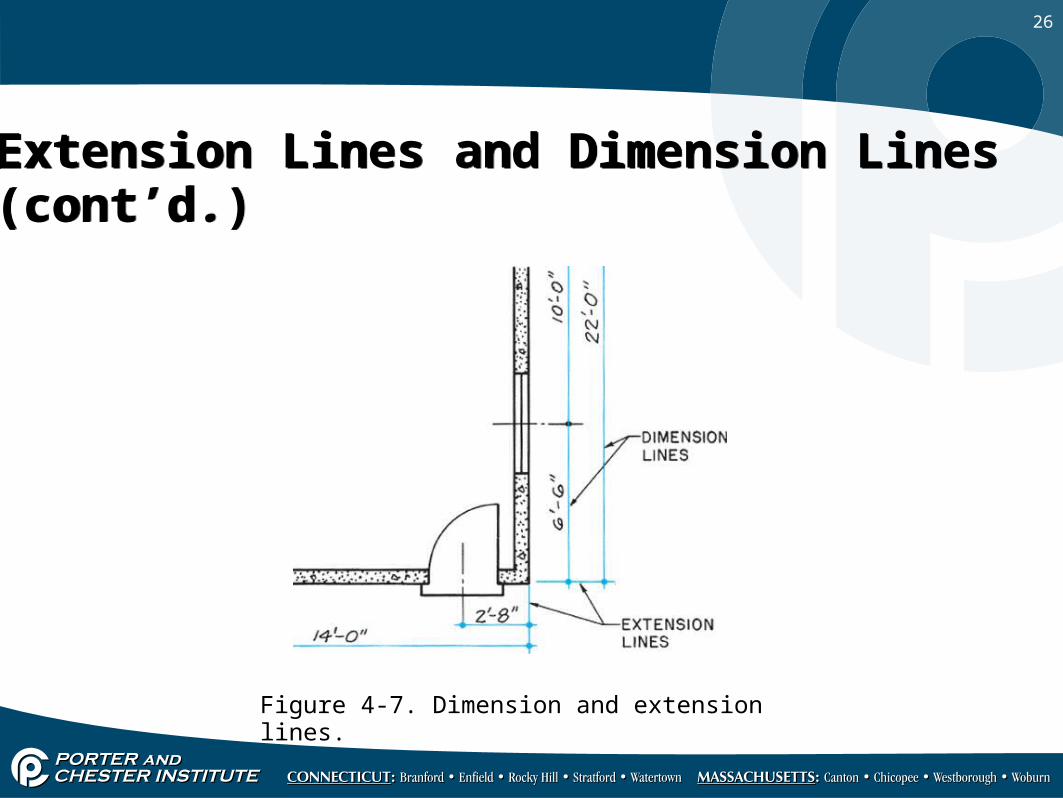
Figure 4-7. Dimension and extension lines.
27
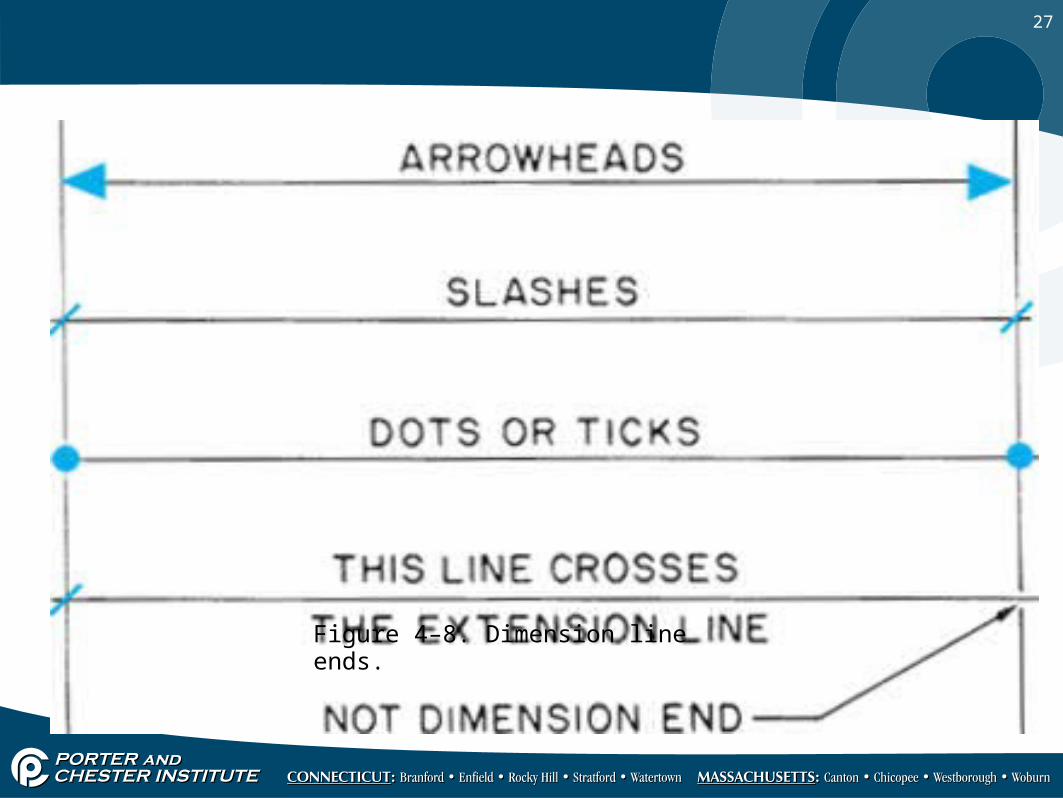
Figure 4–8. Dimension line ends.
28
CenterlinesCenterlines
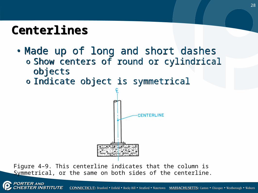
• Made up of long and short dasheso Show centers of round or cylindrical objectso Indicate object is symmetrical
• Made up of long and short dasheso Show centers of round or cylindrical objectso Indicate object is symmetrical
Figure 4–9. This centerline indicates that the column isSymmetrical, or the same on both sides of the centerline.
29
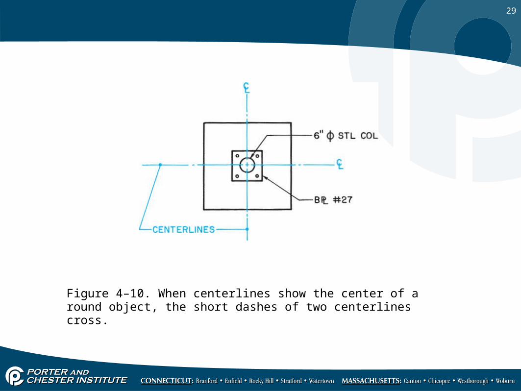
Figure 4–10. When centerlines show the center of a round object, the short dashes of two centerlines cross.
30
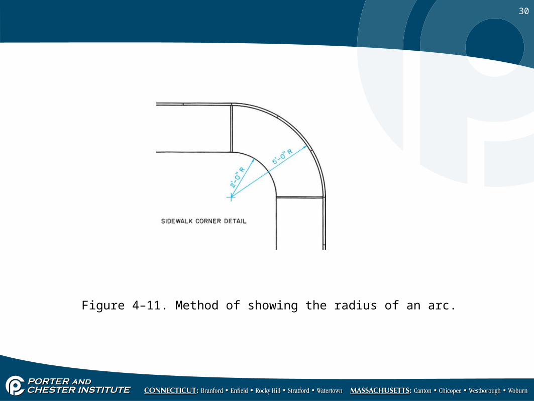
Figure 4–11. Method of showing the radius of an arc.
31
LeadersLeaders
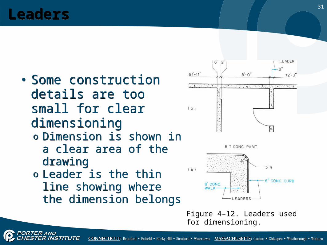
• Some construction details are too small for clear dimensioningo Dimension is shown in a
clear area of the drawingo Leader is the thin line
showing where the dimension belongs
• Some construction details are too small for clear dimensioningo Dimension is shown in a
clear area of the drawingo Leader is the thin line
showing where the dimension belongs
Figure 4–12. Leaders used for dimensioning.
32
Cutting-Plane LinesCutting-Plane Lines
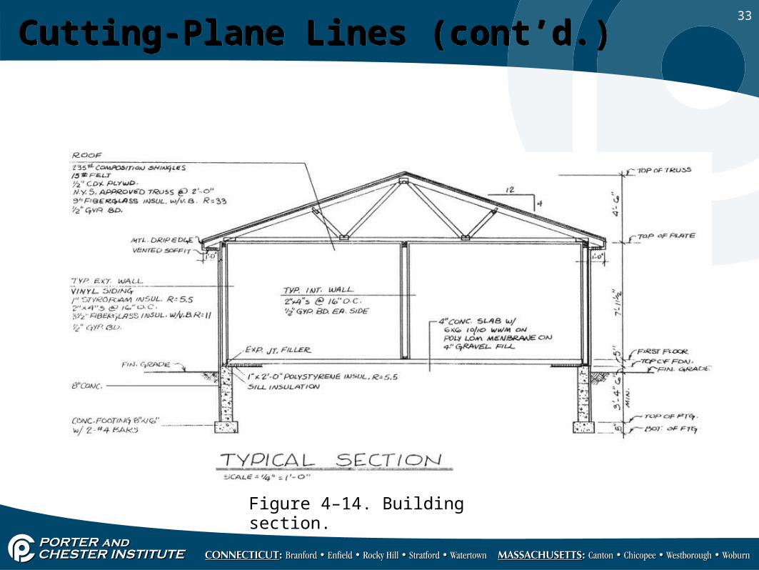
• Show where imaginary cut was made in section viewo Usually a heavy line with long dashes and pairs of short
dasheso Typical sections are not shown
They would be the same if drawn from an imaginary cut in most parts of the building
• Show where imaginary cut was made in section viewo Usually a heavy line with long dashes and pairs of short
dasheso Typical sections are not shown
They would be the same if drawn from an imaginary cut in most parts of the building
33
Cutting-Plane Lines (cont’d.)Cutting-Plane Lines (cont’d.)
Figure 4–14. Building section.