Embed Size (px)
Citation preview
1
Francis Agha Nnachi NAFCO Engineering Training [email protected]
GCC PLANT
FACTORIES
THEORY PAST
QUESTIONS AND
ANSWER
November 1989 – June 2017
Compiled by
Dr Francis Nnachi
Pr Eng, Cert Eng (GCC),
D Tech, M Sc., M Tech., B Eng. Electrical Engineering
SM.SAIEE; M.ICMEESA
Distributed free of charge If you wish to attend our every Saturday GCC preparatory class in Witbank,
call 0762391548.
You can also join our wattsup group to be able to have access to relevant
information
It’s time to pass!
It’s your time to pass!!

2
Francis Agha Nnachi NAFCO Engineering Training [email protected]
Preface
This document has been developed for candidates preparing for their GCC factory plant
examination. It covers all past theory GCC Factory examination questions from 1989 to 2016. I’ve
tried to answer most of the questions using the listed reference books and other technical documents.
If you happens to know an answer to any unanswered questions, feel free to e-mail the question, the
year and the answer and I will send to you updated version of this document.
e-mail: [email protected]
Reference documents
Principles of power system by VK. Mehta and Rohit Mehta
SANS 10142-1 & 2 Wiring code
SANS 10198-1:2004: The selection, handling and installation of electric power cables of rating not
exceeding 33 kV Part 1: Definitions and statutory requirements
SANS10108 - The classification of hazardous locations and the selection of apparatus to use in such
locations
SANS 10198-2:2004: The selection, handling and installation of electric power cables of rating not
exceeding 33 kV Part 2: Selection of cable type and methods of installation
SANS 10292:2001: Earthing of low-voltage (LV) distribution systems
SANS 1507
OHSMS 18001- Occupational health and safety management system- specifications
OHSAS 18002- Guidelines for the implementation of OHSAS 18001
ISO 14001 (environment)
ISO 9001 (quality)
Acknowledgement
I would like to acknowledge DOL & DOE for the use of the questions from GCC plant question
papers to make up this document.

3
Francis Agha Nnachi NAFCO Engineering Training [email protected]
TABLE OF CONTENTS
June 2017 ........................................................................................................................................................................ 5
November 2016 ............................................................................................................................................................ 12
June 2016 ...................................................................................................................................................................... 13
November 2015 ............................................................................................................................................................ 20
JUNE 2015.................................................................................................................................................................... 23
NOVEMBER 2014 ....................................................................................................................................................... 28
JUNE 2014.................................................................................................................................................................... 34
NOVEMBER 2013 ....................................................................................................................................................... 38
JUNE 2013.................................................................................................................................................................... 41
NOVEMBER 2012 ....................................................................................................................................................... 45
JUNE 2012.................................................................................................................................................................... 49
NOVEMBER 2011 ....................................................................................................................................................... 59
June 2011 ...................................................................................................................................................................... 66
November 2010 ............................................................................................................................................................ 76
JUNE 2010.................................................................................................................................................................... 85
November 2009 .......................................................................................................................................................... 100
June 2009 .................................................................................................................................................................... 108
November 2008 .......................................................................................................................................................... 121
June 2008 .................................................................................................................................................................... 123
November 2007 .......................................................................................................................................................... 133
June 2007 .................................................................................................................................................................... 142
November 2006 .......................................................................................................................................................... 147
June 2006 .................................................................................................................................................................... 157
November 2005 .......................................................................................................................................................... 164
June 2005 .................................................................................................................................................................... 175
November 2004 .......................................................................................................................................................... 183
June 2004 .................................................................................................................................................................... 190
November 2003 .......................................................................................................................................................... 197
June 2003 .................................................................................................................................................................... 199

4
Francis Agha Nnachi NAFCO Engineering Training [email protected]
November 2002 .......................................................................................................................................................... 203
JUNE 2002.................................................................................................................................................................. 207
NOVEMBER 2001 ..................................................................................................................................................... 211
November 1993 .......................................................................................................................................................... 214
June 1993 .................................................................................................................................................................... 221
November 1992 .......................................................................................................................................................... 226
June 1992 .................................................................................................................................................................... 233
November 1991 .......................................................................................................................................................... 237
June 1991 .................................................................................................................................................................... 246
November 1990 .......................................................................................................................................................... 249
JUNE 1990.................................................................................................................................................................. 252
NOVEMBER 1989 ..................................................................................................................................................... 255
Appendix ..................................................................................................................................................................... 257

5
Francis Agha Nnachi NAFCO Engineering Training [email protected]
------------------------------------------------------------------------------------------------------------------------------
June 2017
-----------------------------------------------------------------------------------------------------------------------------------------
QUESTION 1.1 (repeat of Nov 2011 Q 1.1)
Give the functions of the dual Mobrey level control fitted to a coal fired steam generator. (4)
Answer:
Float operated two switch device that performs the following functions
1. Switches feed pump on and off to maintain water level in the boiler by varying the opening of a modulating
feed valve
2. Switches on an alarm and a red light on the panel if water level in the boiler drops below normal
3. Switches the steam generator off if water level steam generator drops below the low-low alarm.
Question 1.2 (repeat of June 2011 Q1.2)
Describe how to blow down the mobrey controls (4)
Answer:
Blow down mobrey controls
1. Normal working position
a. The valve handle is kept in the fully turned-out position
b. The steam pipe and float chamber are connected with the water pipe
2. Blowdown of water pipe
a. Turn the valve handle inwards about 2 ½ turns (clockwise). Wait 5 seconds
b. The steam pipe and float chamber are closed off
c. The water pipe is blowing through to the drain
3. Blowdown of steam pipe and float chamber
a. Turn the valve handle inwards fully (about 5 turns clockwise) wait 5 seconds)
b. The steam pipe and float chamber are blowing through to the drain. The water pipe is closed off
c. Turn the valve fully outwards (anticlockwise) and close firmly. Check for leakage by feeling
temperature of drainpipe after 15 minutes
Question 1.3
Name four other accessories that must be installed on an evaporator for a steam generator. (4)
Answer:
• Pressure gauge
• Fuse plugs and temperature gauge
• Water level sight glass
• Safety relieve valve

6
Francis Agha Nnachi NAFCO Engineering Training [email protected]
Question 2.1
Oil circuit breaker are not manufactured on a large scale anymore by the world’s leading switchgear manufacturer’s.
This is mainly due to the major disadvantages out weighing the advantages.
Name three advantages and three disadvantages oil circuit breakers (6)
Answer
Advantages
1. It absorbs the arc energy to decompose the oil into gases which have excellent cooling properties
2. The oil acts as an insulator and permits smaller clearance between live conductors and earthed components
3. The surrounding oil presents cooling surface in close proximity to the arc
Disadvantages
1. The oil is inflammable and there is a risk of fire
2. The oil may form an explosive mixture with air
3. The arcing products (e.g. carbon) remain in the oil and its quality deteriorates with successive operations.
4. It requires additional maintenance to ensure that the oil is kept in a suitable and adequate operational state
(Source: Principles of power system by VK. Mehta and Rohit Mehta, page 464 -465)
Question 3.1 (Nov. 2006 Q 3.1; Nov. 2010 Q 3.1, June 2012 Q 3.1, June 2014 Q 3.1, June 2015 Q3.1)
An organization establishes and maintains an occupational Health and Safety Management System. The employer
authorized an occupational health and Safety (OHS) policy that clearly states overall health and safety objectives as
well as a commitment to improving health and safety performance
Name 6 requirements of this policy
Answer
OH&S Policy requirement
Ensure that the policy
a) is appropriate to the nature and scale of the organization’s OH&S risks;
b) includes a commitment to prevention of injury and ill health and continual improvement in OH&S management
and OH&S performance;
c) includes a commitment to at least comply with applicable legal requirements and with other requirements to which
the organization subscribes that relate to its OH&S hazards;
d) provides the framework for setting and reviewing OH&S objectives;
e) is documented, implemented and maintained;
f) is communicated to all persons working under the control of the organization with the intent that they are made
aware of their individual OH&S obligations;
g) is available to interested parties
h) is reviewed periodically ensuring that it remains relevant and appropriate to the organisation

7
Francis Agha Nnachi NAFCO Engineering Training [email protected]
Question 3.2
A project manager has been appointed as a part of a project team for the installation of the refrigeration plant.
Name FOUR core elements and four supporting elements of project management (8)
Answer
Core elements
1. Resources
2. Time
3. Money
4. Scope
Supporting elements
1. Risk management
2. Quality management
3. Communication management
4. Procurement management
Question 3.3
The causes of electrical faults can either be due to human or natural causes. Name 3 of each type of fault (6)
Answer 3.3
Human error
- Design problem
- Improper installation
- Public damage of electrical cables
- Workmen digging trenches unintentionally into an underground cable
- etc
Natural cause
- Ageing of insulation or insulation failure or material deterioration
- Wear and tear
- Lightning caused faults
- Tree caused faults: Trees can cause faults in several ways: growth into conductors, failing trees or branches
bridging gaps or pushing conductors together, and failing trees or branches causing mechanical damage
- Animal caused faults: There are many types of animals could cause fault in power system, including tree
squirrel, birds, snake and so on
- Veld fire
- Rain, ice, storm, earthquakes
- Harsh atmospheric condition

8
Francis Agha Nnachi NAFCO Engineering Training [email protected]
Question 4.1 (repeated: Nov 2014 Q 4.2; Q 7.4 June 2012; Q 5.2 Nov. 2010; Q7.2 Nov. 2007)
Name 10 visual inspections to be carried out as well as 10 tests with meaningful readings/results to ensure a valid
certificate of competence according to the SANS 10142-1 Wiring code for an electrical installations (10)
Answer 4.1
Visual inspections
During the inspection, confirm that
1) accessible components are correctly selected
2) all protective devices are of the correct rating,
3) all protective devices are capable of withstanding the prospective short-circuit current
4) Conductors are of the correct rating and current-carrying capacity for the protective devices and connected
load (Pay attention to voltage rating, voltage drop, current-carrying capacity and short-circuit
capacity.)
5) components have been correctly installed, and are accessible where necessary
6) disconnecting devices (isolators) are correctly located and that all switchgear switches the phase conductors,
7) Different circuits are separated electrically. Circuits for control communication, security, detection, safety
and the like, should be electrically separated and, where specified, physically separated,
8) connections of conductors and earthing and bonding are mechanically sound,
9) connections of conductors and earthing and bonding are electrically continuous,
10) Circuits, fuses, switching devices, terminals, earth leakage units, circuit-breakers and distribution boards are
correctly and permanently identified, marked or labelled, [Pay attention to installations where circuit-
breakers are used in series-connected (cascaded) systems].
11) the integrity of the fire barrier has been maintained where an electrical system passes through a fire barrier,
12) safety lighting, emergency lighting and safety signs function correctly,
13) The installation including all accessible compoenets should comply with SANS 10142-1
14) the installation complies with the general safety principles of this edition of this part of SANS 10142 and is
reasonably safe
15) where an alternative supply is installed, it complies with all the requirements in 7.12, and
16) the position of the readily accessible earthing terminal for the earth connection of other services made by
installers of such services
Tests
1. Continuity of bonding: ≤ 0.2Ω
2. Resistance of earth continuity conductor: < 1.7 Ω for protective device 6.3 A; < 0.55 for protective
device 20 A
3. Continuity of ring circuits (if applicable): buzzer will sound if there is continuity
4. Earth loop impedance test:): max earth fault loop impedance 𝑍=𝑉/(2×𝐼) Where I = size of main circuit
breaker Z = 𝑣
2.𝐼 =
240
2.60 = 2Ω ; Z ≤ 2Ω
5. Prospective short-circuit current indicative: 0.1 ≤ 10 kA
6. Elevated voltage between incoming neutral and external earth (ground): ≤ 25 V; if > 25 V notify the
supply; > 50 V, disconnect the supply and notify the supply authority
7. Earth resistance at electrode (if required): R = 𝑣
2.1 =
240
2.60 = 2Ω :: R ≤ 2Ω
8. Insulation resistance: ≥ 1 MΩ
9. Voltage at main distribution board with no load for each phase to neutral: Within limit of ±10% on 230
single phase, 230/400 3-phase 4-wire or ±5% for 525 V declared voltage

9
Francis Agha Nnachi NAFCO Engineering Training [email protected]
10. Voltage at main distribution board with load (as calculated for full load) for each phase to neutral:
Within limit of ±10% on 230 single phase, 230/400 3-phase 4-wire or ±5% for 525 V declared voltage
11. Voltage at available load (worst condition as calculated for full load) for each phase to eutral: Voltage
drop from point of supply to point of consumption shall not exceed 5 %.
12. Operation of all earth leakage units: ≤ 30 mA
13. Operation of all earth leakage test buttons- correct: yes/no
14. Polarity of points of consumption- correct: yes/no
15. Phase rotation at point of consumption for three- phase systems- correct: yes/no
16. All switching devises make-and break circuits-correct: yes/no
Source (SANS10142-1)
Question 4.2
You have implemented a predictive maintenance program at the factory. The following equipment are
listed as critical equipment: -
4.2.1 Transformers
4.2.2 Distribution boards
4.2.3 Motors
4.2.4 Control systems
4.2.5 Lighting panels
Handheld test tool are used to check for normal conditions.
What are the key indicators to look for and what type of instrument will you use to detect these
indicators (10)
ANSWER 4.2
Key indicators Instrument
Hot spots, slack/loose connectors, Corroded
connections
Infrared thermometer
Temperature / heat Infrared thermometer, digital temperature meter
Motor failures like brush contact-wear and
armature shorts
Infrared thermometer
broken or undersized wires or defective insulation Infrared thermometer
Speed measurement Tachometer
Noise Digital sound meter
Illumination levels / light output Lux meter
Current Amp meter, clamp on meter
Voltage Volt meter, multi meter
10
Francis Agha Nnachi NAFCO Engineering Training [email protected]
Power Power meter, power analyser
Question 7.1 (repeated Nov. 2006 Q4.1, June 2010, June 2011 Q6.2)
Name four items to check on a steel wire rope used on a gantry crane when carrying out a periodic inspection and
discus each item. (8)
Answer
1. Broken wires (nature & number of broken wires): A wire rope must be discarded if the permissible number
of wire breaks is reached or exceeded. It must also be replaced when local concentrations of wire breaks
occur.
2. Reduction in diameter: reduction in diameter can be caused by abrasion, corrosion or a local failure of the
rope core.
3. Decreased elasticity
4. Corrosion: corrosion may be external or internal, general or localized. A wire should be discarded when the
surface of the wires is severely roughened or pitted, or if the wires are slack within the strands due to
wastage.
5. Rope deformation: (a) Waviness: this deformation, while it may not necessarily affect the strength of the
rope, can transmit pulsation and produce uneven rope wear.( b). Birdcage (basket deformation): A birdcage
develops when the outer layer of strands becomes longer than the inner layer or layers. The condition may
occur as a result of incorrect fitting, tight sheaves, shock loading, incorrect use of a swivel or the application
of a heavy load to a new rope before the strands have settled into position. Ropes with a birdcage should be
discarded. (c). Loop Formation: wires or groups of wires may form a line of loops parallel to the axis of the
rope. This deformation is often caused by shock-loading. Loop formations are justification for discard.(d)
Nodes, (e) thining of the ropes, (f) misplaced outer wires, (g) kinks, (h) flat areas
6. Damage caused by heat
7. Rope strength
8. Abuse
9. Abrasive wear

11
Francis Agha Nnachi NAFCO Engineering Training [email protected]
Question 8.1 (Repeat of Nov 2013 Q 7.3)
Name 5 types of areas that shall be classified as hazardous locations (5)
Answer
• Spray painting booths
• Service station - Petrol pumps, diesel and gas stations
Flour mills
• Battery charging locations
• Coal storage facilities – cola mines
• Grain silos
• Medical locations
• Air craft hangers
• Petrochemical factories
Answer
SANS10142-1: 7.14 (page 265) Hazardous locations
1. Petrol pumps
2. Spray painting booths
3. Areas for the storage, mixing and use of flammable fuels, paints or solvents
4. Grain silos and flour mills
5. Coal storage facilities
6. Wine cellars
7. Areas for the storage and filling of LPG cylinders
8. Battery charging locations
9. Sewage plant
Question 8.2
Name 5 explosion protection techniques used in explosive gas atmosphere (5)
Answer
• Flameproof (Ex d)
• Specially protected (Ex s)
• Increased safety (Ex e)
• Encapsulated (Ex m)
• Power-filled or sand-filled (Ex q)
• Intrinsically safe (Ex “ia” or Ex “ib”)
• Pressurized (Ex p) apparatus that has interlock that isolate it automatically when the fresh air supply or inert
gas supply fails
• Non-sparking (Ex n)
• Pressurized (Ex p) apparatus that has visual or adubile warning system to indicate failure of the fresh air
supply or inert-gas supply
• Oil immersion o

12
Francis Agha Nnachi NAFCO Engineering Training [email protected]
------------------------------------------------------------------------------------------------------------------------------
November 2016
-----------------------------------------------------------------------------------------------------------------------------------------
Question 1.1
Give three purposes of water treatment in a steam generator
Answer
Question 1.2
Name one advantage and one disadvantage of using steam for sootblower in a steam generator
Answer
Question 2.2
There are several steps, from manufacturing till when it is used, where there is a need to verify the integrity of a
power transformer. Name five such stages
Answer
Question 2.3
Name three main reasons why oil is used in power transformers
Answer
- For insulation
- For cooling
-
13
Francis Agha Nnachi NAFCO Engineering Training [email protected]
------------------------------------------------------------------------------------------------------------------------------
June 2016
-----------------------------------------------------------------------------------------------------------------------------------------
Question 1.1
You have installed a new 10 ton fire-tube steam generator at the plant that must be inspected and tested by an in-
service approved inspection authority before the commissioning of the steam generator.
Name TEN items that must be inspected by the approved inspection authority. (10 marks)
Answer
• High and low water alarms and cut off
• Check water gauges glass cocks
• Is the blowdown in safe area?
• Is safety valve blowing off into safe area?
• Is safety valve set to blow off correctly?
• Is safety valve sized correctly?
• Check setting of pressure regulation devices
• Check fire / burner safety devices
• Check grate controls
• Check compliance of appurtenances to regulations and standards
• Check for correct signage
• Check for lighting inside the steam generator
• Check for ventilation inside the steam generator
• Check clearance around the generator
• Confirm if the generator attendants are competent
Question 1.2 .1 (Repeat of Nov. 2008 Question 3.2)
You intend to implement a risk-based inspection management system
1.2.1 What is the reason why users will implement such system? (2 marks)
Answer
The purposes of RBI include:
1. To move away from time based inspection often governed by minimum compliance with rules, regulations
and standards for inspection.

14
Francis Agha Nnachi NAFCO Engineering Training [email protected]
2. To apply a strategy of doing what is needed for safeguarding integrity and improving reliability and
availability of the asset by planning and executing those inspections that are needed.
3. To provide economic benefits such as fewer inspections, fewer or shorter shutdowns and longer run length.
4. To safeguard integrity.
5. To reduce the risk of failure.
Question 1.2 .2
You intend to implement a risk-based inspection management system
1.2.2 Which documents will you request from the person who will verify the system to ensure that he or she is
allowed to do it? (2 marks)
Answer
• Accreditation certificate from SANAS
• Approved certificate from DoL
Question 2.2 (Repeat of June 2011 Q 2.2, June 2007 Q 2.2)
Name FOUR types of applications for a direct-current series motor and TWO reasons why it is more suitable than
other types of motors (6 marks)
Answer
1. Cranes and hoists – where large heavy loads will be raised and lowered. The series motor provides the
starting torque required for moving large loads
2. Electric trains: series motors that provide the required torque and horsepower to get massive amounts of
weight moving
3. Elevators
4. Steelcars
5. Conveyors
6. Rapid transit system
TWO reasons why it is more suitable than other types of motors
• Large starting torque and
• Speeds from zero upwards are easily obtainable
Question 2.3
Name FOUR requirements of an overcurrent protective device for an alternating-current electrical motor (4 marks)
Answer
• Have a tripping device value that is a near to the full load rated current of the motor as practicable

15
Francis Agha Nnachi NAFCO Engineering Training [email protected]
• Have sufficient time delay to allow the motor to start and accelerate uncer normal conditions
• Prevent a multiphase motor from continuing to operate under load if single phasing occurs
• In the case of an automatically controlled motor, have to be manually reset after operation before allowing
restarting of the motor
(Source SANS 10142-1__6.16.5.1.3)
0 Question 3.1 (Repeat of June 2013 Q 3.1)
A large mechanical workshop is part of your responsibility as an engineer. List TEN general points which are
important with regards to safety in the workshop (5 marks)
Answer
• Visible notices and signs as required by regulations and standards
• All tools are properly maintained
• Adequate tools are provided for the right jobs to be performed
• all faulty equipment to be marked as unfit to be used
• equipment not in use must be stored in dedicated area
• equipment shall only be used for the purpose it is intended to be used
• Workplace free from hazards
• Floors free from tripping and slipping
• Machinery operated and maintained to manufacturer’s instructions
• All controls and emergency devices are working correctly
• Sufficient ventilation
• Health and safety meetings are held
• Fitness of all workers to perform work
• Supply of PPE are worn by workers
• Adequate guarding & ensure that dangerous places are protected
• Good house keeping
• Safe work procedure
• Employees should not wear something that can be caught in moving machinery e.g. loose clothes, chains,
watches, loose long hair, etc.
• Walkways should be clearly marked
• Provision of correct firefighting equipment
Question 3.2
Inputs to the risk-assessment processes can include information or data on the following:

16
Francis Agha Nnachi NAFCO Engineering Training [email protected]
• Details of location(s) where the work is carried out
• The proximity and scope for hazardous interaction between activities in the workplace
• Security arrangements
Name FIVE other inputs to this process (5 marks)
Answer
• Manufacturers or suppliers instructions to operate and maintains equipment and facilities
• Availability and use of control measures
• Environment conditions affecting the workplace
• Access and escape plans, equipment, signage communication etc.
• Recording data of incidents of work activities
• Details of any work instructions, systems of work and/ or permit to work procedures, prepared for hazardous
tasks
• The findings of any existing assessments relating to hazardous work activity,
• The accuracy and reliability of the data available for the risk assessment
• The human capabilities, behavior, competence, training and experience of those who normally and/ or
occasionally carry out hazardous tasks,
• etc
Question 3.3 (repeat of June 2013 Q 3.4)
Give THREE reasons why the plant engineer must be involved with the managing of the risk in the working
environment (3 marks)
Answer:
• To assist in identifying the risks
• Assist with the evaluation of the risks
• Assist with control measures to mitigate the risks
• Assist with financial recommendations
Question 3.4
The organisation must establish, implement and maintain a procedure for dealing with actual and potential non-
conformities and for taking corrective and preventive action.
Name TWO requirements for procedure to deal with non-conformities (2 marks)
Answer

17
Francis Agha Nnachi NAFCO Engineering Training [email protected]
• Identify: Identifying and correcting nonconformities and taking actions to mitigate their OH&S
consequences
• Investigate: Investigating nonconformities, determining their causes and taking actions in order to avoid
their recurrence
• Evaluate: Evaluating the need for action(s) to prevent nonconformities and implementing appropriate action
designed to avoid their recurrence
• Record: Recoding and communicating the results of corrective actions and preventive actions taken; and
• Review: Reviewing the effectiveness of corrective actions taken
Question 3.5 (June 2013 Q 3.5)
There are two groups of root causes for incidents in the workplace. They are classified as personal and job related.
Name FIVE causes of each group (5 marks)
Answer:
1 - Personal Factors:
a) Lack of knowledge / skill (Training)
b) Improper motivation
c) Physical / Mental problems
d) Inadequate capability
e) Stress
2 – Job Related:
a) Inadequate engineering control
b) Inadequate purchasing of correct tools or equipment
c) Inadequate tools / Equipment – wrong equipment or tool
d) Wear and Tear – worn out equipment or tool
e) Inadequate maintenance
f) Improper instruction / Inadequate work standards
g) Abuse or misuse of tools and equipment
Question 4.1
Each distributor board in an electrical installation is controlled by a switch-disconnector. Name FIVE general
requirements for the switch-disconnector (5 marks)

18
Francis Agha Nnachi NAFCO Engineering Training [email protected]
Answer
The switch-disconnector shall
1. be mounted in the DB board or adjacent to the DB board in the same room
2. in the case of the main or first DB board of an installation, be labelled as "main switch",
3. in the case of a sub-DB, be labelled as "sub-main switch" or “main switch” if the board is labelled “sub-
board …”,
4. Have a danger notice on or near it. The danger notice shall give instructions that the switch-disconnector be
switched off in the event of inadvertent contact or leakage.
5. In the case where an alternative supply is installed, be labelled as required in 7.12.2.1 of SANS10142
(Source SANS 10142-1)
Question 4.2
What considerations apply before the type of wiring and methods of installation in an electrical installation are
determined (5 marks)
Answer
The type of wiring and methods of installation shall be determined after
consideration of the following:
• the location (also consider intentional or inadvertent damage);
• the nature of the building elements for supporting the wiring;
• the accessibility of the wiring to persons and livestock;
• the voltage;
• the electromechanical stresses and thermal effects likely to occur as a
result of short-circuits; and
• stresses imposed on the wiring during installation and in service.
(Source SANS10142-1)

19
Francis Agha Nnachi NAFCO Engineering Training [email protected]
Question 8.2 (Nov. 2010 Q8.2)
Name FIVE advantages of adding a water filter head and filter to a refrigeration system (5 marks)
Answer
Adding Water Filter Capability to an Existing Coolant System.
The addition of water filter head and filter can provide significant benefits to the engine, including:
1. Extended water pump life
2. Maximized cavitation corrosion protection
3. Extended coolant life
4. Improved heat transfer
5. Improved thermostat durability
6. Lower cooling system maintenance costs
Question 8.3
Name THREE possible signs of dirt or contamination in the cooling medium associated with poor to no filteration
(3 marks)
Answer
• Worn rings and scuffed pistons due to poor heat transfer
• Premature water pump failures
• Premature thermostat failures
• Premature radiator failures
Question 8.4
The main function of a lubricant is to reduce friction. Name THREE additional functions of a lubricant ( 3marks)
Answer
• To remove heat
• To avoid accumulation of deposits
• To protect rust and corrosion
• To improve sealing

20
Francis Agha Nnachi NAFCO Engineering Training [email protected]
--------------------------------------------------------------------------------------------------------------------------------
November 2015
------------------------------------------------------------------------------------------------------------------------------------------------
The paper: 62 % theory and 38 % calculations
Question 1.1
Name SIX defects or conditions to check on the waterside of a fire tube steam generator when carrying out a periodic
internal inspection, and discuss how deviations may be corrected. (12 marks)
Answer
Internal Inspection
1. Examine the internal seam and water space. Particular attention for O2 pitting around water line.
2. Examine all internal feed pipes for clear passages, also all connections to alarms, controls, gauge glass ports,
steam and water pipes.
3. Where high and low water alarm floats are fitted, the trays must be clean and all linkages free. They must be
operating within the required limits.
4. Painting of the shell of the boiler must not be done until after the internal inspection has been completed. Renew
fusible plugs, if fitted.
5. Tubes and headers must be examined for wastage around the seating inspection and other holes.
Question 2.2
Name FOUR reasons why induction motors are the preferred choice when selecting motors for hazardous locations.
(4 marks)
Answer
- Cheaper
- More robust
- Slightly higher efficiency
- Better power factor
- Requires less maintenance
- Explosion proof, since the absence of slip-rings and brushes eliminates risk of sparking
Question 2.3
Name and discuss THREE considerations when variable speed drives are used on an induction motor (6 marks)
21
Francis Agha Nnachi NAFCO Engineering Training [email protected]
Answer
Speed Control
A fundamental principal of a Variable Speed Drive is to adjust the speed of an electric motor. The basic command
frequency for Variable Speed Drives is normally from 0 Hz to 50 Hz, but with the average capability to be adjusted
up-to 400 Hz. If the base frequency of a motor is 50 Hz then the final speed will be 8 times the base frequency of the
motor with the command frequency set at 400 Hz.
Practically this is not normal for standard induction motors to operate at these high frequencies due to their design. In
practice a command frequency set point of between 25 Hz and 75 Hz is acceptable without compromising
performance or introducing any mechanical damage to the motor. At low frequency set points, care must be taken
that there is enough cooling produced by the mechanical fan for the motor.
At High frequency set points mechanical failure may occur due to the mechanical design of the motor bearings
normally rated at the design speeds of 2, 4, or 6 poles. At high frequency command speeds, care should be taken as
torque loss may be experienced.
Torque Control
Basic torque control is possible in an open loop system; however, the actual system response required must be
considered. In an open loop system the Variable Speed Drive monitors the motor current and adjusts the voltage to
perform torque control, depending on the installation, if the current of the motor does not vary sufficiently very
inaccurate results will be obtained.
Position Control
With the aid of an optional interface card most Variable Speed Drives have the ability to be used as a low cost
position controller. Items to be taken into consideration are the dynamic response of the motor and control system.
As a rule of thumb an open loop system with standard squirrel cage induction motor is approximately 400 radians
/second, in a closed loop system with a standard squirrel cage induction motor and feedback approximately 600
radians /second. A full servo system is approximately 1000 radians / second. 1 radian / second = 9.55 rpm or 2π
radians (rad.) in 360° or 1 radian = 57.3 °.
Energy Saving
We all know that a Direct On Line (DOL) starter will supply full voltage to the motor at the supply frequency with
the current uncontrollable. The motor will use as much current as the load requires normally between 600 to 700% of
the full load current of the motor.
The current limiting features on Variable Speed Drives ensure that when you accelerate a motor from rest, you will
not exceed more than 100% of the Full Load Current of the motor. By replacing DOL starters with Variable Speed
Drives will reduce the Current Demand when starting motors. Variable Speed Drives will deliver maximum torque at
the motor shaft while limiting the current to the Full Load Current setting of the motor in the Variable Speed Drive.
Question 3.1 (June 2009 Q 3.2.2, Nov. 2006 Q 3.3)
The occupational health and safety management system (OHSAS 18002:2000) – guidelines for the implementation
of OHSAS 18001, is a guideline for the implementation of OHSAS 18001.
The competent person must assist with the establishing of an occupational health and safety management system
(OHSMS).

22
Francis Agha Nnachi NAFCO Engineering Training [email protected]
Discuss FOUR of the implementation and operation elements of an OHSMS (8 marks)
Answer
Check answer in June 2009 Question 3.2.2
Question 3.2
A risk assessment must be done at the filling depot where road tankers are filled with very hazardous acid. The acid
has a boiling point of 18o C and the consequences will be fatal when a body comes into contact with this acid. The
coupling of the pipes is done manually and the tank has a maximum operating pressure of 1000 kPa.
Identify the hazards associated with this type of activity and determine precautionary measures, including
engineering controls and procedures. (12 marks)
Answer
Question 4.1
A distribution board for an electrical installation is also used for the motor controls of the plant. In such a case,
certain components of the motor controls must comply with SANS 10142-1.
Name EIGHT types of components that must comply with the above standard (8 marks)
Answer (SANS 10142-1 - 6.6.7 page 163)
- Circuit breakers , Contactors , Disconnectors , Earth leakage units , Fuses and fuse holders, Motor-starters
- Overload relays , Socket-outlets , Surge arresters , Switch-disconnectors, Switches,Transformers
Question 8.1 ( repeat of Nov. 2004 Q 4.1)
Name and briefly discuss FIVE factors to be considered when drawing up a tender specification for air compressors
and related compressed air equipment for a new factory. (10 marks)
23
Francis Agha Nnachi NAFCO Engineering Training [email protected]
-----------------------------------------------------------------------------------------------------------------------------
JUNE 2015
-----------------------------------------------------------------------------------------------------
Question 1.1 (Lifted from June 2007 Q 1.1)
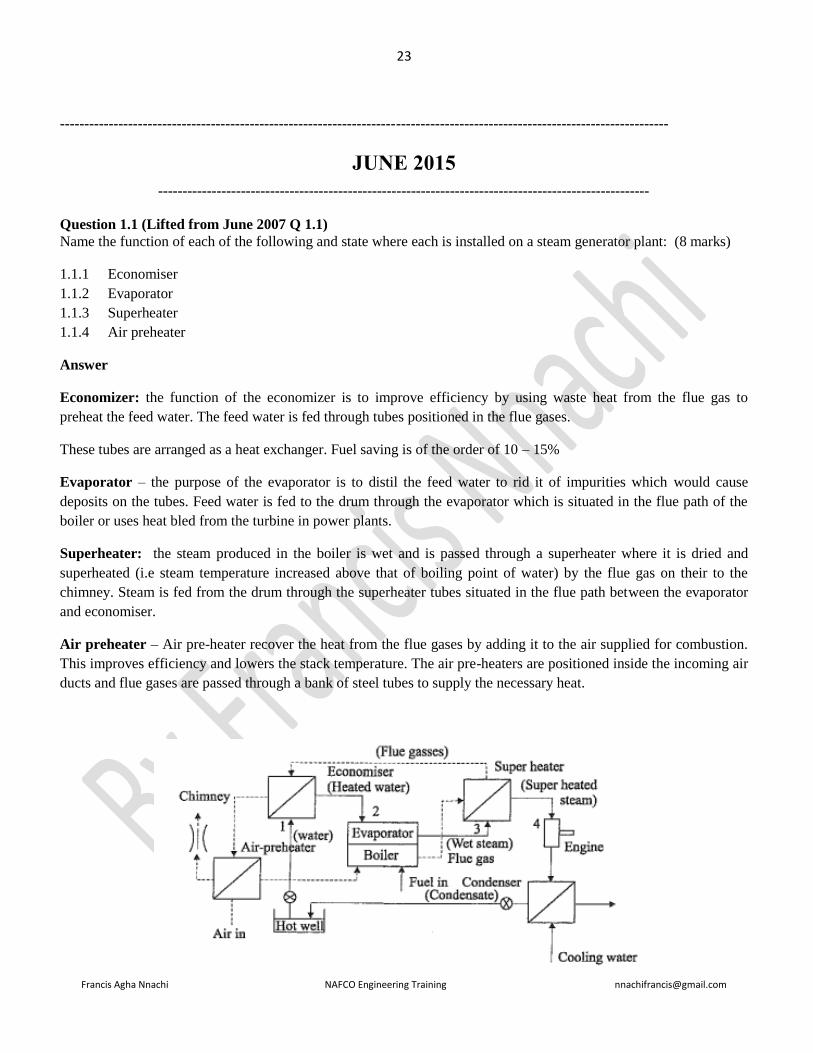
Name the function of each of the following and state where each is installed on a steam generator plant: (8 marks)
1.1.1 Economiser
1.1.2 Evaporator
1.1.3 Superheater
1.1.4 Air preheater
Answer
Economizer: the function of the economizer is to improve efficiency by using waste heat from the flue gas to
preheat the feed water. The feed water is fed through tubes positioned in the flue gases.
These tubes are arranged as a heat exchanger. Fuel saving is of the order of 10 – 15%
Evaporator – the purpose of the evaporator is to distil the feed water to rid it of impurities which would cause
deposits on the tubes. Feed water is fed to the drum through the evaporator which is situated in the flue path of the
boiler or uses heat bled from the turbine in power plants.
Superheater: the steam produced in the boiler is wet and is passed through a superheater where it is dried and
superheated (i.e steam temperature increased above that of boiling point of water) by the flue gas on their to the
chimney. Steam is fed from the drum through the superheater tubes situated in the flue path between the evaporator
and economiser.
Air preheater – Air pre-heater recover the heat from the flue gases by adding it to the air supplied for combustion.
This improves efficiency and lowers the stack temperature. The air pre-heaters are positioned inside the incoming air
ducts and flue gases are passed through a bank of steel tubes to supply the necessary heat.

24
Francis Agha Nnachi NAFCO Engineering Training [email protected]
Question 1.2 (Lifted from Nov. 2007 Q 1.2)
The primary cause of steam-generator problem is operational
Give FOUR characteristics of feed water for a typical industrial package fire-tube steam generator that should be
checked and indicate what the ideal values or condition should be. (4 marks)
Answer
Characteristics to be checked
1. Sediment & turbidity, organic matter; oil & grease
2. Hardneass, calcium (Ca) and magnesium (Mg)
3. Sodium, alkalinity, NaoH, NaHCO3, Na2CO3, sulphates (SO4); chlorides, Cl;
4. Iron (Fe) and manganese (Mn); silica (Si)
5. Ideal values or conditions
6. Feed water-boiler pressure: 69 –103.4
7. Dissolved oxygen (measured before oxygen scavenger addition) : 0.007
8. Total iron-mg/l: 0.01
9. Total copper: 0.01
10. Total hardness (CaCO3): not detectable
11. Non-Volatile TOC: 0.2
12. Oily matter: 0.02
13. pH at 25: 9.0 – 9.6
Question 2.2 (Lifted from Nov. 2010 Q 2.3)
South Africa is predominantly dependent on coal power generation for electricity. Name FIVE alternative energy
sources for generating electricity. (5 marks)
Answer:
1. Sun (solar energy)
2. Wind (wind energy)
3. Water (hydro power)
4. Nuclear energy
5. Tidal energy
6. Ocean wave energy
Question 3.1 (Lifted from Nov. 2006 Q 3.1; Nov. 2010 Q 3.1, June 2012 Q 3.1, June 2014 Q 3.1)
A health and safety management system (OHSMS) prescribed by the chief inspector in Government Notice R 859 of
2 September 2005 requires that you must establish an occupational health and safety policy for your factory. The
policy shall clearly state the overall health objectives and a commitment to improve health and safety performance.
Name FIVE requirements of the policy (5 marks)
Answer
OH&S Policy requirement

25
Francis Agha Nnachi NAFCO Engineering Training [email protected]
Ensure that the policy
a) is appropriate to the nature and scale of the organization’s OH&S risks;
b) includes a commitment to prevention of injury and ill health and continual improvement in OH&S management
and OH&S performance;
c) includes a commitment to at least comply with applicable legal requirements and with other requirements to which
the organization subscribes that relate to its OH&S hazards;
d) provides the framework for setting and reviewing OH&S objectives;
e) is documented, implemented and maintained;
f) is communicated to all persons working under the control of the organization with the intent that they are made
aware of their individual OH&S obligations;
g) is available to interested parties;
h) is reviewed periodically to ensure that it remains relevant and appropriate to the organization.
i) signed by the CEO
j) prominently displayed
Question 3.2 (Lifted from Nov. 2011 Q 3.2; Nov 2006 Q 3.3; June 2009 Q 3.2 Nov. 2010 Q 3.2)
The occupational health and safety management system (OHSMS 18002: 2000) – Guidelines for the implementation
of OHSAS 18001, is a guideline for the implementation of OHSAS 18001.
Name SEVEN typical inputs that should be considered as part of the planning phase (7 marks)
Answer
• Hazard identification, risk assessment and determining controls
• Legal and other OH&S requirements
• Competence, training and awareness
• Communication, participation and consultation
• Control of documents
• Operational control
• Emergency preparedness & response
• Performance measurement and monitoring
• Evaluation of compliance
• Incident investigation, nonconformity, corrective & preventive action
• Control of records
• Internal audit
Question 3.3 (lifted Nov 2012 Q 3.2; Nov. 2007 Q 3.3)
A risk assessment must be done before the replacement of a pole-mounted transformer with the minimum
interruption of customers. Name FOUR hazards associated with this type of work and discuss precautionary
measures for each of these hazards (8 marks)

26
Francis Agha Nnachi NAFCO Engineering Training [email protected]
Question 4.1 (Nov. 2011 Q 7.2; Q4.1 Nov. 2007)
A distribution board for an electrical installation needs to be installed in the change room and dining room. Name
THREE positions where the distribution board may not be mounted if it is not correctly IP-rated (3 marks)
Answer
According to SANS 10142-1 section 6.6.1.7 a distribution board shall not be mounted:
a). in a bathroom, except outside zone 3 ( and unless the enclosure provides an IP rating of IPX5)
b). above a fixed cooking appliance, or in a position where a stationary cooking appliance could be put below it,
(unless the enclosure provides a degree of protection of at least IP44)
c). within a radius of 1 m from a water tap or valve (in the same room), unless the enclosure provides a degree of
protection of at least IP44)
Answer
No Possible risks, hazards and danger Compulsory required precautionary measures
1 Physical electrical contact during testing.
a) All equipment used must adhere to OHSAct.
b) Use all test equipment according to prescribed procedures and
manuals.
c) Unauthorised access prohibited (Only PTM staff, barricading
tape, lock gates, etc.)
d) Ensure that plant is properly earthed and that the earthing
arrangement meets the requirement of the isolations at the
point where work has to be performed.
2
Possible explosion due to flammable gasses /
hazardous chemical substances: A pole
mounted distribution transformer would in all
likelihood have a hermetically sealed tank
containing flammable oil: this presents an
explosive hazard
Obtain gas test certificate prior to permit to work if necessary.
Always wear the appropriate personal protective equipment
including fire retardant clothing, hard hats, safety glasses and
rubber gloves
3 High elevated position. Compulsory use of safety belt / harness is required when the
possibility exists that a person can fall from an elevated position.
4 Slippery surfaces, oil spillages, leaks, etc.
a) All slippery surfaces to be cleaned before commencing
with work.
b) Avoid spillages.
5 Unsafe scaffolding.
a) Safe for use sign displayed.
b) Access ladder fitted.
c) No openings in platform.
d) Kick plates fitted.
e) Handrails fitted.
6
Personnel injury:
Components removal, such as a cover. The
cover could go out of control and hit the line
worker; this presents a falling hazard
Wear PPE: hard hats, safety glasses and rubber gloves.
7 Oil to skin contact (Skin irritation, etc.) Avoid oil to skin contact.
8 Unsafe conditions Report any unsafe act / condition
9 Work that needs to be performed above ground
level Complete Q-411 and send to SHEQ office

27
Francis Agha Nnachi NAFCO Engineering Training [email protected]
Question 4.2 (repeat Nov 2011 Q 7.3; June 2009 Q 5.2)
Name THREE requirements for the electrical installation of a water heater (3 marks)
Answer
• All water heater shall be bonded
• Dedicated circuits shall be provided for water heaters
• There may be more than one water heater on one circuit
• The electrical supply has the proper overload fuse or circuit breaker protection
• Wire sizes and connections comply with all applicable codes
• Wiring is enclosed in approved conduit
• The water heater and electrical supply are properly grounded
Question 4.3 (Lifted from Nov 2011 Q 7.4; June 2009 Q 5.3)
Name FOUR locations where a suspended luminaire must be out of arm’s reach from the floor (4 marks)
Answer
1. washroom
2. change room
3. laundry
4. cupboard or other enclosure
5. position exposed to wind & weather
Question 5.1
An eroded valve in a 200 mm slurry pipeline needs to be replaced
5.1.1 Name SIX considerations that must be taken into account when ordering a new valve (6 marks)
5.1.2 Name FOUR valve types that you will consider for this application (4 marks)
Answer
Question 7.2
Name TWO type of loads that helical spring can be used for (2 marks)
Answer
Question 7.3
A new stainless steel heat exchanger has developed severe cracks around the outlet. Name FOUR possible causes for
these cracks and discuss each cause (8 marks)
Answer

28
Francis Agha Nnachi NAFCO Engineering Training [email protected]
--------------------------------------------------------------------------------------------------------
NOVEMBER 2014
-------------------------------------------------------------------------------------------------------
Question 1.2 (repeat of Nov. 2010 Q 1.1; Nov. 2006 Q 1.1)
Name FIVE possible problems to be checked during an internal inspection on a steam generator by the inspector and
give the corrective measures to be undertaken for each problem by the user. (10 marks)
Answer
• Corrosion or cracking of tube sheets, tube ends, furnaces, drums etc
• Cracked fittings: repair all cracked fittings
• Erosion
• Scale and deposit: Remove scales and deposits in tubes or the space between the tubes. Internal feed pipes,
dry pans, scrubbers, baffles, chemical feed pipes, surface blowoff and bottom blowdown connections, and
other accessories shall be examined to see that their openings and perforations are free from deposits
• Broken stays
• Signs of leaking
• Excessive thinning of tubes from repeated rolling (thin places in the drum)
• Grease, oil or similar deposits: Examine the upper half of drums in the steam space for signs of grease, oil,
or similar deposit and clean
• Loose connections of all interior fittings
• Damaged or missing gaskets of all interior fittings
• Fusible plugs damage: Renew fusible plugs, if fitted
Question 2.2
Name FOUR methods of cooling oil-filled power transformers. (4 marks)
Answer
• Air
• Gas
• Synthetic mineral oil
• Solid insulation
Question 2.3
Name TWO types of insulation material used in an oil-filled power transformer (2 marks)
Answer

29
Francis Agha Nnachi NAFCO Engineering Training [email protected]
Question 3.1
An occupational health and safety management system (OHSMS) prescribed by chief inspector in government notice
R.859 of 2 September 2005 requires that the organisation shall establish, implement and maintain procedures for the
on-going hazard identification, risk assessment and determination of necessary control. The procedures for hazard
identification and risk assessment shall take into account the routine and non-routine activities.
Question 3.1.1
Name SEVEN other elements that the procedures for hazard identification and risk assessment shall also take into
account (7 marks)
Answer
The procedure(s) for hazard identification and risk assessment shall take into account:
a) Routine and non-routine activities;
b) Activities of all persons having access to the workplace (including contractors and visitors);
c) Human behaviour, capabilities and other human factors;
d) Identified hazards originating outside the workplace capable of adversely affecting the health and safety of
persons under the control of the organization within the workplace;
e) Hazards created in the vicinity of the workplace by work-related activities under the control of the organization;
f) Infrastructure, equipment and materials at the workplace, whether provided by the organization or others;
g) Changes or proposed changes in the organization, its activities, or materials;
h) Modifications to the OH&S management system, including temporary changes, and their impacts on operations,
processes, and activities;
i) Any applicable legal obligations relating to risk assessment and implementation of necessary controls
j) The design of work areas, processes, installations, machinery/equipment, operating procedures and work
organization, including their adaptation to human capabilities.
Question 3.1.2
When determining controls or considering changes to existing controls, which FIVE considerations, in the correct
order, shall be given to reduce the risks? (5 marks)
Answer
Having completed a risk assessment and having taken account of existing controls, the organization should be able to
determine whether existing controls are adequate or need improving, or if new controls are required.
The following provides examples of implementing the hierarchy of controls:
• Elimination – modify a design to eliminate the hazard, e.g. introduce mechanical lifting devices to eliminate
the manual handling hazard;
• Substitution – substitute a less hazardous material or reduce the system energy (e.g. lower the force,
amperage, pressure, temperature, etc.);
• Engineering controls – install ventilation systems, machine guarding, interlocks, sound enclosures, etc.;
• Signage, warnings, and/or administrative controls – safety signs, hazardous area marking, photo‑luminescent signs, markings for pedestrian walkways, warning sirens/lights, alarms, safety procedures,
equipment inspections, access controls, safe systems of working, tagging and work permits, etc.;
• Personal protective equipment (PPE) – safety glasses, hearing protection, face shields, safety harnesses
and lanyards, respirators and gloves.

30
Francis Agha Nnachi NAFCO Engineering Training [email protected]
Question 3.2
You have a production line for the casting of leads plates that are used for lead acid batteries. Name FOUR
hazards associated with the casting of lead plates and state the controls you will introduce to reduce the risk to
a person’s safety and health. (8 marks)
Answer
Question 4.1 (lifted from June 2012 Q 7.2; Q 4.1 Nov. 2007)
Name FOUR requirements for the positioning of distribution boards in an electrical installation (4 marks)
Answer
Electrical equipment shall be so positioned that
1. it does not impair the functioning or safety of other equipment,
2. it is readily accessible for installation, replacement, operation, testing, inspection, maintenance and
repair. All parts of the installation shall be accessible without the need to enter any adjoining premises
(for example, in an apartment building), NOTE Common areas (such as passages and entrance halls) are
not regarded as adjoining areas.
3. there is easy access to its location,
4. it is not likely to be physically damaged
5. dust or moisture is not likely to accumulate on live or other parts and cause flashover, and
6. Where the distribution board is concealed by a cupboard or other covering, the notice for live electrical
apparatus referred to in annex Q shall be in a conspicuous place indicating the position of the
distribution board.
Question 4.2 (repeated: Q 7.4 June 2012 ;Q 5.2 Nov. 2010; Q7.2 Nov. 2007)
State FIVE visual inspections to be carried out as well as FIVE tests on the test report according to the SANS
10142-1: wiring code of practice for an electrical installation to ensure a valid certificate of compliance.
(10 marks)
Answer
During the inspection, confirm that
17) accessible components are correctly selected
18) all protective devices are of the correct rating,
19) all protective devices are capable of withstanding the prospective short-circuit current
20) Conductors are of the correct rating and current-carrying capacity for the protective devices and connected
load (Pay attention to voltage rating, voltage drop, current-carrying capacity and short-circuit
capacity.)
21) components have been correctly installed, and are accessible where necessary
22) disconnecting devices (isolators) are correctly located and that all switchgear switches the phase conductors,
23) Different circuits are separated electrically. Circuits for control communication, security, detection, safety
and the like, should be electrically separated and, where specified, physically separated,

31
Francis Agha Nnachi NAFCO Engineering Training [email protected]
24) connections of conductors and earthing and bonding are mechanically sound,
25) connections of conductors and earthing and bonding are electrically continuous,
26) Circuits, fuses, switching devices, terminals, earth leakage units, circuit-breakers and distribution boards
are correctly and permanently identified, marked or labelled, [Pay attention to installations where
circuit-breakers are used in series-connected (cascaded) systems].
27) the integrity of the fire barrier has been maintained where an electrical system passes through a fire
barrier,
28) safety lighting, emergency lighting and safety signs function correctly,
29) The installation including all accessible compoenets should comply with SANS 10142-1
30) the installation complies with the general safety principles of this edition of this part of SANS 10142
and is reasonably safe
31) where an alternative supply is installed, it complies with all the requirements in 7.12, and
32) the position of the readily accessible earthing terminal for the earth connection of other services made by
installers of such services
Testing
1. Continuity of bonding
2. Resistance of earth continuity conductor
3. Continuity of ring circuits
4. Earth fault loop impedance at the main switch
5. Elevated voltage on supply neutral
6. Earth resistance
7. Insulation resistance
8. Voltage, main distribution board — no load
9. Voltage, main distribution board — on load
10. Voltage at available load
11. Operation of earth leakage units
12. Earth leakage test button
13. Polarity at points of consumption
14. Switching devices
Question 5.2
Give THREE common reasons for the failure of bearings (3 marks)
Answer
Question 5.3
Give FIVE warnings of a damaged or deteriorated bearing (5 marks)
Answer
Question 6.2 (Lifted from June 2011 Q 7.2)

32
Francis Agha Nnachi NAFCO Engineering Training [email protected]
Your new plant is supplied by an 11 kV overhead power line. The voltage is reduced to 400 V in the substation. Give
TEN safety checks for the MV part of the installation on the test report that should be done before a certificate of
compliance can be issued. (10 marks)
Answer
Equipment of the new, extended or reconstructed installation
1. Do the components specified comply with applicable standards
2. Have all components be type tested to the applicable standards
3. Are the type-test report still valid
4. Have the design of components not covered by type-test reports been verified by the registered professional
person
5. Are applicable routine test report available for the components of the new, extended or rewired installation
6. Are equipment and maintenance instructions available on site
7. Are the conductor of the current-carrying capacity
8. Are disconnecting devices correctly located
9. Are the connections of all conductors, including earthing mechanically sound & electrically continuous
10. Has the phasing of all circuits been performed
11. Are power cables of different voltages, control & communication cables correctly separated
12. Have the appropriate short-circuit ratings & performance rating of switchgear been verified
13. Have the correct fault rating, coordination & certification of fuses been verified etc
Protection design and settings
14. Has a schedule of all protection settings be provided
15. Has surge protection be correctly designed and installed
16. Is the battery supply for the system protection, where applicable, of sufficient capacity
17. Have all protection, alarm and indicating devices been commissioned (e.g Buchholz, oil temperature,
overcurrent and earth-fault relays, counters, auto-reclosers, maximum demand indication, etc.)
18. Where metering is provided, are the correct class and ratio of CTs provided
Substation design and construction
19. Are accesses and emergency exists visible at all time, marked and operational
20. Is perimeter fencing correctly positioned, secure against unauthorized entrance and bonded to the earthmat?
21. Are locks and keys of good quality at hand for all controlled entrances?
22. Is adequate ventilation provided for cooling?
23. Is the lighting for both normal and emergency operation in accordance wit prescribed levels?
24. Are there separation barriers and distances between MV and LV to specified requirements?
25. Is access to live parts sufficiently prevented?
26. Is drainage functional and adequate?
27. Are notices, safety signs, marking and labelling in accordance with prescribed requirements?
28. If it is required, does the fire fighting equipment comply with the local fire regulations
29. Has a logbook been provided for all events and switching?
30. Where applicable, have interlocking and lock-out facilities been provided?
31. Are laminated general arrangement and circuit diagram on prominent display?
32. Have all other potentially pollutant services been excluded from substations?
33. Where necessary, is the installation protected against damage by road and process vehicle?
Transformer
34. Is the oil sump adequately designed and positioned away from the transformer?
Earthing

33
Francis Agha Nnachi NAFCO Engineering Training [email protected]
35. Is the MV/LV earthing configuration in accordance SANS 10292?
36. Is the earth electrode, if present, designed in accordance with SANS 1063?
37. If a dedicated earth bar is installed, is it of the correct cross-sectional area?
38. If applicable, is type tested portable earthing gear available and well maintained?
39. Where substation earthing is provided, is each point accessible and indicated?
Question 7.2
Name FOUR checks that should be carried out on a chain during routine inspections. (4 marks)
Answer
Question 7.3
State FOUR advantages of using chains instead of wire ropes (4 marks)
Answer

34
Francis Agha Nnachi NAFCO Engineering Training [email protected]
----------------------------------------------------------------------------------------------------------------------------
JUNE 2014
-----------------------------------------------------------------------------------------------------------------------------------------
Question 1.1 (lifted from Q 1.3 Nov 2010; June 2010 Q 1.3; Nov 2011 Q 1.3)
You have a 10 ton fire-tube steam generator that uses coal at your plant. Name TEN items to be checked or to be
done every 8 hours on the steam generator. (10 marks)
Answer
Check the following:
1. boiler pressure
2. water level in the boiler
3. that the grate is not more than hand-hot and that its color is normal
4. ash build up under stoker via peephole in emergency de-aching door
5. note under grate damper setting
6. ignition of coal through the ignition arch peephole
7. that the coal is flowing correctly in the stoker hopper
8. that the ash trolley is empty. Replace ash trolley and open the ash valve to allow ash to drop into the ash
trolley, then close it
9. the length of the fire through the rear peephole. Adjust under grate damper setting if necessary
10. that the grit trolley is empty
11. that there are enough chemicals in the chemical dosing pump tank for your shift
12. that there is salt in the brine tank of the water softener
13. check the water level in the hot well tank
14. check the log-enter any defect found during handing over immediately
After the first 30 minutes of shift only: blow down both water gauges; blow down both Mobrey controls
Question 2.2 lifted from Nov. 2011 Q 2.2 ; June 2007 Q 7.3; Nov. 2009 Q 2.2)
Discuss common mistakes that cause wastage of electrical energy in electrical motors (6 marks)
Answer
• Operating electric motors under less than full load: Induction motors have distinct inefficiencies in that
they cannot effectively adjust the amount of electricity they consume for the work they do. When they
operate under less than full load, substantial power is wasted – a soft starter could be a consideration
• Operating electric motor without a power factor correction: A power factor less than unity results in the
following disadvantages:- Large kVA rating of equipment, greater conductor size, large copper losses, poor
voltage regulation, reduced capacity handling of the system
• Evaluating electric motor usage by load and not including operating hours: Two of the most important
concerns in evaluating energy usage are actual load and operating hours
• Not oversizing of electric motor to ensure load capability results

35
Francis Agha Nnachi NAFCO Engineering Training [email protected]
Question 3.1 (repeat Nov. 2006 Q 3.1; Nov. 2010 Q 3.1, June 2012 Q 3.1)
A health and safety management system (OHSMS) prescribed by the chief inspector in government notice R.859 of 2
September 2005 requires that you must establish an occupational health and safety policy. Name FIVE requirements
that should be contained in the employer’s OHS policy (5 marks)
Answer
OH&S Policy requirement
Ensure that the policy
a) is appropriate to the nature and scale of the organization’s OH&S risks;
b) includes a commitment to prevention of injury and ill health and continual improvement in OH&S management
and OH&S performance;
c) includes a commitment to at least comply with applicable legal requirements and with other requirements to which
the organization subscribes that relate to its OH&S hazards;
d) provides the framework for setting and reviewing OH&S objectives;
e) is documented, implemented and maintained;
f) is communicated to all persons working under the control of the organization with the intent that they are made
aware of their individual OH&S obligations;
g) is available to interested parties;
h) is reviewed periodically to ensure that it remains relevant and appropriate to the organization.
i) signed by the CEO
j) prominently displayed
Question 3.2 (Lifted from Nov 2011 Q 3.2; Nov 2006 Q 3.3; June 2009 Q 3.2
A 10 ton centrifugal press is used to make 10 mm holes in small 5 mm plates that are manually fed.
3.2.2 Name FIVE items or documents on the press to be considered for the planning stage of an OHMS (5 marks)
Answer
• Hazard identification, risk assessment and determining controls
• Legal and other OH&S requirements
• Competence, training and awareness
• Communication, participation and consultation
• Control of documents
• Operational control
• Emergency preparedness & response
• Performance measurement and monitoring
• Evaluation of compliance
• Incident investigation, nonconformity, corrective & preventive action
• Control of records
• Internal audit
3.2.2 Name FIVE hazards associated with such a press and give the precautionary measures to reduce the
hazard (10 marks)

36
Francis Agha Nnachi NAFCO Engineering Training [email protected]
Answer
Question 4.1 (lifted from June 2010 Q 5.1)
Name FOUR safety considerations to determine the nominal cross-sectional area of a conductor in an
electrical installation (4 marks)
Answer
SANS10142-1: 5.2.3 (page 72)
The nominal cross-sectional area of a conductor shall be determined in accordance with the following safety
considerations:
1. The conductor's maximum permissible continuous temperature;
2. The permissible voltage drop of an installation;
3. The electromechanical stresses and thermal effects that is likely to occur as a result of short circuits;
4. The maximum impedance of the conductor with respect to the functioning of the short-circuit protection; and
5. Mechanical stresses.
Question 4.2
Where may flexible cords be used in an electrical installation? (4 marks)
Answer
SANS10142-1: 6.1.11 (page 84)
Flexible cords shall not be used as part of the electrical installation, except where
a) Required by the relevant product solely for termination or connection of moving parts,
b) Specified in the product standard,
c) Used as single cores in conduits,
d) Used in an authorized wiring system, or
e) Needed for the connection of luminaires, provided that each connection is limited to one luminaire and to a
maximum length of 3 m
Question 4.3
What information must be on a multicore, extruded solid dielectric-insulated cable? (3 marks)
Question 4.4
Name TWO requirements for the marking of multicore, extruded solid dielectric-insulated cables (2 marks)
Question 4.5 (Repeat of Q 5.5 June 2010)
Name SEVEN requirements for outdoor storage of cable drums (7 marks)
Answer
• Drums should be stored on a hard surface at a slight angle and the area should have a drainage system
• Drums should be released on a “first in first out” basis
• Cable ends should be sealed at all times

37
Francis Agha Nnachi NAFCO Engineering Training [email protected]
• Stack flange-to-flange but if this is not possible limit vertical stacking practice to smaller drums only
• Stack in such a way that drums are easily accessible
• Observe fire protection rules
• Cable racks are ideal for storage but take care not to overload
• Cables must be identifiable at all times
• If drums are expected to be stored for a long time they must be specially treated or made of hard woodRotate
paper insulated cable drums one complete rev per annum.
Question 8.2
You have a battery room for the changing of forklift batteries that is classified as a zone 2 hazardous location.
Name FOUR types of protection that may be used on the electrical machinery (4 marks)
Answer
SANS 10108: 8.2.3 & 8.2.4 (page 21-22)
Electrical apparatus selected for use in a zone 2 location shall be limited to one of or a combination of the following
types
1. Flameproof (Ex d)
2. Specially protected (Ex s)
3. Increased safety (Ex e)
4. Encapsulated (Ex m)
5. Power-filled or sand-filled (Ex q)
6. Intrinsically safe (Ex “ia” or Ex “ib”)
7. Pressurized (Ex p) apparatus that has interlock that isolate it automatically when the fresh air supply or inert
gas supply fails
8. Non-sparking (Ex n)
9. Pressurized (Ex p) apparatus that has visual or adubile warning system to indicate failure of the fresh air
supply or inert-gas supply
Question 8.3
Name SIX areas where cathodic protection is successfully used (6 marks)
Answer
Question 8.4
Name FOUR areas where cathodic protection is not generally used (4 marks)
Answer
Cathodic protection is not generally used in the following instances:
• For protection against atmospheric corrosion or corrotion due to condensation
• In acid solutions
• For protection against steam or fumes
• In situations with a complicated geometry such as a bundle of condenser tubes, or in cramped environments
such as the inside of a small diameter pipeline.

38
Francis Agha Nnachi NAFCO Engineering Training [email protected]
----------------------------------------------------------------------------------------
NOVEMBER 2013
------------------------------------------------------------------------------------------------------------------
Question 3.1 (a repeat of Q 3.1 Nov 2012; Q 3.1 Nov 2007)
Behavioural safety depends on basic principles. Name EIGHT of these principles that will ensure effective
implementation of a system (8 marks)
Answer
1. Physical capabilities
2. Experience, and
3. Training
4. Engineering Controls,
5. Equipment,
6. Job task, and
7. The work culture
8. Behavior – what the person does on the job
Question 3.2 (A repeat of Q 3.2 June 2012, Q 3.2 Nov. 2007)
Name SIX outcomes of behavioural safety (6 marks)
Answer
Typical Outcomes
A well designed and executed Behavioral Safety process should lead to:
1. Reduced numbers of accidents or incidents, near misses and property damage
2. Improved levels of quantified safety behaviors
3. Reduced incident costs
4. Sustainability
5. Acceptance of the system by all concerned
6. The benefit will be far reaching
7. Increased reporting of defects, near misses, accidents
8. Improved Corrective Action rate
9. Improved people skills
10. Better Safety Leadership
Question 3.3
Name TEN examples of reactive monitoring of data in an organisation to prevent recurrence of incidents/accidents in
the workplace (5 marks)
Answer
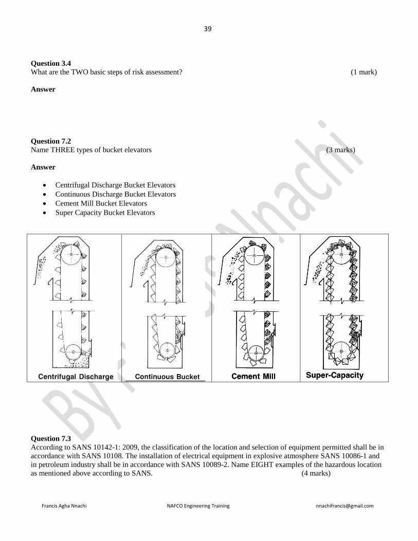
39
Francis Agha Nnachi NAFCO Engineering Training [email protected]
Question 3.4
What are the TWO basic steps of risk assessment? (1 mark)
Answer
Question 7.2
Name THREE types of bucket elevators (3 marks)
Answer
• Centrifugal Discharge Bucket Elevators
• Continuous Discharge Bucket Elevators
• Cement Mill Bucket Elevators
• Super Capacity Bucket Elevators
Question 7.3
According to SANS 10142-1: 2009, the classification of the location and selection of equipment permitted shall be in
accordance with SANS 10108. The installation of electrical equipment in explosive atmosphere SANS 10086-1 and
in petroleum industry shall be in accordance with SANS 10089-2. Name EIGHT examples of the hazardous location
as mentioned above according to SANS. (4 marks)

40
Francis Agha Nnachi NAFCO Engineering Training [email protected]
Answer
SANS10142-1: 7.14 (page 265) Hazardous locations
10. Petrol pumps
11. Spray painting booths
12. Areas for the storage, mixing and use of flammable fuels, paints or solvents
13. Grain silos and flour mills
14. Coal storage facilities
15. Wine cellars
16. Areas for the storage and filling of LPG cylinders
17. Battery charging locations
18. Sewage plant
Question 7.4
People, animals and property should be protected against harmful earth fault currents by means of protective
measures. What are FOUR earth fault current protective measure that can be used? (4 marks)
Answer
SANS 10142: 5.1.3.2 (page 70)
Earth fault current protective measures are:
• Earthing and bonding
• Electrical separation of circuits
• The use of an isolating transformer with an output of 50 V or less
• The use of electrical equipment that is double insulated or
• The use of earth leakage protection for socket-outlet circuits
Question 7.5
There are types of wiring and methods of installations based on SANS 10142-1; 2009. Name FOUR factors to keep
in mind before installation can be done (2 marks)
Answer
SANS10142: 5.2.4 (page 72)
• The location
• The nature of the building elements for supporting the wiring
• The accessibility of the wiring to persons and livestock
• The voltage
• The electromechanical stresses and thermal effects likely to occur as a result of short-circuits; and
• Stress imposed on the wiring during installation and in service

41
Francis Agha Nnachi NAFCO Engineering Training [email protected]
=================================================================================
JUNE 2013
=================================================================================
Question 2.2 (Repeated Nov. 2013 Q 2.2)
List THREE types of earth electrodes (do not include a water reticulation system) and briefly describe the
advantages and disadvantages of each type. (3 x 2) (6 marks)
Answer
Three types of earth electrode
commonly used are
Advantages Disadvantages
1. Buried earth plate
comprising a thin metal
sheet 3 to 6 mm thick made
as large as practicable and
buried as deep as considered
practicable.
a. Only advantage may lie in
small excavation if
conductivity is high
a. Large excavation may be
necessary to obtain
sufficiently low resistance
b. Excavation may not reach
water-table
2. Trench earth, comprising a
length of solid or stranded
conductor say 70 mm2
section buried in an
excavated trench.
a. Contact is made over a large
area, lowering the reistance
between the electrode and
main body of earth.
b. Conductors is more
economically used than if
made into an earth mat
c. Trench excavation for other
purposes may be used
a. Trench depth may not reach
the water-table
b. Special trench may be
necessary
3. Earth spike comprising
sections screwed to each
other in turn and driven
vertically into the
a. Contact is made with large
volume of earth
b. Electrode may be driven
down to water table
a. Special equipment necessary
for driving in hard ground
NOTE: Reasons for exclusion of water reticulation are:
1. Danger to workmen removing a water meter etc.
2. Use of non-metallic piping for water
3. Non-conducting coatings to water piping
4. Non-conducting joints in water piping
5. Sacrificial corrosion of ferrous piping when electricity connected to non-ferous earth electrodes such as
copper
Question 3.1 (Repeated June 2016 Q 3.1)
As an engineer, part of your responsibility is a large electrical workshop. List TEN general points which are
important with regard to safety in the workshop (5 marks)

42
Francis Agha Nnachi NAFCO Engineering Training [email protected]
Answer
• Visible notices and signs as required by regulations and standards
• Workplace free from hazards
• Floors free from tripping and slipping
• Machinery operated and maintained to manufacturer’s instructions
• All controls and emergency devices are working correctly
• Sufficient ventilation
• Health and safety meetings are held
• Fitness of all workers to perform work
• Supply of PPE are worn by workers
• Adequate guarding & ensure that dangerous places are protected
Question 3.2
What are SIX steps that need to be followed when analysing risk in the workplace (3 marks)
Answer
1. Identify the hazard
2. Access and prioritize the risk
3. Decide on control measures
4. Implement control measures
5. Monitor and
6. review
Question 3.3
Name THREE forms of risk assessments (3 marks)
Answer
1. Baseline risk assessment
2. Issue base
3. Continues
Question 3.4 (repeated June 2016)
Name FOUR reasons why the plant engineer must manage risk in the working environment (2 marks)
Answer:
• To assist in identifying the risks
• Assist with the evaluation of the risks
• Assist with control measures to mitigate the risks
• Assist with financial recommendations
Question 3.5 (repeated June 2016 Q3.5)
There are two groups of root causes of accidents in the workplace. They are classified as personal and job related
Name FIVE of each group (5 marks)

43
Francis Agha Nnachi NAFCO Engineering Training [email protected]
Answer:
1 - Personal Factors:
• Lack of knowledge / skill (Training)
• Improper motivation
• Physical / Mental problems
• Inadequate capability
• Stress
2 – Job Related:
• Inadequate engineering
• Inadequate purchasing
• Inadequate tools / Equipment
• Wear and Tear
• Inadequate maintenance
• Improper instruction / Inadequate work standards
• Abuse or misuse
Question 3.6
Risk can be identified through macro or micro hazards
Give FOUR suitable and sufficient risk assessments. (2 marks)
Answer:
a) Should consider all the risks that could arise
b) Should enable manager to develop and implement the systems
c) Should be appropriate to the nature of the work
d) Should remain valid for a reasonable period or time
Question 7.2
Name SIX conductors that may be connected to the earth busbar according to SANS 10142-1: 2003 N.2.3. (3 marks)
Answer
1. all exposed conductive parts of an installation
2. all conductive cable sheaths and armouring, wireways and catenary wires;
3. the earthing terminal of a socket-outlet;
4. the secondary winding of a transformer if it is not a safety transformer;
5. earthing terminals of all permanently connected electrical equipment and appliances;
6. conductive parts of discharge luminaires and equipment that need special earthing arrangements; and
7. all class I equipment

44
Francis Agha Nnachi NAFCO Engineering Training [email protected]
Question 7.3
Name EIGHT conductors that shall be connected to the main earthing terminal in every installation where main
equipotential bonding used. (4 marks)
Answer
In every installation where main equipotential bonding is used, the following shall be connected to the main earthing
terminal in the distribution board:
1) Main equipotential bonding
2) Earthing conductors;
3) Bonding conductors,
4) Functional earthing conductors
5) Conductive screens, sheaths or armouring of telecommunication cables or telecommunication equipment;
6) Earthing conductors for overvoltage protective devices (including conductors of lightning protection systems);
7) Earthing conductors of radio antenna systems; and
8) The earthing conductor of d.c. power supply system for IT equipment.
Question 7.4
What does the formula I = Is x F1 x F2 x F3 x F4 A determine (1 mark)
Answer
The formula determines the sustained current-carrying capacity I (A) of a cable buried directly in the ground
Question 7.5
Indicate what each variable in the equation stands for (3 marks)
Answer
The sustained current-carrying capacity I (A) of a cable buried directly in the ground can be calculated by the
following equation:
𝐼 = 𝐼𝑠 × 𝐹1 × 𝐹2 × 𝐹3 × 𝐹4
Where
𝐼𝑠 is the standard rating in amperes
𝐹1 is the rating factor for depth of burial
𝐹2 is the rating factor for soil temperature at depth of burial
𝐹3 is the rating factor for thermal resistivity of soil
𝐹4 is the rating factor for grouping of directly buried cables that are thermally interdependent

45
Francis Agha Nnachi NAFCO Engineering Training [email protected]
=================================================================================
NOVEMBER 2012
==================================================================================
Question 2.1
Give FOUR advantages and FOUR disadvantages of earthing the neutral
Answer
Advantages of Neutral grounding
1. Voltages of the healthy phases do not exceed line to ground voltages i.e they remain nearly constant
2. The high voltage due to arcing ground are eliminated or in other word, the system eliminates arcing ground
faults since it is solidly earthed
3. The protective relays can be used to provide protection against earth faults.
4. The over-voltages due to lightning are discharged to earth
5. It provides greater safety to personnel and equipment
6. It provides improved service reliability
7. Operating and maintenance expenditures are reduced
Disadvantages of Neutral grounding
1. The system experiences higher fault currents than in the insulated neutral system
2. The earth connection must be made at all points thereby increasing the system capital cost. All points from
the substation to the equipment, must be earthed
3. Fast isolation is essential to limit the switching voltages
Question 3.1 (repeated Nov 2007 Q 3.1)
Behavioral safety depends on basic principles. Name EIGHT of these principles that will ensure effective
implementation of a system (8)
Answer
9. Physical capabilities
10. Experience, and
11. Training
12. Engineering Controls,
13. Equipment,
14. Job task, and
15. The work culture
16. Behavior – what the person does on the job

46
Francis Agha Nnachi NAFCO Engineering Training [email protected]
Question 3.2 (repeat of Q3.3 Nov. 2007)
A risk assessment must be done before the replacement of a pole mounted transformer with minimum interruption to
customers. Name SIX hazards associated with this type of work and discuss precautionary measures for each of these
hazards (6)
Answer
No Possible risks, hazards and danger Compulsory required precautionary measures
1 Physical electrical contact during
testing.
e) All equipment used must adhere to OHSAct.
f) Use all test equipment according to prescribed
procedures and manuals.
g) Unauthorised access prohibited (Only PTM
staff, barricading tape, lock gates, etc.)
h) Ensure that plant is properly earthed and that
the earthing arrangement meets the requirement
of the isolations at the point where work has to
be performed.
2
Possible explosion due to flammable
gasses / hazardous chemical
substances: A pole mounted
distribution transformer would in all
likelihood have a hermetically sealed
tank containing flammable oil: this
presents an explosive hazard
Obtain gas test certificate prior to permit to work if
necessary.
Always wear the appropriate personal protective
equipment including fire retardant clothing, hard
hats, safety glasses and rubber gloves
3 High elevated position.
Compulsory use of safety belt / harness is required
when the possibility exists that a person can fall
from an elevated position.
4 Slippery surfaces, oil spillages, leaks,
etc.
c) All slippery surfaces to be cleaned before
commencing with work.
d) Avoid spillages.
5 Unsafe scaffolding.
f) Safe for use sign displayed.
g) Access ladder fitted.
h) No openings in platform.
i) Kick plates fitted.
j) Handrails fitted.
6
Personnel injury:
Components removal, such as a cover.
The cover could go out of control and
hit the line worker; this presents a
falling hazard
Wear PPE: hard hats, safety glasses and rubber
gloves.
7 Oil to skin contact (Skin irritation,
etc.) Avoid oil to skin contact.
8 Unsafe conditions Report any unsafe act / condition
9 Work that needs to be performed
above ground level Complete Q-411 and send to SHEQ office

47
Francis Agha Nnachi NAFCO Engineering Training [email protected]
Question 3.3
State 12 relevant records that should be kept and are used to demonstrate conformance to the requirements of the
legislation based on safety. (6)
Answer
Records that can demonstrate conformance to the requirements include:
1. records of the evaluation of compliance with legal and other requirements,
2. hazard identification, risk assessment and risk control records,
3. records of the monitoring of OH&S performance,
4. calibration and maintenance records for equipment used to monitor OH&S performance,
5. records of corrective action and preventive action,
6. reports of OH&S inspections,
7. training and associated records that support evaluations of competence,
8. OH&S management system audit reports,
9. participation and consultation reports,
10. incident reports,
11. incident follow‑up reports,
12. OH&S meeting minutes,
13. health surveillance reports,
14. personal protective equipment (PPE) maintenance records,
15. reports of emergency response drills,
16. management review records
Question 6.2
Draw up a code of practice for the maintenance of an air compressor for both reciprocating and turbo compressor. (8)
Answer
Maintenance
Electrical
• Check all ammeter and voltage readings
• Check the power factor readings
• Check the exciter brushes for sparking
• Check the condition of brushes on slip rings
• Check the condition of the tripping batteries on voltmeter.
• Check all indicator flags and lights
• Check that all auxiliary units are running and in order.
• Check the recorder printout for any alarms recorded.
• Earth leakage trip testing to be carried out on three monthly basis on the control panel.
• Infra-red scanning to be done by a professional company on yearly basis on the busbars
• Cooling Tower
• Check that the sprays and water spreaders are working satisfactory.
• Treat the cooling water as per the engineer’s instructions. Good control is essential for efficiency and to
reduce the workload of cooler cleaning.
Mechanical
Weekly
• Take samples of cooling water and send to laboratory for analysis.
Monthly

48
Francis Agha Nnachi NAFCO Engineering Training [email protected]
• Check the condition of the suction screens and clean if necessary.
• Check the oil level in the gearbox by removing one set screw from the top of the gearbox and visually
check the correct amount of oil at this point; the uppermost gears must be covered.
• Grease the bearings in the water spreader.
• Check that the water slots are clear of scale or any foreign objects.
Six (6) Monthly
• Drain and clean the pond or dam and refill with clean water.
• Check and clean cooling water pump suction screens.
• Add the required chemical charge before restarting.
Yearly
• Brush–clean fan blades, frame and check blades for cracks.
• Check if blades to hub bolts are secure. Maximum torque is 39 N/m.
• Repaint complete motor and frame with a suitable high resistant anti-corrosion paint.
Question 7.1
Name TEN visual inspection items in a hazardous location (5)
Answer
SANS10142 page 291 – additional test report for hazardous location
Visual Inspection
1. Is all explosion protected equipment correctly selected
2. Is all explosion protected equipment correctly installed
3. Is all explosion protected equipment correctly certified and documented?
4. Is all explosion protected equipment correctly labelled and marked?
5. Are all cable glands correctly selected and installed?
6. Is all equipment correctly protected against overload, overheating and incentive sparking
7. Are all intrinsically safe circuits at least 50 mm clear of, or well protected from, all power circuits?
8. Do all intrinsically safe circuits have adequate protection?
9. Are approved loop diagrams available for all intrinsically safe circuit?
10. Are there sufficient earthing and bonding to all explosion protected equipment, exposed and extraneous
metal parts and structures in the hazardous areas to prevent incentive sparking caused by static electricity,
stray currents and lightning (see SANS 10086-1)? 11. Is all sleeve-piping sealed where it exits the harzadous locations?
Question 7.2
What are the FIVE requirements that will satisfy the measurement and tests of a medical location? (5)
Answer
This list is found on SANS10142-1 – 7.7.6 a) Test the functioning of the insulation-monitoring devices of IT systems and the audible and visual alarm system b) Verify the integrity of the components required (in 7.7.4.6.3) for equipotential bonding c) Take measures to verify that the supplementary equipotential bonding is in accordance with the standard
(7.7.4.6.1 and 7.7.4.6.2)
d) Measure the leakage current of the output circuit and of the enclosure of medical IT transformers in the no-load condition.
e) Verify compliance with the requirement of the standard (7.7.5.6) for safety power supply services.

49
Francis Agha Nnachi NAFCO Engineering Training [email protected]
=================================================================================
JUNE 2012
==================================================================================
Question 1.1 (repeated June 1993 Q1; Nov 2009 Q1.1)
In view of increasing fuel prices, it has become of prime importance to economise on the use of fuel and to practice
energy conservation. You are responsible for the steam generator plant consisting of three horizontal fire-tube steam
generators of which any two are generally on line to meet a load of 15t/h. The plant runs 24 hours/day, 7 day per
week. The plant is provided with good instrumentation.
Assuming that the unburnt losses are minimised and that the steam generator feed water is supplied from a de-aerator
at 105o C and that the steam generator exit flue gas temperature is 250o C.
1.1.1 What is the biggest single loss factor affecting the steam generator efficiency (1 mark)
1.1.2 How would you improve the steam generator efficiency by about 4% from 76% to 80% in the case of a coal-
fired generator? (13 marks)
Answer
(a)
The question does not indicate if the boilers are equipped with economisers or combustion air heaters. It does,
however, specify that the boilers are fire-tube type. In package form these boilers are generally, not supplied with
either economisers or combustion air heaters. Consequently this solution approaches the problem from that angle.
There are numerous, unavoidable ways in which boilers on range loose heat. Radiation through the shell and gas
passage covers is reduced by lagging, but is nevertheless present. Every time boiler water is dumped during the
essential, twice or thrice daily blowdown periods hot boiler water is discharged. Be that as it may, the major loss of
more or less usable heat is in the hot flue gas, which is exhausted after passing through the two or three heat transfer
passages (passes) in the boiler.
In oil and gas fired boilers combustion air masses can be controlled to a high degree of accuracy and precision. This
means that the mass of flue gas is kept to a practicable minimum and thus the quantity of heat energy contained in
the flue gas, for a given temperature, is minimised. Thus losses are kept to a minimum, as far as mass of flue gas is
concerned. In coal fired boilers there has to be an excess of combustion air, as the combustion of coal is a two stage
process; 2C + O2 2CO and then, with excess (secondary) air, 2CO + O2 2CO2. More air than the stoichlometric
mass will have to be supplied to ensure complete combustion and there will thus be a greater mass of flue gas than
the theoretical ideal. As a consequence of this more heat energy exists in the flue gas of a coal fired boiler (for an
equal gas temperature) than will be lost from an equivalent oil or gas fired boiler.
Obviously, it is this supply of heat in the flue gas which has to be the target in endeavours to improve boiler
efficiency. The proven methods of achieving this are the aforementioned economiser and combustion air heater (also
known as a pre-heater). Tube passes are arranged in the flue gas, after it exists the last set of gas passeges in the
boiler. Feedwater pumped through these passes, prior to entry to the water space of the boiler, which is effectively an
evaporator, extracts heat energy from the flue gas and in so doing the enthalpy of the water is increased (and the
temperature of the flue gas reduced). This means that more of the heat energy applied to the boiler water, in the
evaporator, can be used to provide latent heat of evaporations, i.e. produce more steam.
A heat exchanger is situated in the flue gas, down stream of the economiser and the combustion air is blown through
it, by the forced draught (FD) on the way to the furnace. This air extracts heat energy from the flue gas. This means
that heat energy released in the combustion of the fuel can raise the temperature of the products of combustion above
that reached with unheated combustion air. The effect of this is to compensate for the temperature rise in the water
entering the evaporator, as a result of the economiser effect, and drive more heat into the boiler water, per kg of flue
gas. (heat transfer is a function of a temperature differential – the greater the differential, the greater the heat transfer.
The economiser is situated before the air heater for reasons of temperature differentials, which are essential to the
flow of heat energy. Feed water, which is normally hot (although not as that quoted in the question, as at 105 oC the
dearator has to be pressurized, which is an inordinary stupid thing to do, because if the object is to get gases out of
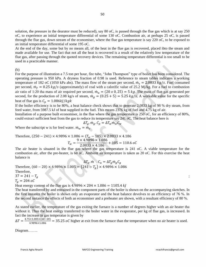
50
Francis Agha Nnachi NAFCO Engineering Training [email protected]
solution, the pressure in the dearator must be reduced), say 80 oC, is passed through the flue gas which is at say 250
oC, to experience an initial temperature differential of some 130 oC. Combustion air, at perhaps 25 oC, is passed
through the flue gas, down stream of the economiser, where the flue gas temperature is say 220 oC, to be exposed to
an initial temperature differential of some 195 oC.
At the end of the day, some but by no means all, of the heat in the flue gas is recovered, placed ibto the steam and
made available for use. The fact that not all the heat is recovered is a result of the relatively low temperature of the
flue gas, after passing through the quoted recovery devices. The remaining temperature differential is too small to be
used in a practicable manner.
(b)
For the purpose of illustration a 7.5 ton per hour, fire tube, “John Thompson” type of boiler has been considered. The
operating pressure is 950 kPa. A dryness fraction of 0.98 is used. Reference to steam tables indicates a working
temperature of 182 oC (1050 kPa abs). The mass flow of the steam per second, 𝑠 = 2.0833 𝑘𝑔/𝑠. Fuel consumed
per second, 𝑓 = 0.25 𝑘𝑔/𝑠 (approximately) of coal with a calorific value of 25.2 Mj/kg. For a fuel to combustion
air ratio of 1:20 tha mass of air required per second, 𝑎 = (20 𝑥 0, 25) = 5 𝑘𝑔. The mass of flue gas generated per
second, for the production of 2.08 kg/s of steam, 𝑔 = (0.25 + 5) = 5.25 𝑘𝑔/𝑠. A workable value for the specific
heat of flue gas is 𝐶𝑝 = 1.086𝑘𝐽/𝑘𝑔𝑘
If the boiler efficiency is to be 80%, a heat balance check shows that to generate 2,0833 kg of 98 % dry steam, from
feed water, from 5987.5 kJ of heat supplied in the fuel. This means 2376 kg of fuel and 4.75 kg of air.
Installation of a purpose built economiser, in the flue where the gas tempersture is 250 oC, for an efficiency of 80%,
could extract sufficient heat from the gas to reduce its tempersture say 241 oC. The heat balance here is
∆𝑇𝑔. 𝑔. 𝐶𝑝 = ∆𝑇𝑤𝑤𝐶𝑤
Where the subscript w is for feed water. 𝑤 = 𝑠
Therefore, (250 − 241) × 4.9896 × 1.086 = (𝑇𝑤 − 105) × 2.0833 × 4.186
𝑇𝑤 =9 × 4.9896 × 1.086
2.0833 × 4.186+ 105 = 110.6 𝑜𝐶
The air heater is situated in the flue gas where the gas temperature is 241 oC. A viable temperature for the
combustion air, after the pre-heater, is 60 oC. Ambient air temperature is taken as 20 oC. For this exercise the heat
balance is
∆𝑇𝑎 . . 𝐶𝑎 = ∆𝑇𝑔𝑔𝐶𝑔
Therefore, (60 − 20) × 4.9896 × 1.005 = (241 − 𝑇𝑔) × 4.9896 × 1.086
Therefore,
37 = 241 − 𝑇𝑔 ;
𝑇𝑔 = 204 𝑜𝐶
Heat energy content of the flue gas is 4.9896 × 204 × 1.086 = 1105.4 𝑘𝐽
The heat transferred by and entrained in the component parts of the boiler is shown on the accompanying sketches. In
the first instance the boiler is shown only an evaporator and the heat balance devolves to an efficiency of 76 %. In
the second instance the effects of both an economiser and a preheater are shown, with a resultant efficiency of 80 %.
As stated earlier, the temperature of the gas exiting the furnace is a number of degrees higher with an air heater tha
without it. Thus the heat energy transferred to the boiler water in the evaporator, per kg of flue gas, is increased. In
fact the increase in gas temperatue is given by
∆𝑇 =4.75×1.005×(60−20)
4.9896×1.086= 35.25 𝑜𝐶 higher at exit from the furnace than the temperature when no air heater is used.
Diagram……..

51
Francis Agha Nnachi NAFCO Engineering Training [email protected]
Question 3.1 (repeat Nov. 2006 Q3.1; Nov. 2010 Q3.1)
An occupational Health Safety Management system as prescribed by the chief inspector in the government
notification R.859 of 2 September 2005 requires that you establish an occupational health and safety (OHS) policy
for your factory. The policy should clearly state the overall health and safety objectives and a commitment to
improving health and safety performance.
State SEVEN requirements of the policy (7 marks)
Answer
OH&S Policy requirement
Ensure that the policy
a) is appropriate to the nature and scale of the organization’s OH&S risks;
b) includes a commitment to prevention of injury and ill health and continual improvement in OH&S management
and OH&S performance;
c) includes a commitment to at least comply with applicable legal requirements and with other requirements to which
the organization subscribes that relate to its OH&S hazards;
d) provides the framework for setting and reviewing OH&S objectives;
e) is documented, implemented and maintained;
f) is communicated to all persons working under the control of the organization with the intent that they are made
aware of their individual OH&S obligations;
g) is available to interested parties;
h) is reviewed periodically to ensure that it remains relevant and appropriate to the organization.
i) signed by the CEO
j) prominently displayed
Question 3.2 (a repeat of Q 3.2 Nov. 2007)
Name SIX outcomes of behavioural safety (6 marks)
Answer
Typical Outcomes
A well designed and executed Behavioral Safety process should lead to:
• Reduced numbers of accidents or incidents, near misses and property damage
• Improved levels of quantified safety behaviors
• Reduced incident costs
• Sustainability
• Acceptance of the system by all concerned
• The benefit will be far reaching
• Increased reporting of defects, near misses, accidents
• Improved Corrective Action rate
• Improved people skills
• Better Safety Leadership
Question 3.3
Compile a safety procedure before entering an ammonia plant and before switching operations may take place (7
marks)
Answer

52
Francis Agha Nnachi NAFCO Engineering Training [email protected]
1. Wear the appropriate PPE for the job task
2. Wear an air-supplying respirator if you will be entering an area that has high ammonia concentrations. If
your workplace stores large amounts of ammonia make sure that “escape” respirators with supplied air are
available to you in case of an accidental release. Know where these respirators are located and how to use
them
3. wear gloves to protect your skin
4. wear splash goggles or consider a face shield to protect your eyes
5. identify source of the electrical energy
6. identify shut-off for the source
7. Notify all persons that the machine must be switched off, locked out and tagged out.
8. Shut off energy source and lock switchgear in off position & hold the key
9. Test equipment to make sure they are de-energized
10. Earth the equipment
11. Apply tag to alert either workers that source equipment has been locked out
12. Make sure everyone is safe and accounted for before equipment is unlocked and turned back
Question 7.1
Name SIX explosion protection techniques used in explosive gas atmosphere (3 marks)
Answer
i. Flame arrestors
ii. Intrinsically safe electrical equipment
iii. Material/Equipment zoning and separation
iv. Heat/smoke/fire detection
v. Adequate ventilation
vi. House keeping
Answer from another source
Explosion-protection techniques – techniques applied to the design of electrical equipment, components and systems
to prevent the electrical energy from becoming an ignition source in the presence of flammable vapours and gases or
combustible dusts in explosive atmospheres. See Explosion-protected equipment.
Explosion-protected equipment – electrical equipment to which specific measures are applied to avoid ignition of a
surrounding explosive atmosphere.
Such equipment employs one or more of the following explosion-protection techniques;
Gas atmospheres
Ex d – flameproof;
Ex e – increased safety;
Ex i – intrinsic safety;
Ex n – non-sparking;
Dust
Ex i – intrinsic safety;
Ex t – enclosed;
Ex p – pressurisation;
Pressurisation
Ex p – pressurisation;
Flameproof enclosures
Ex d – flameproof (enclosures);
Coal mining (group I equipment)

53
Francis Agha Nnachi NAFCO Engineering Training [email protected]
Ex dI – flameproof;
Ex eI – increased safety;
Ex iI – intrinsic safety;
Ex t – enclosed (for dust);
Others
Ex o – oil immersion;
Ex m – encapsulation (hermetic sealed);
Ex s – special protection;
Ex v – ventilation;
Ex iD – intrinsic safety (for dust);
Ex mD – encapsulation (for dust);
Ex pD – pressurisation (for dust).
Answer from another source
code
Oil immersion o Type of protection where electrical
equipment is immersed in a
protective liquid in such a way that
an explosive atmosphere that may be
above the liquid or outside the
enclosure cannot be ignited e.g
transformer
Pressurized p This type of protection prevents the
surrounding atmosphere from
entering an enclosure by maintaining
a positive pressure within the unit e.g
switching & control cabinet, large
motor
Powder filled q Electrical parts are surrounded with
powder e.g quartz to prevent contact
with an explosive atmosphere e.g
capacitors, fuse etc
Flame proof d Enclosure housing electrical
equipment which, if there is an
internal explosion, will not ignite
surrounding atmosphere e.g control
panels, motor starter, motors, light
fittings
Increased safety e Additional methods are used to
eliminate arcs, sparks and hot surface
capable of igniting flammable
atmosphere e.g. terminal and
connection boxes, light fittings,
squarrel cage motors
Intrinsic safety Ia ib Electrical energy in equipment is
limited so that circuits cannot ignite
on atmosphere by sparking or
heating e.g. equipment e.g sensors,
instruments

54
Francis Agha Nnachi NAFCO Engineering Training [email protected]
Encapsulation m Electrical components embedded in
approved material tp prevent contact
with explosive atmosphere e.g
measurement & control devices,
solenoid valves, electrical
components enclosed in a resin
Type of protection ‘n’ n Non arcing and non-sparking e.g
terminal boxes, light fittings
Question 7.2 (repeated: Q4.1 Nov. 2007, Nov. 2014 Q 4.1)
State FIVE requirements for the positioning of electrical equipment in an electrical installation (5 marks)
Answer
Electrical equipment shall be so positioned that
7. it does not impair the functioning or safety of other equipment,
8. it is readily accessible for installation, replacement, operation, testing, inspection, maintenance and
repair. All parts of the installation shall be accessible without the need to enter any adjoining premises
(for example, in an apartment building), NOTE Common areas (such as passages and entrance halls) are
not regarded as adjoining areas.
9. there is easy access to its location,
10. it is not likely to be physically damaged
11. dust or moisture is not likely to accumulate on live or other parts and cause flashover, and
12. Where the distribution board is concealed by a cupboard or other covering, the notice for live electrical
apparatus referred to in annex Q shall be in a conspicuous place indicating the position of the
distribution board.
Question 7.3 (repeated: Q 4.2 Nov. 2007)
What measures may be taken to provide protection to person operating electrical switchgear in case of an internal arc
(2 marks)
Answer
SANS 10142-1
1. The protection should automatically disconnect the supply or limit the current and voltage to safe values
2. To ensure the protection of people, animals & property and the proper functioning of an installation, the
designer of an electric installation should be aware of – the characteristics of the power supply, - the nature
of the demand, and - the operating environment of each part of the installation.
Question 7.4 (repeated: Q 5.2 Nov. 2010; Q7.2 Nov. 2007)
State 10 visual inspections to be carried out as well as 10 tests that should appear on the test report to ensure a valid
certificate of compliance, according to the stipulations of the SAN 10142-1: wiring code of practice for an electrical
installation.
Answer:
During the inspection, confirm that
33) accessible components are correctly selected
34) all protective devices are of the correct rating,
35) all protective devices are capable of withstanding the prospective short-circuit current

55
Francis Agha Nnachi NAFCO Engineering Training [email protected]
36) Conductors are of the correct rating and current-carrying capacity for the protective devices and connected
load (Pay attention to voltage rating, voltage drop, current-carrying capacity and short-circuit
capacity.)
37) components have been correctly installed, and are accessible where necessary
38) disconnecting devices (isolators) are correctly located and that all switchgear switches the phase conductors,
39) Different circuits are separated electrically. Circuits for control communication, security, detection, safety
and the like, should be electrically separated and, where specified, physically separated,
40) connections of conductors and earthing and bonding are mechanically sound,
41) connections of conductors and earthing and bonding are electrically continuous,
42) Circuits, fuses, switching devices, terminals, earth leakage units, circuit-breakers and distribution boards
are correctly and permanently identified, marked or labelled, [Pay attention to installations where
circuit-breakers are used in series-connected (cascaded) systems].
43) the integrity of the fire barrier has been maintained where an electrical system passes through a fire
barrier,
44) safety lighting, emergency lighting and safety signs function correctly,
45) The installation including all accessible compoenets should comply with SANS 10142-1
46) the installation complies with the general safety principles of this edition of this part of SANS 10142
and is reasonably safe
47) where an alternative supply is installed, it complies with all the requirements in 7.12, and
48) the position of the readily accessible earthing terminal for the earth connection of other services made by
installers of such services
Testing
15. Continuity of bonding
Test the continuity of the bonding between the consumer's earth terminal and all exposed conductive parts using a
supply that has a no-load d.c. or a.c. voltage of 4 V to 24 V, and a current of at least 0,2 A. In each case, the
resistance shall not exceed 0,2 Ω.
16. Resistance of earth continuity conductor
Use a resistance meter to measure the resistance of the earth continuity conductors between the consumer's earth
terminal and the earthing terminals of all points of consumption and switches. The values shall not exceed those
given in table 8.1.
[All socket-outlets shall be tested by inserting a plug and including the resistance of the earth pin in the
measurements].

56
Francis Agha Nnachi NAFCO Engineering Training [email protected]
17. Continuity of ring circuits
Remove both ends of each live conductor, separate them and test the circuit for continuity. Ensure that the two ends
of the live conductor are connected to the same terminal after the test
18. Earth fault loop impedance at the main switch
At the main switch, the impedance shall be such that an earth fault current double the rated current (or higher) of the
main protective device automatically disconnects the supply to the installation.
19. Elevated voltage on supply neutral
With the main switch off, measure the voltage between the supply neutral and any earth external to the installation.
Notify the supplier if the reading exceeds 25 V. Disconnect the installation and notify the supplier (see annex K) if
the reading exceeds 50 V.
20. Earth resistance
Earth resistance can be determined in accordance with SANS 10199. Where the supplier does not provide an earthing
terminal or where an alternative supply is installed, the efficiency of the earthing system can be confirmed by this
test in SANS 10199. Where the supplier provides an earthing terminal, this test is optional
21. Insulation resistance
Before power is connected to any new or altered circuit, the test for insulation resistance should be carried out to
ensure there is no short-circuit or high impedance faults in the installation, and that it is safe to energize.
22. Voltage, main distribution board — no load
With all load switched off, measure the voltage at the point of control. Notify the supplier (see annex K) if the
voltage is outside the standard voltage limits
23. Voltage, main distribution board — on load
Switch on the maximum available load and measure the voltage at the point of control. Notify the supplier if the
voltage is outside the regulatory limits
24. Voltage at available load
Select the circuit and point of consumption where the worst voltage drop condition is expected. Switch on the
maximum available load, but at least 50 % of the circuit load and not less than 2 A, and measure the voltage at that
point of consumption. Record the value on the test report. The voltage drop from the point of supply to the point of
consumption shall not exceed 5 %.
25. Operation of earth leakage units
Ensure that earth leakage protection is installed in each circuit that is required to be so protected. At various points of
outlet and for each phase conductor of the outlet, pass an a.c. leakage current equal to the rated earth leakage tripping
current (rated residual current) IΔn through a resistance connected between a phase conductor and the earth
continuity conductor. The circuit is protected if the earth leakage unit trips.Repeat the test with a leakage current at
50 % of the rated earth leakage tripping current (rated residual current) IΔn . The earth leakage unit shall not trip.
NOTE: This test can be carried out only after power is available at the point of supply.
26. Earth leakage test button
Press the test button to see that the unit trips.
NOTE: The test is intended to check whether the earth leakage unit is operating correctly, not to check its
sensitivity.

57
Francis Agha Nnachi NAFCO Engineering Training [email protected]
27. Polarity at points of consumption
Ensure that
a) all single-pole switching devices, fuses and circuit-breakers have been connected in the phase conductor,
b) the phase terminals in fixed appliances and in all single-phase socket-outlets have been connected to the phase
conductor,
c) the centre contact of each Edison-screw lamp holder is connected to the phase conductor, and
d) phase rotation and identification is maintained for three-phase systems on the supply sides of all distribution
boards.
28. Switching devices
Ensure that when switching devices are operated, the circuit is interrupted as intended.

59
Francis Agha Nnachi NAFCO Engineering Training [email protected]
==================================================================================
NOVEMBER 2011
==================================================================================
Question 1.1 (repeated June 2017 Q1.1)
State the functions of the dual Mobrey level control fitted to a coal-fired steam generator (4 marks)
Answer:
Float operated two switch device that performs two functions
4. Switches feed pump on and off to maintain water level in the boiler by varying the opening of a modulating
feed valve
5. Switches on an alarm and a red light on the panel if water level in the boiler drops below normal
Question 1.2 (repeated June 2017 Q1.2)
Explain how to blow down the Mobrey controls (6 marks)
Answer:
Blow down mobrey controls
4. Normal working position
a. The valve handle is kept in the fully turned-out position
b. The steam pipe and float chamber are connected with the water pipe
5. Blowdown of water pipe
a. Turn the valve handle inwards about 2 ½ turns (clockwise). Wait 5 seconds
b. The steam pipe and float chamber are closed off
c. The water pipe is blowing through to the drain
6. Blowdown of steam pipe and float chamber
a. Turn the valve handle inwards fully ( about 5 turns clockwise) wait 5 seconds)
b. The steam pipe and float chamber are blowing through to the drain. The water pipe is closed off
c. Turn the valve fully outwards (anticdlockwise) and close firmly. Check for leakage by feeling
temperature of drainpipe after 15 minutes
Question 1.3 (repeat Q 1.3 Nov 2010; June 2010 Q 1.3)
Name TEN items to be checked or things to be done every 8 hours on a coal fired steam generator (10 marks)
Answer
Check the following:
15. boiler pressure
16. water level in the boiler
17. that the grate is not more than hand-hot and that its color is normal
18. ash build up under stoker via peephole in emergency de-aching door
19. note under grate damper setting
20. ignition of coal through the ignition arch peephole
21. that the coal is flowing correctly in the stoker hopper
22. that the ash trolley is empty. Replace ash trolley and open the ash valve to allow ash to drop into the ash
trolley, then close it
23. the length of the fire through the rear peephole. Adjust under grate damper setting if necessary
24. that the grit trolley is empty
25. that there are enough chemicals in the chemical dosing pump tank for your shift
26. that there is salt in the brine tank of the water softener

60
Francis Agha Nnachi NAFCO Engineering Training [email protected]
27. check the water level in the hot well tank
28. check the log-enter any defect found during handing over immediately
After the first 30 minutes of shift only: blow down both water gauges; blow down both Mobrey controls
Question 2.2 (repeat Q7.3 June 2007; Q2.2 Nov. 2009)
Discuss the common mistakes that causes wastage of electrical energy in electrical motors (6 marks)
Answer
• Operating electric motors under less than full load: Induction motors have distinct inefficiencies in that
they cannot effectively adjust the amount of electricity they consume for the work they do. When they
operate under less than full load, substantial power is wasted – a soft starter could be a consideration
• Operating electric motor without a power factor correction: A power factor less than unity results in the
following disadvantages:- Large kVA rating of equipment, greater conductor size, large copper losses, poor
voltage regulation, reduced capacity handling of the system
• Evaluating electric motor usage by load and not including operating hours: Two of the most important
concerns in evaluating energy usage are actual load and operating hours
• Not oversizing of electric motor to ensure load capability results
Question 3.1 (repeat Junen 2009 Q3.1)
A special steel container of 6 m (length) x 2.4 m (width) x 2.6 m (height) needs to be placed inside a sump that is 6 m
deep and 1 meter away from an 11 kV overhead power line. A risk assessment needs to be carried out. State the risk
involved and precautionary measures to be taken to place the container safely into the sump. (8 marks)
Answer:
Question 3.2 (repeated Nov 2006 Q 3.3; June 2009 Q 3.2)
The employer must establish an occupational health and safety management system (OHSMS)
3.2.1 Name SIX item or documents to be considered for planning stage of an OHSMS (6 marks)
3.2.2 Discuss the implementation and operational elements of the OHSMS (6 marks)
Answer:
3.2.1
• Hazard identification, risk assessment and determining controls
• Legal and other OH&S requirements
• Competence, training and awareness
• Communication, participation and consultation
• Control of documents
• Operational control
• Emergency preparedness & response
• Performance measurement and monitoring

61
Francis Agha Nnachi NAFCO Engineering Training [email protected]
• Evaluation of compliance
• Incident investigation, nonconformity, corrective & preventive action
• Control of records
• Internal audit
3.2.2
1. Resources, roles, responsibility, accountability and authority
Top management shall demonstrate its commitment by:
a) Ensuring the availability of resources essential to establish, implement, maintain and improve the OH&S
management system;
NOTE 1 Resources include human resources and specialized skills, organizational infrastructure, technology and
financial resources.
b) Defining roles, allocating responsibilities and accountabilities, and delegating authorities, to facilitate effective
OH&S management; roles, responsibilities, accountabilities, and authorities shall be documented and communicated.
2. Competence, training and awareness
The organization shall establish, implement and maintain a procedure(s) to make persons working under its control
aware of:
a) The OH&S consequences, actual or potential, of their work activities, their behaviour, and the OH&S benefits of
improved personal performance;
b) their roles and responsibilities and importance in achieving conformity to the OH&S policy and procedures and to
the requirements of the OH&S management system, including emergency preparedness and response requirements
c) The potential consequences of departure from specified procedures.
Training procedures shall take into account differing levels of:
a) responsibility, ability, language skills and literacy; and
b) risk.
3. Communication, participation and consultation
Communication
With regard to its OH&S hazards and OH&S management system, the organization shall establish, implement and
maintain a procedure(s) for:
a) Internal communication among the various levels and functions of the organization;
b) Communication with contractors and other visitors to the workplace;
c) Receiving, documenting and responding to relevant communications from external interested parties.
Participation and consultation
The organization shall establish, implement and maintain a procedure(s) for:
a) The participation of workers by their:
• Appropriate involvement in hazard identification, risk assessments and determination of controls;
• Appropriate involvement in incident investigation;
• Involvement in the development and review of OH&S policies and objectives;
• Consultation where there are any changes that affect their OH&S;
• Representation on OH&S matters.
Workers shall be informed about their participation arrangements, including who is their representative(s) on OH&S
matters.
b) Consultation with contractors where there are changes that affect their OH&S.
The organization shall ensure that, when appropriate, relevant external interested parties are consulted about
pertinent OH&S matters.
4. Documentation
The OH&S management system documentation shall include:
a) The OH&S policy and objectives;

62
Francis Agha Nnachi NAFCO Engineering Training [email protected]
b) Description of the scope of the OH&S management system;
c) Description of the main elements of the OH&S management system and their interaction, and reference to related
documents;
d) Documents, including records, required by this OHSAS Standard; and
e) Documents, including records, determined by the organization to be necessary to ensure the effective planning,
operation and control of processes that relate to the management of its OH&S risks.
5. Control of documents
The organization shall establish, implement and maintain a procedure(s) to:
a) Approve documents for adequacy prior to issue;
b) Review and update as necessary and re-approve documents;
c) Ensure that changes and the current revision status of documents are identified;
d) Ensure that relevant versions of applicable documents are available at points of use;
e) Ensure that documents remain legible and readily identifiable;
f) Ensure that documents of external origin determined by the organization to be necessary for the planning and
operation of the OH&S management system are identified and their distribution controlled; and
g) Prevent the unintended use of obsolete documents and apply suitable identification to them if they are retained for
any purpose.
6. Operational control
The organization shall determine those operations and activities that are associated with the identified hazard(s)
where the implementation of controls is necessary to manage the OH&S risk(s). This shall include the management
of change (see 1 planning).
For those operations and activities, the organization shall implement and maintain:
a) Operational controls, as applicable to the organization and its activities; the organization shall integrate those
operational controls into its overall OH&S management system;
b) Controls related to purchased goods, equipment and services;
c) Controls related to contractors and other visitors to the workplace;
d) Documented procedures, to cover situations where their absence could lead to deviations from the OH&S policy
and the objectives;
e) Stipulated operating criteria where their absence could lead to deviations from the OH&S policy and objectives.
7. Emergency preparedness and response
The organization shall establish, implement and maintain a procedure(s):
a) To identify the potential for emergency situations;
b) To respond to such emergency situations.
Question 4.2 (repeat June 2010)
State the factors that you would consider when choosing between aluminium and copper conductors for transmission
of electricity (7 marks)

63
Francis Agha Nnachi NAFCO Engineering Training [email protected]
Answer
1. Cost
2. Weight
3. Conductivity
4. Jointing
5. Safety
6. Mechanical strength
7. corona
Question 4.3 (repeat june 2010)
Give the THREE major welding methods to weld aluminium alloys (3 marks)
Answer
1. MIG (Metal Inert Gas) welding also called GMAN (Gas Metal Arc welding)
2. TIG (Tungsten Inert Gas) welding
3. Arc Welding
Question 5.1 (repeat June 2008 Q4.1)
State SIX electrical checks to be done on a medium-voltage circuit breaker during maintenance (6 marks)
Answer
1. Check the current carrying parts and arcing contacts. If the burning is severe, the contacts should be replaced
2. Check the dielectric strength of the oil, if the oil is badly discoloured, it should be changed or reconditioned.
The oil in good condition should withstand 30kV for one minute in a standard oil testing cup with 4 mm gap
between electrodes.
3. Check the insulation for possible damage. Clean the surface and remove carbon deposits with a strong and
dry fabric
4. Check the oil level
5. Check closing and tripping mechanism
6. Check the condition, alignment and adjustment of the contacts
7. Clean and lubricate operating mechanism
8. Thoroughly clean tank and other parts which have been jn contact with the oil
9. Before replacing the tank, check to see there is no friction or binding that would hinder the breakers
operation
10. When replacing the tank and refilling it with oil, be sure the gasket are undamaged and nuts and valves are
tightened properly to prevent leakage
Question 5.2 (repeat June 2008 Q4.2)
Name FOUR acceptable ways in which fuses may be used where not installed in a distribution board (4 marks)
Answer
- of fully shrouded type
- in a suitable protecting case
- incorporated in an appliance or in a socket-outlet
- incorporated in a switch or in a control gear

64
Francis Agha Nnachi NAFCO Engineering Training [email protected]
Question 5.3 (repeat June 1990 Q4, June 2008 Q6.1 & Nov. 2005 Q6.2)
Briefly state the advantages and disadvantages of a high impedance earth protection (10 marks)
Answer:
Advantages of high impedance earth protection
1. protection is very sensitive & with small fault current
2. very little damage at the location of fault
3. protection not wholly dependent on low impedance earth return path
4. slight voltage rise in the faulty equipment
5. minimized danger of arcing
6. sensitive enough to protect a person
Disadvantages of high impedance earth protection
1. protection not selective
2. overcurrent protection will not operate consequently not back up to earth leakage protection
3. tripping may then be caused by harmonics, capacity imbalance or induced currents
4. difficult to locate fault
5. as the system neutral is not held at earth potential, conditions may cause the phase-to-neutral insulation of
the equipment to be subjected to line voltage
Question 7.2 (June 2015 Q 4.1; Q 4.1 Nov. 2007)
A distribution board for an electrical installation needs to be mounted in the change room and dining room. Give
THREE positions where the distribution board may not be mounted if it is not correctly IP-rated (3 marks)
Answer:
According to SANS 10142-1 section 6.6.1.7 a distribution board shall not be mounted:
a). in a bathroom, except outside zone 3 ( and unless the enclosure provides an IP rating of IPX5)
b). above a fixed cooking appliance, or in a position where a stationary cooking appliance could be put below it,
(unless the enclosure provides a degree of protection of at least IP44)
c). within a radius of 1 m from a water tap or valve (in the same room), unless the enclosure provides a degree of
protection of at least IP44)
Question 7.3 (repeat June 2009 Q 5.2)
State THREE requirements for the electrical installation of a water heater (3 marks)

65
Francis Agha Nnachi NAFCO Engineering Training [email protected]
Answer:
• all water heater shall be bonded
• Dedicated circuits shall be provided for water heaters
• There may be more than one water heater on one circuit
• The electrical supply has the proper overload fuse or circuit breaker protection
• Wire sizes and connections comply with all applicable codes
• Wiring is enclosed in approved conduit
• The water heater and electrical supply are properly grounded
Question 7.4 (repeated June 2009 Q 5.3)
In which locations must a suspended luminaire be out of arm’s reach from the floor (4 marks)
Answer
6. washroom
7. change room
8. laundry
9. cupboard or other enclosure
10. position exposed to wind & weather

66
Francis Agha Nnachi NAFCO Engineering Training [email protected]
================================================================================
June 2011
=======================================================
Question 1.1 (repeated Nov. 2004 Q1.1)
Name the four processes in a demineralization plant for the steam generator plant to remove scale-forming impurities
and explain each process. (8marks)
Answer:
Water purification process
A demineralization plant usually consists of 2 specific ionic exchangers and by a mixed bed exchanger:
Demineralization plant
1. Cationic exchanger
The first ion exchanger removes all the cationic species (e.g. Ca 2+ from CaCO 3 ) and exchanges them into H +
(pH about 3-4). The H2CO3 is degassed before the second ionic exchanger. In case of cationic exchanger exhaustion,
the first ionic leakage will be sodium because of its lower charge density.
Cationic exchangers are regenerated by HCl, H 2 SO 4 : all cationic species trapped in the resin are removed and
replaced by H + . After the completion of the regeneration, the resin is full of H + sites to be exchanged with cations
again.
Parameters:
• Sodium measurement for immediate detection of Na+ leakage (ppb level)

67
Francis Agha Nnachi NAFCO Engineering Training [email protected]
2. Anionic exchanger
The second ion exchanger removes all the anionic species (nitrate, chloride, sulphates, silicate) and exchanges them
into OH- . Water molecules are produced (H+ from the cationic outlet and OH- from the anionic outlet).
Conductivity is about 2 µS/cm (because of some ppb ionic species that are not completely exchanged) and the pH is
about 7.8 - 8.
In case of anionic exchanger exhaustion, the first leakage will be chloride because of its lower charge density.
Anionic exchangers are regenerated by NaOH, removing all anions trapped by OH - . When generation is
completed, the resin is full of OH- sites.
Parameters:
• Conductivity will clearly indicate ionic leakage if it reaches 5 - 6 µS. If conductivity reaches 5 - 6 µS, this is a clear
indication of ionic leakage.
• pH levels also indicate leaks: If pH is about 8.9 - 9.0, this indicates sodium leaks. If pH decreases, this indicates
chloride leaks.
• Therefore conductivity and pH are complementary measurements at this stage.
• Silica is sometimes monitored for diagnosing anionic bed exhaustion.
3. Mixed bed
For minimizing the effect of ionic leakage, a mixed bed is used for polishing demineralized water.
The mixed bed is a mixture of anion exchange and cationic exchange resin particles and allows high purity water to
be produced.
Conductivity should be near 0.055 µS/cm and pH equal to 7.
Parameters:
• Conductivity is measured for ensuring the final water quality (no ionic leakage, < 0.2 µS/cm)
• pH is not so often monitored at this stage but rather at the outlet of the anionic bed.
• Silica is also measured at the outlet of the mixed bed.
Other demineralization systems use reverse osmosis with one or two stages for removing 95% of the organics as well
as ionic species.
Redox or chlorine can be measured before reverse osmosis to ensure the oxidant (chlorine) removal (200 mV, 20 ppb
max) is complete. This protects the osmosis membrane.
Conductivity is also used for monitoring the efficiency of reverse osmosis upstream and downstream.
4. Storage
Demineralized water is then stored before being fed into the circuitry.
Parameters:
• Conductivity: at the outlet of the storage tank, < 1 µS/cm (CO2 influence)
5. Neutralization of effluents
Without proper treatment, the effluent from the regeneration of ionic exchanger resins does not always conform to
consents for discharge into the environment (river for example).
The addition of a neutralizing reagent is often obligatory.
pH measurement (use in the case of a 8350 probe) monitor the pH of those effluents.
When it reaches the allowable limit, the effluent can be sent to the river.
Question 2.2 (repeated June 2016 Q 2.2)
Name TWO common applications of a DC series motor and give one risk of these motors.
Answer:
7. Cranes and hoists – where large heavy loads will be raised and lowered. The series motor provides the
starting torque required for moving large loads
68
Francis Agha Nnachi NAFCO Engineering Training [email protected]
8. Traction motors: series motors that provide the required torque and horsepower to get massive amounts
of weight moving
9. Elevators
10. Steelcars
11. Conveyors
12. Rapid transit system
Risk of Series motors
Series motors have very poor speed control, running slowly with heavy loads and quickly with light loads. A
series motor should never drive machines with a belt. If the belt breaks, the load would be removed and
cause the motor to over speed and destroy itself in a matter of seconds.
Question 2.3: An employee was complaining about a two-phase welding machine that shocked him when touching
it. Name FOUR tests that you would carry out to locate the problem and give a reason you would carry out each test.
Answer:
Answer not complete
Test for
a. Proper insulation on the electrode cables, holders, gloves,
b. Wetness of the environment
c. A proper ground connection: is always necessary because it provides a safety connection from a welding
machine frame to the earth.
The work lead is not the grounding lead. The work lead connects the work terminal on the power source to
the workpiece. A separate lead is required to ground the workpiece or power source.
Question 3.1
Name FIVE elements of the occupational health and safety system
Answer
1. OH&S policy statement
2. Planning
3. Implementation & operation
4. Checking
5. Management review
Question 3.2
Name FIVE typical outputs of the planning for hazard identification, risk assessment and risk control
Answer
The organization should document and keep the results of hazard identification, risk assessments and determined
controls.
The following types of information should be recorded:
1. identification of hazards
2. determination of the risks associated with the identified hazards,
3. indication of the levels of the risks related to the hazards,
4. description of, or reference to, the measures to be taken to control the risks,
5. determination of the competency requirements for implementing the controls
69
Francis Agha Nnachi NAFCO Engineering Training [email protected]
Question 3.3: A large printing machine has to be shut down for maintenance, Draw-up a lock out procedure for the
artisans before they might work on the machine. (10 marks)
Answer:
The purpose of the Lockout/Tagout program is to safeguard employees from unexpected start-up of
machines or equipment or release of hazardous energy while they are performing servicing or maintenance.
This program applies to servicing and maintenance activities where “unexpected” energization or startup of
equipment, or the release of stored energy, could occur and possibly result in injury to personnel.
1. Identify source of the electrical energy for the machine
2. Identify shut-off for the source
3. Notify all personnel that the machine must be switched off, locked out and tagged out
4. Shut off the energy source and lock switchgear in the off position and hold the key
5. Test equipment to make sure they are de-energized
6. Earth the equipment
7. Apply a tag to alert either workers that the source or equipment has been locked out
8. Make sure everyone is safe & accounted for before equipment is unlocked and turned back
Other sources
Factors to consider when locking out equipment
Lockout Procedures
Preparation
1. Notify all affected workers that a lockout is required and the reason for the lockout.
Machine or Equipment Shutdown and Isolation
1. If the equipment is operating, shut it down by the normal stopping procedure (depress stop button, open
toggle switch, etc.). Only workers knowledgeable in the operation of the specific equipment should perform
shutdown or re-start procedures.
2. Operate the energy-isolating device(s) so that all energy sources (electrical, mechanical, hydraulic, etc.) are
disconnected or isolated from the equipment.
3. Electrical disconnect switches should never be pulled while under load, because of the possibility of arcing
or even explosion.
4. Stored energy, such as that in capacitors, springs, elevated machine parts, rotating flywheels, hydraulic
systems, and air, gas, steam, or water pressure, etc., must also be released, disconnected, or restrained by
methods such as grounding, repositioning, blocking or bleeding-down.
5. Pulling fuses is not a substitute for locking out. A pulled fuse is no guarantee the circuit is dead. Even if a
circuit is dead, another person could inadvertently replace the fuse.
6. Equipment that operates intermittently, such as a pump, blower, fan or compressor may seem harmless when
it is not running. Do not assume that because equipment is not operating at a particular point in time that it
will remain off for the duration of any work to be performed on it.
Application of Lockout/Tagout
1. Lock out and tag the energy-isolating device with an assigned, individual lock. A worker will not be
protected unless he/she uses his/her own padlock.
2. If more than one worker is working on the same piece of equipment at the same time, each one should lock
out the equipment, by placing a personal lock and tag on the group lockout device when he/she begins work,
and should remove those devices when he/she stops working on the machine or equipment.
70
Francis Agha Nnachi NAFCO Engineering Training [email protected]
3. Locks and tags should clearly show the name of the person who applied the device, the date, and the reason
for the lockout. This identifies who is servicing the machinery or equipment. In a multiple lockout/tagout
situation, it will also identify any worker(s) who may not have finished working.
4. Locks and tags must be durable enough to withstand the environment in which they are to be used.
Information on the locks and tags should remain legible.
5. Locks must be substantial enough to prevent removal without the use of excessive force. Tags must be
substantial enough to prevent accidental or inadvertent removal.
6. Both locks and tags are to be standardized by colour, shape, or size. Tags should be easily recognized and
provide appropriate information about the lockout.
7. For some equipment it may be necessary to construct attachments to which locks can be applied. An example
is a common hasp to cover an operating button. Tags must be attached to the energy isolating device(s) and
to the normal operating control in such a manner as to prevent operation during the lockout.
Verification of Isolation
1. After ensuring that no workers can be injured, operate the push button or other normal controls to verify that
all energy sources have been disconnected and the equipment will not operate.
2. If there is a possibility of re-accumulation of stored energy, such as an increase in pressure to a hazardous
level, isolation of the equipment must be periodically verified until the maintenance or repair is completed,
or until the possibility of such accumulation no longer exists.
3. Return operating controls to neutral position after the test. A check of system activation (e.g. use of
voltmeter for electrical circuits) should be performed to ensure isolation.
4. The equipment is now locked out.
Lockout/Tagout Interruption
1. If a machine is locked/tagged and there is a need for testing or positioning of the equipment/process, the
following steps should be followed:
o Clear the equipment/process of tools and materials.
o Ensure workers are a safe distance from any potential hazard.
o Remove locks/tags according to established procedure.
o Proceed with test.
o De-energize all systems and re-lock/re-tag the controls before resuming work.
Release From Lockout/Tagout
1. Before locks and tags are removed and energy is restored to the machine or equipment, inspect the work area
to ensure that non-essential items have been removed and that machine or equipment components are
operationally intact.
2. Ensure workers are a safe distance from any potential hazard.
3. Each lock and tag should be removed from each energy-isolating device by the worker who applied the lock
and tag.
4. Notify affected workers that locks and tags have been removed.
Other source
Preparation for Lockout
Employees authorized to perform lockout shall be certain as to which switch, valve, or other energy isolating devices
apply to the equipment being locked out. More than one energy source (electrical, mechanical, or others) may be
involved. Any questionable identification of sources shall be cleared by the employees with their supervisors. Before
lockout commences, job authorization should be obtained.
Sequence of Lockout Procedure
1. Notify all affected employees that a lockout is required and the reason therefor.
2. If the equipment is operating, shut it down by the normal stopping procedure (such as: depress stop button,
open toggle switch).

71
Francis Agha Nnachi NAFCO Engineering Training [email protected]
3. Operate the switch, valve, or other energy isolating devices so that the energy source(s) (electrical,
mechanical, hydraulic, other) is disconnected or isolated from the equipment.
4. Lockout energy isolating devices with an assigned individual lock.
5. Stored energy, such as that in capacitors, springs, elevated machine members, rotating fly wheels, hydraulic
systems, and air, gas, steam or water pressure, must also be dissipated or restained by methods such as
grounding, repositioning, blocking, bleeding down.
6. After ensuring that no personnel are exposed and as a check on having disconnected the energy sources,
operate the push button or other normal operating controls to make certain the equipment will not operate.
CAUTION: Return operating controls to neutral position after the test.
7. The equipment is now locked out.
Restoring Equipment to Service
1. When the job is complete and equipment is ready for testing or normal service, check the equipment area to
see that no one is exposed.
2. When equipment is clear, remove all locks. The energy isolating devices may be operated to restore energy
to equipment.
Question 4.2 (mechanical):
Name FIVE areas where liquid penetrant testing cannot be used (5 marks)
Answer:
• Components with rough surfaces, such as sand castings, which trap and hold penetrant.
• Porous ceramics
• Wood and other fibrous materials.
• Plastic parts that absorb or react with the penetrant materials.
• Components with coatings that prevent penetrant from entering discontinuities
Question 4.3 (mechanical):
Name five areas where liquid penetrant testing can be used
Answer:
• All discontinuities that is open to the surface.
• Rolled products - cracks, seams, and laminations.
• Castings - cold shuts, hot tears, porosity, blow holes, shrinkage.
• Forgings - cracks, laps, external bursts.
• Welds-cracks, porosity, undercut, overlap, lack of fusion, lack of penetration.

72
Francis Agha Nnachi NAFCO Engineering Training [email protected]
Question 5.1:
State FOUR requirements for heights of a distribution board in an electrical installation (4 marks).
Answer:
1. Any point of a distribution board that has to be reached during normal operation shall not exceed a
height of 2,2 m above floor (or walking)level.
2. However, the board may be mounted higher if it can be disconnected from the supply by a switch-
disconnector that is less than 2,2 m above floor level.
3. Unless a residential distribution board is housed in an enclosure and direct access cannot be obtained by
an infant, no part of an indoor distribution board shall be less than 1,2 m above the floor level and
4. No part of an outdoor distribution board shall be less than 0,2 m above the ground level.
Question 5.2:
State FOUR requirements for the installation of a manually-operated disconnector for an electrical motor in an
electrical installation. (4 marks)
Answer: Each motor shall be supplied through a manually operated disconnector or any other manually operated
disconnecting arrangement such as a withdrawable circuit-breaker, a removable link, a fuse or by the removal of a
plug from a socket-outlet, which provides at least the same isolating distance, for the sake of safety, as a disconnector
that is:
1. Readily accessible and mounted on or next to the motor, or
2. Visible from the motor, or
3. Lockable in the open position, or
4. Housed in a lockable enclosure other than a distribution board.
Question 5.3:
Give FOUR reasons why impregnant is used in electrical motors. (4 marks)
Answer:
Since the invention of the electric motor, there have been many advances both in materials used, and in impregnation
technology. Solvent-based varnishes have been used successfully on random wound motors for many years, but have
been superseded in many cases by solvent-free resins. This has necessitated advances in the methods used to apply
these impregnants. The main requirements of the finished product for an impregnant in a low-voltage (up to 525V)
random-wound motor are:
1. Bonding together of conductors.
2. Thermal conductivity.
3. Good electrical properties.
4. Resistance to environmental contamination such as moisture, dust, carbon.
From other source,
Trickle impregnation is the process of impregnating the windings of stator and rotor with insulating resin.
Coils in an electric motor are impregnated for the following reasons
a. To give the winding a degree of mechanical strength, particularly in the unsupported end windings and
where the coils enter the slots of the stator, or rotor, in order to resist the forcers due to torque reaction
b. To prevent wire from rubbing against each other due to vibration caused by the changing magnetic
fields, which would eventually wear the insulating coating, causing a short circuit

73
Francis Agha Nnachi NAFCO Engineering Training [email protected]
c. To displace air (which is a thermal barrier) from inside the windings and replace it with resin, in order
to improve conduction of heat from the center of the windings to the iron core, or to the outside air
around the end winding
d. To provide degree of environmental protection against the ingress of moisture, impact by dust and
particles of debris, etc
e. To improve the electrical insulation of the winding, between coils at different potentials and between
the windings and earth (i.e. the motor frame)
Question 5.4
Name FOUR benefits by using themography as part of predictive maintenance programme on electrical machinery.
(4 marks)
Answer:
1. Observe for hot spots.
2. Effective for trending and finding ventilation blockage, poor electrical connection, core damage or
coupling misalignment
3. Observe rotor bars and end rings for uneven heating
4. To detect temperature differences and the overheating of circuits
A comprehensive predictive maintenance program utilizes a combination of cost effective tools such as thermal
imaging, vibration monitoring and some other non destructive testing methods, to obtain actual operating conditions
of critical plant systems. If we look at some of the benefits of predictive maintenance techniques we can see that:
1. Unscheduled breaks in production can be minimised.
2. Problems can be identified before they become critical
3. Major repairs can be prevented if a problem is detected early
4. Repaired equipment is in acceptable condition.
5. Could eliminate 33% to 50% of maintenance expenditure.
6. Improves the life span of critical equipment.
Notes:
Thermography is the recording of the thermal qualities of objects and surfaces by means of scanning equipment in
which the infrared radiation or microwave radiation recorded can be converted into a thermal image.
Types of Thermographic Systems
Three types of instruments are generally used as part of an effective predictive maintenance program: infrared
thermometers, line scanners, and infrared imaging systems.
Using Infrared Thermography:
The use of infrared (IR) thermography is critical to preventive maintenance in electrical work environments. All
objects radiate thermal energy, or heat, and IR cameras can detect the radiation of heat that is emitted from any given
object by taking "heat" images. Through a range of colors, these images present hot spots that cannot otherwise be
perceived by the naked eye. IR thermography is used to reveal loose circuits, equipment failure and safety hazards.
Electrical workers can then use the thermographic images to analyze and measure temperatures, identifying problems
and fixing them before they become severe.
The great benefit of using thermography is that it is non-intrusive. This means that inspections can be carried out
whilst your operations continue working.

74
Francis Agha Nnachi NAFCO Engineering Training [email protected]
Thermography is a cost effective method of monitoring the condition of production machinery, control panels, steam
systems, boiler systems, pipe systems in awkward places, chiller stores and control panels. Leaks in a roof space can
be detected and located using this equipment.
Question 5.5
Name FOUR different lamp types that are used in industrial environment. (4 marks)
Answer:
1. High pressure sodium lamps
2. Metal halide lamps
3. Compact Fluorescent Lamps
4. Discharge lamps
5. Halogen lamps
Question 6.2 (mechanical):
Name five items or conditions to be checked to ensure that steel wire ropes on cranes are properly maintained. ( 5
marks)
Answer:
1. Broken wires (nature & number of broken wires)
2. Whether there is any reduction of rope diameter
3. Decreased elasticity
4. Corrosion (internal & external wear)
5. Rope deformation
6. Damage caused by heat
7. Rope strength
8. Abuse
9. Abrasive wear
Question 6.3 (mechanical):
You need to replace the ropes on a crane. Name six specifications to be given to the supplier to ensure that the
correct ropes are supplied (6 marks)
Answer:
1. Rope diameter
2. Rope lay
3. Minimum breaking strength
4. Weight
5. No load diameter
6. Wire rope length
7. Maximum spooling capacity
Question 7.2 (repeated Nov. 2014 Q 6.2)
Your new plant is supplied by an 11kV overhead power line. The voltage is reduced to 400V in the substation. Give
11 safety checks for the MV part of the installation on the test report that should be done before a certificate of
compliance can be issued. (11 marks)

75
Francis Agha Nnachi NAFCO Engineering Training [email protected]
Answer
Equipment of the new, extended or reconstructed installation
40. Do the components specified comply with applicable standards
41. Have all components be type tested to the applicable standards
42. Are the type-test report still valid
43. Have the design of components not covered by type-test reports been verified by the registered professional
person
44. Are applicable routine test report available for the components of the new, extended or rewired installation
45. Are equipment and maintenance instructions available on site
46. Are the conductor of the current-carrying capacity
47. Are disconnecting devices correctly located
48. Are the connections of all conductors, including earthing mechanically sound & electrically continuous
49. Has the phasing of all circuits been performed
50. Are power cables of different voltages, control & communication cables correctly separated
51. Have the appropriate short-circuit ratings & performance rating of switchgear been verified
52. Have the correct fault rating, coordination & certification of fuses been verified etc
Protection design and settings
53. Has a schedule of all protection settings be provided
54. Has surge protection be correctly designed and installed
55. Is the battery supply for the system protection, where applicable, of sufficient capacity
56. Have all protection, alarm and indicating devices been commissioned (e.g Buchholz, oil temperature,
overcurrent and earth-fault relays, counters, auto-reclosers, maximum demand indication, etc.)
57. Where metering is provided, are the correct class and ratio of CTs provided
Substation design and construction
58. Are accesses and emergency exists visible at all time, marked and operational
59. Is perimeter fencing correctly positioned, secure against unauthorized entrance and bonded to the earthmat?
60. Are locks and keys of good quality at hand for all controlled entrances?
61. Is adequate ventilation provided for cooling?
62. Is the lighting for both normal and emergency operation in accordance wit prescribed levels?
63. Are there separation barriers and distances between MV and LV to specified requirements?
64. Is access to live parts sufficiently prevented?
65. Is drainage functional and adequate?
66. Are notices, safety signs, marking and labelling in accordance with prescribed requirements?
67. If it is required, does the fire fighting equipment comply with the local fire regulations
68. Has a logbook been provided for all events and switching?
69. Where applicable, have interlocking and lock-out facilities been provided?
70. Are laminated general arrangement and circuit diagram on prominent display?
71. Have all other potentially pollutant services been excluded from substations?
72. Where necessary, is the installation protected against damage by road and process vehicle?
Transformer
73. Is the oil sump adequately designed and positioned away from the transformer?
Earthing
74. Is the MV/LV earthing configuration in accordance SANS 10292?
75. Is the earth electrode, if present, designed in accordance with SANS 1063?
76. If a dedicated earth bar is installed, is it of the correct cross-sectional area?
77. If applicable, is type tested portable earthing gear available and well maintained?
78. Where substation earthing is provided, is each point accessible and indicated?

76
Francis Agha Nnachi NAFCO Engineering Training [email protected]
==================================================================================
November 2010
=======================================================
Question 1.1 (repeat of Nov 2006 Q 1.1)
Name five possible problems to be checked during an internal inspection on a steam generator and give the
corrective action for each problem (10 marks)
Answer:
Defects
1. Corrosion or cracking of tube sheets, tube ends, furnaces, drums etc: Cleaning and Chemical treatment,
including application of protective coating
2. Cracked fittings: repair all cracked fittings
3. Erosion
4. Scale and deposit: Remove scales and deposits in tubes or the space between the tubes. Internal feed pipes,
dry pans, scrubbers, baffles, chemical feed pipes, surface blowoff and bottom blowdown connections, and
other accessories shall be examined to see that their openings and perforations are free from deposits
5. Broken stays
6. Signs of leaking
7. Excessive thinning of tubes from repeated rolling (thin places in the drum)
8. Grease, oil or similar deposits: Examine the upper half of drums in the steam space for signs of grease, oil,
or similar deposit and clean
9. Loose connections of all interior fittings
10. Damaged or missing gaskets of all interior fittings
11. Fusible plugs damage: Renew fusible plugs, if fitted
12. Blocked instrumentation orifice – for probes, pressure gauges, fluid levels: Cleaning of orifices
Question 1.2 (mechanical) repeated Nov. 2011 Q1.3
State the function of the following components on a steam generator (4 marks)
1.2.1 Forced draft;
1.2.2 Induced draft fan
1.2.3 Safety valve;
1.2.4 Blow down valve
Answer:
1.2.1 Forced draft: Fan which blows air through the coal to assist combustion
1.2.2 Induced draft fan: fan which draws the smoke and gases through the boiler and blows them out of the chimney
1.2.3 Safety valve: Valve which automatically opens if the boiler rises above the design pressure
1.2.4 Blow down valve: A valve used to drain water and sludge out of the boiler. The valve key can be removed only
when the valve is closed.

77
Francis Agha Nnachi NAFCO Engineering Training [email protected]
Question 1.3 (mechanical)
Name six items to be checked for during normal shift operation to ensure that the steam plant is operated at its
maximum efficiency (6 marks)
Answer:
1. Boiler pressure
2. Water level in boiler
3. Check that the grate is not more than hand-hot and that its color is normal
4. Check ash build up under stoker via peephole in emergency de-aching door
5. Note under grate damper setting
6. Check ignition of coal through the ignition arch peephole
7. Check that the ash trolley is empty. Replace ash trolley and open the ash valve to allow ash to drop into the
ash trolley, then close it
8. Check that coal is flowing correctly into the stoker hopper
9. Check the length of the fire through the rea peephole
10. Check that the grit trolley is empty
11. Check that there is enough chemicals in the chemical dosing pump tank for your shift
12. Check that there is a salt in the brine tank of the water softener
13. Check the water level in the hot well tank
14. Check the log - enter any defects during handing over
15. Once the floor area has been swept by previous shift, takeover the boiler
Question 2.3
South Africa is predominantly dependent on coal power generation for electricity. Name FIVE alternative energy
sources for generating electricity. (5 marks)
Answer:
7. Sun (solar energy)
8. Wind (wind energy)
9. Water (hydro power)
10. Nuclear energy
11. Tidal energy
12. Ocean wave energy
Question 3.1
Health and safety Management system (HSMS) prescribed by chief inspector in Government notice R. 859 of 2
september 2005 requires that you must establish an occupational health and safety policy for your factory. The policy
shall clearly state the overall health and safety performance. State Six requirements of the policy. (6 marks)
Answer
OH&S Policy requirement
Ensure that the policy
a) is appropriate to the nature and scale of the organization’s OH&S risks;
b) includes a commitment to prevention of injury and ill health and continual improvement in OH&S management
and OH&S performance;
c) Includes a commitment to at least comply with applicable legal requirements and with other requirements to which
the organization subscribes that relate to its OH&S hazards;
d) provides the framework for setting and reviewing OH&S objectives;

78
Francis Agha Nnachi NAFCO Engineering Training [email protected]
e) is documented, implemented and maintained;
f) Is communicated to all persons working under the control of the organization with the intent that they are made
aware of their individual OH&S obligations;
g) is available to interested parties;
h) Is reviewed periodically to ensure that it remains relevant and appropriate to the organization.
i) Signed by the CEO
j) Prominently displayed
Question 3.2 (repeated June 2015 Q 3.2)
The occupational health and safety management system (OHSMS 18002: 2000)- Guidelines for the implementation
of OHSAS 18001. Name Eight typical inputs that should be considered as part of the planning phase. (8 marks)
Answer
• Hazard identification, risk assessment and determining controls
• Legal and other OH&S requirements
• Competence, training and awareness
• Communication, participation and consultation
• Control of documents
• Operational control
• Emergency preparedness & response
• Performance measurement and monitoring
• Evaluation of compliance
• Incident investigation, nonconformity, corrective & preventive action
• Control of records
• Internal audit
Hazard identification, risk assessment and determining controls
The following sources of information or inputs should be considered during the hazard identification process:
1. OH&S legal and other requirements, e.g. those that prescribe how hazards should be identified
2. OH&S policy
3. records of incidents (including ill health and accidents);
4. reports from previous audits, assessments or reviews;
5. input from employees and other interested parties
6. information from other management systems (e.g. for quality management or environmental management);
7. information from employee OH&S consultations,
8. process review and improvement activities in the workplace;
9. information on best practice and/or typical hazards in similar organizations;
10. reports of incidents and accidents that have occurred in similar organizations;
11. information on the facilities, processes and activities of the organization
Risk assessment Inputs

79
Francis Agha Nnachi NAFCO Engineering Training [email protected]
Inputs to the risk assessment processes may include, but are not be limited to, information or data on the following:
1. details of location(s) where work is carried out;
2. the proximity and scope for hazardous interaction between activities in the workplace;
3. security arrangements
4. the human capabilities, behaviour, competence, training and experience of those who normally and/or
occasionally carry out hazardous tasks;
5. toxicological data, epidemiological data and other health related information
6. the proximity of other personnel (e.g. cleaners, visitors, contractors, the public) who might be
affected by hazardous work;
7. details of any existing written systems of work and/or permit-to-work procedures prepared for hazardous
tasks;
8. manufacturers' or suppliers' instructions for operation and maintenance of equipment and facilities,
9. the availability and use of control measures (e.g. for ventilation, guarding, personal protective equipment,
etc);
10. abnormal conditions e.g. the potential interruption of utility services such as electricity and water, or
other process failures;
11. environmental conditions, both external and within the workplace;
12. the potential for failure of plant and machinery components and safety devices or for their degradation from
exposure to the elements or process materials;
13. details of access to, and adequacy/condition of emergency procedures, emergency equipment,
emergency escape routes, emergency communication facilities, and external emergency support etc.;
14. monitoring data related to incidents, accident and ill-health experience associated with specific work
activities;
15. the findings of any existing assessments relating to hazardous work activity;
16. details of previous unsafe acts either by the individuals performing the activity or by others (e.g.
adjacent personnel, visitors, contractors, etc.);
17. the potential for a failure to induce associated failures or disabling of control measures
18. the duration and frequency at which tasks are carried out;
19. the accuracy and reliability of the data available for the risk assessment
20. Any legal or other requirements which prescribe how the risk assessment has to be performed or what
constitutes an acceptable risk, e.g. sampling methods to determine exposure, use of specific risk assessment
methods, or permissible exposure levels.
Question 3.3
A daily safety inspection checklist needs to be drawn up for the centrifugal power press operator before he starts with
the shift. Name SIX items that you will include in the checklist. (6 marks)
Answer:
1. Foot valve; 2. Strainer; 3. Non return Valve; 4. Pressure guage; 5. Petcocks; 6. Priming pipe
Answer not complete
Note: “Power press” means a machine used in metal or other industries for moulding, pressing, blanking
raising drawing and similar purposes;
“Centrifugal machines” include centrifugal extractors, separators and driers.
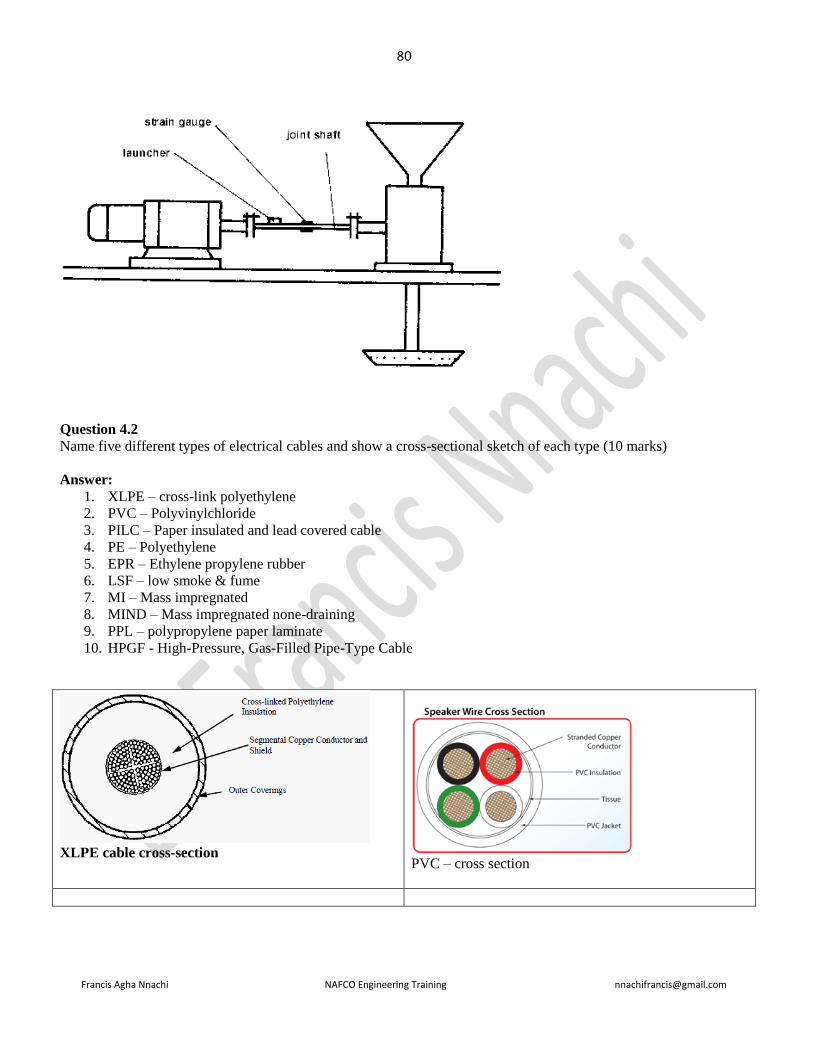
80
Francis Agha Nnachi NAFCO Engineering Training [email protected]
Question 4.2
Name five different types of electrical cables and show a cross-sectional sketch of each type (10 marks)
Answer:
1. XLPE – cross-link polyethylene
2. PVC – Polyvinylchloride
3. PILC – Paper insulated and lead covered cable
4. PE – Polyethylene
5. EPR – Ethylene propylene rubber
6. LSF – low smoke & fume
7. MI – Mass impregnated
8. MIND – Mass impregnated none-draining
9. PPL – polypropylene paper laminate
10. HPGF - High-Pressure, Gas-Filled Pipe-Type Cable
XLPE cable cross-section
PVC – cross section

81
Francis Agha Nnachi NAFCO Engineering Training [email protected]
PILC
HPGF - High-Pressure, Gas-Filled Pipe-Type Cable
Question 5.1
You have decided to inspect all the distribution boards in the plant. Draw up a visual inspection checklist of 20 items
that the artisans must use to ensure that it complies with SANS 10142-1. (10 marks)
Answer:
Check if
1. the DB is correctly rated
2. All protective devices are of correct rating
3. All protective devices are capable of withstanding the prospective fault level
4. Conductors are of correct rating and current carrying acapcity for the protective devices and connected
loads
5. The components have been correctly installed

82
Francis Agha Nnachi NAFCO Engineering Training [email protected]
6. Disconnecting devices are correctly located and all switchgear switches the phase conductors
7. Different circuits are separated electrically
8. Connection of conductors and earthing and bonding are mechanically sound
9. Connection of conductors and earthing and bonding are electrically continuous
10. In the case of the main or first distribution board of an installation, be labelled as "main switch" and sub-
distribution labeled “sub-board..”
11. have a danger notice on or near it
12. Distribution boards shall be protected against corrosion
13. Any point of a distribution board that has to be reached during normal operation shall not exceed a
height of 2,2 m above floor (or walking)level. However, the board may be mounted higher if it can be
disconnected from the supply by a switch-disconnector that is less than 2,2 m above floor level.
14. A distribution board shall not be mounted in a bathroom, above a fixed cooking appliance, within a
radius of 1m from water tap
15. Both ends of the live conductors and of the neutral conductors of a ring circuit shall be crimped together.
Ring circuits shall clearly and permanently be identified by either a notice or a tag.
16. All disconnecting devices in a distribution board shall be protected by a fully rated short-circuit
protective device.
17. Each unoccupied opening of a distribution board shall be fitted with a blanking plate.
18. Unless obvious, permanent labelling shall identify all incoming and outgoing circuits of the distribution
board.
19. The DB shall be suitable for the environmental conditions in which it operates
20. DB shall be so positioned and arranged as to ensure safe operation and maintenance
21. A DB and equipment mounted on it shall be so positioned and arranged that any conductor can easily be
disconnected from the terminals
Question 5.2 (repeated June 2012)
During the shutdown of the plant, you want to test the electrical installation to ensure that the certificates of
compliances are valid. Name 10 tests that you would perform and also the type of instrument that you would use to
verify the results on the test reports. (10 marks)
Answer:
Tests Instruments
1 Continuity of bonding conductors Resistance meter
2 Resistance of earth continuity conductor Resistance meter
3 Continuity of ring circuit (if applicable) Resistance meter
4 Earth loop impedance test at main switch Resistance meter - Loop Impedance &
PSC Tester
5 Elevated voltage on neutral Voltmeter

83
Francis Agha Nnachi NAFCO Engineering Training [email protected]
6 Earth resistance (if required) Earth tester
7 Insulation resistance Insulation tester
8 Voltage (main DB) on no load Voltmeter
9 Voltage (main DB) on load Voltmeter
10 Voltage at available load (worst condition) Voltmeter
11 Operation of earth leakage units Milliameter
12 Operation of earth leakage test button
13 Polarity of points of consumption
14 All switching devices, make and break circuits
Question 7.2
You have seen the following information on a motor data plate. E Ex de IIB T4 Gd, explain the meaning of each
letter that was used on the product as follow:
E Ex de IIB T4 G d
Answer:
E – Conformity with European standard
Ex – indicative of explosion protect (explosion proof)
de – Type of protection, or method of protection, d, e, p, i, o, q, m, n ; level of explosion protection
IIB –Gas group (II - non sparking; B - Explosion group for gases;)
T4 – temperature class or code
G: Gases, vapours or mists;
D: dusts
d: type of protection: flame proof
Question 8.2 (June 2016 Q8.2)
State FIVE benefits by adding water filter head to coolant system (5 marks)
Answer
Adding Water Filter Capability to an Existing Coolant System.
The addition of water filter head and filter can provide significant benefits to the engine, including:
7. Extended water pump life

84
Francis Agha Nnachi NAFCO Engineering Training [email protected]
8. Maximized cavitation corrosion protection
9. Extended coolant life
10. Improved heat transfer
11. Improved thermostat durability
12. Lower cooling system maintenance costs
Question 8.3
Name Three possible signs of debris or contaminant in the coolant coupled with poor to no filtration (3 marks)
Answer
The following coolant related problems are possible signs of debris/contaminant in the coolant coupled with poor to
no filtration:
• Worn rings and scuffed pistons due to poor heat transfer
• Premature water pump failures
• Premature thermostat failures
• Premature radiator failures

85
Francis Agha Nnachi NAFCO Engineering Training [email protected]
===============================================================================
JUNE 2010
==================================================================================
Question 1.1 (repeated Nov. 2011 Q1.1)
State the function of the dual Mobrey level control fitted to a coal fired steam generator (4 marks)
Answer:
Float operated two switch device that performs two functions
1. Switches feed pump on and off to maintain water level in the boiler by varying the opening of a modulating
feed valve
2. Switches on an alarm and a red light on the panel if water level in the boiler drops below normal
Question 1.2 (repeated Nov. 2011 Q1.2)
Describe how to blow down the Mobrey controls (6 marks)
Answer:
Blow down mobrey controls
1. Normal working position
a. The valve handle is kept in the fully turned-out position
b. The steam pipe and float chamber are connected with the water pipe
2. Blowdown of water pipe
a. Turn the valve handle inwards about 2 ½ turns (clockwise). Wait 5 seconds
b. The steam pipe and float chamber are closed off
c. The water pipe is blowing through to the drain
3. Blowdown of steam pipe and float chamber
a. Turn the valve handle inwards fully ( about 5 turns clockwise) wait 5 seconds)
b. The steam pipe and float chamber are blowing through to the drain. The water pipe is closed off
c. Turn the valve fully outwards (anticdlockwise) and close firmly. Check for leakage by feeling
temperature of drainpipe after 15 minutes
Question 1.3 (repeated Nov 2011 Q 1.3)
Name TEN items to be checked or things to be done every 8 hours on a coal fired steam generator (10 marks)
Answer
Check the following:
1. boiler pressure
2. water level in the boiler
3. that the grate is not more than hand-hot and that its color is normal
4. ash build up under stoker via peephole in emergency de-aching door
5. note under grate damper setting
6. ignition of coal through the ignition arch peephole
7. that the coal is flowing correctly in the stoker hopper
8. that the ash trolley is empty. Replace ash trolley and open the ash valve to allow ash to drop into the ash
trolley, then close it
9. the length of the fire through the rear peephole. Adjust under grate damper setting if necessary
10. that the grit trolley is empty

86
Francis Agha Nnachi NAFCO Engineering Training [email protected]
11. that there are enough chemicals in the chemical dosing pump tank for your shift
12. that there is salt in the brine tank of the water softener
13. check the water level in the hot well tank
14. check the log - enter any defect found during handing over immediately
After the first 30 minutes of shift only: blow down both water gauges; blow down both Mobrey controls
Question 2.2
State EIGHT losses in a three-phase induction motor. (4 marks)
Answer
1. Stator cu loss
2. Rotor cu loss
3. Friction loss
4. Stator core loss
5. Rotor core loss
6. Fan loss

87
Francis Agha Nnachi NAFCO Engineering Training [email protected]
7. Magnetic field loss due to air gap
8. Windage loss due to air drag
Question 3.1
The occupational Health and Safety Management systems (OHSAS 18002:2000) – guidelines for the impelemtation
of OHSAS 18001’, is a guideline for the implementation of OHSAS 18001
3.1.1 Name TWO other standards that are well-suited for use with OHSAS 18001 (2 marks)
Answer
1. ISO 9000 series: Quality Management Systems
2. ISO 14000 series: Environmental Management Systems
3.1.2 What are the TWO prime objectives of the OHSAS 18002: 2000 (2 marks)
Answer
In 2000 the BSI produced OHSAS 18002 to provide generic guidance on the application of 18001. This document
describes the intent, typical inputs, processes and typical outputs, against each requirement of 18001 listed above in
order to aid the understanding and implementation of OHSAS 18001.
Question 3.2
A health and safety management system (OHSMS), prescribed by chief inspector, in government notice R859 of 2
September 2005, requires that you must establish an occupational health and safety policy.
Name EIGHT items that management must consider for inputs into the policy
Answer
In developing its OH&S policy, an organization should consider:
1. its mission, vision, core values and beliefs
2. Coordination with other policies (corporate, integrated, etc.),
3. the needs of persons working under the control of the organization,
4. the OH&S hazards of the organization
5. legal and other requirements to which the organization subscribes that relate to its OH&S hazards
6. historical and current OH&S performance by the organization,
7. opportunities and needs for continual improvement and the prevention of injury and ill health,
8. the views of interested parties,
9. What is needed to establish realistic and achievable objectives
Question 3.3

88
Francis Agha Nnachi NAFCO Engineering Training [email protected]
A small induction furnace is used to melt aluminum. Name the hazards associated with such furnaces and give the
precautionary measures to reduce the hazard. (8 marks)
Answer
1. Cold or Easily Fragmented Charge
Cold charge or tools and easily fragmented materials pose a special hazard for induction furnaces and their
operators because they may contain a thin layer of surface or absorbed moisture. On contact with the bath,
the moisture turns to steam, causing spitting or splashing.
Precautionary measures: Appropriate protective equipment and face and eye protection normally will
protect the operator. Preheating the charge and tools prevents many splashing injuries.
In ferrous metal foundries the greatest splashing risk occurs toward the end of the melt, when a foundry worker
adds ferroalloys or introduces tools into the melt. Ferro-alloy materials can absorb moisture from their
surroundings. Sampling spoons and slag rakes collect moisture as a thin film of condensation. Manufacturers’
instructions must be followed for storing alloying materials and preheating tools to minimize moisture
accumulation and reduce the risk of splashing.
In a nonferrous foundry, spitting or splashing can accompany the introduction of ingots into the melt, as surface
condensation comes in contact with molten metal. Ideally, ingots should be placed only in an empty furnace or
on top of solid foundry returns. Ingots added to a molten pool should be preheated or introduced using a remote
charging system.
2. Centrifugally Cast Scrap Rolls
Special steps need to be taken when charging a furnace with centrifugally cast scrap rolls. Ideally, this type of
scrap should not be melted in an induction furnace. The hazard stems from the possibliity that a roll may contain
a ductile inner core surrounded by a brittle outer layer. The different rates of expansion can cause the surface
material to explosively separate from the roll injuring personnel and damaging equipment. Breaking the scrap
rolls can minimize the fragmenting hazard.
3. Wet Charged Material
A wet charge is any piece of scrap metal that contains moisture. Water or moisture present in scrap metal will
instantly be converted to steam upon contact with molten metal. Moisture molecules may expand up to 1,600
times in a single instant. The violence of this reaction causes an explosion capable of launching large amounts of
molten metal into the air. Damage to the furnace can occur, increasing the likelihood of a leak or secondary
explosion. Induction furnaces are cooled by coils of water that wrap around the crucible in which the metal is
melted. This increases the risk associated with adding wet metal to the furnace, as an explosion may rupture
those cooling lines and cause the coolant to leak into the furnace. The coolant hitting the molten metal will create
additional explosions.
4. Sealed Containers
Many foundries melt scrap metal. This process often involves melting metal products back down for repurposing
of the raw metal. Air and gases expand as they are heated. Adding a sealed-off, closed container into a furnace
will cause the air or gas inside the container to expand very rapidly. Should the pressure inside the sealed
container breach the container walls, an explosion will occur. Such an explosion may cause molten metal to be
thrown from the furnace, landing on operators or sensitive equipment.
5. Bridging
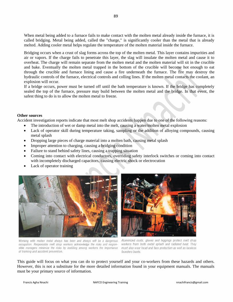
89
Francis Agha Nnachi NAFCO Engineering Training [email protected]
When metal being added to a furnace fails to make contact with the molten metal already inside the furnace, it is
called bridging. Metal being added, called the "charge," is significantly cooler than the metal that is already
melted. Adding cooler metal helps regulate the temperature of the molten material inside the furnace.
Bridging occurs when a crust of slag forms across the top of the molten metal. This layer contains impurities and
air or vapors. If the charge fails to penetrate this layer, the slag will insulate the molten metal and cause it to
overheat. The charge will remain separate from the molten metal and the molten material will sit in the crucible
and bake. Eventually the molten metal trapped in the bottom of the crucible will become hot enough to eat
through the crucible and furnace lining and cause a fire underneath the furnace. The fire may destroy the
hydraulic controls of the furnace, electrical controls and colling lines. If the molten metal contacts the coolant, an
explosion will occur.
If a bridge occurs, power must be turned off until the bath temperature is known. If the bridge has completely
sealed the top of the furnace, pressure may build between the molten metal and the bridge. In that event, the
safest thing to do is to allow the molten metal to freeze.
Other sources
Accident investigation reports indicate that most melt shop accidents happen due to one of the following reasons:
• The introduction of wet or damp metal into the melt, causing a water/molten metal explosion
• Lack of operator skill during temperature taking, sampling or the addition of alloying compounds, causing
metal splash
• Dropping large pieces of charge material into a molten bath, causing metal splash
• Improper attention to charging, causing a bridging condition
• Failure to stand behind safety lines, causing a trapping situation
• Coming into contact with electrical conductors, overriding safety interlock switches or coming into contact
with incompletely discharged capacitors, causing electric shock or electrocution
• Lack of operator training
This guide will focus on what you can do to protect yourself and your co-workers from these hazards and others.
However, this is not a substitute for the more detailed information found in your equipment manuals. The manuals
must be your primary source of information.

90
Francis Agha Nnachi NAFCO Engineering Training [email protected]
Wearing the proper protective equipment can mean the difference between walking away from a melt shop
catastrophe or being injured or killed.
There are two types of protective equipment worn in a melt shop: primary and secondary protective equipment.
Primary Protective Equipment
Primary Protective Equipment is the gear which you wear over your Secondary Protective Equipment when there is
significant exposure to radiant heat, molten metal splash and flame. It is designed to give you the greatest protection.
Primary Protective Equipment should be worn during work activities like charging, sampling, temperature
measuring, slagging, tapping, pouring and casting operations, or whenever there is close proximity to molten metal.
Primary Protective Equipment includes
• Safety glasses,
• a face shield,
• hard hat,
• jacket,
• apron,
• gloves,
• leggings,
• spats,
• cape and sleeves, and
• must be made of aluminized glass fabrics.
For eye/face protection, safety glasses with side shields are the minimum requirement. For molten metal exposure, a
face shield is needed in addition to safety glasses. Your eyes are extremely susceptible to injury, and protection is so
easy to provide. For head protection from flying/falling objects, shocks, splashes, etc., a hard hat must be worn.

91
Francis Agha Nnachi NAFCO Engineering Training [email protected]
Working near places where there is heat, heat resistant/flame retardant gloves should be worn. In working near
molten metal, melt shop gloves which extend above the wrists must be worn.
For protection of the body, arms and legs, aluminized glass outerwear has been recommended by the American
Foundry Society (AFS) for protection against radiant heat and molten metal splash.
Laceless safety boots are required for foot protection from molten substance exposure. They can be removed quickly
in case metal gets inside. Metatarsal-guard shoes protect the top of the foot. If laced boots are worn, they must be
covered with spats, especially near the top where there is danger of the molten metal entering.
Secondary Protective Equipment
Along with Primary Protective Equipment, as dictated by the working environment; e.g. safety glasses, hard hat, ear
plugs, hard toe boots, etc., Secondary Protective Equipment is worn in areas where there is less hazard and is used to
prevent ordinary clothing from igniting and burning. Flame resistant coveralls would be an example of Secondary
Protective Equipment. Secondary Protective Equipment will help to reduce burns significantly
In many cases, serious burns and fatalities have occurred because ordinary clothing caught fire from a small spark or
splash, not because of burns caused directly by molten metal. Along with Secondary Protective Equipment you also
must wear natural fiber outer clothing, undergarments and socks. Some synthetic fabrics melt or catch fire and this
can increase the burn hazard. AFS recommends the use of washable, fire resistant undergarments. Certainly, melt
shops are hot places to work and Personal Protective Equipment (PPE) adds to the problem of heat-related stress, but
it can save your life.
-----------------------------------------------------------------------------------------------
Lower Temperature, Higher Risk of Metal Splash
While some metals melt at a lower temperature than ferrous metals, they, in some respects, present a greater metal
splash hazard to the melt shop worker. Low temperature metals and their alloys, such as aluminum, galvalume, tin,
lead, galfan, zinc, copper and copper alloys, etc., stick to bare skin, producing severe and possibly disfiguring burns.
If larger amounts of metal are involved, the burns can be fatal. Wearing Personal Protective Equipment (PPE),
including safety glasses, face shield, head and body protection, and foot and hand protection is crucial to safety when
working in proximity to molten metals, regardless of the melting temperature.
Masks & Respirators
Where airborne hazards and noise pollution pose a threat, safety professionals also specify the use of respirators and
hearing protection devices. Silica dust particles are considered a health hazard when inhaled over time.
Inhalation without protection may cause severe irritation of the respiratory system, leading to silicosis or cancer.
Please refer to the manufacturer’s warning

92
Francis Agha Nnachi NAFCO Engineering Training [email protected]
Question 4.2
The pipes used for transporting fluidized coal, from the crushing plant to the boiler, needs to be lined with ceramic.
State FIVE advantages and FIVE limitations for using ceramic (10 marks)
Answer
Advantages
1. High strength at elevated temperatures.
2. High modulus of elasticity.
3. Low density.
4. Dimensional stability.
5. Resistant to corrosion.
6. Resistant to abrasion.
7. Resistant to creep.
8. Thermal properties can be adapted.
9. Electrical properties can be adapted.
10. Easily formed into shapes.
Limitations
1. Brittle materials unless expensive toughening procedures are used.
2. Very low impact strength (no ductility).
3. Non-oxide ceramics oxidise at high temperatures.
4. Low thermal conductivity ceramics have poor thermal shock resistance.
5. Green machining after forming is done but it is not precise
6. Final sizing is via grinding using diamond or cubic boron nitride.
7. Turning is not an option once sintered.
8. There are size limitations to engineering ceramics. These are often related to the size of the forming
equipment available. Most of the forming equipment is extremely expensive.
9. Good surface finishes are only possible by diamond polishing or lapping.
10. Drilling holes, machining threads and sharp changes in section generate stresses and subsequent
cracking, however newer methods have been developed where holes and slots etc. can be machined into the
sintered material. Sonic grinding is finding more widespread use and features can now be incorporated into
the finished ceramic without stressing and subsequent cracking.
93
Francis Agha Nnachi NAFCO Engineering Training [email protected]
Question 5.1 (repeated in June 2014 Q 4.1)
State FOUR safety considerations to determine the nominal cross-sectional area of a conductor in an electrical
installation. (4 marks)
Answer
SANS10142-1: 5.2.3 (page 72)
The nominal cross-sectional area of a conductor shall be determined in accordance with the following safety
considerations:
1. The conductor's maximum permissible continuous temperature;
2. The permissible voltage drop of an installation;
3. The electromechanical stresses and thermal effects that is likely to occur as a result of short circuits;
4. The maximum impedance of the conductor with respect to the functioning of the short-circuit protection; and
5. Mechanical stresses.
The required size of conductor is determined by
1. Current carrying capacity of the cable
2. Permitted voltage drop
3. Requirement for overcurrent protection & short-time overcurrent rating
Question 5.2
Where may flexible cords be used in an electrical installation? (4 marks)
Answer
Flexible cords shall not be used as part of the electrical installation, except where
a) Required by the relevant product solely for termination or connection of moving parts,
b) Specified in the product standard,
c) used as single cores in conduits,
d) Used in an authorized wiring system, or
e) needed for the connection of luminaires, provided that each connection is limited to one luminaire and to a
maximum length of 3 m.
Question 5.3
What information must be on a multicore extruder dielectric insulated cable? (3 marks)
Answer:
1. Manufacturer’s name;
2. trade name or trade mark;
3. Operating voltage;
4. Identification of special properties
Question 5.4
State TWO requirements for the marking of multicore extruded solid dielectric insulated cables ( 2 marks)
Answer
94
Francis Agha Nnachi NAFCO Engineering Training [email protected]
Question 5.5 (Repeated in June 2014 Q 4.5)
State SEVEN requirements for outdoor storage of cable drums (7 marks)
Answer
• Drums should be stored on a hard surface at a slight angle and the area should have a drainage system
• Drums should be released on a “first in first out” basis
• Cable ends should be sealed at all times
• Stack flange-to-flange but if this is not possible limit vertical stacking practice to smaller drums only
• Stack in such a way that drums are easily accessible
• Observe fire protection rules
• Cable racks are ideal for storage but take care not to overload
• Cables must be identifiable at all times
• If drums are expected to be stored for a long time they must be specially treated or made of hard wood
• Rotate paper insulated cable drums one complete rev per annum.
Question 6.2 (repeated Nov. 2006 Q4.1)
Name FOUR items to check on a steel wire rope, used on a gantry crane, when carrying out a periodic inspection.
Discuss each item (8 marks)
Answer
10. Broken wires: A wire rope must be discarded if the permissible number of wire breaks is reached or
exceeded. It must also be replaced when local concentrations of wire breaks occur.
11. Reduction in diameter: reduction in diameter can be caused by abrasion, corrosion or a local failure of the
rope core.
12. Corrosion: corrosion may be external or internal, general or localized. A wire should be discarded when the
surface of the wires is severely roughened or pitted, or if the wires are slack within the strands due to
wastage.
13. Rope deformation: (a) Waviness: this deformation, while it may not necessarily affect the strength of the
rope, can transmit pulsation and produce uneven rope wear.( b). Birdcage (basket deformation): A birdcage
develops when the outer layer of strands becomes longer than the inner layer or layers. The condition may
occur as a result of incorrect fitting, tight sheaves, shock loading, incorrect use of a swivel or the application
of a heavy load to a new rope before the strands have settled into position. Ropes with a birdcage should be
discarded. (c). Loop Formation: wires or groups of wires may form a line of loops parallel to the axis of the
rope. This deformation is often caused by shock-loading. Loop formations are justification for discard.(d)
Nodes, (e) thining of the ropes, (f) misplaced outer wires, (g) kinks, (h) flat areas
14. Damage caused by heat
Question 7.2
Give TWO major reasons why will use aluminium, instead of copper, for busbars in a power transmission substation.
(2 marks)

95
Francis Agha Nnachi NAFCO Engineering Training [email protected]
Answer
Key benefits of aluminium for use in busbar systems
• Cost: On the world’s commodity market, aluminium tends to have a more stable value and, unlike copper, is not so
sensitive to the ‘ebb and flow’ of consumer demand, political uncertainties and other economic factors. As a result,
aluminium has consistently provided huge cost savings for specifiers and contractors.
• Weight: Aluminium is up to 70 per cent lighter than copper. This not only saves money on transportation, but also
on the time, effort, and therefore cost, of installation.
• Conductivity: In general the conductivity of copper is significantly better than aluminium (aluminium’s
conductivity is 62 per cent that of copper). However, the weight of copper is three times that of aluminium, which -
as previously stated - has a significant impact on the cost of installation and transportation. When you compare an
aluminium system against a copper-based system of equal size and weight, aluminium scores twice as conductive as
copper.
• Jointing: In the past, specifiers have been critical of the fact that aluminium is susceptible to oxidisation, which
affects the contact conductivity at the joint. Manufacturers of busbar systems have overcome this factor by
completely electro-tin plating the conductor bars, which eliminates any problems associated with jointing dissimilar
metals.
• Safety: Unlike ferrous metals, aluminium does not generate sparks when used in combination with other metals,
making it the ideal choice for use in potentially inflammable or explosive environments.
• Non-magnetic: As aluminium is nonmagnetic it is ideal for use in applications that need minimum magnetic
interference. These include high-voltage applications as well as electronics.
• Mechanical strength: Aluminium alloys have a mechanical resistance of 60 to 530 Newton/mm². This is more
than sufficient.
Corona is less in Aluminium than in copper Its relatively large diameter for a given conductivity reduces corona.
Corona is the discharge of electricity from the wire when it has a high potential. The discharge is greater when
smaller diameter wire is used than when larger diameter wire is used
Key benefits of using aluminium instead of copper windings for cast resin transformers:
• The coefficient of thermal expansion of aluminium is more similar to the coefficient of the resin than coppers.
When the transformer is loaded the ideal compatibility between the expansion coefficient of aluminium and of the
resin used for casting prevents the creation of cracks in the cast resin coils.
• Since aluminium windings work at a lower current density than copper windings this characteristic enables them to
have a better short term overload capacity.
• Aluminium wound cast resin transformers are lighter in weight than the copper wound ones due to the difference in
the specific weight of the two materials.
• Aluminium wound transformers compared with equivalent copper wound ones guarantee the same efficiency.
Question (repeated Nov 2011 Q4.3)
Name THREE major welding methods to weld aluminum alloys. (3 marks)
Answer
1. MIG (Metal Inert Gas) welding also called GMAN (Gas Metal Arc welding)
2. TIG (Tungsten Inert Gas) welding

96
Francis Agha Nnachi NAFCO Engineering Training [email protected]
3. Arc Welding
Question 8.2
Name FOUR basic steps that are performed at crude oil refineries
Answer
1. Distillation
2. Cracking
3. Treating and
4. Reforming
Question 8.3
SANS 484-1 and SANS 484-2 gives two methods to joint conventional splicing of textile-reinforced multiply rubber
covered conveyor belting, namely hot-splicing method and cold-splicing method. Give a description of the TWO
methods
Answer
SITE SPLICING
PRELIMINARY INFORMATION REQUIRED
Before commencing any field splicing operation the following points should be carefully checked, preferably by a
visit to site :
1. Ensure that there is sufficient belting in the system to enable a splice to be made.
2. Select a suitable point on the conveyor system for making the splice, having regard to :
a) Ease of operation, including the handling of heavy a press.
b) Necessary cover if the installation is open to the weather, so that the operation can be carried out in dry
conditions.
c) Ability to tension the belt conveniently, ie. suitable anchorage points available for the clamps and wire
lashings used for tensioning with pull-lifts or winches.
3 . Check that a satisfactory power supply for the vulcanising press is available where required.

97
Francis Agha Nnachi NAFCO Engineering Training [email protected]
4. Obtain full details of the type, size and cover grade of the belt to be spliced so that the correct splicing
materials can be used.
5. In the case of used belts, ensure that the condition of the belt is good enough to warrant splicing, Good
splices are impossible in a belt \vhich is badly damaged or wet, etc.
EQUIPMENT AND MATERIALS REQUIRED
Vulcanising and setting-up equipment
1. Vulcanising press which should have platens at least lOOmm \vider than the belt to be spliced.
2. Set of press irons of sufficient length to allow clamping outside the ends of the patens. Thickness to be
approximately 10% less than that of belt to be spliced.
3. Two steel plates wide enough to cover width of belt and press irons, and longer than press platens.
4. Work boards made of heavy gauge playwood or blackboard.
5. Two joiner's clamps.
6. Three belt clamps.
7. Two pull lifts (one each side of belt).
Splicing tools
Steel straight edge, steel T-square, steel tape, two hand rollers, edge wheel, screw driver, pincers, prickers,
scissors, spew trimmer, hand knife, one-ply knife, V-knife, ply cutters, wire brush, hand brush, solvent pads,
emery paper, marking pencil, spanners to fit vulcanising press, two pairs of gloves.
Splicing materials
1. Calendered carcass skin gum batched in cellophane.
2. Lena breaker reinforcement - ready topped with rubber.
3. Cover splicing gum of suitable thickness.
4. Solution.
5. Solvent in suitable container.
Setting up the belt
When the belt has been positioned on the conveyor structure it must be tensioned by the use of clamps before the
splice is made, in order to reduce the stretch in the belt after the splice has been completed and the clamps have
been removed.
A suitable clamp is fixed to each belt end and the tension is applied through the clamps by means of pull-lifts or
suitable tensioning devices. Stretch is then taken out of the belt by drawing the two clamps together, tl1e prepared
ends of the belt being slack between the clamps.
Alternatively, one of the clamps can also be fastened securely to the structure, tension then being applied between
a point on the structure and the other clamp. With this method, however, it is necessary to use more tension than
with the method where the two clamps are drawn together.
98
Francis Agha Nnachi NAFCO Engineering Training [email protected]
Similarly, slope belts which are spliced at the top of the slope require more tension during splicing than those
spliced at the bottom.
When a belt system is fitted with a moving gravity weight take-up, it is necessary to apply the tension and lift the
weight until it has reached the position where it is expected to float when the belt is running empty. This operation
should preferably be performed by clamping to the structure the end of the belt nearest to the gravity weight and by
pulling the other end so that the pull is transmitted right round the system and into the gravity take-up position. All
pulleys must be free to rotate during this tensioning operation.
When the belt system is fitted with a fixed take-up device, the pulley must be moved into the 'off position' so that
the belt is at its shortest length when spliced.
It is often convenient to place the bottom platen of the vulcanising press in place at the start of the operation and to
assemble the splice on top of it. The top platen can then be placed over it and the splice vulcanised when the latter
has been completed.
Before preparation of the splice is started, the belt should be checked to ensure that the face cover is uppermost on
the carrying side.
General information of splicing
Two different types of splice are used for XT belts. Two ply constructions are spliced by the jump-type splice,
whilst for belts of three plies or more the stepped bias splice is used.
In all cases the belt ends to be joined together are prepared in a series of steps. The number of steps is one less than
the number of plies for belts of three plies or more, whilst a special double step is used for two ply belts. The
length of the steps to be used in the splices is dependent upon the strength of the individual plies in the belt.
Presume that the belt is to run on idlers, in which case the splice should be prepared and assembled so that the
cover gum fill-in on the back cover leads that on the face cover. If the belt is to run over slider plates instead of
idlers, the direction of running should be reversed so that the tip of the splice cannot be caught on the slider plates.
Stripping down the belt ends for splicing
1. First mark out the centre line of the belt by measuring the mid point of the belt width at a number of stations
and joining these together. This centre line must now be used as a datum for all other measurements; the
belt edge should not be used as a reference.
2. Now mark off a base line at right angles to the belt centre line datum to denote the inward limit of the
splice. In order to allow for subsequent trimming of the outward end of the splice, the base line should be
drawn at a distance from the belt end greater than the total splice length. The trailing end of the belt will
have the base line marked on the back cover and the leading end of the belt on the face cover.
3. Mark off the bias length along the belt edge from one edge of the base line. Join the marked point to the
other end of the base line to give the splice line. Mark off a line parallel to this, inward of it and strip off the
cover rubber between the lines. With a marking pencil, re-mark the splice line on the outer ply and remove
another strip of cover rubber outward of the splice line. This will ensure that the splice line is still visible
when the two strips of cover rubber have been removed. It is necessary to remove the second strip to enable
the single ply cutting knife to be used.

99
Francis Agha Nnachi NAFCO Engineering Training [email protected]
4. Cut through the first ply along the splice line using a single ply knife. Great care should be taken not to cut
deeper than intended or to cut into or destroy any fabric which is to remain a part of the splice.
5. Remove the first ply and cover rubber in strips outwards of the splice line. Pre-\varming of the splice area
is recommended to facilitate stripping,
6. Mark off bias plus step length along belt edge from the base line and draw step line. Cut second ply with
single ply knife, again taking great care not to cut deeper than intended.
7. Mark the other steps from the base line and prepare in the same way.
8. Cut through the last ply and cover rubber at the lend of the splice to make the last step longer than the
normal step length.
9. Remove cover rubber for a strip on the reverse side of the belt,
10. Repeat the stripping down operations for the reverse side of the belt on the second end commencing by
marking the bias length along the belt edge from the base line and joining the marked points.
NOTE :
In preparing the steps of the splice, measurements are taken from the base line across the belt. The edge of each
step must be measured from this line and not from the edge of the previous step,
Cleaning and rubbering of splice:
1. Take off any surplus rubber or fabric from the ply step with a wire brush, taking care not to damage the
fabric.
2. Buff the rubber cover adjacent to the splice to ensure satisfactory bonding. Never apply adhesive to any
fabric surfaces unless they have been thoroughly buffed and cleaned, Dirty surfaces will not vulcanise or adhere
properly.
3. Paint the steps at each end of the belt with two coats of XT solution, ensuring the each coat·is dry before
proceeding with the next operation.
4. Apply a layer of calendered carcase skin gum to the steps of the leading end of the belt and roll well down.
In he case of the jump type splice on 2 ply belts, several layers of skin gum should be used to build up the
centre part of the splice.
5. Lay out the belt end prepared \-lith skin gum and fit the other end to it. When matching the two ends
together it is advisable to leave the protective backing supplied with the carcase skin gum in place so that
the surfaces do not adhere. Make sure that the splice is properly aligned and that the fabric steps do not
overlap at any point, It is equally important not to leave gaps between the steps. It is also important to check
that there is no twist in the belt.
6. When the splice is perfectly matched, turn back one half and remove half the backing, then roll down that
half of the splice before removing the mating up the other half.
7. Dig in and trim off the overlapping end of the last ply on the face and back to make a close fitting joint.

100
Francis Agha Nnachi NAFCO Engineering Training [email protected]
8. Apply solution to edges of rubber along channel in covers. Insert strip of carcass skin gum followed by lena
breaker of the requisite width along the channel. Apply a further coat of solution and then fill in with cover
splicing gum of the appropriate gauge.
9. Roll and thoroughly prick the whole splice area.
10. Remove working surfaces from conveyor and place vulcanising press into position.
Vulcanisation
1. It may be necessary due to the length of the splice to have to cure the splice in more than one charge. Make
sure on the first and last charge that the ends of the splice are inside the platens of the vulcaniser, and that an
adequate overlap exists between subsequent charges.
2. Position side irons.
3. Position top section of press but do not finally close.
4. Key up the side irons using sash clamps.
5. Finally close press and set to required pressure and temperature.
6. After curing the splice, remove the vulcanising press, trim of excess spew and examine.
Vulcanising pressure
The vulcaniser should be set according to the marker's instructions and the type of machine, so as to give a
minimum curing pressure between press platen and belt surface.
==================================================================================
November 2009
==================================================================================
QUESTION 1.1 (repeated June 2012 Q1.1)
In view of increasing fuel prices, it has become of prime importance to economise on the use of fuel and to practice
energy conservation. You are responsible for the boiler plant consisting of three horizontal fire-tube boilers of which

101
Francis Agha Nnachi NAFCO Engineering Training [email protected]
any two are generally on line to meet a load of 15 t/h. the plant runs 24 hrs/day, 7 days per week and is provided with
good instrumentation.
Assuming that the unburnt losses are minimized and that the boiler feedwater is supplied from a de-aerator at 105oC
and that the boiler exit flue gas temperature is 250oC, answer the following questions:
1.1.1 What is the biggest single loss factor affecting the steam generator efficiency (1 mark)
1.1.2 How would you improve the steam generator efficiency by about 4% from 76% to 80% in the case of a coal-
fired generator? (13 marks)
Answer
(a)
The question does not indicate if the boilers are equipped with economisers or combustion air heaters. It does,
however, specify that the boilers are fire-tube type. In package form these boilers are generally, not supplied with
either economisers or combustion air heaters. Consequently this solution approaches the problem from that angle.
There are numerous, unavoidable ways in which boilers on range loose heat. Radiation through the shell and gas
passage covers is reduced by lagging, but is nevertheless present. Every time boiler water is dumped during the
essential, twice or thrice daily blowdown periods hot boiler water is discharged. Be that as it may, the major loss of
more or less usable heat is in the hot flue gas, which is exhausted after passing through the two or three heat transfer
passages (passes) in the boiler.
In oil and gas fired boilers combustion air masses can be controlled to a high degree of accuracy and precision. This
means that the mass of flue gas is kept to a practicable minimum and thus the quantity of heat energy contained in
the flue gas, for a given temperature, is minimised. Thus losses are kept to a minimum, as far as mass of flue gas is
concerned. In coal fired boilers there has to be an excess of combustion air, as the combustion of coal is a two stage
process; 2C + O2 2CO and then, with excess (secondary) air, 2CO + O2 2CO2. More air than the stoichlometric
mass will have to be supplied to ensure complete combustion and there will thus be a greater mass of flue gas than
the theoretical ideal. As a consequence of this more heat energy exists in the flue gas of a coal fired boiler (for an
equal gas temperature) than will be lost from an equivalent oil or gas fired boiler.
Obviously, it is this supply of heat in the flue gas which has to be the target in endeavours to improve boiler
efficiency. The proven methods of achieving this are the aforementioned economiser and combustion air heater (also
known as a pre-heater). Tube passes are arranged in the flue gas, after it exists the last set of gas passeges in the
boiler. Feedwater pumped through these passes, prior to entry to the water space of the boiler, which is effectively an
evaporator, extracts heat energy from the flue gas and in so doing the enthalpy of the water is increased (and the
temperature of the flue gas reduced). This means that more of the heat energy applied to the boiler water, in the
evaporator, can be used to provide latent heat of evaporations, i.e. produce more steam.
A heat exchanger is situated in the flue gas, down stream of the economiser and the combustion air is blown through
it, by the forced draught (FD) on the way to the furnace. This air extracts heat energy from the flue gas. This means
that heat energy released in the combustion of the fuel can raise the temperature of the products of combustion above
that reached with unheated combustion air. The effect of this is to compensate for the temperature rise in the water
102
Francis Agha Nnachi NAFCO Engineering Training [email protected]
entering the evaporator, as a result of the economiser effect, and drive more heat into the boiler water, per kg of flue
gas. (heat transfer is a function of a temperature differential – the greater the differential, the greater the heat transfer.
The economiser is situated before the air heater for reasons of temperature differentials, which are essential to the
flow of heat energy. Feed water, which is normally hot (although not as that quoted in the question, as at 105 oC the
dearator has to be pressurized, which is an inordinary stupid thing to do, because if the object is to get gases out of
solution, the pressure in the dearator must be reduced), say 80 oC, is passed through the flue gas which is at say 250
oC, to experience an initial temperature differential of some 130 oC. Combustion air, at perhaps 25 oC, is passed
through the flue gas, down stream of the economiser, where the flue gas temperature is say 220 oC, to be exposed to
an initial temperature differential of some 195 oC.
At the end of the day, some but by no means all, of the heat in the flue gas is recovered, placed ibto the steam and
made available for use. The fact that not all the heat is recovered is a result of the relatively low temperature of the
flue gas, after passing through the quoted recovery devices. The remaining temperature differential is too small to be
used in a practicable manner.
(b)
For the purpose of illustration a 7.5 ton per hour, fire tube, “John Thompson” type of boiler has been considered. The
operating pressure is 950 kPa. A dryness fraction of 0.98 is used. Reference to steam tables indicates a working
temperature of 182 oC (1050 kPa abs). The mass flow of the steam per second, 𝑠 = 2.0833 𝑘𝑔/𝑠. Fuel consumed
per second, 𝑓 = 0.25 𝑘𝑔/𝑠 (approximately) of coal with a calorific value of 25.2 Mj/kg. For a fuel to combustion
air ratio of 1:20 tha mass of air required per second, 𝑎 = (20 𝑥 0, 25) = 5 𝑘𝑔. The mass of flue gas generated per
second, for the production of 2.08 kg/s of steam, 𝑔 = (0.25 + 5) = 5.25 𝑘𝑔/𝑠. A workable value for the specific
heat of flue gas is 𝐶𝑝 = 1.086𝑘𝐽/𝑘𝑔𝑘
If the boiler efficiency is to be 80%, a heat balance check shows that to generate 2,0833 kg of 98 % dry steam, from
feed water, from 5987.5 kJ of heat supplied in the fuel. This means 2376 kg of fuel and 4.75 kg of air.
Installation of a purpose built economiser, in the flue where the gas tempersture is 250 oC, for an efficiency of 80%,
could extract sufficient heat from the gas to reduce its tempersture say 241 oC. The heat balance here is
∆𝑇𝑔. 𝑔. 𝐶𝑝 = ∆𝑇𝑤𝑤𝐶𝑤
Where the subscript w is for feed water. 𝑤 = 𝑠
Therefore, (250 − 241) × 4.9896 × 1.086 = (𝑇𝑤 − 105) × 2.0833 × 4.186
𝑇𝑤 =9 × 4.9896 × 1.086
2.0833 × 4.186+ 105 = 110.6 𝑜𝐶
The air heater is situated in the flue gas where the gas temperature is 241 oC. A viable temperature for the
combustion air, after the pre-heater, is 60 oC. Ambient air temperature is taken as 20 oC. For this exercise the heat
balance is

103
Francis Agha Nnachi NAFCO Engineering Training [email protected]
∆𝑇𝑎 . . 𝐶𝑎 = ∆𝑇𝑔𝑔𝐶𝑔
Therefore, (60 − 20) × 4.9896 × 1.005 = (241 − 𝑇𝑔) × 4.9896 × 1.086
Therefore,
37 = 241 − 𝑇𝑔 ;
𝑇𝑔 = 204 𝑜𝐶
Heat energy content of the flue gas is 4.9896 × 204 × 1.086 = 1105.4 𝑘𝐽
The heat transferred by and entrained in the component parts of the boiler is shown on the accompanying sketches. In
the first instance the boiler is shown only an evaporator and the heat balance devolves to an efficiency of 76 %. In
the second instance the effects of both an economiser and a preheater are shown, with a resultant efficiency of 80 %.
As stated earlier, the temperature of the gas exiting the furnace is a number of degrees higher with an air heater tha
without it. Thus the heat energy transferred to the boiler water in the evaporator, per kg of flue gas, is increased. In
fact the increase in gas temperatue is given by
∆𝑇 =4.75×1.005×(60−20)
4.9896×1.086= 35.25 𝑜𝐶 higher at exit from the furnace than the temperature when no air heater is used.
Diagram……..
Question 2.2 (repeated June 2007 Q 7.3)
Discuss the common mistakes made that cause wastage of electrical energy in electrical motors.(6 marks)
Answer
• Operating electric motors under less than full load: Induction motors have distinct inefficiencies in that
they cannot effectively adjust the amount of electricity they consume for the work they do. When they
operate under less than full load, substantial power is wasted – a soft starter could be a consideration
• Operating electric motor without a power factor correction: A power factor less than unity results in the
following disadvantages:- Large kVA rating of equipment, greater conductor size, large copper losses, poor
voltage regulation, reduced capacity handling of the system
• Evaluating electric motor usage by load and not including operating hours: Two of the most important
concerns in evaluating energy usage are actual load and operating hours
• Not oversizing of electric motor to ensure load capability results

104
Francis Agha Nnachi NAFCO Engineering Training [email protected]
QUESTION 3.1
A control building needs to be designed to accommodate a distribution board, traffic control equipment for the
booms and traffic lights, computers uninterrupted power supply, et cetera.
Name FOUR measurements that should be considered to prevent a fire or explosion and discuss the reasons for these
measurements. (8 marks)
Answer
QUESTION 3.2
A health and safety management system (OHSMS) as prescribed by chief inspector in government notice R.859 of 2
September 2005 requires that you must be prepared in the case of an emergency.
Name SIX examples of emergency equipment that shall be considered. (6 marks)
Answer
Emergency equipment
Emergency equipment needs should be identified, and equipment should be provided in adequate quatity. This
should be tested at specified intervals for continuity operability.
Examples include the following items:
1. Alarm system
2. Emergency lighting and power
3. Means of escape
4. Safe refuges
5. Critical isolation valves, switches and cut-outs
6. Fire-fighting equipment
7. First aid equipment (including emergency showers, eye wash stations, etc)
8. Communication facilities
Question
Discuss the position of socket outlets in electrical installation.
Answer

105
Francis Agha Nnachi NAFCO Engineering Training [email protected]
A socket-outlet that is exposed to the weather (or to the condensation, dripping, splashing or accumulation of water)
shall have a rating of at least IP44 in accordance with SANS 60529/IEC 60529 (SABS IEC 60529). The rating
applies whether a plug is in or out.
A floor-mounted socket-outlet (recessed or not) shall be so mounted that
a) the floor can be cleaned or washed without the insulation resistance of the installation being affected, and
b) there is no risk of live parts touching any floor covering used.
3. A socket-outlet shall not be installed within a radius of 2 m of a water tap (in the same room)
unless the socket-outlet
a) has earth leakage protection, or
b) is connected to a safety supply.
Question
Give SIX requirements for a fireman’s switch in an electrical installation.
Answer
A fireman's switch shall
a) Be in a red-coloured enclosure,
b) Be switched off when the lever is at the top,
c) Have the closed and open positions marked with lettering that can be clearly seen by a person (who has normal
eyesight) standing on the ground,
d) Be fixed in a clearly visible position that can easily be reached by firemen,
e) Unless otherwise permitted by a fire officer, be about 2,75 m above ground level,
f) For interior signs, be at the main entrance of the building or structure or in another position acceptable to the fire
officer,
g) in the case of an exterior sign, be next to the sign (but, if the switch controls more than one sign, the switch shall
be next to one of the signs and there shall be a notice under each of the other signs to show where the fireman's
switch can be found. Another arrangement may be used if acceptable to the fire officer), and
h) If there is more than one switch in a building or structure, be marked to indicate which sign(s) (or part of the
building) it controls.
Question

106
Francis Agha Nnachi NAFCO Engineering Training [email protected]
Give THREE requirements for cables for circuits that operate at voltage exceeding 1000V.
Answer
SANS 10142:2008 Page 265
7.13.11.2 Cables for circuits that operate at voltages exceeding 1000 V shall
1. not be run in the same channel of wireway as the cables for circuit operate at a voltage of less than 1000 V .
2. be identifiable at their terminations and
3. be fixed at appropriate spacing given in table 7.5
Question
Name FOUR powering methods of turbines and give the most common problem in each method.
Answer
1. Steam powered turbine: pollutes the atmosphere due to production of large amount of smoke and fumes
2. Hydro powered turbine: involves high capital cost due to construction of dam; uncertainty about the
availability of huge amount of water due to dependence on weather conditions
3. Diesel powered turbine: high running charges as the fuels (i.e. diesel ) used is costly.
4. Gas powered turbine: there is a problem of starting the unit. It is because before starting the turbine, the
compressor has to be operated for which power is required from external source. Since a greater part of
power developed by the turbine is used in driving the compressor, the net output is low.
5. Nuclear powered turbine: fuel used is expensive and is difficult to recover. The capital cost on a nuclear
plant is very high as compared to other types of plants
Question

107
Francis Agha Nnachi NAFCO Engineering Training [email protected]
Explain THREE methods of how to locate a fault in a buried 3-core PVC shearted PILC SWA cable.
Answer
Measure resistance of faulty core to shorted armouring/earth conductor/ second core with low range resistance meter.
Repeat procedure with sound core, bridged to the same element at a known distance. Calculate he fault point by
using the two different resistances and know the distance.
Apply a high voltage impulse generator to the end of the cable and listen to the sound associated “thumping” noise
along the route of the cable by means of directional earphones. The ‘thumping’ sound is loudest at the fault.
Connect an echo impulse generator to the one end of the cable. Enter the correct impedance characteristic. Ensure
that an identified landmark of known distance from the impulse generator is located on the screen. The fault distance
is calculated between the impulse generator and the known landmark.
Murray test loop test.

108
Francis Agha Nnachi NAFCO Engineering Training [email protected]
=================================================================================
June 2009
=================================================================================
========================================================================
QUESTION 1.1
A statutory inspection needs to be carried out on a three pass economic type welded horizontal boiler. Name 20 items
to be checked
Answer
1. Identify boiler as on copper plate or data plate and its plate and its Registration Certificate. Note its AWGP.
2. Use low-voltage (max. 50 W) hand lamps and/or torches. Burners or coal grates to be removed. Make boiler fully
accessible (internal and external) and ventilated.
External:
3. Inspect shell for rust and wastage. Remove cladding where corrosion is suspected. Inspect all welded seams and
flanges.
4. Inspect circumferential and longitudinal seams of flue. Check roundness of flue and front and rear welded seams
and general wastage.
5. Check front and rear tube plates, tube expansions and note signs of leakage. Check all ligaments for cracks.
6. Inspect inner tube plate and tube expansions. Look for cracks in welding where tubes are welded into the tube
plate. Check for cracks in the ligaments.
7. While in the combustion chamber check plating for distortion and the welding of the stay bar ends. Look for
blockages in the stay bar holes in the ends of the stay bars.
8. Inspect all tubes for straightness and possible blockages. Also any deposits are removed.
9. Check all tube plates with a straight edge for possible deformation (bulching).
Internal:
10. Check scale or corrosion on tubes and tube plates. Collect samples of scale (loose or attached) for analysis.
11. Check securing of steam/water separator box.
12. Check for blocked holes in the internal feed maker pipe and its securing.

109
Francis Agha Nnachi NAFCO Engineering Training [email protected]
Appurtenances:
13. All valves and other fittings must be overhauled and opened up for inspection. Pressure gauges to be checked and
verified.
14. Examine all mountings, studs and bolts for soundness.
15. Blowdown cock, line and pit to be examined as one entity. Pit cover bolted on with 2 m standpipe. Ensure line is
free and above any water in trench.
Controls:
16. Check that electrical controls are fitted in water proof and locked box.
17. Control panel and indicators to be in compliance.
18. Wiring put in metal tubing and secured at both ends.
19. Drive belts for fans (FD and ID) to be checked for cracks or wear.
20. Feed pump (s) performance to be monitored by user and entered in log book.
General:
21. Request user to have stay wires of chimney stack examined and recorded in log book.
22. Request user to repair roof and/or take steps where rain water runs down the chimney onto the boiler.
QUESTION 3.1 (repeated Nov. 2011 Q3.1)
A special steel container 6 m (length) x 2.4 (width) x 2.6 m (height) needs to be placed inside a sump that is 6 m
deep and close to an overhead power line. A risk assessment needs to be carried out. Name the risks involved and
precautionary measure to be taken to place the container safely into the sump. (8 marks)
Answer
QUESTION 3.2 (Repeated Nov 2006 Q3.3)
The employer must establish an occupational health and safety management system (OHSMS)
3.2.1 State SIX items or documents to be considered for the planning stage (OHSMS) (6 marks)
3.2.2 Discuss the implementation and operation elements of the OHSMS (6 marks)
Answer

110
Francis Agha Nnachi NAFCO Engineering Training [email protected]
3.2.1
• Hazard identification, risk assessment and determining controls
• Legal and other OH&S requirements
• Competence, training and awareness
• Communication, participation and consultation
• Control of documents
• Operational control
• Emergency preparedness & response
• Performance measurement and monitoring
• Evaluation of compliance
• Incident investigation, nonconformity, corrective & preventive action
• Control of records
• Internal audit
3.2.2
Resources, roles, responsibility, accountability and authority
Top management shall demonstrate its commitment by:
a) Ensuring the availability of resources essential to establish, implement, maintain and improve the OH&S
management system;
NOTE 1 Resources include human resources and specialized skills, organizational infrastructure, technology and
financial resources.
b) Defining roles, allocating responsibilities and accountabilities, and delegating authorities, to facilitate effective
OH&S management; roles, responsibilities, accountabilities, and authorities shall be documented and communicated.
Competence, training and awareness
The organization shall establish, implement and maintain a procedure(s) to make persons working under its control
aware of:
a) The OH&S consequences, actual or potential, of their work activities, their behaviour, and the OH&S benefits of
improved personal performance;
b) their roles and responsibilities and importance in achieving conformity to the OH&S policy and procedures and to
the requirements of the OH&S management system, including emergency preparedness and response requirements
c) The potential consequences of departure from specified procedures.
Training procedures shall take into account differing levels of:
a) responsibility, ability, language skills and literacy; and
b) risk.

111
Francis Agha Nnachi NAFCO Engineering Training [email protected]
Communication, participation and consultation
Communication
With regard to its OH&S hazards and OH&S management system, the organization shall establish, implement and
maintain a procedure(s) for:
a) Internal communication among the various levels and functions of the organization;
b) Communication with contractors and other visitors to the workplace;
c) Receiving, documenting and responding to relevant communications from external interested parties.
Participation and consultation
The organization shall establish, implement and maintain a procedure(s) for:
a) The participation of workers by their:
• Appropriate involvement in hazard identification, risk assessments and determination of controls;
• Appropriate involvement in incident investigation;
• Involvement in the development and review of OH&S policies and objectives;
• Consultation where there are any changes that affect their OH&S;
• Representation on OH&S matters.
Workers shall be informed about their participation arrangements, including who is their representative(s) on OH&S
matters.
b) Consultation with contractors where there are changes that affect their OH&S.
The organization shall ensure that, when appropriate, relevant external interested parties are consulted about
pertinent OH&S matters.
Documentation
The OH&S management system documentation shall include:
a) The OH&S policy and objectives;
b) Description of the scope of the OH&S management system;

112
Francis Agha Nnachi NAFCO Engineering Training [email protected]
c) Description of the main elements of the OH&S management system and their interaction, and reference to related
documents;
d) Documents, including records, required by this OHSAS Standard; and
e) Documents, including records, determined by the organization to be necessary to ensure the effective planning,
operation and control of processes that relate to the management of its OH&S risks.
Control of documents
The organization shall establish, implement and maintain a procedure(s) to:
a) Approve documents for adequacy prior to issue;
b) Review and update as necessary and re-approve documents;
c) Ensure that changes and the current revision status of documents are identified;
d) Ensure that relevant versions of applicable documents are available at points of use;
e) Ensure that documents remain legible and readily identifiable;
f) Ensure that documents of external origin determined by the organization to be necessary for the planning and
operation of the OH&S management system are identified and their distribution controlled; and
g) Prevent the unintended use of obsolete documents and apply suitable identification to them if they are retained for
any purpose.
Operational control
The organization shall determine those operations and activities that are associated with the identified hazard(s)
where the implementation of controls is necessary to manage the OH&S risk(s). This shall include the management
of change (see 1 planning).
For those operations and activities, the organization shall implement and maintain:
a) Operational controls, as applicable to the organization and its activities; the organization shall integrate those
operational controls into its overall OH&S management system;
b) Controls related to purchased goods, equipment and services;
c) Controls related to contractors and other visitors to the workplace;
d) Documented procedures, to cover situations where their absence could lead to deviations from the OH&S policy
and the objectives;
e) Stipulated operating criteria where their absence could lead to deviations from the OH&S policy and objectives.

113
Francis Agha Nnachi NAFCO Engineering Training [email protected]
Emergency preparedness and response
The organization shall establish, implement and maintain a procedure(s):
a) To identify the potential for emergency situations;
b) To respond to such emergency situations.
QUESTION 5.1
A distribution board for an electrical installation needs to be installed in the change room and dining room. Name
THREE positions where the distribution board may not be mounted if it is not correctly IP-rated. (3 marks)
Answer
Distribution board shall not be mounted
a) In a bathroom, except outside zone 3 and unless the enclosure provides an IP rating of IPX5
b) Above a fixed cooking appliance or in a position where a stationary cooking appliance could be put below it,
unless the enclosure provides a degree of protection of at least IP44, or
c) Within a radius of 1 m from a water tap or valve (in the same room),
QUESTION 5.2 (repeated Nov 2011 Q 7.3)
State THREE requirements for the electrical installation of water heater. (3 marks)
Answer
• All water heater shall be bonded in accordance 6.13
• Dedicated circuits shall be provided for water heaters
• There may be more than one water heater on one circuit
• The electrical supply has the proper overload fuse or circuit breaker protection
• Wire sizes and connections comply with all applicable codes
• Wiring is enclosed in approved conduit
• The water heater and electrical supply are properly grounded
QUESTION 5.3

114
Francis Agha Nnachi NAFCO Engineering Training [email protected]
In which locations must a suspended luminaire be out of arm’s reach from the floor? (4 marks)
Answer
A suspended luminaire shall be out of arm's reach from the floor if the luminaire is installed in a
a) washroom,
b) Change room,
c) Laundry,
d) Cupboard or other enclosure, or
e) Position exposed to wind and the weather.
QUESTION 6.2
Describe a safe work procedure for the connection, leak-testing, lighting-up, shutting-down and storage of a nozzle-
mixing oxy-acetylene gas cutting torch set (including regulators, hoses, and other required fittings) supplied with gas
from portable cylinders mounted on a suitable trolley. (10 marks)
Answer
The proper sequence for assembling equipment is as follows:
(a) Make sure that the cylinder valve threads are free from oil, grease and other foreign matter.
(b) Open each cylinder valve briefly to blow out any dust or moisture inside the thread.
(c) Fit the regulators to the cylinders.
(d) Make sure the regulator pressure adjusting screws are released, by turning them anti-clockwise until they are
slack.
(e) Open each cylinder valve slowly. When the high-pressure gauge needle has stopped moving, screw in the
pressure adjusting screw until a steady flow of gas issues from the regulator outlet. This purges the regulator of any
dirt or dust.
Allow the gas to flow for a few seconds only then release the pressure adjusting screw to stop the flow of gas.
(f) Fit the hoses to the regulators.
(g) Purge each hose to remove dust or dirt by the same procedure used when purging the regulators.
(h) Fit the torch to the hoses.

115
Francis Agha Nnachi NAFCO Engineering Training [email protected]
(i) Fit the correct tip or cutting nozzle to the torch.
(j) Always check that all unions are correctly tightened and that there are no leaks before lighting up. (Use a mixture
of detergent and water.) If you do this every time the equipment is assembled, it will become automatic.
NOTE: The cylinder valve key should be left fitted to the oxygen cylinder. This is to enable any person to turn the
cylinders off in case of an incident.
Sequence for lighting up
MOST FLASHBACKS are preventable if the correct lighting up and shut down procedures are carried out. This is
the sequence to follow:
(a) Open both cylinder valves (using only the key supplied by the manufacturer).
(b) Check that there is ample gas in both cylinders.
(c) Set the fuel gas regulator pressure in this sequence:
(i) Open the fuel gas valve on the blowpipe;
(ii) Adjust the pressure regulating screw until the gaugereads correctly;
(iii) Close the blowpipe fuel gas valve.
(d) Set the oxygen regulator pressure, using the same sequence.
(e) Open the fuel gas valve on the blowpipe. Allow the gas to flow for a few seconds to purge the hose of air or any
mixture of gases. Then close the valve.
NOTE: Never purge the hose in a confined space.
(f) Open the oxygen valve on the blowpipe and purge the oxygen hose of air or any mixture of gases.
(g) Make sure that the torch is not pointed at any other person or at the cylinders. Then light the fuel gas and adjust
the valve (until the flame stops smoking, if acetylene is being used).
Use a friction lighter or an electric lighter. Never use a cigarette lighter or matches.
(h) Open the oxygen valve(s) on the blowpipe, gradually, and adjust to the desired flame.
NOTE: Purging the hoses should become an automatic procedure before lighting up after any shutdown such as a tea
break.
Sequence for shutting down
ON COMPLETION of the welding work, these are the correct procedures for shutting down:
(a) Close the fuel gas valve on the blowpipe.

116
Francis Agha Nnachi NAFCO Engineering Training [email protected]
(b) Close the oxygen valve(s) on the blowpipe.
(c) Close both cylinder valves.
(d) Open oxygen valve(s) to release the pressure in the hose and regulator. When both gauge needles have fallen to
zero, close the oxygen valve(s).
(e) Wind back the regulator pressure adjusting screw to release the pressure on the regulator diaphragm.
(f) Repeat steps (d) and (e) with the fuel gas valve and regulator.
SOME ADDITIONAL safety hints are given below. If you are unsure about any safety matter, always ask an
experienced person.
(a) Many booklets and pamphlets suggest you should make periodic checks for leaks by using soapy water. However
there are oils or fats in soap which are not compatible with high-pressure oxygen. Instead, use a 5 percent solution of
Teepol or a similar detergent in water.
(b) Never fill an oxygen cylinder with compressed air from an oil-lubricated compressor. This is because residual oil
in the air will be deposited in the cylinder. If the cylinder then goes back into the pool, and is refilled with oxygen, an
explosion will occur. Any oxygen bottle, regulator or hose that has been used with compressed air must be
downgraded and not used for oxygen again.
(c) Leave the key spanners in position on the cylinders when in use so they can be closed quickly in an emergency.
(d) Keep hoses and other equipment from obstructing passageways, ladders and stairways. Where hoses are required
to go over passageways, they should be protected from scuffing.
(e) Never wrap hoses around cylinders or regulators, as a leak or flashback could cause even more damage.
Storage and handling of cylinders
CYLINDERS CONTAINING compressed oxygen or fuel gases are labelled with their contents on the shoulder of
the cylinder. Although the cylinders are also colour coded, the label is the primary identification of the contents. Do
not use an unlabelled cylinder— return it to the supplier.
Here are the general rules for the safe storage and handling of cylinders:
(a) Store cylinders safely and securely to prevent them from falling. Do not store them near elevators, stairs or
gangways, or in unventilated enclosures such as cupboards.
(b) Handle cylinders one at a time and use rope slings only for lifting — not chains or magnetic lifts.
(c) Always close the valves of empty cylinders, and store them separately from full ones.
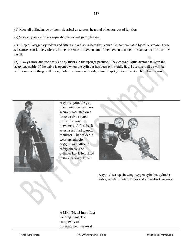
117
Francis Agha Nnachi NAFCO Engineering Training [email protected]
(d) Keep all cylinders away from electrical apparatus, heat and other sources of ignition.
(e) Store oxygen cylinders separately from fuel gas cylinders.
(f) Keep all oxygen cylinders and fittings in a place where they cannot be contaminated by oil or grease. These
substances can ignite violently in the presence of oxygen, and if the oxygen is under pressure an explosion may
result.
(g) Always store and use acetylene cylinders in the upright position. They contain liquid acetone to keep the
acetylene stable. If the valve is opened when the cylinder has been on its side, liquid acetone will be will be
withdrawn with the gas. If the cylinder has been on its side, stand it upright for at least an hour before use.
A typical portable gas
plant, with the cylinders
securely mounted on a
robust, rubber-tyred
trolley for easy
movement. A flashback
arrestor is fitted to each
regulator. The welder is
wearing suitable
goggles, overalls and
safety shoes. The
cylinder key is left fitted
to the oxygen cylinder.
A MIG (Metal Inert Gas)
welding plant. The
complexity of
thisequipment makes it
A typical set-up showing oxygen cylinder, cylinder
valve, regulator with gauges and a flashback arrestor.

118
Francis Agha Nnachi NAFCO Engineering Training [email protected]
suitable for use only by
experienced workers.
A suitable flashback arrestor for use with portable
trolley-mounted gas plants or individual pipeline outlets.
There are also other suitable models and types to protect
branch lines, ring mains, manifold and storage cylinders.
Some include a temperature cut-off valve which is
activated by an external fire. Reputable equipment
suppliers will be able to recommend particular models
for particular situations
Outlet valves, showing left-hand and right-hand threads.
Hazards and how to avoid them
HERE ARE the main hazards encountered in gas welding and cutting and how you can avoid them.
Injuries from burns during and after welding

119
Francis Agha Nnachi NAFCO Engineering Training [email protected]
Wear protective clothing. Never point a torch towards any other person. Chalk a warning onto hot metal so that
others will not touch it or stand on it.
Injuries from backfires of blowpipes and explosions in hoses and equipment
Only use equipment in good condition. Light up only as set out on p.14 of this booklet. Fit flashback arrestors to
equipment.
Explosion of gas-air mixtures in workshops
These generally result from leaking hoses or from connections not being gas-tight. If there is a smell of gas in the
workshop, do not light up until the cause has been found and rectified and the area has been well ventilated to clear
away any residual gases.
Fires in the work area and vicinity
Good housekeeping is essential. There should be no flammable liquids (including solvents or liquefiable solids)
waste or flammable materials in the area, or piles of rubbish in which sparks may smoulder.
Do not leave a lighted torch unattended, or hung over the gas bottles or regulators.
Oxygen-enriched atmosphere
A small increase in oxygen content of the air will cause fierce burning of flames and sparks. Avoid allowing the air
to become oxygen-enriched.
Fumes and gases
These are not a problem in a well-ventilated workshop. But, in confined spaces, carbon monoxide can be a hazard. It
comes from the incomplete combustion of acetylene, and from the welding or cutting of metal covered with paints,
varnish, resins, or carbonaceous materials such as bitumen.
Carbon monoxide has no smell to warn of its build-up. Early symptoms may be a headache or sleepiness. At carbon
monoxide levels near the threshold limit of 50 ppm (parts per million) the symptoms are a lack of concentration and
co-ordination, and then unconsciousness.
Fumes of all descriptions should be disposed of promptly, especially those from zinc and lead oxides. These are
given off when flame is applied to metals primed with zinc and lead paints. No one should be exposed to fumes from
zinc, lead, brass, bronze, copper, nickel, arsenic, cadmium, manganese, phosphorus, selenium, silicon, beryllium,
mercury, fluorine, or stainless steels.
Good workshop ventilation coupled with mechanical extraction devices or breathing apparatus, is necessary.
Eye injuries
Suitable eye protection must be provided by employers and worn by workers. There are types available, with either
tinted or clear lenses, to suit all types of work. If in doubt, ask for advice from the manufacturer and/or supplier.
Use only the correct type of eye protection for the job.

120
Francis Agha Nnachi NAFCO Engineering Training [email protected]
QUESTION 7.1
Give FOUR reasons why the neutral of low voltage system is earthed.
Answer
1. Voltages of the healthy phases do not exceed line to ground voltages i.e they remain nearly constant
2. The high voltage due to arcing ground are eliminated
3. The protective relays can be used to provide protection against earth faults.
4. The over-voltages due to lightning are discharged to earth
5. It provides greater safety to personnel and equipment
6. It provides improved service reliability
7. Operating and maintenance expenditures are reduced
QUESTION 7.2
Describe the construction, mounting principles of operation and maintenance of a Buchholtz relay, and conditions for
which it will provide protection. Use neat labeled sketches to aid your description. (6 marks)
ANSWER
Buchholz Relay Protection description
Buchholz relay is a gas-actuated relay installed in oil immersed transformers for protection against all kinds of faults.
This is a relay, within a cast iron/aluminium casing that is situated in the pipe between the main tank and the
conservator of a transformer as shown in figure (a). It is a universal practice to use Buchholz relays on all such oil
immersed transformers having ratings in excess of 750 kVA. They are also used in Neutral earth compensators
(NECs)
b
a
121
Francis Agha Nnachi NAFCO Engineering Training [email protected]
Construction
Figure (b) shows the constructional details of a Buchholz relay. It takes the form of domed vessel placed in the
connecting pipe between the main tank and the conservator. The device has two elements. The upper element consist
of a mercury type switch attached to a float. The lower element contains a mercury switch mounted on a hinged type
flap located in the direct path of flow of oil from the transformer to the conservator. The upper element closes an
alarm circuit during incipient faults whereas the lower element is arranged to trip the circuit breaker in case of severe
internal faults.
Operation: the operation of Buchholz relay is as follows
(i). In case of incipient faults within the transformer, the heat due to fault causes the decomposition of some of
transformer oil in the main tank. The products of decomposition contain more than 70% of hydrogen gas. The
hydrogen gas being light tries to go into the conservator and in the process gets entrapped in the upper part of relay
chamber. When a pre-determined amount of gas gets accumulated, it exerts sufficient pressure on the float to cause it
to tilt and close the contacts of mercury switch attached to it. This completes the alarm circuit to sound an alarm.
(ii). If a serious fault occurs in the transformer, an enormous amount of gas is generated in the main tank. The oil in
the main tank rushes towards the conservator via the buchholz relay and in doing so tilts the flap to close the contacts
of mercury switch. This completes the trip circuit to open the circuit breaker controlling the transformer.
===================================================================================
November 2008
==================================================================================
Question
Other than energy-saving, state TWO advantages of raising power factor of industrial loads.
Answer
1. Reduce utility power bills
2. Increase system capacity – it releases system capacity and permits additional loads to be added without
overloading the system
3. Improves system operating characteristics (Gain Voltage) – a good power factor (0,95) provides a stiffer
voltage, typically a 1 - 2 % voltage rise can be expected when p.f is brought to +/- 0.95. excessive voltage
drop can make your motors sluggish and cause them to overheat
4. Improve system operating characteristics (reduce line losses)
5. Increase earning capacity of the power station
Question
Two 5MVA transformers are placed in a transformer yard close to a coal handling plant and forms part of a
substation that feeds the coal-handling plant. Draw up a maintenance schedule for the transformers.

122
Francis Agha Nnachi NAFCO Engineering Training [email protected]
Answer
These causes of concern in this question are coal and coal dust. The coal is a major fire hazard and the coal dust
constitutes clogging and blocking hazard, as well as an explosion danger. Over and above this, coal has the
propensity of spontaneous combustion, especially if there is an outside heat source.
Thus the maintenance schedule has to ensure that:
1. Transformer vents to no become blocked with the dust
2. Dust doesn’t accumulate on the transformers,
3. Transformers do not run hot,
4. Terminals are so made off as to preclude any chance of arcing,
5. Transformer oil does not contain moisture.
Question
Compile a safety procedure in a 22kV substation before switching operations may take place.
Question
Each distribution board in an electrical installation shall be controlled by a switch disconnector. State FIVE
requirements for the switch disconnector
Answer
a) Be mounted in or next to the distribution board,
b) In the case of the main or first distribution board of an installation, be labelled as "main switch",
c) In the case of a sub-distribution board, be labelled as "sub-main switch" or “main switch” if the board is labelled
“sub-board …”,
d) In the case where an alternative supply is installed (emergency supply, uninterruptible power systems (UPS), etc.),
be labelled as required in 7.12.2.1 (Where any form of alternative supply (emergency supply, UPS,etc.), is connected
to an electrical installation, a notice to this effect shall be displayed at the main switch of the installation and where
such supply
- automatically supplies power to circuits in the distribution board, a visible indicator shall be provided on each
distribution board where such circuits are live after the main switch on that board has been switched off, and
- only affects a part of the installation, the notice shall also be displayed on the distribution board of that part),
and
e) Have a danger notice on or near it. The danger notice shall give instructions that the switch-disconnector be
switched off in the event of inadvertent contact or leakage.

123
Francis Agha Nnachi NAFCO Engineering Training [email protected]
Question
What consideration shall be taken to determine the type of wiring and methods of installations in an electrical
installation?
Answer
The type of wiring and methods of installation shall be determined after consideration of the following:
a) The location (also consider intentional or inadvertent damage);
b) The nature of the building elements for supporting the wiring;
c) The accessibility of the wiring to persons and livestock;
d) The voltage;
e) The electromechanical stresses and thermal effects likely to occur as a result of short-circuits; and
f) Stresses imposed on the wiring during installation and in service.
==================================================================================
June 2008
==================================================================================
============================================================================
Question 2.2
There is an increase in three-phase standby generator installations to provide electricity in case of mains power
failure. Draw a wiring diagram for a low voltage generating set with the local supply network using the following:
An automatic change-over switch, (6marks)
A manual change-over switch. (4 marks)
Answer
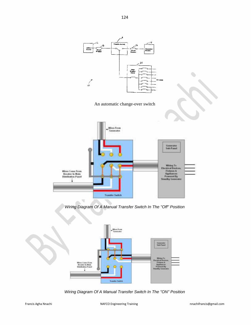
124
Francis Agha Nnachi NAFCO Engineering Training [email protected]
An automatic change-over switch
Wiring Diagram Of A Manual Transfer Switch In The "Off" Position
Wiring Diagram Of A Manual Transfer Switch In The "ON" Position
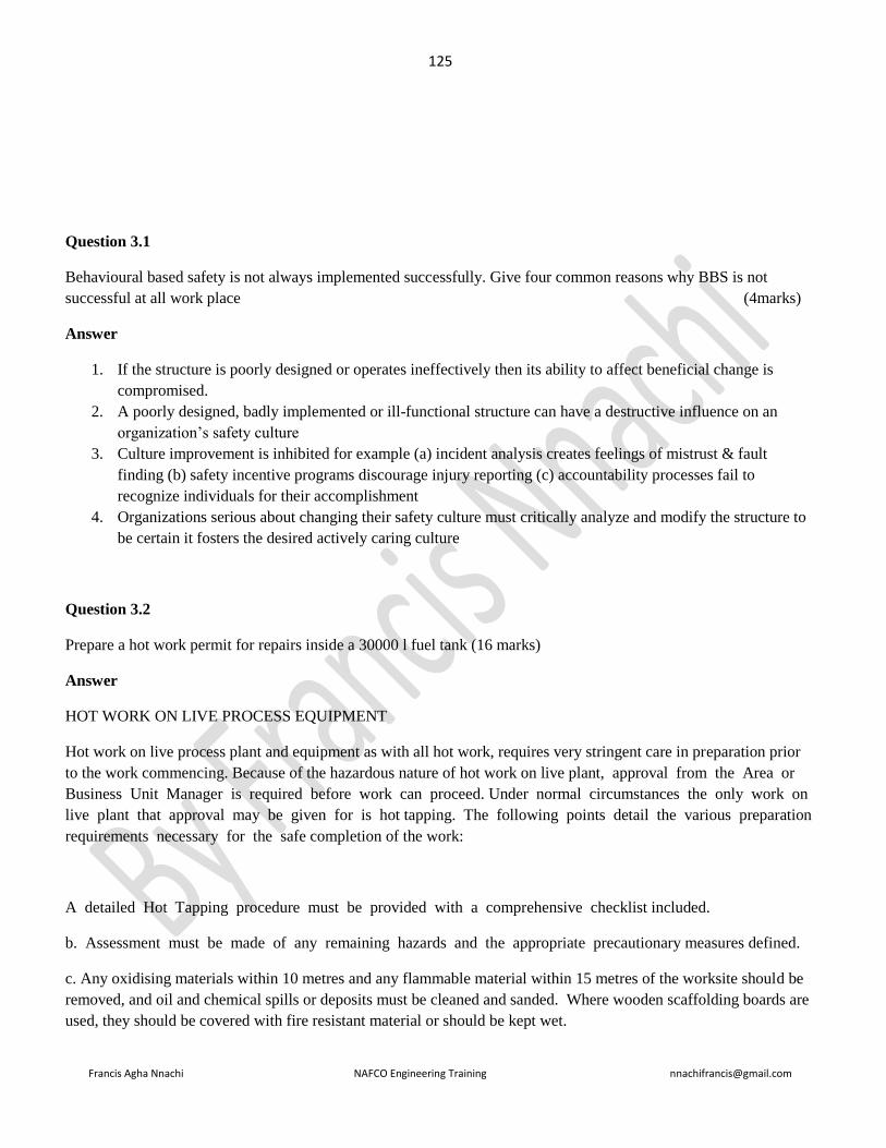
125
Francis Agha Nnachi NAFCO Engineering Training [email protected]
Question 3.1
Behavioural based safety is not always implemented successfully. Give four common reasons why BBS is not
successful at all work place (4marks)
Answer
1. If the structure is poorly designed or operates ineffectively then its ability to affect beneficial change is
compromised.
2. A poorly designed, badly implemented or ill-functional structure can have a destructive influence on an
organization’s safety culture
3. Culture improvement is inhibited for example (a) incident analysis creates feelings of mistrust & fault
finding (b) safety incentive programs discourage injury reporting (c) accountability processes fail to
recognize individuals for their accomplishment
4. Organizations serious about changing their safety culture must critically analyze and modify the structure to
be certain it fosters the desired actively caring culture
Question 3.2
Prepare a hot work permit for repairs inside a 30000 l fuel tank (16 marks)
Answer
HOT WORK ON LIVE PROCESS EQUIPMENT
Hot work on live process plant and equipment as with all hot work, requires very stringent care in preparation prior
to the work commencing. Because of the hazardous nature of hot work on live plant, approval from the Area or
Business Unit Manager is required before work can proceed. Under normal circumstances the only work on
live plant that approval may be given for is hot tapping. The following points detail the various preparation
requirements necessary for the safe completion of the work:
A detailed Hot Tapping procedure must be provided with a comprehensive checklist included.
b. Assessment must be made of any remaining hazards and the appropriate precautionary measures defined.
c. Any oxidising materials within 10 metres and any flammable material within 15 metres of the worksite should be
removed, and oil and chemical spills or deposits must be cleaned and sanded. Where wooden scaffolding boards are
used, they should be covered with fire resistant material or should be kept wet.

126
Francis Agha Nnachi NAFCO Engineering Training [email protected]
d. The cleanliness of the surrounding area and atmosphere must be confirmed by conducting tests for flammable,
toxic and/or oxygen deficient atmospheres. This should be carried out by an Authorised Gas Tester. A maximum of
5% LEL is an acceptable threshold level for Hot Work.
e. The preparation, authorisation and issue of a Hot Work Certificate and Work Permit are issued only after full
consideration is given to the impact and possible conflict with other work which may be progressing in the same
vicinity.
f. Drain covers within 15 metres of the Hot Work site should be covered with a fire resistant blanket, which forms a
seal across the whole opening to prevent the escape of flammable vapours from the drainage systems, and the entry
of sparks into the drain. Sand should be used to seal the blanket edges.
g. Any open drain or ditch running within 15 metres of the Hot Work site should be dammed at locations not nearer
than 15 metres from the worksite and pumped out.
h. Any potential sources of flammable vapour or gas, such as sample points, vents, drains, or relief valve outlet
situated within 15 meters of the Hot Work site should be rendered safe by locking off or plugging, or by taking
the equipment out of commission. If there is any likelihood of flammable vapour or gas release from an
adjacent site, the atmosphere at the Hot Work site should be continuously monitored by a gas detector which
alarms on detection.
i. The Work Permit shall show precautions to be taken while work is in progress, and the Hot Work Certificate shall
show the need for a gas test and continuous gas test monitoring and whether a watchperson is required.
j. Specifying the tools, equipment and techniques to be used. Where sparks may be projected from the immediate
Hot Work site by the use of grinders, or where work is being carried out at height, suitable precautions should be
taken to contain sparks, molten metal and weld spatter, by surrounding the worksite with a fire resistant material.
k. Siting of mobile plant required to allow the Hot Work to proceed, such as welding generators and air
compressors, should be located in a safe area. If they are located within a restricted area they should be subject to
control using a Hot Work Permit.
l. Appropriate fire protection equipment should be located at the Hot Work site. For normal hot work a 9kg dry
powder extinguisher will suffice, however, for Hot Tapping the consequences of an incident will be far
greater so there will be a need to be additional equipment available.
m. Personal Protective Equipment should be stipulated on the Work permit and provided to meet the specific
hazards of the work task.
n. The Permit Holder shall sign both Work Permit and the Hot Work Certificate acknowledging the receipt
of both documents and acceptance of the work precautions and conditions.
o. The Permit Holder shall brief the work party on the job task and precautions to be taken and have them sign the
back of the Work Permit in acknowledgement.
p. The Fire Watchperson shall sign the Hot Work Certificate acknowledging that they have been briefed and are
aware of their responsibilities.

127
Francis Agha Nnachi NAFCO Engineering Training [email protected]
q. When work is suspended for a substantial period such as a lunch break or overnight the power source is to be de-
energised by:
1. removing electrodes from holders and place holders where they will not produce accidental arcing.
2. isolate valves and remove hoses from gas cutting equipment
From other source
1. Identify the hazards and asses the risk
2. Ensure appropriate competency of personnel who will carry out the work
3. Define risk control measures – state the precautions and personnel protective equipment needed
4. Determine communication procedures
5. Identify a procedure and initiate a permit to work
6. Obtain formal approval to perform the work
7. Carry out pre-work briefing
8. Prepare the work
9. Carry out the work to completion
10. Return work site to a safe condition
11. Complete the process, keeping records for audit purposes
Question 4.1 (repeated Nov 2011 Q5.1)
State SIX electrical checks to be done on a medium-voltage circuit breaker during maintenance.
Answer
1. Check the current carrying parts and arcing contacts. If the burning is severe, the contacts should be replaced
2. Check the dielectric strength of the oil, if the oil is badly discoloured, it should be changed or reconditioned.
The oil in good condition should withstand 30kV for one minute in a standard oil testing cup with 4 mm gap
between electrodes.
3. Check the insulation for possible damage. Clean the surface and remove carbon deposits with a strong and
dry fabric
4. Check the oil level
5. Check closing and tripping mechanism
Question 4.2 (repeated Nov. 2011 Q5.2)
Name FOUR acceptable manners how fuses may be used where they are not installed in a distribution board.
Fuses that are not installed in a distribution board shall be
a) Of the fully shrouded type, or

128
Francis Agha Nnachi NAFCO Engineering Training [email protected]
b) In a suitable protecting case, or
c) Incorporated in an appliance or in a socket-outlet, or
d) Incorporated in a switch or in controlgear.
Question 5.2
State three advantages of oil analysis on lubrication for equipment (3 marks)
Answer
• Optimum Equipment Life
• Extended Oil Life
• Reduced Downtime
• Improved Safety
• Environmental Awareness
Question 5.3 repeated Nov. 2001 Q7.b
Name SEVEN types of non-destructive testing to detect defects on metal pressure vessels
Answer
1. Liquid penetrant testing
2. Ultrasonic testing
3. Electromagnetic testing
4. Hardness testing
5. Acoustic emission testing
6. Infrared and thermal testing
7. Magnetic resonance testing
Question 6.1 (repeated June 1990 Q4)
Give a brief description of the advantages and disadvantages of a high-impedance earth protection.
Answer
Advantages

129
Francis Agha Nnachi NAFCO Engineering Training [email protected]
1. Protection is very sensitive and will operate with a high impedance fault or small fault current. This is
important for the safety of the system.
2. The small current causes very little damage at the location of the fault.
3. While a low impedance earth return path should be provided the protection is not wholly dependent on such
a low impedance earth return path.
4. The voltage rise in the faulty equipment is slight because the current in the earth return conductor is small.
5. Because fault voltages and currents are small, the danger of arcing and thereby igniting, gas, vapour or
dust is minimized.
6. The protection is facile and can be made sensitive enough to protect a person that make s a contact with a
live conductor.
Disadvantages
1. The network as a whole is protected, but the protection is not selective.
2. Because the fault currents are small the usual over current protection will not operate and consequently there
is no backup to the earth leakage protection.
3. Care must be exercised that the protection is not made too sensitive as tripping may then be caused by
harmonics, capacity imbalance or induced currents.
4. The inconsequential damage done by the fault current can make it difficult to locate the fault.
5. As the system neutral is not held at earth potential fault conditions may cause the phase-to-neutral insulation
of the equipment to be subjected to the line voltage.
Question 7.1.1
Who shall certify explosion protection apparatus?
Answer
All explosive protection apparatus (EPA) requires a certificate issued by Approved test laboratory (ATL)
All types of explosive protected apparatus shall be independently tested and certified by an ATL
Question 7.1.2
Which property of gas or vapour determines its temperature class?
Answer
Question 7.1.3
Which of the following gases may be present in Group II explosive atmosphere?

130
Francis Agha Nnachi NAFCO Engineering Training [email protected]
Methane (b) Ethylene (c) Acetylene
Answer
b & c
Question 7.1.4
What is the minimum ignition temperature of a gas rated for temperature class T3 (1 mark)
Answer
>200
Question 7.1.5
State two dangers associated with combustible material
Answer
It can burn rapidly when in a finely divided form
If such a dust is suspended in air in the right concentration, it can become explosive, which can cause employees
death, injuries and destruction of entire buildings
Question 7.1.6
State SIX explosion protection techniques used in explosive gas atmospheres
Answer
1. Flame arrestors
2. Intrinsically safe electrical equipment
3. Material/Equipment zoning and separation
4. Heat/smoke/fire detection
5. Adequate ventilation
6. House keeping
Answer from another source
Explosion-protection techniques – techniques applied to the design of electrical equipment, components and systems
to prevent the electrical energy from becoming an ignition source in the presence of flammable vapours and gases or
combustible dusts in explosive atmospheres. See Explosion-protected equipment.
Explosion-protected equipment – electrical equipment to which specific measures are applied to avoid ignition of a
surrounding explosive atmosphere.
Such equipment employs one or more of the following explosion-protection techniques;
Gas atmospheres

131
Francis Agha Nnachi NAFCO Engineering Training [email protected]
Ex d – flameproof;
Ex e – increased safety;
Ex i – intrinsic safety;
Ex n – non-sparking;
Dust
Ex i – intrinsic safety;
Ex t – enclosed;
Ex p – pressurisation;
Pressurisation
Ex p – pressurisation;
Flameproof enclosures
Ex d – flameproof (enclosures);
Coal mining (group I equipment)
Ex dI – flameproof;
Ex eI – increased safety;
Ex iI – intrinsic safety;
Ex t – enclosed (for dust);
Others
Ex o – oil immersion;
Ex m – encapsulation (hermetic sealed);
Ex s – special protection;
Ex v – ventilation;
Ex iD – intrinsic safety (for dust);
Ex mD – encapsulation (for dust);
Ex pD – pressurisation (for dust).

132
Francis Agha Nnachi NAFCO Engineering Training [email protected]
Answer from another source
code
Oil immersion o Type of protection where electrical
equipment is immersed in a
protective liquid in such a way that
an explosive atmosphere that may be
above the liquid or outside the
enclosure cannot be ignited e.g
transformer
pressurized p This type of protection prevents the
surrounding atmosphere from
entering an enclosure by maintaining
a positive pressure within the unit e.g
switching & control cabinet, large
motor
Powder filled q Electrical parts are surrounded with
powder e.g quartz to prevent contact
with an explosive atmosphere e.g
capacitors, fuse etc
Flame proof d Enclosure housing electrical
equipment which, if there is an
internal explosion, will not ignite
surrounding atmosphere e.g control
panels, motor starter, motors, light
fittings
Increased safety e Additional methods are used to
eliminate arcs, sparks and hot surface
capable of igniting flammable
atmosphere e.g. terminal and
connection boxes, light fittings,
squarrel cage motors
Intrinsic safety Ia ib Electrical energy in equipment is
limited so that circuits cannot ignite
on atmosphere by sparking or
heating e.g. equipment e.g sensors,
instruments

133
Francis Agha Nnachi NAFCO Engineering Training [email protected]
Encapsulation m Electrical components embedded in
approved material tp prevent contact
with explosive atmosphere e.g
measurement & control devices,
solenoid valves, electrical
components enclosed in a resin
Type of protection ‘n’ n Non arcing and non-sparking e.g
terminal boxes, light fittings
Question 8.2
The data plate on a boiler has been lost. What procedures shall be followed to replace the data to ensure that the
boiler does comply with the regulations
==================================================================================
November 2007
=======================================================
Question 1.1
Recently, air pollution legislation to reduce the amount of air pollution has increased worldwide. How can harmful
pollutants be removed from the flue gases in a fossil-fuelled power plant? (6 marks)
Answer
Reference is made to coal and products of combustion of coal since coal produces more emission and greenhouse
gases than the other fossil fuels
1. To eliminate CO2 emissions from coal plants, carbon capture and storage has been proposed
2. Fluidized bed coal combustion, furnace sorbent injection and advanced flue-gas desulphurization is
expected to solve some of the major problems emerging from the burning of coal.
3. Fly ash can be removed by fabric bag filters or electrostatic precipitators
4. Sulphur and nitrogen oxide pollutants are removed by stack gas scrubbers

134
Francis Agha Nnachi NAFCO Engineering Training [email protected]
Question 1.2 (repeated June 2015 Q 1.2)
The primary cause of boiler problem is operational. Give FOUR characteristics of feed water for a boiler that should
be checked and state what the ideal values or conditions should be. (4 marks)
Answer
Characteristics to be checked
14. Sediment & turbidity, organic matter; oil & grease
15. Hardneass, calcium (Ca) and magnesium (Mg)
16. Sodium, alkalinity, NaoH, NaHCO3, Na2CO3, sulphates (SO4); chlorides, Cl;
17. Iron (Fe) and manganese (Mn); silica (Si)
18. Ideal values or conditions
19. Feed water-boiler pressure: 69 –103.4
20. Dissolved oxygen (measured before oxygen scavenger addition) : 0.007
21. Total iron-mg/l: 0.01
22. Total copper: 0.01
23. Total hardness (CaCO3): not detectable
24. Non-Volatile TOC: 0.2
25. Oily matter: 0.02
26. pH at 25: 9.0 – 9.6
Question 2.2
Name SIX markings that will be displayed on the drums or reels for electric cables.
Answer:
1. Manufacturers trade name or trade mark or both
2. The rated voltage,
3. the cross sectional area of phase conductors and number of cores
4. length of cable
5. a brief cable description
6. gross mass
7. serial number
8. year of manufacture
9. the instruction “NOT TO BE LAID FLAT”
10. on each flange an arrow with the word “ROLL ON THIS WAY”
11. SABS Mark (if applicable)
12. If the wood of the drum or reel has been treated, a capital “T” of approximately height 50mm surrounded by
a circle of approximately outside diameter 65 mm.

135
Francis Agha Nnachi NAFCO Engineering Training [email protected]
Question 3.1 (repeated Nov 2012 Q3.1)
Behavioral based safety depends on a few basic principles. Name EIGHT of the principles that will ensure effective
implementation of a system
Answer
1. Physical capabilities
2. Experience, and
3. Training
4. Engineering Controls,
5. Equipment,
6. Job task, and
7. The work culture
8. Behavior – what the person does on the job
Question 3.2 (repeated Q3.2 June 2012)
Name SIX outcomes of behavioural based safety
Answer
Typical Outcomes
A well designed and executed Behavioral Safety process should lead to:
1. Reduced numbers of accidents or incidents, near misses and property damage
2. Improved levels of quantified safety behaviors
3. Reduced incident costs
4. Sustainability
5. Acceptance of the system by all concerned
6. The benefit will be far reaching
7. Increased reporting of defects, near misses, accidents
8. Improved Corrective Action rate
9. Improved people skills
10. Better Safety Leadership
Question 3.3 (repeated Nov 2012 Q3.2)
A risk assessment must be done with minimum interruption to customers, before the replacement of a pole-mounted
transformer. Name FOUR hazards associated with this type of work and discuss precautionary measures for EACH
of these hazards. (6 marks)
Answer

136
Francis Agha Nnachi NAFCO Engineering Training [email protected]
No Possible risks, hazards and danger Compulsory required precautionary measures
1 Physical electrical contact during
testing.
i) All equipment used must adhere to OHSAct.
j) Use all test equipment according to prescribed
procedures and manuals.
k) Unauthorised access prohibited (Only PTM
staff, barricading tape, lock gates, etc.)
l) Ensure that plant is properly earthed and that
the earthing arrangement meets the requirement
of the isolations at the point where work has to
be performed.
2
Possible explosion due to flammable
gasses / hazardous chemical
substances: A pole mounted
distribution transformer would in all
likelihood have a hermetically sealed
tank containing flammable oil: this
presents an explosive hazard
Obtain gas test certificate prior to permit to work if
necessary.
Always wear the appropriate personal protective
equipment including fire retardant clothing, hard
hats, safety glasses and rubber gloves
3 High elevated position.
Compulsory use of safety belt / harness is required
when the possibility exists that a person can fall
from an elevated position.
4 Slippery surfaces, oil spillages, leaks,
etc.
e) All slippery surfaces to be cleaned before
commencing with work.
f) Avoid spillages.
5 Unsafe scaffolding.
k) Safe for use sign displayed.
l) Access ladder fitted.
m) No openings in platform.
n) Kick plates fitted.
o) Handrails fitted.
6
Personnel injury:
Components removal, such as a cover.
The cover could go out of control and
hit the line worker; this presents a
falling hazard
Wear PPE: hard hats, safety glasses and rubber
gloves.

137
Francis Agha Nnachi NAFCO Engineering Training [email protected]
7 Oil to skin contact (Skin irritation,
etc.) Avoid oil to skin contact.
8 Unsafe conditions Report any unsafe act / condition
9 Work that needs to be performed
above ground level Complete Q-411 and send to SHEQ office

138
Francis Agha Nnachi NAFCO Engineering Training [email protected]
Question 4.1
Name FIVE requirements for the positioning of electrical equipment in an installation. (5 marks)
Answer
Electrical equipment shall be so positioned that
1. it does not impair the functioning or safety of other equipment,
2. it is readily accessible for installation, replacement, operation, testing, inspection, maintenance and repair.
All parts of the installation shall be accessible without the need to enter any adjoining premises (for example,
in an apartment building), NOTE Common areas (such as passages and entrance halls) are not regarded as
adjoining areas.
3. there is easy access to its location,
4. it is not likely to be physically damaged
5. dust or moisture is not likely to accumulate on live or other parts and cause flashover, and
6. Where the distribution board is concealed by a cupboard or other covering, the notice for live electrical
apparatus referred to in annex Q shall be in a conspicuous place indicating the position of the distribution
board.
Question 4.2
What measures must be taken to provide protection to persons operating electrical switchgear in case of an electrical
arc? (3 marks)
Answer
Question 7.2 (repeated Q7.4 June 2012; Q 5.2 Nov. 2010)
Name TEN visual inspections to be carried out as well as TEN tests with the meaningful readings or results to ensure
a valid certificate of compliance according to the SANS 10142-1: Wiring code of practice for an electrical
installation. (10 marks)
Answer:
During the inspection, confirm that
1. Accessible components are correctly selected
2. All protective devices are of the correct rating,
3. All protective devices are capable of withstanding the prospective short-circuit current

139
Francis Agha Nnachi NAFCO Engineering Training [email protected]
4. Conductors are of the correct rating and current-carrying capacity for the protective devices and connected load
(Pay attention to voltage rating, voltage drop, current-carrying capacity and short-circuit capacity.)
5. Components have been correctly installed, and are accessible where necessary
6. disconnecting devices (isolators) are correctly located and that all switchgear switches the phase conductors,
7. Different circuits are separated electrically. Circuits for control communication, security, detection, safety and
the like, should be electrically separated and, where specified, physically separated,
8. Connections of conductors and earthing and bonding are mechanically sound,
9. Connections of conductors and earthing and bonding are electrically continuous,
10. Circuits, fuses, switching devices, terminals, earth leakage units, circuit-breakers and distribution boards are
correctly and permanently identified, marked or labelled, [Pay attention to installations where circuit-breakers
are used in series-connected (cascaded) systems].
11. The integrity of the fire barrier has been maintained where an electrical system passes through a fire barrier,
12. Safety lighting, emergency lighting and safety signs function correctly,
13. (a) in the case of new installations, or additions or alterations to existing installations, the new, added
or altered installation complies with this part of SANS 10142, or
13. (b) in the case of installations that existed before the publication of this edition of this part of SANS 10142,
the installation complies with the general safety principles of this edition of this part of SANS 10142 and is
reasonably safe, NOTE Indicate (a) or (b) or (a) and (b) on the test report.
14. where an alternative supply is installed, it complies with all the requirements in 7.12, and
15 the position of the readily accessible earthing terminal for the earth connection of other services made by
installers of such services
Testing
1. Continuity of bonding
Test the continuity of the bonding between the consumer's earth terminal and all exposed conductive parts using a
supply that has a no-load d.c. or a.c. voltage of 4 V to 24 V, and a current of at least 0,2 A. In each case, the
resistance shall not exceed 0,2 Ω.
2. Resistance of earth continuity conductor
Use a resistance meter to measure the resistance of the earth continuity conductors between the consumer's earth
terminal and the earthing terminals of all points of consumption and switches. The values shall not exceed those
given in table 8.1.
140
Francis Agha Nnachi NAFCO Engineering Training [email protected]
[All socket-outlets shall be tested by inserting a plug and including the resistance of the earth pin in the
measurements].
3. Continuity of ring circuits
Remove both ends of each live conductor, separate them and test the circuit for continuity. Ensure that the two ends
of the live conductor are connected to the same terminal after the test
4. Earth fault loop impedance at the main switch
At the main switch, the impedance shall be such that an earth fault current double the rated current (or higher) of the
main protective device automatically disconnects the supply to the installation.
5. Elevated voltage on supply neutral
With the main switch off, measure the voltage between the supply neutral and any earth external to the installation.
Notify the supplier if the reading exceeds 25 V. Disconnect the installation and notify the supplier (see annex K) if
the reading exceeds 50 V.
6. Earth resistance
Earth resistance can be determined in accordance with SANS 10199. Where the supplier does not provide an earthing
terminal or where an alternative supply is installed, the efficiency of the earthing system can be confirmed by this
test in SANS 10199. Where the supplier provides an earthing terminal, this test is optional
7. Insulation resistance
Before power is connected to any new or altered circuit, the test for insulation resistance should be carried out to
ensure there is no short-circuit or high impedance faults in the installation, and that it is safe to energize.
8. Voltage, main distribution board — no load
With all load switched off, measure the voltage at the point of control. Notify the supplier (see annex K) if the
voltage is outside the standard voltage limits
9. Voltage, main distribution board — on load
Switch on the maximum available load and measure the voltage at the point of control. Notify the supplier if the
voltage is outside the regulatory limits
10. Voltage at available load
Select the circuit and point of consumption where the worst voltage drop condition is expected. Switch on the
maximum available load, but at least 50 % of the circuit load and not less than 2 A, and measure the voltage at that
point of consumption. Record the value on the test report. The voltage drop from the point of supply to the point
of consumption shall not exceed 5 %.
11. Operation of earth leakage units

141
Francis Agha Nnachi NAFCO Engineering Training [email protected]
Ensure that earth leakage protection is installed in each circuit that is required to be so protected. At various points of
outlet and for each phase conductor of the outlet, pass an a.c. leakage current equal to the rated earth leakage tripping
current (rated residual current) IΔn through a resistance connected between a phase conductor and the earth
continuity conductor. The circuit is protected if the earth leakage unit trips.Repeat the test with a leakage current at
50 % of the rated earth leakage tripping current (rated residual current) IΔn . The earth leakage unit shall not trip.
NOTE: This test can be carried out only after power is available at the point of supply.
12. Earth leakage test button
Press the test button to see that the unit trips.
NOTE: The test is intended to check whether the earth leakage unit is operating correctly, not to check its
sensitivity.
13. Polarity at points of consumption
Ensure that
a) all single-pole switching devices, fuses and circuit-breakers have been connected in the phase conductor,
b) the phase terminals in fixed appliances and in all single-phase socket-outlets have been connected to the phase
conductor,
c) the centre contact of each Edison-screw lamp holder is connected to the phase conductor, and
d) phase rotation and identification is maintained for three-phase systems on the supply sides of all distribution
boards.
14. Switching devices
Ensure that when switching devices are operated, the circuit is interrupted as intended.
Question 8.2
You have to investigate an incident where the rope for a goods hoist has broken. Give FIVE possible causes why the
rope failed and state what will check for in each case
Answer
Since steel wire ropes would be the norm in applications such as this, the comment below is with reference to steel
wire ropes.
1. Rope Strength: the strength of a rope is a function of its size (e.g diameter), grade and construction. Check if
the rope was sufficient to accommodate the load in this application.
2. Fatigue (bending without failure); Fatigue failure of wire rope is caused by the development of small cracks
during small radius bends.
142
Francis Agha Nnachi NAFCO Engineering Training [email protected]
Check for any evidence of small cracks
3. Abrasive wear: the ability of wire rope to withstand abrasion is determined by the size and number of the
individual wires used to make up the rope. Smaller wires bend more readily and offer greater flexibility but
are less able to withstand abrasion. Larger wires are less flexible, but withstand abration better.
Check for evidence of abrasion
4. Abuse: Misuse or abuse of wire ropes will result in their failure long before any other factor. Abuse can lead
to serious structural damage, resulting in kinks or “bird-caging” (in bird-caging” the wire rope strands are
forcibly untwisted and become spread outwards).
Check for any abuse
5. Corrosion: Many steel wire ropes are used outdoors and may be affected by chloride contamination. Even
indoors humidity can cause corrosion.
Check for any evidence of corrosion
============================================================================
June 2007
============================================================================
Question 1.1 (Repeated June 2015 Q 1.1)
Name the function of each of the following and state where each is situated on a boiler plant: (12 marks)
Economiser ; Evaporator; Superheater ; Air preheater
Answer
Economizer: the function of the economizer is to improve efficiency by using waste heat from the flue gas to
preheat the feed water. The feed water is fed through tubes positioned in the flue gases.
These tubes are arranged as a heat exchanger. Fuel saving is of the order of 10 – 15%
Evaporator – the purpose of the evaporator is to distil the feed water to rid it of impurities which would cause
deposits on the tubes. Feed water is fed to the drum through the evaporator which is situated in the flue path of the
boiler or uses heat bled from the turbine in power plants.
Superheater: the steam produced in the boiler is wet and is passed through a superheater where it is dried and
superheated (i.e steam temperature increased above that of boiling point of water) by the flue gas on their to the
chimney. Steam is fed from the drum through the superheater tubes situated in the flue path between the evaporator
and economiser.

143
Francis Agha Nnachi NAFCO Engineering Training [email protected]
Air preheater – Air pre-heater recover the heat from the flue gases by adding it to the air supplied for combustion.
This improves efficiency and lowers the stack temperature. The air pre-heaters are positioned inside the incoming air
ducts and flue gases are passed through a bank of steel tubes to supply the necessary heat.
Question 2.2 (repeated June 2016 Q2.2)
Name FOUR types of applications for a DC series motor and the reason why it is more suitable than other types of
motors. (6 marks)
Answer
1. Hoists.
2. Cranes.
3. Lifts.
4. Electric trains.
Large starting torque and speeds from zero upwards are easily obtainable
Question 2.3
Name FOUR requirements for an over current protective device for an AC electrical motor. (4 marks)
Answer
The over-current protective device shall:
1. Have a tripping value that is as near to the full load rated current of the motor as is practicable;
2. Have sufficient time delay to allow the motor to start and accelerate under normal conditions;
3. Prevent a multiphase motor from continuing to operate under load if a single phasing occurs; and

144
Francis Agha Nnachi NAFCO Engineering Training [email protected]
4. In the case of automatically controlled motor, have to be manually reset after operation before allowing
automatic restarting of the motor.
Question 3
A competent person is part of a project team to assist with the installation of a chrome electroplating plant
Name the FOUR core elements and FOUR supporting elements of project management (8marks)
Almost every project has a three-dimensional goal or objective, namely time, performance and cost. Which ONE will
be the main driver for the above mentioned project? Motivate the answer (4marks)
One of the inputs to a project plant is statutory requirements. Name FOUR statutory acts that may have a direct
implication on the above-mentioned project. Give TWO reasons why you will consider each of these acts. (8 marks)
Answer
Five Essential Elements of Project Management
Initiate. The initiation process authorizes the overall project or the next phase of a project. In this phase, project
objectives are established, scope is defined, and responsible parties and deliverables are identified.
Plan. The planning processes are precisely that--the defining and refining of the best courses of action to take to
attain the project objectives. Planning falls into two categories: core planning processes and facilitating processes.
Core processes are those that have clear dependencies that require them to be performed in essentially the same order
on most projects. Examples include scope planning, schedule development, resource planning, and cost budgeting.
Facilitating processes are entirely dependent on the nature of the project and are performed intermittently and as
needed--though they are not optional. Some of the facilitating planning processes include quality planning, staff
acquisition, and risk identification.
Execute. Planning paves the way for executing, which involves coordinating resources, human and otherwise, to
carry out the overall project plan. Because of the ongoing role execution plays in project management, its processes
are also divided into core and facilitating subgroups. The central core process, project plan execution, oversees
facilitating processes such as team development, information distribution, and solicitation.
Monitor and control. As the figure below shows, controlling processes have a strong presence in all but one of the
project management stages. These processes ensure not only that project objectives are met, but also that corrective
action can be taken should a problem arise. In this phase, performance reporting and risk monitoring and control are
core. These watchdog processes work with facilitating processes such as cost control, quality control, and schedule
control to ensure the project stays on track.
Close. The watchful eyes of the controlling processes eventually lead to closing, where the project is accepted and
brought to an orderly end. The two main components of closing are contract closeout, in which any remaining open

145
Francis Agha Nnachi NAFCO Engineering Training [email protected]
items are resolved and the contract is settled, and administrative closure, the gathering of information to formalize
project completion, including compiling lessons learned for use in future projects.
It is important to note that the individual processes are not one-time events. Rather, they are overlapping activities
that occur at varying levels of intensity throughout the course of the project. Using these standardized project
management practices can help organize any project, and make said project a smoother, less stressful endeavor
Four basic elements of a project:
Resources, time, money, and most importantly, scope
Question 4.1
Name FOUR factors that will change the characteristics of insulation oil inside switchgear when in use (4 marks)
Answer
1. Increased temperatures
2. Absorption of gases, mainly oxygen.
3. Absorption of water from the atmosphere.
4. Particles such as metal, fibres, dust, etc.
Question 4.2
What are the TWO main purposes of using oil inside transformers (2 marks?)
Answer: cooling and insulation
Question 6.2
A new stainless steel heat exchanger has developed severe cracks around the outlet. Name SIX possible causes of
these cracks and discuss each cause.
Answer
All can be attributed to various types of Stress Corrosion Cracking (SCC) as follows:
1) PASCC – Polythionic Acid Stress Corrosion Cracking
2) CLSCC – Chloride Stress Corrosion Cracking
3) Hydrogen Embrittlement
4) Sour Water / Caustic
146
Francis Agha Nnachi NAFCO Engineering Training [email protected]
Question 7.2
There is a need to save energy globally. Give the reasons why energy should be saved. (4 marks)
Answer
By burning fossil fuels for energy, we’re are altering our atmosphere, thereby causing climate change. Every ton of
carbon dioxide pumped into the atmosphere, every coal burning power plant and every energy wasting light bulb
installed makes it harder for us to stop climate change.
Energy costs are concern throughout our economy, and many residents and businesses are already taking measures to
tackle this growing challenge by adopting energy efficient systems and products. Innovative technology can help free
us from our dangerous fossil fuel dependencies
Question 7.3 (repeated Nov 2009 Q2.2)
Discuss common mistakes made that cause wastage of electrical energy in electrical motors. (7 marks)
Answer
• Operating electric motors under less than full load: Induction motors have distinct inefficiencies in that
they cannot effectively adjust the amount of electricity they consume for the work they do. When they
operate under less than full load, substantial power is wasted – a soft starter could be a consideration
• Operating electric motor without a power factor correction: A power factor less than unity results in the
following disadvantages:- Large kVA rating of equipment, greater conductor size, large copper losses, poor
voltage regulation, reduced capacity handling of the system
• Evaluating electric motor usage by load and not including operating hours: Two of the most important
concerns in evaluating energy usage are actual load and operating hours
• Not oversizing of electric motor to ensure load capability results
Question 8.1
The products listed in Table 4.2 of SAN 10142-1: the wiring of premises shall comply with the prescribed standards.
What is the process to obtain approval from SABS for compliance? (12 marks)
Answer

147
Francis Agha Nnachi NAFCO Engineering Training [email protected]
For information, go to www.sabs.co.za on the home page, click on certification & auditing, then click on certification
process.
How to get the SABS Mark
Contact the SABS certification Regional specialists. They will advise you on the right steps to take towards
certification. This includes identifying the relevant SABS mark (performance mark, safety mark, approved
performance, environmental friendliness, packaging and other specialized certification marks) and the relevant
standards, which will set out the characteristics and the performance criteria of your products.
N.B. The product must fall within a SABS/SANS national specification. The product is then fully tested to the
specification. If the product and quality system comply with the requirements, a permit to apply the mark is issued.
However, regular products’ testing is conducted. Assessments of the applicant’s quality system are made at least
twice per year, and feedback of tests results is given.
===================================================================================
November 2006
==================================================================================
Question 1.1 (repeated November 2010 Q1.1)

148
Francis Agha Nnachi NAFCO Engineering Training [email protected]
Name SIX defects or conditions to check for inside a boiler when carrying out a periodic internal inspection and
discuss corrective actions to be taken
Answer
Defects
- Corrosion or cracking of tube sheets, tube ends, furnaces, drums etc
- Cracked fittings
- Erosion
- Scale and deposit: Remove scales and deposits in tubes or the space between the tubes. Internal
feed pipes, dry pans, scrubbers, baffles, chemical feed pipes, surface blowoff and bottom
blowdown connections, and other accessories shall be examined to see that their openings and
perforations are free from deposits
- Broken stays
- Signs of leaking
- Excessive thinning of tubes from repeated rolling (thin places in the drum)
- Grease, oil or similar deposits: Examine the upper half of drums in the steam space for signs of
grease, oil, or similar deposit and clean
- Loose connections of all interior fittings
- Damaged or missing gaskets of all interior fittings
- Fusible plugs damage: Renew fusible plugs, if fitted
The above answer is obtained from the text below
Careful inspection of the internal areas of the pressure parts should be made to detect any corrosion or cracking of
the tube sheets, tube ends, furnaces, or drums, signs of leaking tubes, excessive thinning of the tubes from repeated
rolling, and the condition of any ferrules and nipples within drums. Also note any evidence of corrosion or cracking
due to leakage at manholes or handholes.
Other points to look for when examining the interior of the boiler include cracks, broken stays, cracked fittings,
corrosion, erosion, scale, and thin places in the drums. The upper half of drums in the steam space shall be examined
particularly for signs of grease, oil, or similar deposits.
The interior of the tubes or the space between the tubes shall be examined for scale and deposits. The condition of
all drum internals should be observed. Internal feed pipes, dry pans, scrubbers, baffles, chemical feed pipes, surface
blowoff and bottom blowdown connections, and other accessories shall be examined to see that their openings and
perforations are free from deposits. All interior fittings shall be examined for loose connections and damaged or
missing gaskets.
If fusible plugs are used, see that they are kept in good condition and that they are not used for more than one year

149
Francis Agha Nnachi NAFCO Engineering Training [email protected]
1. Examine the internal seam and water space. Particular attention for O2 pitting around water line.
2. Examine all internal feed pipes for clear passages, also all connections to alarms, controls, gauge glass ports,
steam and water pipes.
3. Where high and low water alarm floats are fitted, the trays must be clean and all linkages free. They must be
operating within the required limits.
4. Painting of the shell of the boiler must not be done until after the internal inspection has been completed.
Renew fusible plugs, if fitted.
5. Tubes and headers must be examined for wastage around the seating inspection and other holes.
Question 2.2
State TWO disadvantages and ONE advantage in using an auto-transformer in place of an isolating transformer. (3
marks)
Answer
Advantages
1. For the same job, autotransformers are superior to isolation-type transfomers.
2. They are smaller in size requiring less excitation current and therefor lower cost
3. They have a greater efficiency due to smaller currents and they provide better voltage regulation
Disadvantages of using autotransformer
1. The direct connection between the high-voltage and low-voltage circuits. Each circuit is directly affected by
the electrical conditions originating in the other. If a ground fault occurs in one, it occurs in both.
Question 2.3
Name FOUR methods in which the cooling area of a transformer can be increase. (4 marks)
Answer
Methods of increasing cooling area of a transformer
1. by providing cooling ducts or tubes
2. By providing radiators/corrugated tanks
3. By designing the transformer with less number of turns
4. By increasing current density

150
Francis Agha Nnachi NAFCO Engineering Training [email protected]
Question 3.1
State SIX general requirements that an occupational health and safety policy should include (6 marks)
Answer
Ensure that the policy
a) is appropriate to the nature and scale of the organization’s OH&S risks;
b) includes a commitment to prevention of injury and ill health and continual improvement in OH&S management
and OH&S performance;
c) Includes a commitment to at least comply with applicable legal requirements and with other requirements to which
the organization subscribes that relate to its OH&S hazards;
d) provides the framework for setting and reviewing OH&S objectives;
e) is documented, implemented and maintained;
f) is communicated to all persons working under the control of the organization with the intent that they are made
aware of their individual OH&S obligations;
g) is available to interested parties; and
h) Is reviewed periodically to ensure that it remains relevant and appropriate to the organization
i) Signed by CEO
Question 3.2 (repeated June 2009 Q3.2.1)
State SIX items or documents to be considered for the planning stage of an OHSMS (6 marks)
Answer
a) Routine and non-routine activities;
b) Activities of all persons having access to the workplace (including contractors and visitors);
c) Human behaviour, capabilities and other human factors;
d) Identified hazards originating outside the workplace capable of adversely affecting the health and safety of
persons under the control of the organization within the workplace;
e) Hazards created in the vicinity of the workplace by work-related activities under the control of the organization;

151
Francis Agha Nnachi NAFCO Engineering Training [email protected]
NOTE 1 It may be more appropriate for such hazards to be assessed as an environmental aspect.
f) Infrastructure, equipment and materials at the workplace, whether provided by the organization or others;
g) Changes or proposed changes in the organization, its activities, or materials;
h) Modifications to the OH&S management system, including temporary changes, and their impacts on operations,
processes, and activities;
i) Any applicable legal obligations relating to risk assessment and implementation of necessary controls
j) The design of work areas, processes, installations, machinery/equipment, operating procedures and work
organization, including their adaptation to human capabilities.
Question 3.3
Discuss the implementation and operation elements of the OHSMS (8 marks)
Answer
1. Resources, roles, responsibility, accountability and authority
2. Competence, training and awareness
3. Communication,
4. participation and consultation
5. Documentation
6. Control of documents
7. Operational control
8. Emergency preparedness and response
Discussion is as shown below
Resources, roles, responsibility, accountability and authority
Top management shall demonstrate its commitment by:
a) Ensuring the availability of resources essential to establish, implement, maintain and improve the OH&S
management system;
NOTE 1 Resources include human resources and specialized skills, organizational infrastructure, technology and
financial resources.
b) Defining roles, allocating responsibilities and accountabilities, and delegating authorities, to facilitate effective
OH&S management; roles, responsibilities, accountabilities, and authorities shall be documented and communicated.
Competence, training and awareness
The organization shall establish, implement and maintain a procedure(s) to make persons working under its control
aware of:

152
Francis Agha Nnachi NAFCO Engineering Training [email protected]
a) The OH&S consequences, actual or potential, of their work activities, their behaviour, and the OH&S benefits of
improved personal performance;
b) their roles and responsibilities and importance in achieving conformity to the OH&S policy and procedures and to
the requirements of the OH&S management system, including emergency preparedness and response requirements
c) The potential consequences of departure from specified procedures.
Training procedures shall take into account differing levels of:
a) responsibility, ability, language skills and literacy; and
b) risk.
Communication, participation and consultation
Communication
With regard to its OH&S hazards and OH&S management system, the organization shall establish, implement and
maintain a procedure(s) for:
a) Internal communication among the various levels and functions of the organization;
b) Communication with contractors and other visitors to the workplace;
c) Receiving, documenting and responding to relevant communications from external interested parties.
Participation and consultation
The organization shall establish, implement and maintain a procedure(s) for:
a) The participation of workers by their:
• Appropriate involvement in hazard identification, risk assessments and determination of controls;
• Appropriate involvement in incident investigation;
• Involvement in the development and review of OH&S policies and objectives;
• Consultation where there are any changes that affect their OH&S;
• Representation on OH&S matters.
Workers shall be informed about their participation arrangements, including who is their representative(s) on OH&S
matters.
b) Consultation with contractors where there are changes that affect their OH&S.

153
Francis Agha Nnachi NAFCO Engineering Training [email protected]
The organization shall ensure that, when appropriate, relevant external interested parties are consulted about
pertinent OH&S matters.
Documentation
The OH&S management system documentation shall include:
a) The OH&S policy and objectives;
b) Description of the scope of the OH&S management system;
c) Description of the main elements of the OH&S management system and their interaction, and reference to related
documents;
d) Documents, including records, required by this OHSAS Standard; and
e) Documents, including records, determined by the organization to be necessary to ensure the effective planning,
operation and control of processes that relate to the management of its OH&S risks.
Control of documents
The organization shall establish, implement and maintain a procedure(s) to:
a) Approve documents for adequacy prior to issue;
b) Review and update as necessary and re-approve documents;
c) Ensure that changes and the current revision status of documents are identified;
d) Ensure that relevant versions of applicable documents are available at points of use;
e) Ensure that documents remain legible and readily identifiable;
f) Ensure that documents of external origin determined by the organization to be necessary for the planning and
operation of the OH&S management system are identified and their distribution controlled; and
g) Prevent the unintended use of obsolete documents and apply suitable identification to them if they are retained for
any purpose.
Operational control
The organization shall determine those operations and activities that are associated with the identified hazard(s)
where the implementation of controls is necessary to manage the OH&S risk(s). This shall include the management
of change (see 1 planning).
For those operations and activities, the organization shall implement and maintain:
a) Operational controls, as applicable to the organization and its activities; the organization shall integrate those
operational controls into its overall OH&S management system;

154
Francis Agha Nnachi NAFCO Engineering Training [email protected]
b) Controls related to purchased goods, equipment and services;
c) Controls related to contractors and other visitors to the workplace;
d) Documented procedures, to cover situations where their absence could lead to deviations from the OH&S policy
and the objectives;
e) Stipulated operating criteria where their absence could lead to deviations from the OH&S policy and objectives.
Emergency preparedness and response
The organization shall establish, implement and maintain a procedure(s):
a) To identify the potential for emergency situations;
b) To respond to such emergency situations.
Question 4.1 (repeated June 2010 Q6.2)
Name FOUR items to check on a steel wire rope used on a gantry crane when carrying out a periodic inspection and
discuss each item (8 marks)
Answer
15. Broken wires: A wire rope must be discarded if the permissible number of wire breaks is reached or
exceeded. It must also be replaced when local concentrations of wire breaks occur.
16. Reduction in diameter: reduction in diameter can be caused by abrasion, corrosion or a local failure of the
rope core.
17. Corrosion: corrosion may be external or internal, general or localized. A wire should be discarded when the
surface of the wires is severely roughened or pitted, or if the wires are slack within the strands due to
wastage.
18. Rope deformation: (a) Waviness: this deformation, while it may not necessarily affect the strength of the
rope, can transmit pulsation and produce uneven rope wear.( b). Birdcage (basket deformation): A birdcage
develops when the outer layer of strands becomes longer than the inner layer or layers. The condition may
occur as a result of incorrect fitting, tight sheaves, shock loading, incorrect use of a swivel or the application
of a heavy load to a new rope before the strands have settled into position. Ropes with a birdcage should be
discarded. (c). Loop Formation: wires or groups of wires may form a line of loops parallel to the axis of the
rope. This deformation is often caused by shock-loading. Loop formations are justification for discard.(d)
Nodes, (e) thining of the ropes, (f) misplaced outer wires, (g) kinks, (h) flat areas
19. Damage caused by heat
From another source
There are a number of ways that a gantry wire rope can deteriorate viz. by wear, corrosion or metal fatigue.

155
Francis Agha Nnachi NAFCO Engineering Training [email protected]
The rope must be inspected both internally and externally. The items to be checked will include
The nature and number of broken wires. whether there are broken wires at the termination
The localized grouping of wire breaks. Whether there is any reduction of rope diameter
All of the above could be caused either by an aggressive and dusty environment, lack of core lubricant or excessive
or continuous shock loading.
Decreased elasticity. This is difficult to detect an increase in rope length and decreased diameter could bring about
this.
External and internal wear. Internal wear can be checked by attaching special clamps to the rope a short distance
apart. These can be twisted against the lay to open up the rope so that an internal inspection can be done
Question 5.2
Give FOUR requirements for the installation of a step-up transformer in an electrical installation. (4 marks)
Answer
If a step-up transformer is used to raise the voltage of the supply (for example, for high-voltage signs but excluding
voltages stepped up in a power installation),
a) The transformer shall be in a suitably labelled enclosure;
b) Except as permitted in 7.13.7.2 for autotransformers, the primary and secondary windings shall be separate
throughout;
c) The circuit that supplies the transformer shall have a multipole switch disconnector that disconnects all the phase
and neutral conductors of the supply; and
d) The equipment shall be so arranged that the length of high-voltage wiring is reduced as much as possible.
Question 5.3
Give FOUR requirements for the installation of a manually operated disconnector for an electrical motor in an
electrical installation (4 marks)
Answer

156
Francis Agha Nnachi NAFCO Engineering Training [email protected]
Question 8.1
You have implemented a predictive maintenance programme at the factory. The following equipment are listed as
critical equipment:
Transformer
Distribution boards
Control systems
Lighting panels.
Handled test tools are used to check the abnormalities. What are the key indicators to look for and what type of
instruments will you use to detect these indicators? (12 marks)
Answer
Unlike regular digital cameras that capture images of visible light reflected
by objects, THERMAL IMAGERS create pictures by measuring infrared
energy or heat. The thermal imager then assigns colours based on the
temperature differences it measures.
With a small amount of training, most people can readily spot abnormal
temperatures and follow the heat trail to energy waste.
Many people don’t realize that electrical systems can actually waste money.
As components degrade and resistance increases, incremental waste occurs.
What to scan:
Transformers: monitor high and low bushing connections, cooling tubes and cooling fans and pumps. Look for
overheated connections, comparatively cool cooling tubes and hot or cold pumps. Be aware that if the temperature of
one electrical leg on a transformer is significantly hotter than the others that leg may be failing.
Distribution Panel: check for unbalance in circuits and loose and corroded connections at breakers, contacts, fuse
clips, busses, etc.
Lighting control circuits: check all wiring splices and connections at fuses, switches, and fixtures. Be aware also
that thermography can also be used to monitor low-voltage control circuits

157
Francis Agha Nnachi NAFCO Engineering Training [email protected]
Question 8.2
Define the term water hammer (3 marks)
Answer
Water hammer (or, more generally, fluid hammer) is a pressure surge or wave resulting when a fluid (usually a liquid
but sometimes also a gas) in motion is forced to stop or change direction suddenly (momentum change). Water
hammer commonly occurs when a valve is closed suddenly at an end of a pipeline system, and a pressure wave
propagates in the pipe. It may also be known as hydraulic shock.
Question 8.3
State FIVE factors that can contribute to water hammer (5 marks)
==================================================================================
June 2006
=======================================================
Question 1.1
What causes poor combustion in a coal fired boiler and how can the combustion be improved (12)

158
Francis Agha Nnachi NAFCO Engineering Training [email protected]
Answer:
For one or more of the following reasons, it is possible for combustion to be incomplete in practical circumstances,
even though there is enough, or even too much, excess air present.
1. Air passes through the furnace without mixing thoroughly with the fuel
2. The fuel is not hot enough to react with the air
3. Fuel and air have not had time to react before the combustion products are being chilled
Combustion should be completed within the furnace and this can only happen when the rule of the three T’s is
strictly adhered to:
1. Time – by allowing sufficient time for the fuel to burn in the hot furnace
2. Temperature – by having the fuel at a sufficient high temperature to burn
3. Turbulence – by mixing the fuel turbulently with sufficient air in the combustion chamber
Question 1.2
Compile a checklist for the operators of a 10 ton/h coal fired boiler that must be used before handing over and taking
over the operation (8 marks)
Answer
Taking over from previous shift:
1. Check boiler pressure
2. Check water level in the boiler
3. Check that the grate is not more than hand-hot and that its color is normal
4. Check ash build up under the stoker via peephole in emergency de-arching door
5. Note under grate damper setting
6. Check ignition of coal through the ignition arch peephole
7. Check that coal is flowing correctly in the stoker hopper
8. Check that the arch trolley is empty. Replace ash trolley and open the ash valve to allow ash to drop into the
ash trolley, then close it
9. Check the length of the fire through the rear peephole. Adjust under grate damper setting if necessary
10. Check that the grit trolley is empty
11. Check that there are enough chemicals in the chemical dosing pump tank for your shift
12. Check that there is salt in the brine tank of the water softener
13. Check the water level in the hot well tank
14. Check the log – enter any defects found during handing over immediately
15. Once the floor area around the boiler has been swept by previous shift, then take over the boiler

159
Francis Agha Nnachi NAFCO Engineering Training [email protected]
Question 2.2
State SIX advantages of a permanent magnet motor (6 marks)
Answer
1. Higher efficiency since no electrical energy is used or losses incurred for developing or maintaining the
motor’s magnetic field.
2. Higher torque and power density
3. Linear torque speed characteristics, that is more predictable.
4. Better dynamic performance due to higher magnetic flux density in air gap.
5. Simplified construction and essentially maintenance-free.
6. More compact size
Question 2.3
State EIGHT advantages of a vacuum circuit breaker (8 marks)
Answer
1. Compact, reliable and have longer life.
2. No fire hazards
3. No generation of gas during and after operation
4. Can interrupt any fault current
5. No noise is produced while operating
6. Require less power for control operation
7. Require little maintenance
8. They can successfully withstand lightning surges
9. They have very low arc energy
Question 3.1
You must establish an inspection plan for an ammonia refrigeration plant room that is classified as a zone 1 location
in terms of SANS 10108. Name SIX actions that you will take to assist you with the inspection plan (6 marks)
Answer
Conducting any type of inspection is one of the system operator’s most valuable tools for preventing unnecessary
accidents due to equipment failure.
Conduct Visual Testing
Visual inspections are relatively inexpensive and provide a great deal of valuable information to the system operator.
To monitor the condition of the ammonia refrigeration system, the person inspecting the system should note any
corrosion of piping, valves, seals, flanges, and other pertinent equipment. In addition, the insulation should be

160
Francis Agha Nnachi NAFCO Engineering Training [email protected]
visually inspected for breeches in it’s integrity. The person conducting the visual test should keep a log, including
photographs, of all findings.
Conduct Leak Testing
All ammonia refrigeration system operators should try to maintain a leak-free ammonia system. Recommended
practice involves leak testing all piping, valves, seals, flanges, and other pertinent equipment at least four times a
year. Some methods that can be used for leak testing are sulfur sticks, litmus paper, or a portable meter equipped
with a flexible probe.
Operators, maintenance personnel, and other facility workers should be encouraged to immediately report ammonia
odors. Facilities should immediately investigate all reports of ammonia leaks, and take corrective actions without
delay.
Conduct Vibration Testing
Depending on the nature of equipment at the site, some facility operators may elect to perform vibration testing on
rotating equipment (i.e., compressors and pumps). These are usually performed to supplement the maintenance
practices to indicate when equipment overhauls should be performed. Vibration levels on certain equipment can be
logged and analyzed to determine if abnormal trends are developing or if further inspections are warranted.
Excessive vibration can lead to potential equipment damage which could increase the probability of an ammonia
release. The equipment manufacturer should be consulted to provide guidance on the usefulness of vibration
monitoring for their particular equipment.
Conduct Thermal Imaging
A growing trend in preventive maintenance is the use of infrared (thermal) imaging. Infrared thermography helps
locate many problems in their early stages often before they can be seen or found in any other way. A temperature
difference, usually an abnormal hot spot, is typically associated with these problems due to high electrical resistance
or excessive friction
Question 3.2
What are the most non-conformities found on electrical machinery in a hazardous location? (3 marks)
Answer:
Question 3.3

161
Francis Agha Nnachi NAFCO Engineering Training [email protected]
What actions must be taken to ensure that the refrigeration plant is kept in a safe condition (5 marks)
Answer
Question 3.4
What are the requirements with regards to personal protective equipment in terms of SANS 10147
Answer
Question 4.2
A solenoid-operated hydraulic valve fails to operate. Name Four possible causes with appropriate corrective actions
(8marks)
Answer
Question 5.2
You have to carry out an earth fault loop impedance test on a low voltage electrical installation
5.2.1 Explain the purpose of an earth loop impedance tests with the aid of a sketch and how maximum limit is
calculated (6 marks)
5.2.2 What action will you take if the above test results are above prescribed limit (2 marks)
Answer
Fault loop impedance tests
This test indicates whether the various protective devices, will operate satisfactorily in the event of a fault.
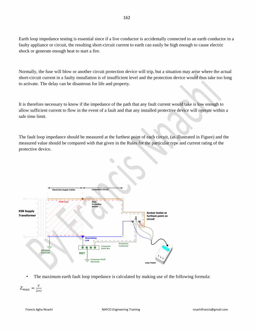
162
Francis Agha Nnachi NAFCO Engineering Training [email protected]
Earth loop impedance testing is essential since if a live conductor is accidentally connected to an earth conductor in a
faulty appliance or circuit, the resulting short-circuit current to earth can easily be high enough to cause electric
shock or generate enough heat to start a fire.
Normally, the fuse will blow or another circuit protection device will trip, but a situation may arise where the actual
short-circuit current in a faulty installation is of insufficient level and the protection device would thus take too long
to activate. The delay can be disastrous for life and property.
It is therefore necessary to know if the impedance of the path that any fault current would take is low enough to
allow sufficient current to flow in the event of a fault and that any installed protective device will operate within a
safe time limit.
The fault loop impedance should be measured at the furthest point of each circuit, (as illustrated in Figure) and the
measured value should be compared with that given in the Rules for the particular type and current rating of the
protective device.
Socket Outlet at
furthest point on
circuit
ESB Supply
Consumer Earth
Electrode
Protective
Conductor
MET
Consumer
Earth Bar
Neutralising
Link
ESB Earth
Electrode
Main
Protective
Device
Fault Loop
Loop Tester
Electricity Supply Cables Consumers Circuit
Transformer
• The maximum earth fault loop impedance is calculated by making use of the following formula:
𝑍𝑚𝑎𝑥 =𝑉
2×𝐼

163
Francis Agha Nnachi NAFCO Engineering Training [email protected]
Where = size of main circuit breaker
For example: A main breaker of 60A should disconnect at a maximum loop impedance value of:
𝑍 =𝑉
2×𝐼 ; 𝑍 =
230
2×60= 1.92Ω 𝑚𝑎𝑥
The maximum earth fault loop impedance can then be determined using the following formula:
Where Zs is the earth fault loop impedance, Ze is the external earth fault loop impedance, R1 is the resistance of the
phase conductor from the origin of the circuit and R2 is the resistance of the earth conductor from the origin of the
circuit.
where IFMax is the fault current (maximum) and Uo is the nominal line voltage to earth (230V).
Question 7.2
Name FOUR types of mechanical power transmission equipment and for each type give the common maintenance
error (10 marks)
Answer
Screws, Wedge, Pulleys, Belts, Cam, Gear, Gear box, Walking beam, Hoppers, Pneumatics and hydraulics, Motors
etc
Question 8.2
Where will you hard-stamp a gas cylinder? Motivate your answer (3 marks)
Answer
Question 8.3

164
Francis Agha Nnachi NAFCO Engineering Training [email protected]
When must a gas cylinder with a design working pressure below 3500 kPa be pressure tested (3 marks)
Answer
===================================================================================
November 2005
==================================================================================
Question 1.1
Draw up a specification for the buyer to order the coal required for a new 10 ton chain-grate packaged boiler,
including an estimate of the quantities required per month for an average continuous steam usage of 9.5 tons per hour
(8 marks)
Answer
Purchase specification for coal
Coal specification Ash content by mass:
Maximum = 35%
Minimum = 25%
Calorific value
Minimum = 27 MJ/kg
Moisture content:
Maximum = 6%
Minimum = 0%
Particle size distribution:
+100 mm = 0%
+50 mm = 10%
-6 mm = 50%
Quantities (contractual expextations)
– the order quantities may be altered
to maintain a minimum stockpile
quantity.
Monthly average = 7.1 Mt/mo
Monthly maximum = 8.5 Mt/mo
Monthly minimum = 5.7 Mt/mo
Order quantity required for the
month of xxxx will be provided by
operations to maintain specified
stockpile quantities
The coal specifications, as well as the supply rates and contract details will depend on the coal specifications defined
by the supplier of the chain grate packaged boiler, as well as by preliminary negotiations with the mine. Thus the
details given are similar to those that could be given to the buying department. The order quantities and may be

165
Francis Agha Nnachi NAFCO Engineering Training [email protected]
reduced outages and will vary during winter when peak demands may be expected and summer when demand is
reduced. To ensure that stockpiles are maintained within specified limits the order quantities will be specified
according to expected usage, and stockpile quantities.
Question 1.2
Make a sectioned sketch and explain the working of a mechanism which controls the required movement of a
sootblower (12 marks)
Answer
Sootblowers are used to remove ash/clinker which has built up on the tubes, or other components of a boiler.
During the operation of a boiler clinker/ash is deposited on the boiler tubes and other parts of the boiler, which in the
case of the boiler tubes, increases the thermal resistance of the heat transfer from the hot gases of combustion to the
water or superheated steam in the boiler tubes, thereby reducing the efficiency of the boiler.
Sootblowers are used from time to time to remove the build up of clinker
Soothblowers operate by blowing steam into areas where the clinker/ash is to be removed. The steam in the
sootblowers is at a higher pressure than the ambient pressure in the boiler and steam is blown into the boiler at high
speed. The speed of the steam is sufficiently high to cause erosion on the boiler tubes and care should be taken to
avoid impingement of the steam onto the boiler tubes.
The temperature of the steam will usually be lower than the temperature of the areas to be cleaned. The different
temperature, which is usually lower than that of the area to be cleaned results in the thermal stresses in the
clinker/ash which causes the deposit to break and drop off the boiler tubes or other parts of the boiler.
Question 2.2
Discuss the principles and features of a SCADA (8 marks)
Answer
A Supervisory Control and Data Acquisition (SCADA) system, as the name implies, collects performance data from
a system, such as electricity generation and distribution system, and provides information or input signals to control
the operation of the system, such as matching the level of energy demand to the level of generation. A simplified
SCADA configuration is shown in diagram below
Transducers Transducers
Data analysis and comparison unit
Transmission lines

166
Francis Agha Nnachi NAFCO Engineering Training [email protected]
Schematic diagram of a simplified SCADA system
Being computer based the system can be set to control the operational against defined parameters and control
algorithms.
The principles of SCADA system will include:
SCADA systems collect operational data to measure the performance of a system as specified by operational
requirements
The data is collected according to defined parameters which allow the system to be operated efficiently.
A SCADA system is essentially a computer based system for measuring, comparing, and controlling the performance
of a system against preset parameters
Incorporating feed-back, SCADA system can operate on a closed-loop system.
Features of a SCADA System will include:
Monitoring system security and operational limits
Raising alarms where necessary either electronically, or as an interface with operators
Supervisory control adjusting operational parameters, such as turbine control valve settings to ensure power is
maintained and system voltage frequency is maintained within set limits
Provision of user interface features such as performance data and plots, and guidelines of suggested actions.
Question 3.1
Accident investigations frequently identify a failure to manage changes adequately as a contributory cause. Discuss
the statement (10 marks)

167
Francis Agha Nnachi NAFCO Engineering Training [email protected]
Answer
Question 3.2
It is common for accident investigators to state: ‘the injured person was responsible for his/her own injuries’. Discuss
this statement (10 marks)
Answer
Question 4.2
Briefly describe using appropriate sketches where necessary, the manufacture of all the components, the assembly,
charging and electrical testing of a typical automotive lead-acid battery (8 marks)
Answer
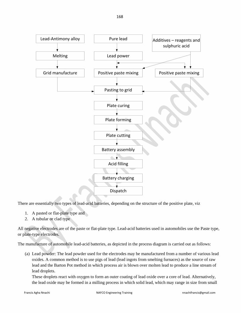
168
Francis Agha Nnachi NAFCO Engineering Training [email protected]
Lead-Antimony alloy
Melting
Grid manufacture
Pure lead
Lead power
Positive paste mixing
Additives – reagents and sulphuric acid
Positive paste mixing
Pasting to grid
Plate curing
Plate forming
Plate cutting
Battery assembly
Acid filling
Battery charging
Dispatch
There are essentially two types of lead-acid batteries, depending on the structure of the positive plate, viz
1. A pasted or flat-plate type and
2. A tubular or clad type
All negative electrodes are of the paste or flat-plate type. Lead-acid batteries used in automobiles use the Paste type,
or plate-type electrodes.
The manufacture of automobile lead-acid batteries, as depicted in the process diagram is carried out as follows:
(a) Lead powder: The lead powder used for the electrodes may be manufactured from a number of various lead
oxides. A common method is to use pigs of lead (lead ingots from smelting furnaces) as the source of raw
lead and the Barton Pot method in which process air is blown over molten lead to produce a line stream of
lead droplets.
These droplets react with oxygen to form an outer coating of lead oxide over a core of lead. Alternatively,
the lead oxide may be formed in a milling process in which solid lead, which may range in size from small

169
Francis Agha Nnachi NAFCO Engineering Training [email protected]
balls to complete pigs, is tumbled in a mill. The heat generated from the friction oxidises the surface of the
lead which is removed to expose clean regions of lead which are then oxidised.
(b) Grid production: the function of the grids is to hold the active material, viz the lead oxide paste, and to
collect electric charge during the charging process, and to disvharge electric charge during the disvharge
process. The grids are produced mainly by casting or from expansion from wrought or cast lead alloy.
(c) Pasting: the lead oxide pastes are prepared by blending lead powder, dilute sulphuric acid, and proprietary
additives in a mixing machine. The paste is formed by a press, or by hand, into the grid lattice and the plates
are usually flash-dried in a high temperature oven. Pasted plates are cured in ovens undercontrolled
conditions when any free lead is oxidised to lead oxide.
(d) Formation plate cutting and assembly: formation is a process in which cured plates are electrolysed to form
PbO2 for the positive electrodes and sponge lead for the negative electrodes. The plates are then cut
assembled, with separators between them, into battery boxes. Plates of similar polarity are connected by
welding plate lugs.
(e) Acid filling and charging: finally, the batteries are filled with sulphuric acid with specific gravity of 1.36 to
1.38, and charged.
Question 4.3
Discuss the difference between the electrical characteristics of a typical automotive battery and a traction battery and
describe how these different characteristics are achieved (4 marks)
Answer
Traction or motive batteries are used for traction purposes, that is, the power from the battery is used as the motive
power for the vehicle, and not to aid the operation of a power system, such as a petrol engine in which the motive
power is derived from another energy source such as petrol.
Traction batteries would typically be used in mine locomotives, tractors, shuttle cars, floor-cleaning equipment,
lawnmowers, and golf-carts. The discharge rates required for the variety of vehicles which use batteries for traction
power varies considerably and no single type of lead-acid battery can satisfy the diversity of applications, and
different designs are required for the different discharge requirements.
Traction batteries need to have high discharge rates for a given period, typically 6 hours. They are:
• Automobile lead-acid batteries typically have energy densities of the order of 28 Wh/kg to 48 Wh/kg with
respect to battery mass, and 50 Wh/l to 100 Wh/l.
• Traction lead-acid batteries typically have energy densities of the order of 19 Wh/kg to 24 Wh/kg with
respect to battery mass, and 60 Wh/l to 85 Wh/l. thus energy densities of automotive batteries are higher than
those of traction batteries, allowing less loading of the materials in the traction batteries.

170
Francis Agha Nnachi NAFCO Engineering Training [email protected]
• Typically cycle life of an automotive battery is 150 to 250 cycles while that of a traction battery is 1000 to
2000 cycles.
• Processing methods for motive power cells are similar to those used in manufacturing other lead-acid
batteries, but the cell construction is different to achieve a longer cycle life.
• For example, the positive plates are vertically and horizontally wrapped with a glass-silver tape and
fibreglass mats to reduce shedding of the positive material under abusive operating conditions.
• Also, additional protection is achieved by encasing the positive plates with perforated plastic envelopes
which have solid edges to reduce the occurrence of ‘moss’ shorts. To further reduce chances of shorting, the
bottom of each positive electrode is housed in a plastic shield.
• Synthetic micro porous separators are used between cell plates. These separators are ribbed and placed
against the positive electrodes to facilitate unrestricted flow of electrolyte.
• A comb-shaped element protector is positioned above the plates to prevent top ‘moss’ shorts, and damage to
the cell when objects such as hydrometers are inserted into the cells.
• The sediment bridge is designed to allow setting of sediment uniformly in the battery to reduce shorting of
plates by the sediment.
• Lightweight construction using high-impact plastic allows for a higher energy density
Question 5.1
With reference to electrical systems, what do the abbreviations SELV and PELV stand for? (2 marks)
Answer
SELV – Safety Extra Low Voltage. A SELV system is a low voltage system where the output is isolated from the
input.
PELV – Protective Extra-Low Voltage. A PELV system is a low voltage system but it is connected to earth for
protection
Question 5.2
One of the measures listed in SANS 10142-1 to provide protection to people, animals and property against harful
earth currents, is electrical separation of circuits. Explain what this means and discuss the limitations of this measure
for long circuits. (3 marks)
Answer
The term electrical separation of a circuit means that the circuit is electrically isolated from other circuits in the
installation. The risk of one of the conductors faulting to earth is increased as the length of the conductor is
increased. In terms of the standard, one fault will reduce the effectiveness of the electrical separation of the circuit
and the second fault could be dangerous. To overcome these risks it is necessary to design a device to monitor the

171
Francis Agha Nnachi NAFCO Engineering Training [email protected]
circuit and should a fault occur, the device should disconnect the circuit or give an audible or a visible warning of the
fault.
Question 5.3
According to SANS 10142-1, there are three places where an electrical distribution board shall not be mounted. List
the THREE places (3 marks)
Answer
According to SANS 10142-1 section 6.6.1.7 a distribution board shall not be mounted:
a). in a bathroom, except outside zone 3 ( and unless the enclosure provides an IP rating of IPX5)
b). Above a fixed cooking appliance, or in a position where a stationary cooking appliance could be put below it,
(unless the enclosure provides a degree of protection of at least IP44)
c). within a radius of 1 m from a water tap or valve (in the same room), unless the enclosure provides a degree of
protection of at least IP44)
Question 5.4
An electrical component is said to comply with IP44. Describe the amount of protection by each “4” in IP44.
Answer:
The first ‘4’ in the IP code defines protection against the ingress of foreign particles, including tools, and specifically
against the ingress of solid bodies and dust with a diameter greater than 1mm.
The second ‘4’ in the IP defines protection from harmful effects of water splashed against the motor from ant
direction (splash proof)
Extra Note

172
Francis Agha Nnachi NAFCO Engineering Training [email protected]
Question 5.5
Discuss the advantages and disadvantages of diesel, petrol, liquefied petroleum gas and battery-powered for use in
large, busy warehouse. (10 marks)
Question 6.2 (repeated June 1990 Q4, June 2008 Q6.1)
Briefly describe THREE advantages and THREE disadvantages of a high impedance earthed protection system
Answer
Advantages of high impedance earth protection
1. protection is very sensitive & with small fault current
2. very little damage at the location of fault
3. protection not wholly dependent on low impedance earth return path
4. slight voltage rise in the faulty equipment
5. minimized danger of arcing
6. sensitive enough to protect a person
Disadvantages of high impedance earth protection
1. protection not selective
2. overcurrent protection will not operate consequently not back up to earth leakage protection
3. tripping may then be caused by harmonics, capacity imbalance or induced currents

173
Francis Agha Nnachi NAFCO Engineering Training [email protected]
4. difficult to locate fault
5. as the system neutral is not held at earth potential, conditions may cause the phase-to-neutral insulation of
the equipment to be subjected to line voltage
Question 7.2
Make use of clear sketches where necessary and clearly distinguish between ‘increased safety’ ‘flameproof’ and
‘intrinsically safe’ electrical equipment as defined in SAN 10108. In each case briefly discuss certification, periodic
inspection and maintenance requirements, as well as typical applications (8 marks)
Answer
Increased safety electrical apparatus is electrical apparatus in which measures are applied to prevent, with a minor
degree of security, the possibility of excessive temperatures and of the occurrence of arcs or sparksin the interior and
on the externasl parts of electrical apparatus that does not produce such arcs or
‘Flameproof’: apparatus in which the parts of the apparatus that can ignite an explosive atmosphere are placed in an
enclosure that can withstand the pressure developed during an internal explosion of a defined explosive mixture and
that prevents the transmission of the explosion to the explosive atmosphere surrounding the enclosure”
‘Intrinsically safe electrical apparatus’: is electrical apparatus that is suitable for use in a hazardous location and in
which all the circuits are intrinsically safe, or electrical apparatus that is designed to form part of an intrinsically safe
system”
In each case certification procedures are defined in ARP 0108
Question 8.2
Discuss the cost of ownership relating to the purchase of a CAD (computer aided design) system
Answer
The cost of ownership of a CAD system may, depending on the system and manner in which it is operated include
factors such as:
Amortization of Capital Cost of Hardware and software. The purchase of a computer system, including
terminals, local area network and other system elements, suitable for a CAD system is capital intensive, and may be

174
Francis Agha Nnachi NAFCO Engineering Training [email protected]
purchased outright, leased or paid off over time. As such, additional costs, or on-going leasing costs is an element of
the cost of owing a CAD system
Leasing of Software and Cost of Updates. The purchase or leasing of the software is an element ofnthe cost of
ownership of a CAD system. If purchased outright it may be necessary to purchase upgrades of the software as the
software house develops its product. If the software is leased, then the leasing costs may be fixed monthly cost,
contributing to the cost of ownership.
Training of Personnel. Where a shortage of skilled staff exists, particularly those with a technical background,
training of staff to operate specific CAD packages may be necessary expense, not only in terms of direct costs to
trainers, but also direct labour and overhead costs. Ideally, organizations may employ personnel with suitable
training. This could reduce initial costs of training staff able to operate CAD systems.
System hardware maintenance. All computer systems require maibtenance by suitably skilled systems personnel.
This may be done under a contract where the monthly costs are known, except for spare parts, or it may done on a
needs basis. Either way, system maintenance costs can constitute a major cost of ownership of a CAD system.
System software maintenance and service provision. In a manner similar to the maintenance of the system
hardware, it may be necessary from time to time maintain the software, which may develop problems. Such
maintenance may include work on the local area software, backup systems, and security. This is a further cost of
ownership.
System Operation including printing cost. This includes cost of printing, CDs, and the use of other electronic data
storage systems.
Data Storage. The storage of data for security reasons and for back-ups in the event of system failure is one of the
costs of ownership. Off-site storage to avoid loss of data due to fire, theft, sabotage, and system failure constitutes a
cost of ownership.
Back-up systems. Where back-up hardware systems are kept, the capital cost, maintence and other costs contribute
to the cost of ownership
System downtime. Where an organization produces all its working drawings using a CAD system, when a system
downtime occurs salaries, and wages are still paid while the output from the CAD system is zero. This is indirectly,
or directly, a cost of ownership of the CAD system which would not occur if drawings were still produced using
drawing boards. Also, when a CD system is down, the lack of information which may be required for other activities
such as manufacture may hold up the manufacturing process. This could be considered to be an indirect cost of
ownership of a CAD system.
Security: the cost of maintaining a security system to protect information from being lost or stolen is a cost of
ownership
Internet connectivity: with modern trends in diversification of manufacturing processes, where a CAD or CAM
system is used to prepare drawings which are transmitted over the internet for manufacture at some other location,
the manufacturing organization may use its own CAD system to make alterations to drawings to suit their own
particular manufacturing processes.
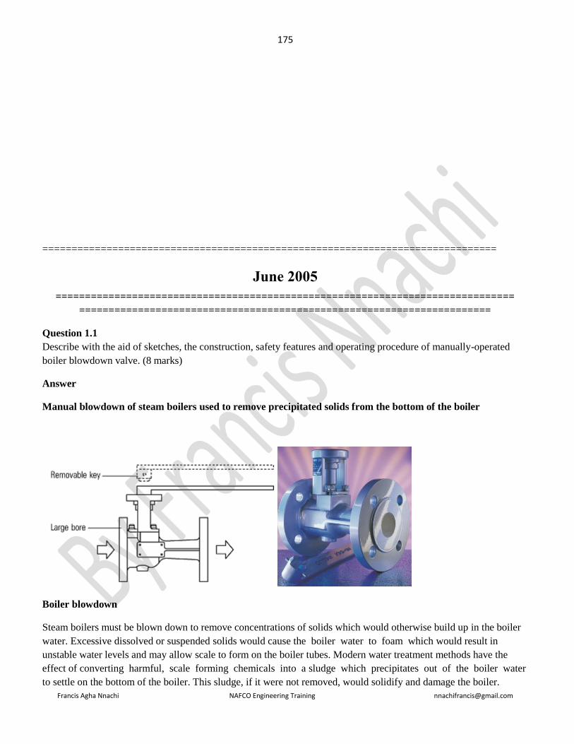
175
Francis Agha Nnachi NAFCO Engineering Training [email protected]
==============================================================================
June 2005
==============================================================================
======================================================================
Question 1.1
Describe with the aid of sketches, the construction, safety features and operating procedure of manually-operated
boiler blowdown valve. (8 marks)
Answer
Manual blowdown of steam boilers used to remove precipitated solids from the bottom of the boiler
Boiler blowdown
Steam boilers must be blown down to remove concentrations of solids which would otherwise build up in the boiler
water. Excessive dissolved or suspended solids would cause the boiler water to foam which would result in
unstable water levels and may allow scale to form on the boiler tubes. Modern water treatment methods have the
effect of converting harmful, scale forming chemicals into a sludge which precipitates out of the boiler water
to settle on the bottom of the boiler. This sludge, if it were not removed, would solidify and damage the boiler.

176
Francis Agha Nnachi NAFCO Engineering Training [email protected]
Installation
It is recommended that the valve is installed to discharge into a blowdown vessel, although the discharge
could be piped to an existing blowdown pit if necessary.
The operating key is supplied separately and cannot be removed unless the valve is closed. This safety feature is
most important where multiple boilers have a shared discharge and it is good practice (mandatory in UK and several
other countries) to have only one key in the boiler house. This feature is also useful for single boilers, where the
key may be removed after blowdown by the person responsible, thus avoiding wasteful repetitive operations by
other staff.
The positive isolation provided by the key operated valve is also a safety benefit during maintenance or repairs to
the blowdown vessel and its associated pipework.
Question 2.1
A company specializing in the repair of electrical motors wants to reduce the number of injuries. Describe how you,
as the competent person, will carry out a risk assessment in the testing bay.
Answer
walking around the repair workshop and noting things that may cause harm
talking to workers to learn from their knowledge and experience and listen to their concerns and opinions about
health and safety issues. He confirmed what training had been provided and asked that they consider particular
requirements the two young apprentices may need

177
Francis Agha Nnachi NAFCO Engineering Training [email protected]
phoning the licensed disposal contractor to discuss the arrangements for waste disposal
looking at the accident book to learn what had previously resulted in accidents or near misses.
As the hazards are being identified, then who could be harmed and how should be known. Note what has been in
place to control the risk and consider anything more is needed. Record further actions required.
Putting the risk assessment into practice, set out what actions needed to be taken. Who would do them and by when.
Place a copy of the risk assessment where all workers could see it.
The findings of the risk assessment will be discussed by the competent person and their teams of mechanics.
Review the risk assessment whenever there were any significant changes such as new work equipment, work
activities or workers.
Example risk assessment for a motor vehicle mechanical repair workshop
This example risk assessment shows a wide range of hazards that might be present in this type of small business. It
can be used as a guide to help you think through some of the hazards in your business and the steps you need to take
to control the risks. However, this is not a generic risk assessment. Every business is different. To satisfy the law you
must identify and assess the hazards your business poses, think through the controls required to provide effective
protection to people who may be affected by them, and record the significant findings from your risk assessment of
your business.

179
Francis Agha Nnachi NAFCO Engineering Training [email protected]
Question 2.2.2
State TWO ideal applications for three phase induction motors (2 marks)
Answer
Question 3.2
List and discuss the various engineering control methods used to control exposure to hazardous biological agents
(HBA) (10 marks)
Answer:
Engineering control measure for control of exposure to HBA
1. Process separation, automation or enclosure
2. The installation of local extraction ventilation systems to processes, equipment and tools for the control of
emissions of an airborne HBA
3. Separate workplaces for different process
4. Proper access control to prevent unauthorized access
5. Immediate personal/environmental disinfection
Question 4.1
Determine where a simply supported beam with a uniformly distributed load must be supported for minimum
deflection of the beam. (10 marks)
Answer
Question 4.2
180
Francis Agha Nnachi NAFCO Engineering Training [email protected]
Describe in detail the construction of a 500kVA 400V transformer, with appropriate clearly labeled and reference to
materials of construction. (10 marks)
Answer
Question 6.1
Discuss the maintenance of 6600 volt alternating current oil circuit breakers (10 marks)
Answer
1. Check the current carrying parts and arcing contacts. If the burning is severe, the contacts should be replaced
2. Check the dielectric strength of the oil, if the oil is badly discoloured, it should be changed or reconditioned.
The oil in good condition should withstand 30kV for one minute in a standard oil testing cup with 4 mm gap
between electrodes.
3. Check the insulation for possible damage. Clean the sutface and remove carbon deposits with a strong and
dry fabric
4. Check the oil level
5. Check closing and tripping mechanism
Question 7.1
Discuss and clearly distinguish between the following plastic conversion processes, with the aid of appropriate
sketches:
Blow film
Blow Moulding
Injection Moulding
In each case, list the energy supplies required to be connected to the respective machinery, as well as the types of
plastic material normally converted using that process. (12 marks)
Answer
Blow film: the blown film process is a biaxial tensile flow in which a film or tube of polymer melt is changed in
shape by means of a gas at a higher pressure than the ambient pressure, giving rise to a pressure difference across the
melt.
Blow moulding: blow moulding, as the name implies is a process where an amount of melt is expanded in a mould
using high pressure gas, sometimes mechanically assisted, to shape the melt to the mould. Once the melt has formed
the section of mould separate to remove the product from the mould.

181
Francis Agha Nnachi NAFCO Engineering Training [email protected]
Injection moulding: as the name implies, involves injecting melt into a mould using high pressure mechanical
means. Maximum cavity pressures are of the order of 150 bar.
Question 7.2
Briefly describe the periodic inspection and load testing of a 15 ton electrically-driven single hoist overhead gantry
crane (8)
Answer
In terms of the driven machinery regulations of the Occupational Health and Safety Act Regulations, user’s who
have a mobile crane, are required to examine the entire installation thoroughly, and subject it to a performance test, at
periods not exceeding 12 months. The examination and testing of the mobile crane should be carried out in
accordance with the South African Standard titled, ‘the Inspection, testing and examination of mobile cranes’, SAN
19;2004. The process for the inspection includes:
The inspection, testing and examination should be carried out by a competent person who has both the technical
knowledge and practical experience in inspection, testing and examination. Clearly, such a person should be
appointed to carry out the work
All information including rated capacity, previous alterations, maintenance repairs, renewals and operator’s
instruction must be made available to the competent person
The user must ensure that all facilities required by the competent person are made available. These could include: an
appropriate are cordoned off. The crane operator. Technician to remove covers etc.
Prior to the examination, the crane must be cleaned to ensure that no part is hidden from the competent person
The competent person must prepare an examination scheme taking into account the limiting criteria of the
manufacturer of the crane
Limiting criteria which may be specified by the crane manufacturer are listed in SANS 19: 2004, and must be
included by the competent person in his examination scheme.
Specific items which should be checked by the competent person are listed in SANS 19:2004. Twenty-eight specific
items to be checked are listed in the standard
Prior to lifting the test load, the competent person must check the entire installation to ensure that the test load can be
safely handled.
The competent person must witness a functional test to ensure that all controls are operational. The mobile crane is
loaded during the inspection to 110% of its rated capacity at all operating points, using weights which have been
calibrated in accordance with BS 7262. In the case of the specified crane, the crane should be tested with 16.5 tonnes.
The greatest stresses in the cross members will occur when the crane is loaded at the centre of the cross-beams
The efficiency of the hoist brakes must be tested
After the load test the competent person must carry out a thorough examination of the crane to ensure that no damage
was done during the load test.
182
Francis Agha Nnachi NAFCO Engineering Training [email protected]
On completion of the inspection, testing and examination, the competent person must issue a Certificate giving
details. An example of such a certificate is included in SANS 19:2004.
Should any problems be discovered by the competent person, these are given to the user in writing to rectify. If the
competent person concludes that the crane may not be operated safely, he can issue an instruction preventing the use
of the crane until repairs are carried out to his satisfaction.
Question 8.1
An instrument technician has to replace a sensor which has been mounted inside a tunnel furnace which operates at a
temperature of 450oC. The replacement of the sensor requires a maximum of two minutes. The tunnel furnace takes
four days to cool to ambient temperature, and another two days to reach operating temperature. The sensor is not
accessible without entering the furnace.
Explain in detail how you would provide for the technician’s safety with minimum interruption to production.
Answer
It is assumed that accelerated cooling and heating of the furnace structure cannot be implemented due to the
possibility of developing thermal stresses which could damage the furnace. The only other way to reduce the down
time is for the technician to replace the sensor at the highest possible temperature. This will reduce the time required
to reduce the temperature of the furnace, as well as the time to heat the furnace to its operating temperature.
Selecting the temperature at which the technician can enter the furnace will be affected by the fact that it takes two
minutes to replace the sensor.
In terms of the OHS ACT, and to morally to ensure the safety of the instrument technicians the replacement of the
sensor must be carried out in a manner which will ensure the safety of the technician.
The General Safety Regulations of the occupational Health and Safety Act provide guidelines for safe working
environments of workers, which may also be used in this case.
The following steps could be taken:
1. Working in a space with an elevated temperature is a health hazard and ensure that safe practices are
followed the guidance of a medical practitioner should be sought.
2. The maximum temperature at which the technician can work for two minutes would be identified by the
medical practitioner. This will be higher than 30oC specified in the Act.
3. The technician who will replace the sensor should be identified and should be checked out by the medical
practitioner to ensure that the technician can safely work in the furnace at the chosen elevated temperature.
4. The procedures and equipment required should be planned carefully
5. Should the technician require a ventilated suit and an airline this should be provided and its operation
checked prior to its use.

183
Francis Agha Nnachi NAFCO Engineering Training [email protected]
6. During the replacement exercise, the condition of the technician should be monitored by walkie talkie, and if
it appears that a health problem could arise, personnel should be available to remove the technician from the
furnace immediately.
7. On completion of the replacement, a report should be completed detailing the procedures, the steps taken,
and the results of the exercise.
===================================================================================
November 2004
==================================================================================
Question 1.1 (repeated June 2011 Q1.1)
With the aid of a neat, labelled sketch describe the layout and operation of a water demineralization plant to supply
boiler feedwater from raw water. (12 marks)
Answer
The terms demineralization and deionization refer to the removal of all cations and anions from water. For
demineralization, a cationic exchanger replaces hydrogen ions for cations (such as Ca2+, Mg2+, and Na+), and an
anionic exchanger replaces the anions (such as Cl−, and SO42 −) with hydroxide, thus forming water and reducing the
total dissolved salts concentration. Where high-purity water is required, mixed cation-anion resin beds are used.
De-mineralization technology is the proven process for treatment of water. A DM Water System produces mineral
free water by operating on the principles of ion exchange, Degasification, and polishing. Demineralized Water
System finds wide application in the field of steam, power, process, and cooling.

184
Francis Agha Nnachi NAFCO Engineering Training [email protected]
Operating Principle:
Raw water is passed via two small polystyrene bead filled (ion exchange resins) beds. While the cations get
exchanged with hydrogen ions in first bed, the anions are exchanged with hydroxyl ions, in the second one
Water purification process
A demineralization plant usually consists of 2 specific ionic exchangers and by a mixed bed exchanger:
Demineralization plant
1. Cationic exchanger
The first ion exchanger removes all the cationic species (e.g. Ca2+ from CaCO3 ) and exchanges them into H+ (pH
about 3-4). The H2CO3 is degassed before the second ionic exchanger. In case of cationic exchanger exhaustion, the
first ionic leakage will be sodium because of its lower charge density.
Cationic exchangers are regenerated by HCl, H2SO4 : all cationic species trapped in the resin are removed and
replaced by H + . After the completion of the regeneration, the resin is full of H + sites to be exchanged with cations
again.
Parameters:
• Sodium measurement for immediate detection of Na+ leakage (ppb level)
2. Anionic exchanger
The second ion exchanger removes all the anionic species (nitrate, chloride, sulphates, silicate) and exchanges them
into OH- . Water molecules are produced (H+ from the cationic outlet and OH- from the anionic outlet).
Conductivity is about 2 µS/cm (because of some ppb ionic species that are not completely exchanged) and the pH is
about 7.8 - 8.

185
Francis Agha Nnachi NAFCO Engineering Training [email protected]
In case of anionic exchanger exhaustion, the first leakage will be chloride because of its lower charge density.
Anionic exchangers are regenerated by NaOH, removing all anions trapped by OH - . When generation is
completed, the resin is full of OH- sites.
Parameters:
• Conductivity will clearly indicate ionic leakage if it reaches 5 - 6 µS. If conductivity reaches 5 - 6 µS, this is a clear
indication of ionic leakage.
• pH levels also indicate leaks: If pH is about 8.9 - 9.0, this indicates sodium leaks. If pH decreases, this indicates
chloride leaks.
• Therefore conductivity and pH are complementary measurements at this stage.
• Silica is sometimes monitored for diagnosing anionic bed exhaustion.
3. Mixed bed
For minimizing the effect of ionic leakage, a mixed bed is used for polishing demineralized water.
The mixed bed is a mixture of anion exchange and cationic exchange resin particles and allows high purity water to
be produced.
Conductivity should be near 0.055 µS/cm and pH equal to 7.
Parameters:
• Conductivity is measured for ensuring the final water quality (no ionic leakage, < 0.2 µS/cm)
• pH is not so often monitored at this stage but rather at the outlet of the anionic bed.
• Silica is also measured at the outlet of the mixed bed.
Other demineralization systems use reverse osmosis with one or two stages for removing 95% of the organics as well
as ionic species.
Redox or chlorine can be measured before reverse osmosis to ensure the oxidant (chlorine) removal (200 mV, 20 ppb
max) is complete. This protects the osmosis membrane.
Conductivity is also used for monitoring the efficiency of reverse osmosis upstream and downstream.
4. Storage
Demineralized water is then stored before being fed into the circuitry.
Parameters:
• Conductivity: at the outlet of the storage tank, < 1 µS/cm (CO2 influence)
5. Neutralization of effluents
Without proper treatment, the effluent from the regeneration of ionic exchanger resins does not always conform to
consents for discharge into the environment (river for example).
The addition of a neutralizing reagent is often obligatory.
pH measurement (use in the case of a 8350 probe) monitor the pH of those effluents.
When it reaches the allowable limit, the effluent can be sent to the river.
Question 2.2
Describe and clearly distinguish between touch and step potentials in relation to electrical earthing. (6 marks)
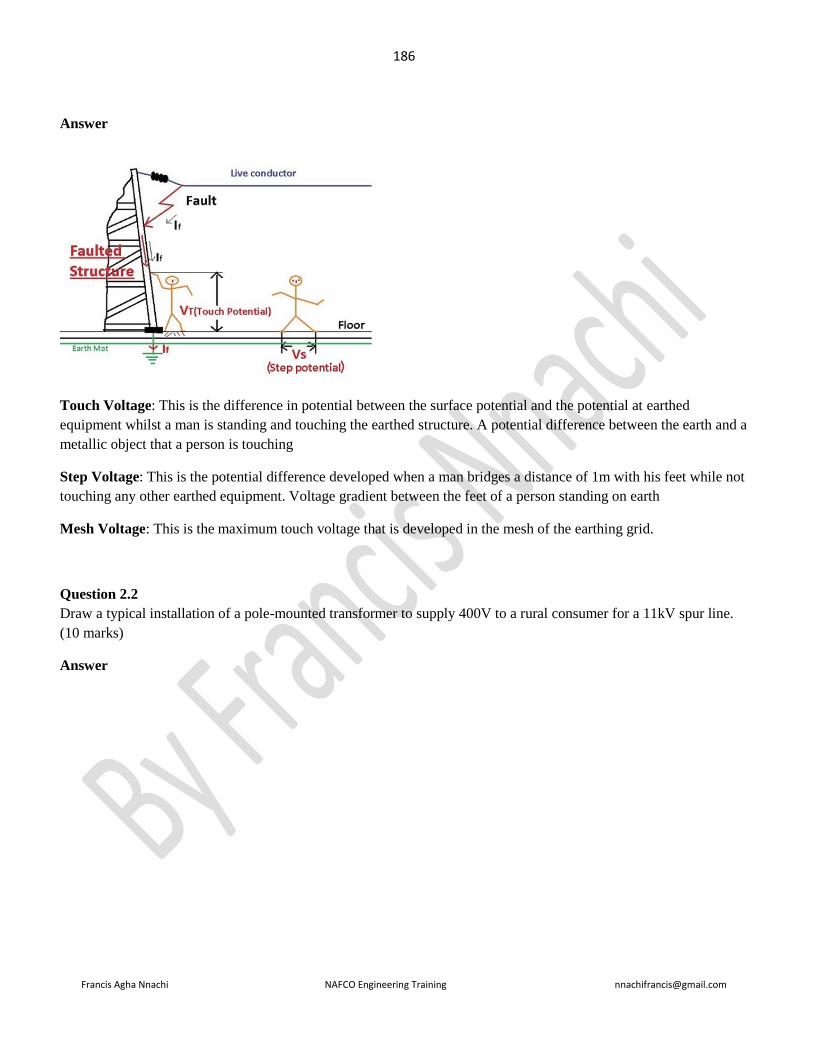
186
Francis Agha Nnachi NAFCO Engineering Training [email protected]
Answer
Touch Voltage: This is the difference in potential between the surface potential and the potential at earthed
equipment whilst a man is standing and touching the earthed structure. A potential difference between the earth and a
metallic object that a person is touching
Step Voltage: This is the potential difference developed when a man bridges a distance of 1m with his feet while not
touching any other earthed equipment. Voltage gradient between the feet of a person standing on earth
Mesh Voltage: This is the maximum touch voltage that is developed in the mesh of the earthing grid.
Question 2.2
Draw a typical installation of a pole-mounted transformer to supply 400V to a rural consumer for a 11kV spur line.
(10 marks)
Answer
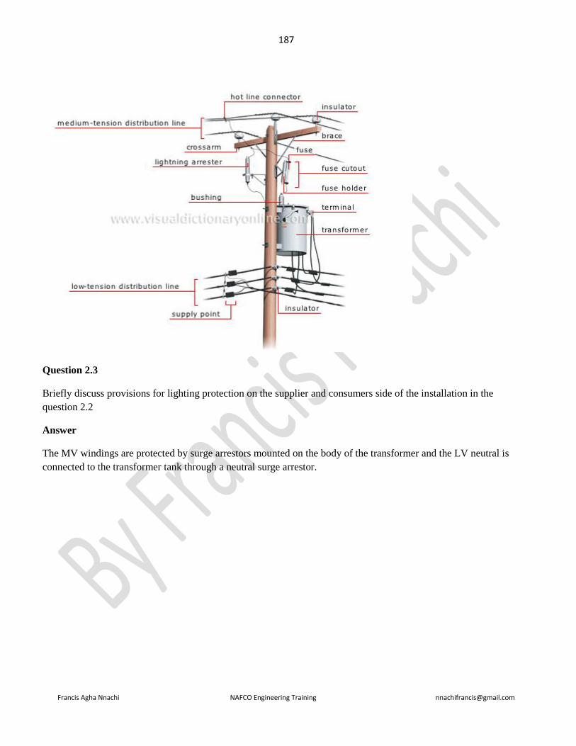
187
Francis Agha Nnachi NAFCO Engineering Training [email protected]
Question 2.3
Briefly discuss provisions for lighting protection on the supplier and consumers side of the installation in the
question 2.2
Answer
The MV windings are protected by surge arrestors mounted on the body of the transformer and the LV neutral is
connected to the transformer tank through a neutral surge arrestor.
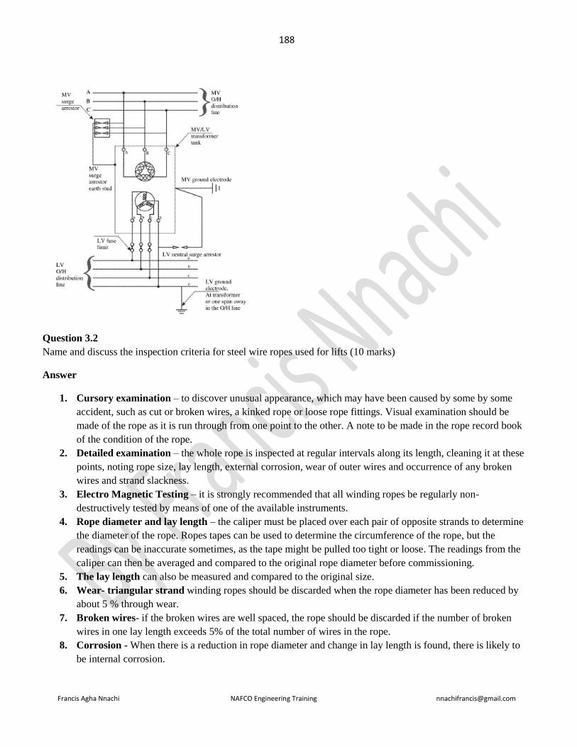
188
Francis Agha Nnachi NAFCO Engineering Training [email protected]
Question 3.2
Name and discuss the inspection criteria for steel wire ropes used for lifts (10 marks)
Answer
1. Cursory examination – to discover unusual appearance, which may have been caused by some by some
accident, such as cut or broken wires, a kinked rope or loose rope fittings. Visual examination should be
made of the rope as it is run through from one point to the other. A note to be made in the rope record book
of the condition of the rope.
2. Detailed examination – the whole rope is inspected at regular intervals along its length, cleaning it at these
points, noting rope size, lay length, external corrosion, wear of outer wires and occurrence of any broken
wires and strand slackness.
3. Electro Magnetic Testing – it is strongly recommended that all winding ropes be regularly non-
destructively tested by means of one of the available instruments.
4. Rope diameter and lay length – the caliper must be placed over each pair of opposite strands to determine
the diameter of the rope. Ropes tapes can be used to determine the circumference of the rope, but the
readings can be inaccurate sometimes, as the tape might be pulled too tight or loose. The readings from the
caliper can then be averaged and compared to the original rope diameter before commissioning.
5. The lay length can also be measured and compared to the original size.
6. Wear- triangular strand winding ropes should be discarded when the rope diameter has been reduced by
about 5 % through wear.
7. Broken wires- if the broken wires are well spaced, the rope should be discarded if the number of broken
wires in one lay length exceeds 5% of the total number of wires in the rope.
8. Corrosion - When there is a reduction in rope diameter and change in lay length is found, there is likely to
be internal corrosion.

189
Francis Agha Nnachi NAFCO Engineering Training [email protected]
Question 4.1
Draw up a list, and briefly discuss, factors to be considered when drawing up a tender specification for air
compressor and related compressed air equipment for a new factory
Answer
Question 7.2
A large standby generator is driven by a diesel engine. The engine is run every week, for between 2 and 3 minutes, as
part of maintenance schedule. The lubrificating oil has risen slightly. During a prolonged power engine outage, the
diesel engine main bearings fail catastrophically.
Explain the probable causes and corrective actions to prevent a recurrence. (7 marks)
Answer
Question 7.3
Define kinematic viscosity (3 marks)
Answer
Kinematic viscosity is the ratio of a fluid's absolute viscosity to its density, or the absolute viscosity divided by the
density. Kinematic viscosity is the most common viscosity measurement usually measured in stokes.
Viscosity of a fluid is that property which determines the amount of its resistance to a shearing force. Viscosity is
due primarily to interactions between fluid molecules.
The kinetic coefficient of viscosity is defined as kinematic coefficient 𝑣(Ƞ ∪) =𝑎𝑏𝑠𝑜𝑙𝑢𝑡𝑒 𝑉𝑖𝑠𝑐𝑜𝑠𝑖𝑡𝑦 𝜇
𝑚𝑎𝑠𝑠 𝑑𝑒𝑛𝑠𝑖𝑡𝑦 𝜌 (
𝑚2
𝑠)
Question 8.2
Describe a predictive maintenance programme, with reference to parameters to be monitored, data collection and
utilization and specialised equipment and skills required. (10 marks)
Answer

190
Francis Agha Nnachi NAFCO Engineering Training [email protected]
==============================================================================
June 2004
==============================================================================
=============================================================
Question1.1
Draw a detailed, labelled sectional sketch of a coal-fired wetback boiler, clearly indicating the fire, water and steam
spaces, the number and positions of all safety and control devices and the provision for air, feedwater, fuel, flue gas
and ash handling (12 marks)
Answer
Below is the sketch showing the cross- sectional view of a boiler
If we look at the cross section view of the boiler the following components can be identified:

191
Francis Agha Nnachi NAFCO Engineering Training [email protected]
Question 2.1
Define the SI units for the reluctance of a homogeneous section of magnetic circuit. (3 marks)
Answer
Magnetic reluctance, or magnetic resistance, is a concept used in the analysis of magnetic circuits. It is analogous
to resistance in an electrical circuit, but rather than dissipating magnetic energy it stores magnetic energy. In likeness
to the way an electric field causes an electric current to follow the path of least resistance, a magnetic field causes
magnetic flux to follow the path of least magnetic reluctance. It is a scalar, extensive quantity, akin to electrical
resistance.
Its SI derived unit is the henry (the same as the unit of inductance, although the two concepts are distinct).
Question 3
A number of organizations contribute to the management of various aspects of occupational health and safety in
South Africa. Describe and clearly distinguish between the functions and legal authority of:
- Department of labour
- Advisory council for Occupational health and safety
- National Occupational Safety association (NOSA)
- South African Bureau of Standard (SABS)
- Engineering Council of South Africa (ECSA)
- Approved Inspection Authorities
Answer
3.1 Department of labour
General Functions of Department of labour
1. Enforce social and labor legislation to protect the working class and regulate the relations between the
worker and his employers;
2. Formulate and recommend policies, plans and programs for manpower development, training, allocation, and
utilization;
3. Recommend legislation to enhance the material, social and intellectual improvement of the nation's labor
force;
4. Protect and promote the interest of every citizen desiring to work locally or overseas by securing for him the
most equitable terms and conditions of employment, and by providing social and welfare services;
5. Regulate the employment of aliens, including the enforcement of a registration or work permit system for
such aliens, as provided for by law;
6. Formulate general guidelines concerning wage income policy;
7. Recommend necessary adjustments in wage structures with the view to developing a wage system that is
consistent with national economic and social development plans;

192
Francis Agha Nnachi NAFCO Engineering Training [email protected]
8. Provide for safe, decent, humane and improved working conditions and environment for all workers,
particularly women and young workers;
9. Maintain a harmonious, equitable and stable labor relations system that is supportive of the national
economic policies and programs;
10. Uphold the right of workers and employers to organize and promote free collective bargaining as the
foundation of the labor relations system;
11. Provide and ensure the fair and expeditious settlement and disposition of labor and industrial disputes
through collective bargaining, grievance machinery, conciliation, mediation, voluntary arbitration,
compulsory arbitration as may be provided by law, and other modes that may be voluntarily agreed upon by
the parties concerned; and
12. Perform such other functions as may be provided by law
13. Advisory Council for Occupational Health and Safety
The functions of the Advisory Council are:
1. To advice the minister on matters relating to occupational safety and health or arising out of the
operational of this Act which may be brought to its attention or be referred to it, including the formulation of
a national policy on occupational safety and health
2. To make recommendations to the minister relating to programs of the Authority in Occupational
Safety and health including enforcement and the implementation of a national policy on occupational safet
and health
3. To promote public awareness of occupational safety and health
National Occupational Safety Association (NOSA)
NOSA is the leading global supplier of occupational risk management services and solutions, and is proudly the most
recognised brand in the SHEQ risk management industry.
South African Bureau of Standard (SABS)
The role of the standard division of the SAB is to develop and maintain relevant South African National Standards
and other normative documents, which are vital components of a sound technical infrastructure, as well as Quality,
Accreditation and metrology, which forms the foundation of our modern, commercial world.
Engineering Council of South Africa
In order to achieve the Act’s main focus, ECSA is empowered to perform a variety of functions, such as :
1. Setting and auditing of academic standards for purposes of registration through a process of accreditation
of engineering programmes at universities and technikons.

193
Francis Agha Nnachi NAFCO Engineering Training [email protected]
2. Setting and auditing of professional development standards through the provision of guidelines which set
out ECSA’s post-qualification requirements for registration in the four professional categories of
registration, namely Professional Engineer, Professional Engineering Technologist, Professional Certificated
Engineer and Professional Engineering Technician as well as for Specified Categories, such as Registered
Lift inspectors.
3. Prescribing requirements for Continuing Professional Development and determining the period within
which registered persons must apply for renewal of their registrations.
4. Prescribing a Code of Conduct and Codes of Practice, and enforcing such conduct through an
Investigating Committee and a Disciplinary Tribunal.
5. Identification of work of an engineering nature that should be reserved for registered persons by the
Council for the Built Environment (CBE), after consultation with the Competition Board.
6. Advising the Council for the Built Environment (CBE) and Minister of Public Works on matters
relating to the engineering profession and cognate matters
7. Recognition of professional associations, such as engineering associations, institutes, institutions and
societies.
8. Publication of a guideline tariff of fees for consulting work, in consultation with government, the
profession and industry.
9. Doing such other things as may be necessary for the proper performance of its functions in terms of the Act.
Approved Inspection Authority
1) An approved inspection authority for electrical installations may enter premises and conduct an inspection, test or
investigation only when
a) Contracted by the chief inspector or provincial director for a specific electrical installation; or
b) Requested by the user or lessor of an electrical installation to do so.
2) An approved inspection authority for electrical installations may not operate as an electrical contractor.
HOW DOES THE APPROVED ELECTRICAL INSPECTION AUTHORITY FUNCTION?
Approved Inspection Authorities may be used for inspection to determine compliance of new electrical installation
work performed by electrical contractors, an existing electrical installation or to determine the validity of an
Electrical Certificates of Compliance (COC) issued during change of ownership of properties containing electrical
installations.
No person shall sell or market an electrical installation which is subject to a safety standard unless the electrical
installation complies with that standard
Question 4.1
Describe in detail the test that is carried out to determine the efficiency of an air compressor on site (10 marks)
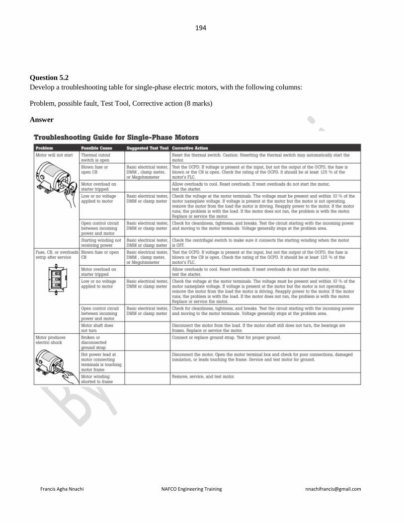
194
Francis Agha Nnachi NAFCO Engineering Training [email protected]
Question 5.2
Develop a troubleshooting table for single-phase electric motors, with the following columns:
Problem, possible fault, Test Tool, Corrective action (8 marks)
Answer
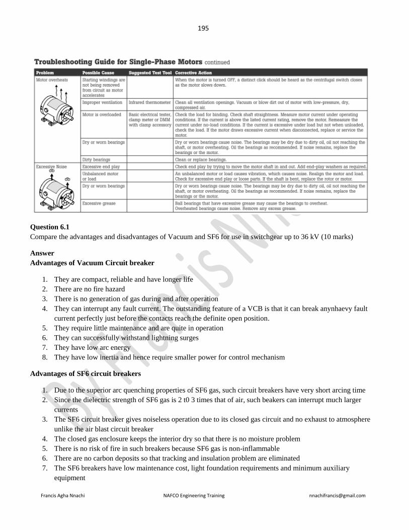
195
Francis Agha Nnachi NAFCO Engineering Training [email protected]
Question 6.1
Compare the advantages and disadvantages of Vacuum and SF6 for use in switchgear up to 36 kV (10 marks)
Answer
Advantages of Vacuum Circuit breaker
1. They are compact, reliable and have longer life
2. There are no fire hazard
3. There is no generation of gas during and after operation
4. They can interrupt any fault current. The outstanding feature of a VCB is that it can break anynhaevy fault
current perfectly just before the contacts reach the definite open position.
5. They require little maintenance and are quite in operation
6. They can successfully withstand lightning surges
7. They have low arc energy
8. They have low inertia and hence require smaller power for control mechanism
Advantages of SF6 circuit breakers
1. Due to the superior arc quenching properties of SF6 gas, such circuit breakers have very short arcing time
2. Since the dielectric strength of SF6 gas is 2 t0 3 times that of air, such beakers can interrupt much larger
currents
3. The SF6 circuit breaker gives noiseless operation due to its closed gas circuit and no exhaust to atmosphere
unlike the air blast circuit breaker
4. The closed gas enclosure keeps the interior dry so that there is no moisture problem
5. There is no risk of fire in such breakers because SF6 gas is non-inflammable
6. There are no carbon deposits so that tracking and insulation problem are eliminated
7. The SF6 breakers have low maintenance cost, light foundation requirements and minimum auxiliary
equipment

196
Francis Agha Nnachi NAFCO Engineering Training [email protected]
8. Since SF6 breakers are totally enclosed and sealed from atmosphere, they are particularly suitable where
explosion hazard exists e.g. coal mines.
Disadvantages of SF6 circuit breakers
1. Costly due to the high cost of SF6
2. Since SF6 gas has to be reconditioned after every operation of the breaker, additional equipment is required
for this purpose.
Question 7.3
Explain the term susceptance in an electrical circuit.
Answer
In electrical engineering, susceptance (B) is the imaginary part of admittance. The inverse of admittance is
impedance and the real part of admittance is conductance. In SI units, susceptance is measured in siemens.

197
Francis Agha Nnachi NAFCO Engineering Training [email protected]
===================================================================================
November 2003
=================================================================================
Question 1.1
Define and state the SI units of calorific value and briefly describe how it is determined
Answer
calorific value The gross calorific value of a substance is the number of heat units that are liberated when a unit
weight of that substance is burned in oxygen, and the residual materials are oxygen, carbon dioxide, sulphur dioxide,
nitrogen, water, and ash. The energy content of biological materials has been expressed traditionally in calories (c) or
kilocalories (C) per gram dry weight. Sometimes results are expressed more significantly in terms of ash-free dry
weight (i.e. in terms of organic constituents only). Contemporary studies of ecological energetics express results in
terms of the SI energy unit, the joule (4.182 J = 1 calorie).
Energy content in an organic matter (Calorific Value) can be measured by burning it and measuring the heat
released. This is done by placing a sample of known mass in a bomb calorimeter, a device that is completely sealed
and insulated to prevent heat loss. A thermometer is placed inside (but it can be read from the outside) and the
increase in temperature after the sample is burnt completely is measured. From this data, energy content in the
organic matter can be found out.
Question
Name and define thee unit of electrical inductance.
Answer
In electromagnetism and electronics, inductance is the ability of an inductor to store energy in a magnetic field.
Inductors generate an opposing voltage proportional to the rate of change in current in a circuit. This property also is
called self-inductance to discriminate it from mutual inductance, describing the voltage induced in one electrical
circuit by the rate of change of the electric current in another circuit.
The quantitative definition of the self inductance L of an electrical circuit in SI units (webers per ampere, known as
henries)
Question (repeated June 2002 Q2c)
An earth loop impedance test gives a reading of 1,2 ohm at private house supplied with 220V single-phase and
connected to the supplier’s earth. What is the danger presented by this situation and what can be done to correct it?
Answer
The high reading could be any number of reasons: cable size too small, cable run too long, lose or burnt connections
on live or earth, broken leg on a ring etc…
could also be a socket fed of a fused spur from a ring with the fuse raising the live resistance...
Danger

198
Francis Agha Nnachi NAFCO Engineering Training [email protected]
Normally, the fuse will blow or another circuit protection device will trip, but a situation may arise where the actual
short-circuit current in a faulty installation is of insufficient level (high loop impednace) and the protection device
would thus take too long to activate. The delay can be disastrous for life and property.
What to do
Disconnect from board and check circuit continuity and compare values.
Question
Explain why two similar alternators continue to run in synchronism after they have been paralleled.
Answer

199
Francis Agha Nnachi NAFCO Engineering Training [email protected]
==============================================================================
June 2003
==============================================================================
Question 2.1
Explain the term “discrimination” as applied to electrical reticulation. (3 marks)
Answer
Discrimination means grading of protective devices so that only the faulty circuit is disconnected from the entire
network.
The purpose of discrimination is to disconnect only the faulty circuit from the distribution network while
maintaining the upstream electrical installation active
Question 2.2
An electrically-driven pump is to be mounted on the outside of a high security enclosure, but the pump will be
started and stopped from inside the high security area. Pump maintenance will be done by artisans who will not be
given access to the inside of the security area. Describe, with the aid of suitable diagrams, the electrical control and
power circuits for the pump motor.
Answer
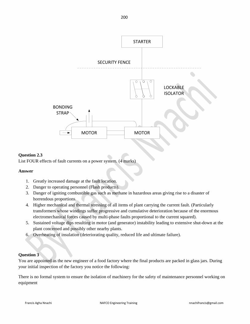
200
Francis Agha Nnachi NAFCO Engineering Training [email protected]
STARTER
MOTORMOTOR
SECURITY FENCE
LOCKABLE ISOLATOR
BONDING STRAP
Question 2.3
List FOUR effects of fault currents on a power system. (4 marks)
Answer
1. Greatly increased damage at the fault location.
2. Danger to operating personnel (Flash products).
3. Danger of igniting combustible gas such as methane in hazardous areas giving rise to a disaster of
horrendous proportions.
4. Higher mechanical and thermal stressing of all items of plant carrying the current fault. (Particularly
transformers whose windings suffer progressive and cumulative deterioration because of the enormous
electromechanical forces caused by multi-phase faults proportional to the current squared).
5. Sustained voltage dips resulting in motor (and generator) instability leading to extensive shut-down at the
plant concerned and possibly other nearby plants.
6. Overheating of insulation (deteriorating quality, reduced life and ultimate failure).
Question 3
You are appointed as the new engineer of a food factory where the final products are packed in glass jars. During
your initial inspection of the factory you notice the following:
There is no formal system to ensure the isolation of machinery for the safety of maintenance personnel working on
equipment
201
Francis Agha Nnachi NAFCO Engineering Training [email protected]
Most electrical machines are remotely started, with a resettable but not lockable emergency stop button mounted
within arm’s reach of the electric motors
Individual circuits have key-switches on the distribution boards, but the same key fits all key switches on the same
distribution board.
Most valves are of the butterfly type, with no provision for locking the valve in the closed position
There is an underground service tunnel 60m long, with pipes containing steam, hot water, cold water, carbon dioxide
gas, caustic soda, refrigeration ammonia, floor drainage and electric cables
There are numerous 20 m3 mixing tanks, with electrically driven agitators, which have to be cleaned regularly by
climbing into the tanks
Some filling machines have transparent guard panels which are interlocked so that opening the guard panels stops the
machine. However, it is possible for someone to stand between the guard panels and the moving parts of the filling
machines, and if the guard panels are closed the machine can be started.
Describe in detail all the systems you will implement in this factory in order to address the above risks to the health
or safety of employees. In each case, specify any special equipment which may need to be purchased, special
personal protective equipment required, and specialized training which must be arranged. (20 marks)
Answer
Question 4.2
Permanent magnet three-phase motors can be used in applications such as paper machines and steel rolling mills
where their accurate low speed capabilities can eliminate the need for gearboxes’. Discuss this statement, explaining
the operating principles and advantages of permanent magnet motors compared to induction motors with gearboxes.
(8 marks)
Question 5.2
Draw up an inspection checklist for 6 m high fixed ladder to ensure compliance with South African regulations (4
marks)
Answer
Question 5.3
Define and give the units for: Luminous flux, Luminous intensity. (4 marks)

202
Francis Agha Nnachi NAFCO Engineering Training [email protected]
Answer
Luminous flux - the rate of flow of light energy OR the rate of flow of light per unit of time, especially the flux of
visible light expressed in lumens.
The SI unit of luminous flux is the lumen (lm).
Luminous intensity - The luminous flux density per solid angle as measured in a given direction relative to the
emitting source OR The luminous flux per unit solid angle in a specific direction from a point source of light
The SI unit of luminous intensity is the candela (cd),
Question 6.2
Outline a maintenance plan to ensure reliability of all the electrical equipment and switchgear in a municipal
substation which receives power from 33 kV transmission lines and distributes power through 6.6 kV underground
cables. (9 marks)
Answer
Question 8.1
Explain, with the aid of vector diagram. How voltages greatly in excess of the supply voltage may occur in an
overhead transmission line. (12 marks)
Question 8.2
Why are the nominal and the nominal T-methods not suitable for the calculations for transmission lines longer than
about 300 km? (4 marks)
Answer
Question
Explain why it is necessary to apply earths to transmission lines when working on them, even though they have been
correctly isolated from the supply? (4 marks)
Answer

203
Francis Agha Nnachi NAFCO Engineering Training [email protected]
Although a transmission line is not a capacitor, it creates the same effect due to the high induced voltages over long
distances of the conductor between substations.
Like in the case of the capacitor, one can therefore say that the electrically charged conductors of a live HV line,
creates an electric field that will transfer a similar charge to an adjacent isolated line. It should be understood that this
type of induction is driven by the potential difference between the different lines and line to ground.
===================================================================================
November 2002
==================================================================================
Question 1a
Define and state the unit of ‘moment of inertia’
Answer
Moment of inertia is the name given to rotational inertia, the rotational analog of mass for linear motion. It appears in
the relationships for the dynamics of rotational motion. The moment of inertia must be specified with respect to a
chosen axis of rotation. For a point mass the moment of inertia is just the mass times the square of perpendicular
distance to the rotation axis, I = mr2. That point mass relationship becomes the basis for all other moments of inertia
since any object can be built up from a collection of point masses.
In classical mechanics, moment of inertia, also called mass moment of inertia, rotational inertia, polar moment of
inertia of mass, or the angular mass, (SI units kg·m², imperial/US units lbm ft²) is a measure of an object's resistance
to any change in its state of rotation. Moment of inertia is the inertia of a rotating body with respect to its rotation. In
consistency with the definition of regular inertia, an object that is rotating tends to remain rotating and will continue
to do so unless acted upon by an external net torque. The moment of inertia plays much the same role in rotational
dynamics as mass does in linear dynamics, describing the relationship between angular momentum and angular
velocity, torque and angular acceleration, and several other quantities. The symbols I and sometimes J are usually
used to refer to the moment of inertia or polar moment of inertia.

204
Francis Agha Nnachi NAFCO Engineering Training [email protected]
Question 1(b)
The raw water available for a boiler is pumped directly from a nearby river. Water samples from the river indicate
high levels of fluoride, silica and free oxygen. Discuss the water treatment needed for a 20 ton fire-tube boiler. (8
marks).
Answer
Flourides
Fluorides in boiler feed water also present problems in steam generation plants and need to be removed prior to use.
Fluoride can be selectively removed with activated alumina. There are many suppliers available for this media.
Silica
The presence of silica in boiler water can also lead to hard scale, which can react with calcium and magnesium to
form silicates which can severely inhibit heat transfer across the fire tubes and cause them to overheat.
The hardness is removed from the water by a process known as positive ion exchange. This process is also known as
“ion substitution”, where soft Sodium (Na+) ions are substituted or exchanged for the Calcium and magnesium
ions, as the water passes through the softener tank.
Oxygen
De-aeration is the removal of dissolved gasses, mostly oxygen and carbon dioxide, from the boiler feed water as
partial control of corrosion. The water can be mechanically de-aerated in an open heater or it can be done by
chemical treatment as stated above.
Chemicals are fed into the feed water by means of a dosing pump or by direct injection into the boiler. The chemicals
used are a scale inhibitor and also an oxygen scavenger. The oxygen scavenger de-aerates the water.
Question 1(c)
Describe the scale you would expect to find in a boiler which was fed with untreated water from the above river. (3
marks)
Answer
Scale deposits:

205
Francis Agha Nnachi NAFCO Engineering Training [email protected]
Water impurities such as calcium, magnesium and silica, commonly found in most water supplies precipitate at high
temperature and form a dense coating of material on the waterside of the boiler tubes. This layer of coating is
technically known as scale.
The key points to note here are:
The scale will act as an effective insulator and retard heat transfer
The scale will progressively narrows pipe internal diameter, roughen tube surfaces and impede proper flow.
Scale causes the tubes metal temperature to rise, which increases the flue gas temperature. In extreme cases, the
tubes fail from overheating
Scale causes fuel wastage typically up to 2% for water-tube boilers and up to 5% in fire-tube boilers
Question 2(a)
Define and state the unit of “impedance”.
Answer
Electrical impedance, or simply impedance, describes a measure of opposition to alternating current (AC).
Electrical impedance extends the concept of resistance to AC circuits, describing not only the relative amplitudes of
the voltage and current, but also the relative phases. When the circuit is driven with direct current (DC), there is no
distinction between impedance and resistance; the latter can be thought of as impedance with zero phase angle. In
general, impedance will be a complex number, with the same units as resistance, for which the SI unit is the ohm
(Ω).
Question 2(b)
Discuss the term ‘cost of ownership’ in relation to lead-acid batteries. (8 marks)
Answer
Total Cost of Ownership, usually abbreviated as TCO, is a calculation designed to help people make more informed
financial decisions. Rather than just looking at the purchase price of an object, TCO looks at the complete cost from
purchase to disposal. It adds to the initial purchase price other costs expected to be incurred during the life of the
product, such as service, repair, and insurance.
INITIAL COSTS
1. Real Estate Cost Estate Batteries
2. Battery Monitor Cost
3. Rack/Cabinet
4. Hydrogen Detection System
5. Hydrogen Evacuation System
6. Spill containment system
7. On Site Battery Installation

206
Francis Agha Nnachi NAFCO Engineering Training [email protected]
8. Monitor Installation
ONGOING COST
9. Preventative Maintenance
Question 3(a)
Describe the causes and symptoms of TWO occupational disease which affect the central nervous system.
Answer
Welders’ disease (manganism which affects the central nervous system)
Occupational exposure to welding fumes is linked to the natural chemical element manganese, a main component of
several types of welding rods that strengthens the metal as it is fused in the welding process.
The point of exposure occurs when the workers breathe the fumes released in the air as the rods are melted down.
Workers exposed to excessive amounts of welding fumes show high levels of manganese or indications of
manganese poisoning, which can lead to a disease called manganism.
Manganism Symptoms
Manganism is a condition similar to Parkinson’s disease that has potentially incapacitating physical and mental
symptoms, including:
- impaired hand-eye coordination and motor skills
- difficulty with speech or facial expressions
- tremors
- overall weakness and lethargy
Mercury poisoning, tissue damage resulting from exposure to more than trace amounts of the element mercury or
its compounds. Elemental mercury (the silver liquid familiar from thermometers) is the most common occupational
source. Exposure typically comes from inhaling mercury vapors.
Question 4(a)
Describe with the aid of neat skeleton, the equipment needed and how you would erect a 15m tall mast to be bolted
to an existing concrete base, without the use of a mobile jib crane or a helicopter. (12 marks)
Answer
Question 6(a)
Discuss the ‘lost wax’ casting process in terms of costs relative to other casting processes, materials used in the
process, machinery and plant required, skills required and typical applications. (13 marks)
Answer

207
Francis Agha Nnachi NAFCO Engineering Training [email protected]
Question 8(a)
Describe, with the aid of appropriate sketches, the construction and working principles of 5MVA rectifier suitable for
use in electroplating factory. (10 marks)
=================================================================================
JUNE 2002
=================================================================================
Question 1(a)
Explain the term maintenance and briefly discuss its relationship with the other operations in a factory
Answer
Question 2(a)
Name and define the unit of electrical inductance
Answer
Inductance is typified by the behavior of a coil of wire in resisting any change of electric current through the coil. It
is measured in henry

208
Francis Agha Nnachi NAFCO Engineering Training [email protected]
Inductance, quantity that measures the electromagnetic induction, in electricity and magnetism, common name for
three distinct phenomena.
Question 2(c) (repeated Nov 2003)
An earth loop impedance test gives a reading of 1.2 Ω at a private house supplied with 220 V single-phase electricity
and connected to the supplier’s earth. What is the danger presented by this situation and what can be done to correct
it? (5 marks)
Answer
An earth loop impedance test gives a reading of 1,2 ohm at private house supplied with 220V single-phase and
connected to the supplier’s earth. What is the danger presented by this situation and what can be done to correct it?
Answer
The high reading could be any number of reasons: cable size too small, cable run too long, lose or burnt connections
on live or earth, broken leg on a ring etc…
could also be a socket fed of a fused spur from a ring with the fuse raising the live resistance...
Danger
Normally, the fuse will blow or another circuit protection device will trip, but a situation may arise where the actual
short-circuit current in a faulty installation is of insufficient level (high loop impednace) and the protection device
would thus take too long to activate. The delay can be disastrous for life and property.
What to do
Disconnect from board and check circuit continuity and compare values.
Question 3(a)
You are employed at a new factory which produces brown paper from recycled materials. Chemicals used include
strong acid, strong alkalis, strong oxidizers and the normal chemical required for boiler feedwater treatment. The
installed electrical load is 2.5 MW and there are two boilers of 30 ton/hour steamimg capacity each. Compressed air
is used for instrumentation and for general purposes throughout the factory. There are 4 forklift trucks and 3
overhead gantry cranes, all with a lifting capacity greater than 5000 kg. the machinery has just been commissioned
by a team from the international suppliers, but the commissioning team has no knowledge of south African
legislation regarding the safe installation and operation of machinery. The factory employs 60 people, including 11 at
engineering, 31 at production, and the rest are administrative.

209
Francis Agha Nnachi NAFCO Engineering Training [email protected]
Describe the various safety management systems and legal documentation you will have to establish for this factory.
Question 4(a)
Define angular momentum (3 marks)
Answer
In physics, angular momentum, moment of momentum, or rotational momentum is a vector quantity that
represents the product of a body's rotational inertia and rotational velocity about a particular axis. The angular
momentum of a system of particles (e.g. a rigid body) is the sum of angular momenta of the individual particles. For
a rigid body rotating around an axis of symmetry (e.g. the blades of a ceiling fan), the angular momentum can be
expressed as the product of the body's moment of inertia, I, (i.e. a measure of an object's resistance to changes in its
rotation rate) and its angular velocity ω:
In this way, angular momentum is sometimes described as the rotational analog of linear momentum.
For the case of an object that is small compared with the radial distance to its axis of rotation, such as a tin can
swinging from a long string or a planet orbiting in a circle around the Sun, the angular momentum can be expressed
as its linear momentum, mv, crossed by its position from the origin, r. Thus, the angular momentum L of a particle
with respect to some point of origin is
Question 4(b)
State the functions of a receiver tank for a reciprocating air compressor (5 marks)
Answer
A receiver tank is a vessel that store air needed to meet peak demand events with minimal effect on changes
pressure. Air receiver tank serves various functions:
1. Damping pulsations caused by reciprocating compressors.
2. Supplying peak demands from stored air without needing to run an extra compressor.

210
Francis Agha Nnachi NAFCO Engineering Training [email protected]
3. Reducing load/unload or start/stop cycle frequencies to help screw compressors run more efficiently and reduce
motor starts. Most screw compressors have internal protection that prevents more than 4 to 6 starts per hour.
4. To allow better compressor control and more stable system pressures.
5. Separates moisture and oil vapor, allowing the moisture carried over from the aftercoolers to precipitate.
Question 7(b)
Compare the advantages and disadvantages of static capacitors and rotary capacitors for power factor correction in a
large factory. (6 marks)
Answer
In practice, two type of equipment are available for power factor correction:
a. Rotary Equipment: Phase advancers, synchronous motors and synchronous condensers. Where auto-synchronous
motors are employed the power factor correction may be a secondary function. A synchronous motor takes a leading
current when over-excited and, therefore behaves as a capacitor.
b. Capacitors: Power factor correction is achieved by the addition of capacitors in parallel with the connected motor
circuits and can be applied at the starter, or applied at the switchboard or distribution panel.
Capacitors connected at each starter and controlled by each starter is known as "Static Power Factor Correction"
while capacitors connected at a distribution board and controlled independently from the individual starters is known
as "Bulk Correction".
Advantages of static capacitors
1. they have low losses
2. they require little maintenance as there are no rotating parts
3. they can be easily installed as they are light and require no foundation
4. they can work under ordinary atmospheric conditions
Disadvantages
1. They have short service life ranging from 8 to 10 years
2. They are easily damaged if the voltage exceeds the rated value
3. Once the capacitors are damaged, their repair is uneconomical
Advantages of rotary capacitors
1. By varying the field excitation, the magnitude of current drawn by the motor can be changed by any amount.
This helps in achieving stepless control of power factor
2. The motor windings have high thermal stability to short circuit currents
3. The faults can be removed easily

211
Francis Agha Nnachi NAFCO Engineering Training [email protected]
Disadvantages
1. There are considerable losses in the motor
2. The maintenance cost is high
3. It produces noise
4. Except in sizes above 500 kVA, the cost is greater than that of static capacitors of the same rating
5. As a synchronous motor has no self-starting torque, therefor, an auxiliary equipment has to be provided for
this purpose
Question 8(a)
Sketch and describe the operation of a reverse pulse air filter to filter 20 m3/s of air from a mineral milling plant (6
marks)
===================================================================================
NOVEMBER 2001
==================================================================================
Question 1(a)
Among the candidates applying to be trained as boiler Attendants are the following:
A man with tunnel vision
A man who is colour-blind
A man who was born completely deaf
A man who has had one hand amputated at the wrist
State, giving reasons, which of the above candidates you would reject and how you would accommodate the others,
bearing the requirements for employment equity in mind. (8 marks)
Answer

212
Francis Agha Nnachi NAFCO Engineering Training [email protected]
Question 2(b)
Explain what is meant by a condition-based maintenance programme for large electric motors and discuss the
equipment, instruments and skills needed. (6 marks)
Answer:
Condition-based maintenance
The condition-based maintenance (CBM) strategy is also called predictive maintenance. It is an extension of the
time-based maintenance (TBM) strategy and uses nonintrusive testing techniques to assess equipment condition. It
uses planned maintenance tasks that are based on equipment’s previous operating history, and trending of the
maintenance data. It is most effective when combined with a PM program because it prioritizes Electrical preventive
maintenance (EPM) based on criticality of equipment, productivity, resources, or lessons learned from experience.
Much of the essence of effective electrical equipment preventive maintenance (PM) can be summarized by four
rules:
1. Keep it dry.
2. Keep it clean.
3. Keep it cool.
4. Keep it tight.
The electrical insulation system is the most prominent part of motors and generators that needs periodic maintenance
and testing. The insulation system of machines is subjected to varying degrees of mechanical, thermal, and electrical
stresses. The reliability of a machine depends upon the integrity of its insulation system. Therefore, a preventive
maintenance program should include an effective testing program, along with visual inspection and routine
maintenance, to evaluate the insulating system.
The insulating parts found in motors and generators consist of stator windings, field windings, winding support,
collector lead and ring, stator core, and others. The maintenance and testing program should be planned to detect and
provide data on deteriorating factors to which motors and generators are subjected. The following DC tests can be
conducted for the purposes of preventive maintenance to assess the condition of insulation systems of motors and
generators.
Insulation Resistance Test using Megohmmeter
DC Overpotential Test to assess the insulation dielectric strength
Voltage versus Leakage Current Test (Step-Voltage Test)
Leakage Current versus Time Test
Question 4(a)
Determine where a simply supported beam with a uniformly distributed load must be supported for minimum
deflection of the beam (10 marks)

213
Francis Agha Nnachi NAFCO Engineering Training [email protected]
Answer
Question 4(b)
Describe in detail, with appropriate, clearly labelled sketches, each step of how the termination of a high-voltage
electrical cable for attachment to an 11kv transformer is made. (10 marks)
Question 7(a)
Distinguish clearly between the following types of arc welding, with respect to operator skill, rate of deposition,
consumables, typical applications and limitations:
Shielded metal arc welding (SMAW)
Gas metal arc welding (GMAW)
Gas tungsten arc welding (GTAW) (14 marks)
Question 7(b) (repeated June 2008 Q5.3)
List and briefly describe THREE different non-destructive testing methods which will indicate cracks or inclusions
in a welded steel point. (6 marks)
Answer
1. Liquid penetrant testing
2. Ultrasonic testing
3. Electromagnetic testing
4. Hardness testing
5. Acoustic emission testing
6. Infrared and thermal testing
7. Magnetic resonance testing
Question 8(a)

214
Francis Agha Nnachi NAFCO Engineering Training [email protected]
An instrument technician has to climb from ground level to the top of a 30m high stack to service instrument probes
once a month. There are rungs welded to the side of the stack for access.
Explain, with the aid of suitable sketches, how you would provide for the technician’s safety. (10 marks)
==============================================================================
November 1993
==============================================================================
Question 1(a)
Briefly describe two types of steam generators for the rapid raising of steam. Give details of
Their application
Quality of the steam generated
Fuel used
Efficiency (8marks)
Answer
Rapid steam raising can be achieved by a number of means.
Coil type steam generator: in this a helical coil, or “pancake” or nest of relatively small bore, steam tubing is
exposed to the heat source. A volume of water in the tubing which is small in relation to the area through which the
heat transfer takes place is heated and undergoes a phase change to steam. This phase change can be affected at any
pressure for which the generating tubing and appurtenances is suitable. Feed water is pumped in at one end and
steam drawn off at atmospheric pressure, as in the case typical “garage steam cleaners” up to any practicable

215
Francis Agha Nnachi NAFCO Engineering Training [email protected]
pressure. The Wanson Vaporax, helical coil boiler is a good example of this type of steam generator. It is used in
light, steady load applications, such as with bakery ovens (for providing steam to glaze bread) and dry cleaning.
The reason for emphases on light, steady load application is that this type pf boiler has no practical reserve of steam
in it. A sudden, large demand for steam can cause the coil to flood and a slug of water to enter the steam range. Thus
application must be such that large, sudden demands for steam are either impossible (ideally) or highly unlikely (in
real terms0. In normal, intended use steam quality will be reasonably dry. In fact, it is possible to arrange a coil, or
pancake, or nest of tube to act as a superheater to deliver dry, or even superheated steam.
Heat sources are usually oil or gas burners, or ‘waste” heat from some other processes on the premises. The choice of
oil or gas burners is largely dictated by the need for rapid response. Wood and coal fuelled furnaces (with the
exception of pulverized coal furnaces, which are used in very large boilers) do not have rapid response times.
In coil type boiler equipped with oil or gas burners the (relatively) small volume, coupled with (relatively) large
heating surface and all but instantaneous modulation of the burners results in very rapid steam raising, provided the
generating capacity is not exceeded either during start up or operation.
Coils can be arranged to act as a combination of economiser, generating tubes and “superheater”. The water-steam
flow should be contra to the hot gas flow, with the incoming “cold” feedwater being exposed to the flue gas
immediately prior to the flue gas exiting the stack. The “superheater” should be in the hottest part of the flue gas. As
in all such installations flame impingement and overheating damage to the superheater” pass must be guarded
against. An arrangement as outlined here can be relatively economical, although, as with any boiler, high stack
temperatures mean that efficiency has been forfeited.
Calorifiers: A second type of rapid response steam generator is the calorifier. In this a relatively small heat source
can be used to apply heat to a large body of water, placed under pressure by a steam blanket, for a protracted period.
A sudden, large steam demand will reduce the pressure in the calorie vessel and cause steam to “flash-off” to meet
the demand.
The mass of steam which will “flash-off” is determined by the amount of heat “stored” in the water (liquid phase)
and the magnitude of the presuure differential which is introduced into the boiler, i.e. ms = f[δp;H]. The benefit to be
derived from such a system is that a small heat source, large enough to cope with the aggregate load, with a
conservative reserve, can also service a sudden, large demand for steam. The principle proviso is that the heat source
has both sufficient time and sufficient medium in which to store heat energy. Such a system is not “over capitalized”.
Relevant examples are provided by machines such as bottle washers and certain types of laundry equipment. Bottle
washers will in all probability not operate continuously, but will function on a one or two shift-per-day basis for a
five day week. This means that a machine is switched off every day and therefore has to be returned to line each
following day. Now, when switched on, the relatively cold machine will demand a large mass of steam, for a shortish

216
Francis Agha Nnachi NAFCO Engineering Training [email protected]
period, to bring it up to temperature. Once at temperature a considerably smaller steam generator with relatively
small heat source, comes into play for the remainder of the working shift.
This is what makes the calorifier type steam generator suitable. The large, short duration demand is met by flash
steam. The continuous, but considerable smaller steam demand is serviced by the heat source. Electrical element type
heating (such as is used in Camptel boilers) can be used to good effect.
The quality of the steam is naturally wet. Whenever “flash-off” of steam takes place, water droplets can be and are
entrained in the off take steam.
In the event of electrical element type heating efficiency can be relatively high. There is no flue gas to carry heat out
of the system. Heat losses are confined to radiation (and low level convection and conduction) losses, which, if the
user has some small measure of intelligence, are minimised by effective lagging of hot components.
Question 2(a)
Explain, using diagram where necessary, the mechanism by which transient voltages are produced when a fault on a
short line is cleared by a transmission line air circuit breaker. (6 marks)
Answer
The discussion which follows is based on the concepts of a short line in which the resistance is negligible and also
that the capacitance of the contactor bushings is negligible.
Most fault currents of reticulation systems are highly inductive. Where circuit breakers, such as bulk oil breakers,
effect arc extinction at zero current a restriking voltage which is the one transient under review here is generated. The
frequency of this voltage is a function of the LC parameters of the circuit.
Restriking Voltage Transient
Electrically a power system is an oscillatory network so that it is logical to expect that the interruption of fault
current give rise to transient, whose frequency depends on the constants of the circuit. It has been pointed out earlier
that this transient voltage is referred to as restriking voltage, which occurs immediately following arc extinction. The
arc voltage across the contacts at this instant is normally quite low, whereas the power frequency voltage in the
circuit is at or near its peak value.
Considering again a simple circuit of figure 1 in which an inductive source is cleared of a fault condition by opening
of circuit breaker S, arc extinction occurring at an instant of zero current.
The restriking voltage vc developed across the opened breaker contacts is given in Laplace form by
𝑣𝑐 =𝐸𝑚𝑎𝑥/𝑝
𝑝𝐿+1
𝑝𝑐

217
Francis Agha Nnachi NAFCO Engineering Training [email protected]
=𝐸𝑚𝑎𝑥
𝐿[
1
𝑝(𝑝2+𝜔2)]
Where 𝜔 =1
√𝐿𝐶 and 𝐸𝑚𝑎𝑥 = 𝑝𝑒𝑎𝑘 𝑣𝑎𝑙𝑢𝑒 𝑜𝑓 𝑟𝑒𝑐𝑜𝑣𝑒𝑟𝑦 𝑣𝑜𝑙𝑡𝑎𝑔𝑒. Transforming back into a time function
𝑣𝑐 = 𝐸𝑚𝑎𝑥(1 − 𝑐𝑜𝑠𝜔𝑡)
The maximum value of restriking voltage 𝑣𝑐 is 2𝐸𝑚𝑎𝑥 and occurs at 𝑡 = 𝜋/𝜔 or equal to 𝜋√𝐿𝐶. The oscillatory
transient voltage has a frequency of 1/2𝜋√𝐿𝐶 Hertz.
Question 3
Persons involved in the design of plant have a responsibility to ensure that as far as practicable the plant they design
is safe and does not present a hazard to either the public, employees, the environment, property or production.
In accordance with the above statement describe how you will go about conducting the following in a furniture
factory:
Safety reviews
Safety audits
Hazard (risk) analysis (20 marks)
Answer
The problem is discussed in terms of
Three areas of influence
Three time bases
Two distinct forms of management, as used by all larger concerns
Before the detailed activities of a furniture factory are discussed the typical characteristics of a furniture factory, and
scope of these are defined. This will establish the three principal zones, or areas, of influence which the management
has to control.
The normal construction material used in such factories is wood (with, of course, various upholstery and finishing
materials. This, naturally, means that the whole spectrum of wood working machinery can be expected to be used,
with all the dangers attendant on circular saws, spindle moulders, morticing machines, stapling guns, etc, etc.

218
Francis Agha Nnachi NAFCO Engineering Training [email protected]
In all probability there will be varnish or lacquer spraying in a section of the finishing department. Obviously wood,
especially small pieces and waste is highly flammable. Furthermore, cutting, planning and moulding of wood
produces large output noise.
Although the question does not read that way management involvement has to start with harzard and risk analysis.
The activities of the factory can pose a threat to
The welfare of the employees, (and ownwres, if on site) in the form of
- Laceration or amputation injuries caused by process machinery
- Auditory damage caused by exposure to high, protracted noise sources
- Respiratory tract and organ damage as a result inhalation of dust vaour 9from the finshing department)
- Burn injuries in the event of fire breaking out on the premises
- Possible dust or vapour explosions causing injury.
The public in the form of
- Fire, spreading from the factory to the surrounds
- Explosion damage, should there be a dust or vapour explosion
- High noise output impinging on neighboring premises
- Wood waste settling out on the surrounding premises
(The latter two are perhaps more of nuisance that a three to life and limb)
The environment in the form of
- Fire damage, spreading from a fire on the premises to the surroundings
- Wood waste disrupting local fauna and flaura, if this is relevant
- High noise levels disrupting the local fauna and flora
The identification of these (and such other hazards as are relevant) is, naturally, the initial step in managing such
venture. Obviously then, the identification activities constitute part of the first phase also has tp encompass definition
of hazards and risks, declaration of the attitude toward and policy of management with regards to such risks and
detail analysis of defined risks and hazards, it can be convincingly argued that definition and analysis, while very
closely allied, in this regard, are not synonymous.
Once the first phase has been concluded and there are a declaration of intent on the part of management and a
comprehensive analysis of defined risks and hazards to hand the second phase can be commenced. The second phase
is to plan, develop and institute potentially effective and satisfactory means of controlling each of the defined
hazards. To be effective and satisfactory control measures have to regulate hazards and risks in such a way that the
physical dangers are reduced to an acceptable level while the operators of the company remain financially and
economically viable.
It is important to stress here that no activity can be perfectly safe and absolutely free of risk or hazard. Communities
entertain and impose, morally and legally, acceptable levels of risk and hazard, which are both dynamic and relevant

219
Francis Agha Nnachi NAFCO Engineering Training [email protected]
to specific, particular manifestations of human psyche. Thus, the actions of management are not based on absolutes,
but are always relative to environment, surroundings, time and financial considerations and constraints.
Rather obviously, the third phase is the utilization, adaptation, modification and maintenance of each of the control
measures instituted at the conclusion of phase two, for these activities to be meaningful and managed, management
has to specify structure, format, yardstick, communication measures and channels, responsibilities involved in each
activity relating to the third phase.
In the introduction mention was made of two distinct and discrete forms of management which are relevant to an
undertaking of this nature. Reference is made to management in the forms of service function and line function.
Phases one, two and three involve an intimate interweaving of these two.
Senior management, of necessity, must initiate phase one. Deliberations will involve production, maintenance,
finance, personnel, etc, departments because of the scope and ramification of phase one, it is entirely possible that
senior management will appoint outside consultants and experts to assist in dispatching phase one. All in all the
management process will be centered on service functions with house and outside contributors performing a service
to senior management.
Phase two, which starts with planning and developing of control measures initially also entails service function
management, with contributions made by various parties appointed specifically for that purpose. However, the
second portion of phase two, which involves implementation of control measures, is based on line management
functions.
The proposed control measures that are accepted by senior management become company policy and devolve onto
the various line functionaries. To have any value at all, each control measure must be given the authority which is
required to impose and operate that control measure, have a clear, effective line communication, upward and
downward from him, wherewith to function with regard to the measure, and be held accountable for the performance
of that measure.
The third phase commences on a basis of line function management. Persons to whom responsibility for control
measures has been delegated may delegate specific portions ro functions of such measures to subordinates in their
line of responsibility. (this does not absolve them of responsibility).
At this juncture the safety reviews, referred to earlier as the yardstick enter the picture. These reviews will monitor
the performance of the control measures in question and report in a meaningful manner. As the act is instructed at the
present moment employers are required to appoint safety representatives. These will be privy to such safety reviews.
Essentially the review will be conducted by someone associated with the line responsibility of that measure.
On the other hand, safety audits, will again introduce service function management. By definition an audit, per se, is
an official examination of records. So as to be (relatively) free of conflict of or vested interests audits are performed
by persons outside the line of responsibility of that actvility. Thus it is a service function again. The mandatory safety
committee is privy to these audits, which are there to establish the accuracy of the various safety reviews.
The Act demands the appointment of sfety representatives and committees. These must be in place, there is no
option. An employer is at liberty, of course, to exceed these requirements. There is ne reson why phase three cannot
220
Francis Agha Nnachi NAFCO Engineering Training [email protected]
be structured to be effective and meaningful, by the simple expedient of the employer delegating responsibility to
competent persons in strategic positions
Question 4(a)
Describe the major cause of explosions in screw type (Lysholm) air compressors. Detail control measures to prevent
such explosions (10 marks)
Answer
In these machines, only the male rotor is driven. Oil is injected into the working space, to both remove heat from the
machine and also lubricate the rotors as the male rotor bears against and drives the female rotor. The oil is removed
from the machine, passed through an oil filter and cooler to extract the heat from it, and then re-injected into the
working space. The oil is thus a medium for transporting the thermal energy released during compression.
The temperature rise must be limited to below 100oC. beyond that yemperature the oil tends to carbonize and creates
an explosion danager. In the drilling application two stage machines are used. The frist stage has a delivery pressure
of 800 kpa. Oil is injected to this stage to limit the delivery temperature to between 80 and 85 oC. the second stage
raises the delivery pressure to 2.2 Mpa. The volume of injected oil carried over from the first stage, there is usually
no oil injection into the second stage, is sufficient to limit the temperature rise in the second stage to be between 2
and 3 oC. Thus the discharge air should be at temperature between 82 and 88 oC. In the second stage the pressure
ratio is only 2.75:1
Oil is extracted by means of primary and secondary separators. The primary separators have large contact chambers
while the secondaries are glass fibre cartridges. Oil inclusion in the air after passing through these is usually less than
30 ppm. If needs be a cooler and activated charcoal filter can reduce the oil content further.
These machines generally have roller bearings to contend with the radial loads and four-point ball bearings to deal
with the axial loads. A balancing drum is subjected to the full oil pressure and counteracts some 40% of the
compressor thrust. Twenty thousand hours of operation between major overhauls is the norm.
To limit the danger of explosion attention must be paid to
- Operating temperature
- Type of oil injected into the machine
- Volume of oil injected into the machine
- Quality of oil, with respect to carbonization, injected into the machine
- Condition of rotor bearings
Power demand of the compressor, as an increased demand for the same delivery means a loss of efficiency and
greater release of thermal energy into the machine

221
Francis Agha Nnachi NAFCO Engineering Training [email protected]
===============================================================================
June 1993
================================================================================
Question 1 (repeated June 2012 Q1.1, Nov 2009 Q1.1)
In view of increasing fuel prices, it has become of prime importance toneconomise on the use of fuel and to practice
energy conservation. Your boiler comprises three horizontal fire tube boilers of which two are generally on line to
meet a load of 15t/h.
Your process plant runs 24 hours/day. 7 days per week and you have good and adequate instrumentation. Assuming
that your unburnt losses are minimised (zero in the event of oil or gas firing) and that your boiler feed water is
supplied from a dearator at 105 oC and the boiler exit flue gas temperature is 250oC:
What is the biggest single loss factor affecting your boiler efficiency? (10 marks)
How would you propose improving your boiler efficiency by about 4% e.g. from 76% to 80% in the event of coal
firing or from 80% to 84% in the event of oil or gas firing? (10 marks)

222
Francis Agha Nnachi NAFCO Engineering Training [email protected]
Answer
(a) The question does not indicate if the boilers are equipped with economisers or combustion air heaters. It does,
however, specify that the boilers are fire-tube type. In package form these boilers are generally, not supplied with
either economisers or combustion air heaters. Consequently this solution approaches the problem from that angle.
There are numerous, unavoidable ways in which boilers on range loose heat. Radiation through the shell and gas
passage covers is reduced by lagging, but is nevertheless present. Every time boiler water is dumped during the
essential, twice or thrice daily blowdown periods hot boiler water is discharged. Be that as it may, the major loss of
more or less usable heat is in the hot flue gas, which is exhausted after passing through the two or three heat transfer
passages (passes) in the boiler.
In oil and gas fired boilers combustion air masses can be controlled to a high degree of accuracy and precision. This
means that the mass of flue gas is kept to a practicable minimum and thus the quantity of heat energy contained in
the flue gas, for a given temperature, is minimised. Thus losses are kept to a minimum, as far as mass of flue gas is
concerned. In coal fired boilers there has to be an excess of combustion air, as the combustion of coal is a two stage
process; 2C + O2 2CO and then, with excess (secondary) air, 2CO + O2 2CO2. More air than the stoichlometric
mass will have to be supplied to ensure complete combustion and there will thus be a greater mass of flue gas than
the theoretical ideal. As a consequence of this more heat energy exists in the flue gas of a coal fired boiler (for an
equal gas temperature) than will be lost from an equivalent oil or gas fired boiler.
Obviously, it is this supply of heat in the flue gas which has to be the target in endeavours to improve boiler
efficiency. The proven methods of achieving this are the aforementioned economiser and combustion air heater (also
known as a pre-heater). Tube passes are arranged in the flue gas, after it exists the last set of gas passeges in the
boiler. Feedwater pumped through these passes, prior to entry to the water space of the boiler, which is effectively an
evaporator, extracts heat energy from the flue gas and in so doing the enthalpy of the water is increased (and the
temperature of the flue gas reduced). This means that more of the heat energy applied to the boiler water, in the
evaporator, can be used to provide latent heat of evaporations, i.e. produce more steam.
A heat exchanger is situated in the flue gas, down stream of the economiser and the combustion air is blown through
it, by the forced draught (FD) on the way to the furnace. This air extracts heat energy from the flue gas. This means
that heat energy released in the combustion of the fuel can raise the temperature of the products of combustion above
that reached with unheated combustion air. The effect of this is to compensate for the temperature rise in the water
entering the evaporator, as a result of the economiser effect, and drive more heat into the boiler water, per kg of flue
gas. (heat transfer is a function of a temperature differential – the greater the differential, the greater the heat transfer.
The economiser is situated before the air heater for reasons of temperature differentials, which are essential to the
flow of heat energy. Feed water, which is normally hot (although not as that quoted in the question, as at 105 oC the
dearator has to be pressurized, which is an inordinary stupid thing to do, because if the object is to get gases out of
solution, the pressure in the dearator must be reduced), say 80 oC, is passed through the flue gas which is at say 250
oC, to experience an initial temperature differential of some 130 oC. Combustion air, at perhaps 25 oC, is passed
through the flue gas, down stream of the economiser, where the flue gas temperature is say 220 oC, to be exposed to
an initial temperature differential of some 195 oC.
223
Francis Agha Nnachi NAFCO Engineering Training [email protected]
At the end of the day, some but by no means all, of the heat in the flue gas is recovered, placed ibto the steam and
made available for use. The fact that not all the heat is recovered is a result of the relatively low temperature of the
flue gas, after passing through the quoted recovery devices. The remaining temperature differential is too small to be
used in a practicable manner.
(b) For the purpose of illustration a 7.5 ton per hour, fire tube, “John Thompson” type of boiler has been considered.
The operating pressure is 950 kPa. A dryness fraction of 0.98 is used. Reference to steam tables indicates a working
temperature of 182 oC (1050 kPa abs). The mass flow of the steam per second, 𝑠 = 2.0833 𝑘𝑔/𝑠. Fuel consumed
per second, 𝑓 = 0.25 𝑘𝑔/𝑠 (approximately) of coal with a calorific value of 25.2 Mj/kg. For a fuel to combustion
air ratio of 1:20 tha mass of air required per second, 𝑎 = (20 𝑥 0, 25) = 5 𝑘𝑔. The mass of flue gas generated per
second, for the production of 2.08 kg/s of steam, 𝑔 = (0.25 + 5) = 5.25 𝑘𝑔/𝑠. A workable value for the specific
heat of flue gas is 𝐶𝑝 = 1.086𝑘𝐽/𝑘𝑔𝑘
If the boiler efficiency is to be 80%, a heat balance check shows that to generate 2,0833 kg of 98 % dry steam, from
feed water, from 5987.5 kJ of heat supplied in the fuel. This means 2376 kg of fuel and 4.75 kg of air.
Installation of a purpose built economiser, in the flue where the gas tempersture is 250 oC, for an efficiency of 80%,
could extract sufficient heat from the gas to reduce its tempersture say 241 oC. The heat balance here is
∆𝑇𝑔. 𝑔. 𝐶𝑝 = ∆𝑇𝑤𝑤𝐶𝑤
Where the subscript w is for feed water. 𝑤 = 𝑠
Therefore, (250 − 241) × 4.9896 × 1.086 = (𝑇𝑤 − 105) × 2.0833 × 4.186
𝑇𝑤 =9 × 4.9896 × 1.086
2.0833 × 4.186+ 105 = 110.6 𝑜𝐶
The air heater is situated in the flue gas where the gas temperature is 241 oC. A viable temperature for the
combustion air, after the pre-heater, is 60 oC. Ambient air temperature is taken as 20 oC. For this exercise the heat
balance is
∆𝑇𝑎 . . 𝐶𝑎 = ∆𝑇𝑔𝑔𝐶𝑔
Therefore, (60 − 20) × 4.9896 × 1.005 = (241 − 𝑇𝑔) × 4.9896 × 1.086
Therefore,
37 = 241 − 𝑇𝑔 ;
𝑇𝑔 = 204 𝑜𝐶
Heat energy content of the flue gas is 4.9896 × 204 × 1.086 = 1105.4 𝑘𝐽
The heat transferred by and entrained in the component parts of the boiler is shown on the accompanying sketches. In
the first instance the boiler is shown only an evaporator and the heat balance devolves to an efficiency of 76 %. In
the second instance the effects of both an economiser and a preheater are shown, with a resultant efficiency of 80 %.
224
Francis Agha Nnachi NAFCO Engineering Training [email protected]
As stated earlier, the temperature of the gas exiting the furnace is a number of degrees higher with an air heater tha
without it. Thus the heat energy transferred to the boiler water in the evaporator, per kg of flue gas, is increased. In
fact the increase in gas temperatue is given by
∆𝑇 =4.75×1.005×(60−20)
4.9896×1.086= 35.25 𝑜𝐶 higher at exit from the furnace than the temperature when no air heater is used.
Diagram……..
Question 3
A hazard is any existing or potential condition in the workplace which, by itself or by interacting with other variables
can result in the unwanted effects of deaths, injuries, property damage, and other losses.
Briefly describe
a). a potentially hazardous condition in your work situation and detail your evaluation of the various elements. (10
marks)
b). the hazard which may result if gasoline or any other flammable substance comes into contact with sulphuric acid
(10 marks)
Answer
The sky is very, very nearly the limit in a question of this nature. Candidates are cautioned to apply strict time
control in dealing with this type of question. No more than 18 minutes should be used. The author presents the
following scenario.
A company has a large, centrally located boiler house and various, dispersed plants which use steam. The boiler plant
feeds a single range, which branches outside the boiler house, and runs continuously, so that there is always steam
fed into the range. Not all the plants which use steam operate continuously; some operate on a single shift day.
Isolating valves are placed in the branches of the steam main, some distance away from the boiler house.
Diagram …….
Operating practice is to isolate the steam supply to the plant which works a single shift day, at the end of each shift,
by closing isolating valve 1. At 05:00 on the morning of each working day the boiler operators that are on shift open
isolating valve 1 to admit steam to tha plant which operates a single shift day. The steam main up to isolating valve
1, although lagged, is exposed to the atmosphere for some 30 m before isolating valve 1.

225
Francis Agha Nnachi NAFCO Engineering Training [email protected]
The boiler operators report that the pedestals on the bonnet of isolating vave 1, which support the spindle nut of the
valve, have “broken” and the valve cannot be closed. Investigation reveals that the pedestals have broken in tension.
A detailed enquiry follows and boiler operator admits that when he opened the valve that morning there was a violent
shock in the line and impacts the valve.
This means that the steam which had condensed in the steam line during the night had formed a slug of water which
when the isolating valve was opened, entered the valve at very velocity. The geometric shape of the interior of the
valve caused this momentum to be destroyed in a brief internal and this rapid change of momentum caused hydraulic
shock in the valve. An impact force, sufficient to break the pedestals, was placed under the poppet of the valve.
Obviously the steam trapping on the line immediately before the isolating valve was either inoperative or inadequate
and permitted the slug of water to accumulate in the steam line. Plant damage is overt; the valve is broken,
production will have to be lost because the steam supply to the main will have to be stopped while repairs are
effected and until such as the repairs are complete the single shift plant cannot be isolated. The covert danger here is
that a slug of water in the steam line can rupture the valve body, when the valve is opened. This means that the
person that operates the valve will, in all probability, be very severely burnt and that all steam supply to the factory
will be lost as there is rapid and massive loss of steam to the atmosphere.
To resolve this problem it is necessary to address the shortcomings in both the design and operation of the system.
All branches and the respective isolating valves should be placed as close to the boiler house as is practicable, so as
to reduce the length of steam line in which steam condenses. There has to be adequate provision of steam trapping,
upstream of each isolating valve , so that condensate can be automatically discharged.
There must be frequent, routine, meaningful checks of each steam trap to establish that it is operating successfully.
Naturally, there must be a mechanism for reporting any malfunction that is found and also a corrective action
programme that comes into operation after such a report is filed.
Operators have to be trained to open valves extremely slowly in applications such as these. If there is a slug of water
in the line it does not gather great momentum and moves through the valve slowly, without doing damage.
Operating practices have to be checked, from time to time, to ensure that there is adherence to laid down procedures.
(b) The question nominates the mixture of hydrocarbon, petrol, C8H18 isomers with sulphuric acid, H2SO4.
In this way hydrogen sulphide, H2S, water, H2O and carbon, C can be formed. Hydrogen sulphide is an evil
smelling, toxic and flammable gas. The dangers to persons are obvious; poisoning and, if there is an explosive
mixture with air and an ignition source, a gas explosion, both with immediate effect.
The carbon is released as a particular precipitate, in the form of sludge. This coats and blocks pipes, valves, filters,
traps, drains, etc, etc, and thereby produces another hazard, in the medium term.
The free water can initiate corrosive damage, and thereby produce yet another manifestation of hazard, albeit that
this one is longer term.
As an over simplification, 9H2SO4 + 4C8H18 9H2S + 36H2O + 32C

226
Francis Agha Nnachi NAFCO Engineering Training [email protected]
Question 8 (b)
Describe how you would evacuate the refrigerant from a large refrigeration unit and how you would pressure test the
vessel.
Answer
The inlet to the condenser is closed and the compressor is run sp as to evacuate the refrigerant from the klines and
pumps it into a liquid receiver provided for the purpose. When the plant is evacuated the outlet from the condenser
and the inlet to the liquid receiver are closed.
The condenser unit can now be disconnected from the plant. Pressure lines can be connected to the condenser.
Depending on ther type of condenser it can be either hydraulically of gas tested, with nitrogen. If it is hydraulically
tested the test pressure can be 1.25 times the maximum operating pressure. If it is gas tested the pressure will be 1.1
times the maximum operating pressure and measures have to contain blast damage in the event of rupture while
under gas pressure.
Before any tests are done the compressor motor must be effectively isolated and locked out. The compressor starts
automatically, in normal operation and this must be prevented.
Once the test is completed the condenser will be evacuated and at the completion of this the refrigerant will be bled
back into it and the system progressively, prior to recommissioning.
===============================================================================
November 1992
=============================================================================
Question 1(a)
Explain the benefits and particular applications of steel ropes of
Lang’s lay
Common lay
Non-spin lay types
(3marks)

227
Francis Agha Nnachi NAFCO Engineering Training [email protected]
Answer
There are two generally ways of laying up rope, namely ORDINARY (regular or common) lay and LANG’S lay.
LANG’S LAY
A rope is a combination of strands which are formed round a core. When the direction of lay of the strand matches
that of the rope tha lay is termed Lang’e Lay or in Europe, sometimes,
parallel lay.
Figure below shows lang’s lay rope in which both the wires in the
strands and the strands in the rope are laid in the same direction . Rope
made Lang’s lay tends to wear more evenly than common lay rope,
owing to the rotational movement of the rope when at work and since
the wear is spread over a longer length of wire, the rope does not
fatique when it becomes worn. Lang’s lay ropes are slightly more
flexible than common lay ropes of similar size and construction and their resistance to bending fatigue is better. They
are extensively used for winding and haulage duty, but no universal rules can be given regarding their application
other than that their use is limited as compared with the common lay rope.
A Lang’s rope should not under any circumstances be used for hoisting vertically without guides, as in the case of
cranes or similar duties where the load is suspended from a free end and the rope is able to rotate.
Triangular and ribbon strand ropes are almost invariably made Lang’s lay as these strand formations are extremely
prone to fatigue when made common lay.
ii). COMMON LAY
Ordinary or common lay rope is the most usual configuration. The rope
is laid up in the opposite direction to the strands, so for example the rope
will be right hand and the strands left hand. This arrangement gives a
most stable rope which is able to operate with one end free without

228
Francis Agha Nnachi NAFCO Engineering Training [email protected]
distortion. Of course the rope end will rotate with any change in load if it is free to do so. Figure below illustrates an
ordinary lay rope.
Ordinary lay ropes can be used in most applications but they do have the disadvantage of slightly inferior fatique
properties compared with Lang’s lay ropes.
In other words, common lay rope the wires of the strands are laid in one direction and the strains are laid into the
rope in the opposite direction as shown in figure. Ropes laid up in this manner are suitable for all general work.
iii). Non-Spin Lay type
When tension is applied to a single layer rope it tends to untwist. When the end of the rope is not constrained and any
amount of spin is undesirable, non-spin is used.
This type of rope consists of a conventional single layer rope over which an additional layer (or layers) of strands is
laid in the opposite direction. Due to its complexity, this type of rope is not as robust as conventional rope and
requires more careful handling.
Question 2(a)
Explain the benefits of applying power factor correction equipment to electrical installations in hazardous locations.
(5 marks)
Answer
To answer this question, the candidate has to investigate the term “hazardous area” and then relate the significance of
this to the effect of power factor correction on electrical equipment.
In the sense implied here “hazardous area” means a locality or environment in which there is an explosive mixture of
air and either gas or vapour or dust, or some combination of these. In this context electrical equipment should be
flame or explosive proof, to prevent ignition of the mixture as a result of flashing, sparking or arcing. The purpose of
the flame or explosion proof equipment is to prevent the release of energy into the mixture. This equipment limits the
energy which leaks away from the spark or arc to the surrounding atmosphere.
The energy level of a spark or arc is a function of the current rushing into the spark or arc. The greater the current,
the greater the energy. The purpose of the power factor correction is to reduce the current flowing in a circuit , by
removing most , if not all, of the wattles, or reactive, power. Thus, in a pwer factor corrected circuit the current levels
are lower and the flame or explosion proof equipment has to deal with lower energy levels in the evnt of sparking or
arcing.
A further benefit of power factor correction is that, by reducing current levels flowing through windings and
conductors, the heat generated in the windings or conductor, and consequently the temperature of the windings or
conductor, is reduced. The heat generated per second, Q is a function of I2R. thus in the event of a circuit having a
power factor of 0.8 the current level in it is 1.25 time the ideal , I, and the heat released per second is 1.5625 x I2R,
i.e. 56% greater. Temperature of some objects reaches or exceeds the “flash point” ignition can and does result. The
effect of the power factor correction is to minimised, within operating limits, the temperature rewached by windings

229
Francis Agha Nnachi NAFCO Engineering Training [email protected]
and conductors and, as a result, limit the risk of some current carrying component reaching the flash point of the
mixture comprising the atmosphere.
Question 3(b)
Fires in buildings and mines are found to be started by electrical cable and cable joint faults. Explain the checks he
would conduct so as to eliminate this cause of fires. (10 marks)
Answer
In an era of ever more user friendly instruments there are hand held devices available whereby “hotspots”, even those
enclosed in distribution boards, can be found with ease and convenience. Let us return to basic; why will a hotspot
develop? Heat generated per second (joules/s = watts) is a function of I2R, where I is current flowing in amps and R
is the resistance through which the current is flowing in ohms. If the resistance, R, increases at some point in the
circuit, more heat energy is released at that point, temperature there rises and hotspot is created.
Why will the resistance increase? The common causes are loose, or carbonized, connections and contacts.
These facts point the infra-red sensing instrument in the hands of the responsible factory engineer at terminals, wire
taps, cable joints, contactors and switch gear.
Question 4(a)
The efficiency of reciprocating air compressors is usually calculated on an isothermal basis while the efficiency of
rotary compressors is evaluated on an isentropic basis. Explain this difference. (5 marks)
Answer
Question 6(a)
Explain and illustrate with sketches a method of reclaiming energy from
(a)(i) the constant supply of wood shavings and lumber waste produced from the manufacture of furniture
Or
(ii) a mine which has a methane gas
(10 marks)
(b)A dumper used for road haulage has a failsafe, spring applied, hydraulically released braking system. Sketch a
suitable hydraulic circuit. (10 marks)
Answer

230
Francis Agha Nnachi NAFCO Engineering Training [email protected]
(a)(i) there are two means of recovering energy from wood. Both entail converting the chemical energy in the wood
to heat energy and then applying the heat energy to some process. The simpler method is to burn the wood waste in a
so-called “Dutch oven” attached to a steam boiler. The heat energy released by the combustion of the wood is
transferred to the boiler water and in that way steam is generated. The steam can then transfer the energy to whatever
process requires it.
The Dutch oven is reasonably facile and both water tube and fire tube boilers can operate successfully with such a
device. It is usually a separate furnace structure which communicates with gas passage of the boiler. One of the
reasons for this is that wood waste, especially of the type generated by a furniture factory, can and does contain
awkward and irregularly shaped pieces of wood. This creates a problem with automatic stoking. Thus a separate
furnace is used and it is very frequently hand stoked.
An alternative method is to extract flammable gas from the wood. The process is called gasification. The wood is
placed in a retort and heated, usually by controlled combustion of some of the wood itself, and the volatile
components are driven off, captured in the top of retort, led off, scrubbed to some extent to remove impurities, ash,
etc and then stored for use. This provides a clean burning fuel source that can be used for heat generation and can
even be used to fuel internal combustion engines. The process leaves a residue of charcoal, which can be used either
as a fuel or for chemical purposes. One difficulty with this gasification method is that the gas is captured at low
pressure and therefore occupies a large volume and, as such, represents a storage of low energy density. It can be
compressed, but this entails compressor plant and pressure vessels, which tends to make the process capital intensive.
(ii) Methane gas in mines is the scourge of miners as it is extremely dangerous. By the cruel ironies of life it is also
an excellent fuel. Money has to be spent by any mine which can have a methane problem so as to control it. If the
methane can be tapped and used it can redeem the money spent on the control measures. The component parts of
such a scheme would have to encompass
- Detection equipment
- Extraction equipment
- Means of transporting the gas (pipe lines, et all)
- Means of purifying the gas (scrubbing plant)
- Storage facilities, possibly involving compressor plant
- Means of obtaining value form the gas by either
- Burning it (in boilers and engines) to provide energy which would cost money if obtained from some
other source or
- Selling it for reward
The recovery plant, as distinct from a disposal facility, will have an annual overhead, capital expense and also an
annual operating expense which could be based on kilograms of gas recovered. The “income’ generated by the gas
plant could be based on joules produced costed at the rate of the alternate energy source. These are the constituents
of the classical break-even graph and management would have to initially make a projection along these lines to test
the viability of the concept and if such a plant is installed continuously vet its economic performance to determine if
its operation is justified.
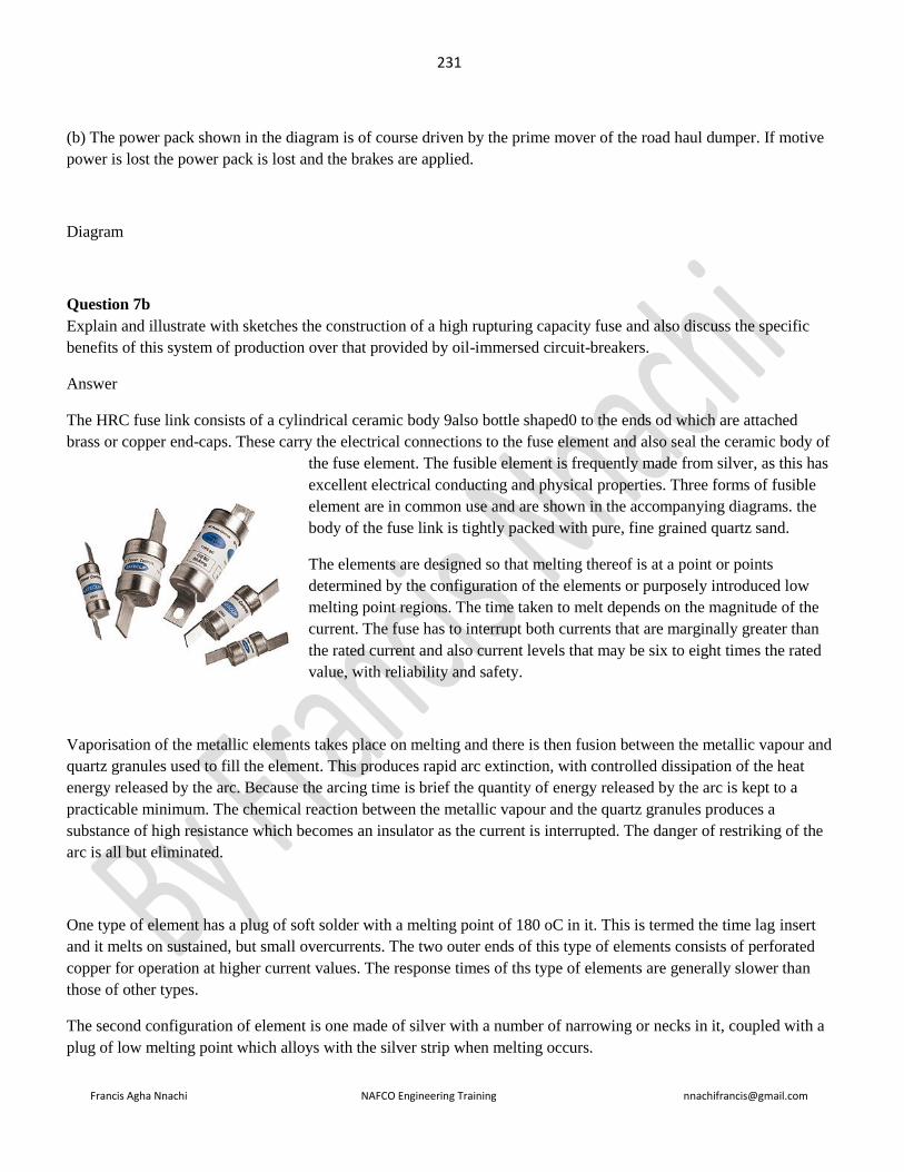
231
Francis Agha Nnachi NAFCO Engineering Training [email protected]
(b) The power pack shown in the diagram is of course driven by the prime mover of the road haul dumper. If motive
power is lost the power pack is lost and the brakes are applied.
Diagram
Question 7b
Explain and illustrate with sketches the construction of a high rupturing capacity fuse and also discuss the specific
benefits of this system of production over that provided by oil-immersed circuit-breakers.
Answer
The HRC fuse link consists of a cylindrical ceramic body 9also bottle shaped0 to the ends od which are attached
brass or copper end-caps. These carry the electrical connections to the fuse element and also seal the ceramic body of
the fuse element. The fusible element is frequently made from silver, as this has
excellent electrical conducting and physical properties. Three forms of fusible
element are in common use and are shown in the accompanying diagrams. the
body of the fuse link is tightly packed with pure, fine grained quartz sand.
The elements are designed so that melting thereof is at a point or points
determined by the configuration of the elements or purposely introduced low
melting point regions. The time taken to melt depends on the magnitude of the
current. The fuse has to interrupt both currents that are marginally greater than
the rated current and also current levels that may be six to eight times the rated
value, with reliability and safety.
Vaporisation of the metallic elements takes place on melting and there is then fusion between the metallic vapour and
quartz granules used to fill the element. This produces rapid arc extinction, with controlled dissipation of the heat
energy released by the arc. Because the arcing time is brief the quantity of energy released by the arc is kept to a
practicable minimum. The chemical reaction between the metallic vapour and the quartz granules produces a
substance of high resistance which becomes an insulator as the current is interrupted. The danger of restriking of the
arc is all but eliminated.
One type of element has a plug of soft solder with a melting point of 180 oC in it. This is termed the time lag insert
and it melts on sustained, but small overcurrents. The two outer ends of this type of elements consists of perforated
copper for operation at higher current values. The response times of ths type of elements are generally slower than
those of other types.
The second configuration of element is one made of silver with a number of narrowing or necks in it, coupled with a
plug of low melting point which alloys with the silver strip when melting occurs.
232
Francis Agha Nnachi NAFCO Engineering Training [email protected]
The third type of element is used to provide either quick-acting or slow-acting characteristics by the introduction of
an alloying substance which has fusing temepertaure less than that of silver. The characteristic time-current curves of
the type of element are continuous, as for the send type, but the slow acting curve is modified in its slope for times
greater than 1 seconds.
………………………
Question 8
Provide a concise explanation of the weaknesses and benefits, especially those peculiar to South Africa, of the use of
electricity from battery packs as a source of energy for road vehicles, in place of fossil fuels in the vehicles. (5
marks)
Answer
The leading industrial nations of the world have put a huge amount of effort and research into both electric motors
and batteries suitable application to road vehicles. As far as the design and development of motor, motor control,
regenerative braking, running gear and aerodynamic body shells are concerned positive results have been obtained.
Very acceptable road performance has been demonstrated by numerous manufacturers. With regard to passenger
vehicles compact motors of up to 30 kW output with sophisticated control equipment can propel two and four seater
machines to some 140 km/h terminal velocities and provide 0 to 100 km/h acceleration in the 10 to 11 second
bracket.
The area of research which has produced a variety of alternatives, but no practical solutions is that of the storage of
electrical energy on the vehicle and the rate at which electrical energy can be introduced to the storage facility. Early
methods, which are still in use today, are the lead acid accumulator. From boat, through car, truk and tractor to
aircraft, this remains the way of storing electricity. Numerous other types of battery exist and are in production, such
as nickel cadmium and sulphur types, but all suffer from the same difficulties. These are, among others, tha,
The density of energy is low (i.e. a large volume is taken up in which only a relatively small quantity of energy is
stored.
Battery packs are not only bulky, but are also particularly heavy
The rate at which energy can be introduced into these batteries is many orders of magnitude lower than that at which
a liquid or solid fuel can be placed into a storage facility.
Battery performance can be affected by temperature
Recharging can only take place at a very limited number of venues.
Here lies the major problem with vehicles of this type. A large proportion of both the mass and the volume of the
vehicle are taken up by its energy storage facility (six to ten times that of liquid fuel) to provide a very mediocre
range of some 120 to, at the outside, 150 km. this is a quarter to a fifth of typical present day passenger car ranges.
This short range has to be expertly managed so as to get to one of the very limited number of recharging points. Once
at the recharging point a delay of in the order of five hours occurs, as this is presently a more or less optimal rate.

233
Francis Agha Nnachi NAFCO Engineering Training [email protected]
Consider a 960 km rout, travelled at 80 km/h, with a reliable range of 120 km and an adequate number of recharging
points along the way. Seven recharging stops are required. Total time will be 12 h for driving and say 7 x 5 = 35 for
recharging which is a total of 47 h! An equivalent road performance, liquid fuel vehicle would carry a much greater
payload and some 12.5 hours.
The benefits of electric power for vehicles
- Relative silence of operation, thereby reducing noise pollution
- Emission free operation (although, where the source power is generated at a thermal or nuclear power
station there are of course quantities of pollutants generated, but as these are then more or less
centralized control of these can be more readily effected) thereby limiting environmental pollution.
- Where source power is generated from renewable sources, such as hydroelectric power stations, road
transport is achieved without depleting fossil fuel reserves (this not apply to S.A)
- With source power generated from coal and uranium, both of which S.A has large reserves of, electrical
road transport takes place without depletion of oil reserves, of which S.A does not appear to have
prodigious reserve.
================================================================================
June 1992
===========================================================================
Question 1
State four means of identifying the “stalled” condition of a fan and also explain what steps should be taken to resolve
such case. (7 marks)
Answer
234
Francis Agha Nnachi NAFCO Engineering Training [email protected]
As resistance to flow increases (i.e. the pressure rises) from the optimum delivery range a point will be reached at
which there are two or more deliveries for a single system pressure. The fan then “hunts” or stall between these
deliveries.
Indication of this “stalled” condition can include,
- Dissonance
- Drastic drop in flow rate
- Surging of the air flow (buffeting)
- Vibration
- Large, rapid fluctuation of motor amperage, etc.
- The problem exists because of either additional resistance to air flow or loss of power at the fan prime
mover, through either voltage drop, loss of a phase or motor malfunction
Thus, to correct the problem there is either immediate
- Removal of the obstruction to flow or
- Isolation of the fan motor and the impediment to flow (from say clogged filters, closed dampers, etc) or
electrical fault is remedied.
Question 2(a)
State FOUR types of motor protection other than thermal overload, and state the purpose of each one. (6 marks)
Answer
1. Phase failure relay (also phase reversal relay) to prevent the motor attempting to run with one phase dead or
two phases reversed.
2. Low voltage sensing coils connected to a contactor so as to prevent motor running at too low supply voltage
3. Overvoltage protection
4. Lighting surge protection
5. Overcurrent protection, as distinct from thermal overload protection which will isolate the supply, very
rapidly, at any preset current value.
6. Frequency monitoring, should there be any need to isolate the supply in the event of frequency deviation.
Question 3(a)
When passenger rope attachments and ancillary supporting equipment are fabricated quality control has to be
exercised. Expound the quality control measures that are to be applied. (10 marks)
Answer

235
Francis Agha Nnachi NAFCO Engineering Training [email protected]
Quality control, in this context, has to be applied to four discrete phases of the task in question, namely;
- Design of the components
- Specification, purchase and receipt of materials to use in the design
- Actual manufacture of componentry from the design and the material purchased
- Installation of componentry
Rope connections are subject to fluctuating stresses and as such can be prone to fatigue. Thus in achieving the
required integrity of design the quality control that is exercised must ensure that design stresses are kept to less than
the endurance limit of the materials, where this is applicable, sudden changes of section of components are avoided,
that there are no other stress raisers designed into components and that provision of protection against accidental
disconnection is incorporated in the design.
Specification of material to use must take metal fatigue into account, ideally materials with excellent fatigue
resistance, such as high manganese steels, should be used wherever possible. Similarly, materials with qualities to
suit the manufacturing processes involved, such as good machinability, heat treatability, etc must be specified.
Quality control has to ensure that not only are most satisfactory types of material specified, but that these are actually
purchased, received, identified, stored and issued to the intended jobs at the place where the work is performed.
Quality control then has to ensure that the correct materials are used for the correct components and that the required
methods are used during manufacture. Inspection during and after manufacture will ensure compliance with such
issues as,
- Adherence to specified dimensions
- Use of correct manufacturing techniques (mig or tig welding, if required, rolled threads, if necessary,
heat treatment, etc),
- Components free of sudden dimension changes and other stress raisers
- Presence of facilities to prevent ropes “untwisting” and accidental disconnection
During and immediately after installation quality control has to ensure, inter-alia, that
a). the correct components, as specified, are used in the correct applications,
b). rope thimble to crown bar connections incorporate correct springs, m
c). workmanship is of a satisfactory standard insofar as ropes being free of kinks, or having “untwisted”, white
metalling of rope ends in thimbles is homogenous and rope strands are correctly splayed and locked, anti-spin
measures, such as a length of wire rope secured through all thimble eyes, are installed, measures to prevent
accidental disconnection, such as lock nuts on and split pins through rope thimble studs are fitted.
Question 6(a)
Explain why too much water in a mixture of concrete weakens the final product (4 marks)

236
Francis Agha Nnachi NAFCO Engineering Training [email protected]
Answer
The cement used in concrete has, through the method of production, undergone a chemical change in which the water
of crystalisation has been driven off. When the cement is hydrated, i.e. water is added, a chemical reaction takes
place, in which the water combines with the cement. The amount of water required for the necessary chemical
change is precise and is determined by the chemical reaction.
In normal practice more water than that which will combine with the cement is used in the preparation phase. This is
largely due to the fact that the “wetter” the mix the more easily the batch can be worked.
The water that does not chemically bond with the cement increases the volume of the paste. After curing, the
chemical bonding of the dehydrated cement and the added water, to produce a new compound, the excess water
evaporates. This results in excessive shrinkage of the concrete. In addition to this the excess water in the paste
occupies small spaces, interstices, in the paste and after curing and evaporation these interstices remain as voids
which weaken the cured concrete.
Concrete mixes which contain too much water are also prone to having the cement rich paste float to the surface of
the wet concrete. In so doing there is separation of sand, aggregate and cement and frequently the cement slurry runs
off the mix. Obviously such concrete is neither satisfactorily homogenous nor does it have the design strength of the
original mix.
In summary, too much water in the mix weakens the end product.
Question 7(a)
Sketch the complete circuit showing the motor and motor control components of main isolator, line contactor, motor
windings, marked U1-U2, V1-V2, and W1-W2, star contactor and delta contactor.
Answer
Star-delta starting
This method is used for motors which are built to run normally with a delta-connected stator winding. It will start in
star and then it will be switched over to run at normal speed in delta.
This method is cheap and effective, provided that the starting torque is required not to be more than 1.5 times the
full-load torque. It is normally used for pumps, machine tools, etc.
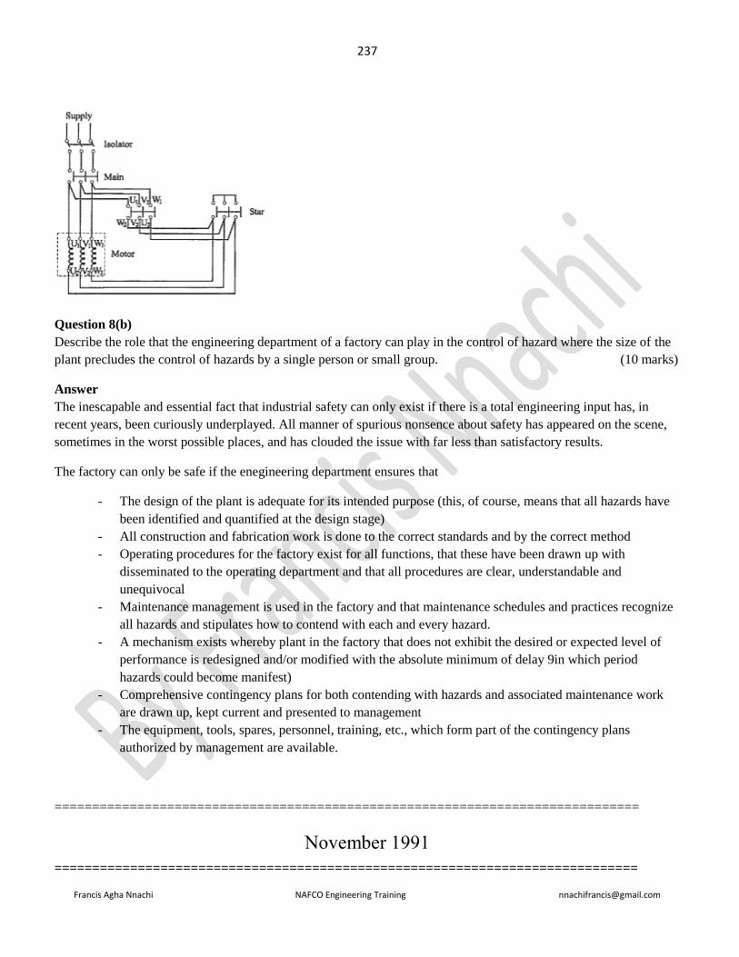
237
Francis Agha Nnachi NAFCO Engineering Training [email protected]
Question 8(b)
Describe the role that the engineering department of a factory can play in the control of hazard where the size of the
plant precludes the control of hazards by a single person or small group. (10 marks)
Answer
The inescapable and essential fact that industrial safety can only exist if there is a total engineering input has, in
recent years, been curiously underplayed. All manner of spurious nonsence about safety has appeared on the scene,
sometimes in the worst possible places, and has clouded the issue with far less than satisfactory results.
The factory can only be safe if the enegineering department ensures that
- The design of the plant is adequate for its intended purpose (this, of course, means that all hazards have
been identified and quantified at the design stage)
- All construction and fabrication work is done to the correct standards and by the correct method
- Operating procedures for the factory exist for all functions, that these have been drawn up with
disseminated to the operating department and that all procedures are clear, understandable and
unequivocal
- Maintenance management is used in the factory and that maintenance schedules and practices recognize
all hazards and stipulates how to contend with each and every hazard.
- A mechanism exists whereby plant in the factory that does not exhibit the desired or expected level of
performance is redesigned and/or modified with the absolute minimum of delay 9in which period
hazards could become manifest)
- Comprehensive contingency plans for both contending with hazards and associated maintenance work
are drawn up, kept current and presented to management
- The equipment, tools, spares, personnel, training, etc., which form part of the contingency plans
authorized by management are available.
==============================================================================
November 1991
=============================================================================

238
Francis Agha Nnachi NAFCO Engineering Training [email protected]
Question 1(a)
The gears in a slow running gearbox are observed to exhibit deep pitting on the bearing surfaces of the spur gear
teeth and a measure of plastic deformation of the teeth. Provide possible reasons for the pitting and deformation and
suggest remedial measures. (6 marks)
Answer
i). Pitting of gear teeth stems from the fact that teeth are subjected to simultaneous rolling and sliding contact. The
life of the contact surfaces are determined by the surface strength of the material from whioch the teeth are
manufactured.
When two surface roll and slide against one another with force, as is the case with meshing gears, pitting failure
occurs after a certain number of cycles of operation. The mechanism of the pitting is ascribed to
- hertz stresses,
- number of cycles,
- surface finish,
- hardness,
- degree of lubrication
- temperature
ii). Deformation is caused by stress levels which exceed the elastic limit of the material. This causes localized
portions to go into the plastic phase and undergo permanent, inelastic strain. The phenomenon of creep can be
investigated with respect to this issue.
- Obviously corrective measures for the pitting must centre around such measures as improving
lubrication,
- Improving surface finish of new gears of the same material as those which pit,
- Reducing the temperature at which the gears run
- Using material of greater surface strength and or hardness for new gears
- Reducing load on the gear
- Reducing vibration of the gear set, etc.
To counter deformation steps such as reduction of load on the gears and thereby reduction of applied direct stress and
Use of gear material of increased limit of elasticity strength (and yield stress) can be considered.
Question 2
Explain the generation of transients on transmission lines when faults are cleared by means of circuit breakers.
(6 marks)
Answer
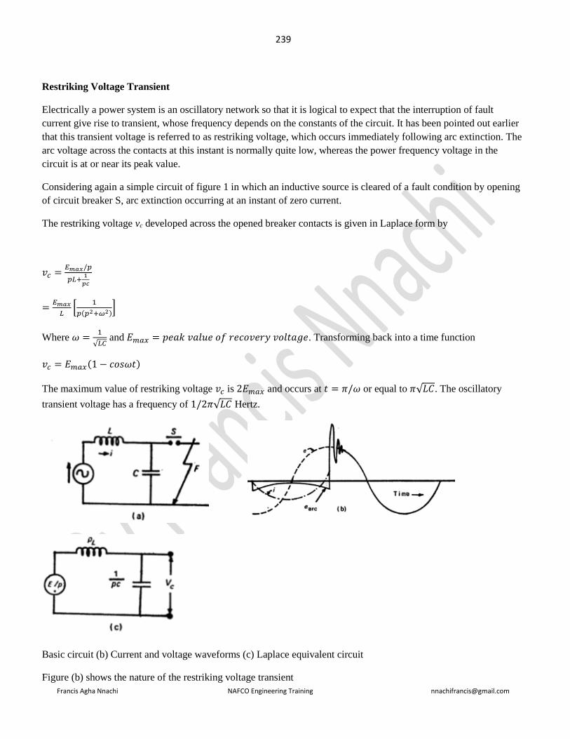
239
Francis Agha Nnachi NAFCO Engineering Training [email protected]
Restriking Voltage Transient
Electrically a power system is an oscillatory network so that it is logical to expect that the interruption of fault
current give rise to transient, whose frequency depends on the constants of the circuit. It has been pointed out earlier
that this transient voltage is referred to as restriking voltage, which occurs immediately following arc extinction. The
arc voltage across the contacts at this instant is normally quite low, whereas the power frequency voltage in the
circuit is at or near its peak value.
Considering again a simple circuit of figure 1 in which an inductive source is cleared of a fault condition by opening
of circuit breaker S, arc extinction occurring at an instant of zero current.
The restriking voltage vc developed across the opened breaker contacts is given in Laplace form by
𝑣𝑐 =𝐸𝑚𝑎𝑥/𝑝
𝑝𝐿+1
𝑝𝑐
=𝐸𝑚𝑎𝑥
𝐿[
1
𝑝(𝑝2+𝜔2)]
Where 𝜔 =1
√𝐿𝐶 and 𝐸𝑚𝑎𝑥 = 𝑝𝑒𝑎𝑘 𝑣𝑎𝑙𝑢𝑒 𝑜𝑓 𝑟𝑒𝑐𝑜𝑣𝑒𝑟𝑦 𝑣𝑜𝑙𝑡𝑎𝑔𝑒. Transforming back into a time function
𝑣𝑐 = 𝐸𝑚𝑎𝑥(1 − 𝑐𝑜𝑠𝜔𝑡)
The maximum value of restriking voltage 𝑣𝑐 is 2𝐸𝑚𝑎𝑥 and occurs at 𝑡 = 𝜋/𝜔 or equal to 𝜋√𝐿𝐶. The oscillatory
transient voltage has a frequency of 1/2𝜋√𝐿𝐶 Hertz.
Basic circuit (b) Current and voltage waveforms (c) Laplace equivalent circuit
Figure (b) shows the nature of the restriking voltage transient

240
Francis Agha Nnachi NAFCO Engineering Training [email protected]
Question 3(a)
Describe the method of joining a conveyor belt with particular reference to mating and aligning the ends, curing the
joint, maintaining uniform thickness and the inspections and tests to be performed after completion of vulcanization.
(10 marks)
Answer
The portion to be mated has to be scrupulously clean. Acetone is the usual cleaning fluid. The ends are then cut at the
required bevel angle and buffed to create the correct surface texture. Ends can be aligned mechanically to be precise.
The joints is then clamped and maintained at the correct temperature for the specified length of time. The clamping
aids the establishment of uniform thickness. The strength of the joints is prejudiced by delamination. Consequently it
has to be thoroughly examined once cured to detect any evidence of such potential failure.
Question 5(a)
State the factors which have an effect on the service life of tyres used on off-road type dump trucks. (5 marks)
Answer
Factors influencing the life of a dump truck tyre include, inter alia,
- Surface on which it operates
- Temperature at which it operates
- Sustained speed at which it operates
- The actual operating regime with regard to acceleration, braking, load carried.
- Method of loading and unloading the dump truck
- Operator abuse, such as driving over boulders and other obstructions on the roadway, vicious braking,
acceleration and turning, etc.
- Inattention to routine tyre maintenance, etc.
Question 5(b)
Explain how the capital cost of a spares store of an operator of a large fleet of dump trucks can be reduced (5 marks)
Answer
The expense associated with any store is that money is spent on goods (spares) for the benefit of having these on the
premises. The money so spent is not only removed from the operating funds of the company, but also generates no
income, (directly, at any rate), for the company. It is so called dead money. To save money the spares on hand must

241
Francis Agha Nnachi NAFCO Engineering Training [email protected]
be minimised and only those that are genuinely essential must be bought. The critique of what makes a spare
essential must be very carefully set and applied and continually updated and modified.
Utilization of spares has to be carefully studied and a history of requirements established. Not only the types of
spares, but also the reason that were needed must be determined.
The local availability of both spares and repair services must be accurately established. There is no economic point in
carrying exotic spares in the store, for a period of many months or even years, to use in say a transmission repair
when it is known that these units seldom, if ever require overhaul of the transmission. Equally, why carry spares for
the hydraulic pump when the agent, who is nearby carries reconditioned exchange units?
In the same way, there is no point in carrying a large stock of the routine items such as oil, air and fuel filters, fan
belts, oil and hydraulic fluid, etc when these are available on call, from the local suppliers.
A sound programme of preventive and routine maintenance can also be considered. In this way the unit to be
overhauled can be taken out of service, at the planned, predetermined time, with minimum disruption to the fleet.
Such spares as are expected to be necessary for overhaul can be ordered shortly before the work is due to commence.
In this way the spares holding is minimised, costs are reasonably accurately budgeted for (and are allocated to
specific machine) and outlay is evenly spread over the operating (budget) year.
Question 7(a)
State the advantages of individually screened flexible cables comprising a polyphase system in hazardous location.
(5 marks)
Answer
In answering this question, direction is obtained from the keys of hazardous area and “polypase”. Ignition of the gas,
vapour or dust which causes the hazardous area must be avoided at all costs. Ignition could be caused by arcing
between (i) conductors (ii) conductors and neutral (ii) conductors and earth
By individually screening each conductor,
The dangers of flash over between phases and a phase and neutral are eliminated.
Earth leakage sensing can be provided for each phase.
Isolation of faults can be made specific
Question 7(b)
Sketch a high resistance earthing system of a polyphase reticulation system. (5 marks)
Answer

242
Francis Agha Nnachi NAFCO Engineering Training [email protected]
The purpose of a high impedance earthing circuit is to limit current through protection equipment. It must be
remembered that resistance in the earth circuit raises the voltage across the circuit.
Question 7(c)
Describe the following items
Load prediction
Reasons for harmonics in reticulation systems
High-voltage circuit breaker testing
Application of microprocessor to reticulation systems
Answer
Load prediction
Load prediction, with regard to electrical distribution systems, is the process whereby a prognosis of the electrical
demand any future, given time, on any specific day, is made. The ability is largely based on historical data, recorded
hour by hour, day by day as the system operates.
Naturally, if a new section is added to the system a reasoned determination of the demand of this extension at any
instant is added onto the existing data (or base load). The actual kVA (or MVA) demand will then be arrived at, with
accuracy, by precision monitoring with the efflux of time.
The purpose of load prediction is to lay the foundation for the operating the system economically. Both capital and
operating outlays are tailored to the requirements defined by load prediction. The maximum capacity of the system,
which represents its capital cost, is such that it exceeds the maximum demand by the smallest, practicable margin.
During day to day operation units are brought into and taken out of operation according to the fluctuations forecast
by the load prediction. In this way losses associated with having unnecessary plant on line are minimised. Equally, as
it is needed extra plant is brought into play and user satisfaction is maintained at minimal cost.
Reasons for harmonics in reticulation systems
Harmonics are produced in the output waveform of a.c generators as a result of non-sinusoidal air-pag flux
distribution and tooth ripple stemming from the slots in which the windings are located. Any non-linearity in the
circuit results in harmonics in the current waveform.
In three-phase system harmonics are produced for the same reasons as in single-phase. However, particular attention
must be paid to the third harmonic amd all mutiples of third harmonic, the triple-n harmonics. Even harmonics are
very seldom present.
243
Francis Agha Nnachi NAFCO Engineering Training [email protected]
All triple-n harmonics are in time phase ans can cause a surrent to flow in the neutral wire of a star connected four
wire system. The following can be shown mathematically for 3-phase system
These triple-n harmonic also have an effect in delta connected windings. There will be third harmonic e.m.f equal to
three times the phase value acting around the mesh. The magnitude of the circulating current is determined by the
impedance of the windings at the third frequency. Obviously this results in losses and associated heat generation.
High voltage circuit breaker testing.
Protection systems of circuits, which are based on circuit braekers., can be interconnected to other parallel circuits to
provide the necessary overlap for effective protection. Testing, per se, can be divided into the following categories:
After installation:
Objectives are to establish
- All components are in serviceable condition
- All connections are correctly made and
- Application of relay settings
Maintenance:
- Functional testing on selected equipement at predetermined intervals
- Circuit trip testing out at preset intervals and
- Major maintenance done at preset, longer intervals
When determining appropriate tests and frequency thereof the following questions provide the guidelines for action;
- What are the failure modes?
- What is the probability of failure?
- What is the users’ experience with these devices?
- What is the risk in doing a simple overall check versus a detailed muti-test?
- If that component failed what is the effect on the security of the system?
- How difficult or costly is it to carry out that test?
- Are there alternative methods whereby the integrity of the devices can be determined?
- How much self test and/or monitoring dose the device have?
- What is the risk to the system in performing the test?
- What is the risk of leaving the protection in an unserviceable condition at the conclusion of the test
Application of microprocessor to reticulation systems
There are numerous uses of microporocessors in power systems. One of particular interest is the location of faults on
transmission lines.

244
Francis Agha Nnachi NAFCO Engineering Training [email protected]
Question 8 (a)
Indicate methods whereby employees can be motivated to exhibit safe working practices so as to avoid unsafe acts
which can result in accident (5 marks)
Answer
No safe working environment can be created without the participation of senior, middle and line management. The
impetus to drive the system is imparted by the management “machine”.
Before any employee can adopt or exhibit patterns of safe working behavior he must be trained (if education, per se
is beyond him or her) in what safe and what is unsafe. Persons that do not have the skills, dexterity, insight,
comprehension, attention, concentration, etc to perform the envisaged task that were not removed during selection
must be re-assigned when the shortfalls are found in the training phase.
Hereafter, efficient supervision must be applied. While such supervision must not be stifling it must eradicate
malpractices and provide feedback to a data bank of information used in training and operating procedures.
Management and supervisory staff must lead from the front and exhibit an example of safe working practices and
procedures that is above reproach.
Recognition of satisfactory and particularly, exemplary safe working practices must be provided by
management, for all employees to see.
Within the inalienable rights of management to control its business as its investment, enterprise and entrepreneurship
entitle it to do, an open door policy in which meaningful suggestions from employees at all level is both
encouraged and rewarded, should be instituted.
Question 8 (b)
The individual facets of an accident investigation have to be identified and explained with regard to the objectives of
these items. (5 marks)
Answer
A full accident investigation must be based on an in depth overview of all the data pertaining to the accident.
The information which is obtained must be on as broad a base as possible, involving, when this can be done, the
injured party, eye witness, supervisory staff of the injured party and, if there is any suggestion of management
policy being involved, comment from senior management.
The causative agency, be it machine, structure, hand tools, vehicle, etc, must be identified. In other words, what
ever injured the employee or third party must be established.
The human agency which contributed to the cause of the accident, be this an unsafe act on the part of the injured
party, fault of another person, fault of management, unforeseen event, etc, must be determined.
Contravention of any provision of which Act is relevant to the undertaking, must be identified.
Preventive measures, which will minimize the possibility of recurrence of a similar accident, are to be identified, if
such steps exist. When applicable, such measures are to be clearly laid out and presented to management.

245
Francis Agha Nnachi NAFCO Engineering Training [email protected]
Question 8(c)
The products of combustion produced by engines which use petrol as a fuel which are harmful have to be identified
by the candidate and the cause of the harm explained. (5 marks)
Answer
The petrol that is burnt is a hydrocarbon, with numerous additives. The air used in the combustion process is, of
course, consists largely of oxygen and nitrogen.
The carbon component of the fuel combines with oxygen in the air to produce carbon monoxide, CO, and
cabondioxide, CO2. Carbon monoxide is deadly for air breathers. It is an accumulative poison, exposure to low
concentrations for protracted periods can prove fatal.
Carbon dioxide is an inert gas which, in low concentrations, holds no immediate danger for persons. In fact, it is
essential for plant life. However, current thinking suggests that the enormous release of CO2 taking place daily is
causing a collection of CO2 in the atmosphere. This in turn, has precipitated a greenhouse effect that is raising global
temperature, with potentially disastrous consequences.
High temperatures and presuures in modern petrol engines gives rise to a combination of oxygen and nitrogen to
produce various nitrous oxides, commonly identified by the generic symbology as NOx. These oxides, in turn, can
combine with atmospheric water to form acidic products. This is part of the much maligned acid rain.
Sulphur in the fuel, (not really a problem with petrol) follows the same route as nitrogen in combining with oxygen.
This, however takes place at lower temperatures and pressure than nitrogen. Here, again, the sulphurous oxides
combine with water in the atmosphere to form acidic products.
South Africa uses tetra-ethyl lead to improve the octane rating of petrol. After combustion the lead is released to the
atmosphere. A polemic of monumental proportions currently surrounds this use. Curiously, the published research on
the effects of this lead on persons in South Africa is anything but conclusive or damning. The danger associated with
lead is that it os a heavy metal accumulative poison.

246
Francis Agha Nnachi NAFCO Engineering Training [email protected]
===========================================================================
June 1991
=================================================================================
Question 2(a)i
State the main factors which influence an electrical motor’s rating
Answer
The rating of an electric motor is determined by the heat generated during operation and the ability to dissipate
that heat, i.e. keep the temperature of the motor at a level which is safe for the windings (and in limited cases
bearings and bearing lubricants).
The heat in the windings is generated by the I2R losses, where I is the current flow through the winding and R is the
winding resistance. The greater the power produced the greater the current flow and hence the much (I2) greater the
heat generated.
The limiting condition is thus the maximum temperature that the insulation of the windings can tolerate. Heat
is generally removed by airflow over the windings. Larger motors may have assisted cooling, over and above airflow
induced along the motor shaft, by means of separately powered blowers which feed a copious air stream through the
motor casing.
In consequence, rating is determined by the full load temperature rise read against the temperature tolerance
of the class of insulation used in the motor.
Question 3(a)
Provide a short explanation of the consequences of both flue gas temperature and excess combustion air on the
efficiency of a boiler. (3 marks)
Answer
Excess flue gas temperature as well as excess combustion air reduces boiler efficiency. This is as a result of the heat
energy in the fuel being carried in the flue instead of being transferred to the heating medium in the boiler, (this, of
course, is usually water). Excess temperature may indicate fouled tubes, (particularly on the water side, but also to
some extent, on the fire side. Excess combustion air introduces a mass of air to which some of the heat of
combustion is transferred only to exit via the flue without adding anything to the process and thereby robbing the
boiler of the heat it contains.
Question 3(b)
Present a line drawing of boiler plant consisting of an economiser, evaporator, super heater and air heater
Answer
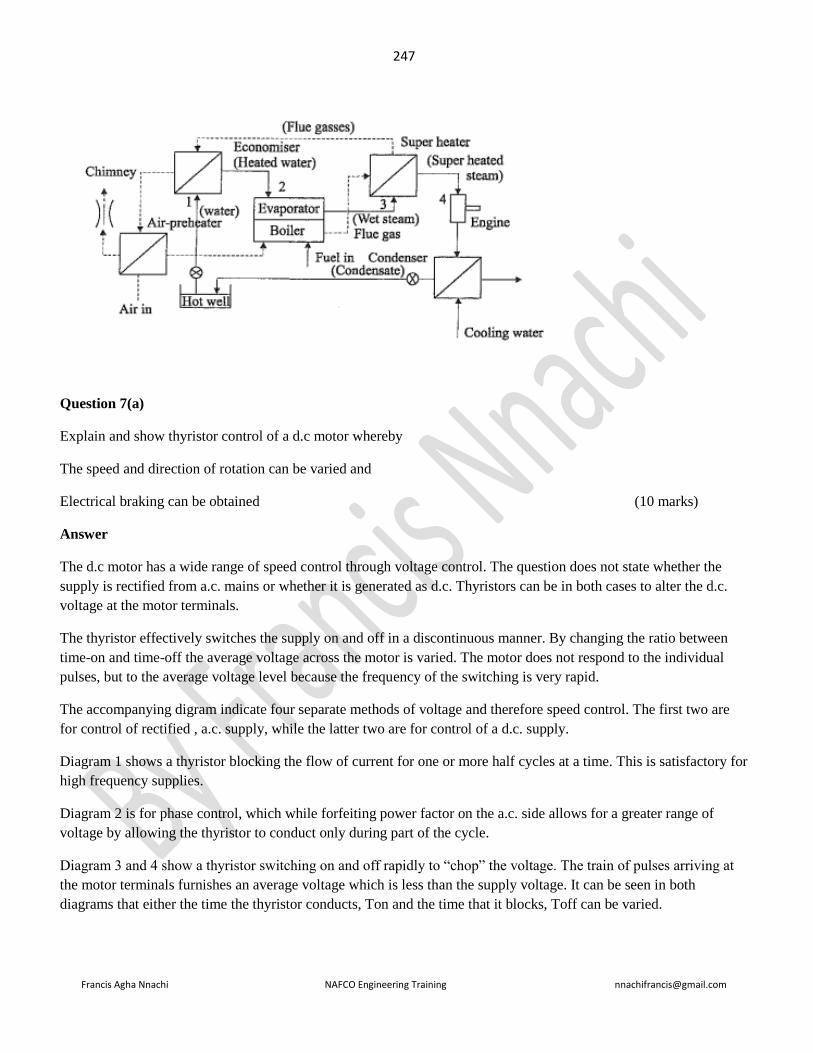
247
Francis Agha Nnachi NAFCO Engineering Training [email protected]
Question 7(a)
Explain and show thyristor control of a d.c motor whereby
The speed and direction of rotation can be varied and
Electrical braking can be obtained (10 marks)
Answer
The d.c motor has a wide range of speed control through voltage control. The question does not state whether the
supply is rectified from a.c. mains or whether it is generated as d.c. Thyristors can be in both cases to alter the d.c.
voltage at the motor terminals.
The thyristor effectively switches the supply on and off in a discontinuous manner. By changing the ratio between
time-on and time-off the average voltage across the motor is varied. The motor does not respond to the individual
pulses, but to the average voltage level because the frequency of the switching is very rapid.
The accompanying digram indicate four separate methods of voltage and therefore speed control. The first two are
for control of rectified , a.c. supply, while the latter two are for control of a d.c. supply.
Diagram 1 shows a thyristor blocking the flow of current for one or more half cycles at a time. This is satisfactory for
high frequency supplies.
Diagram 2 is for phase control, which while forfeiting power factor on the a.c. side allows for a greater range of
voltage by allowing the thyristor to conduct only during part of the cycle.
Diagram 3 and 4 show a thyristor switching on and off rapidly to “chop” the voltage. The train of pulses arriving at
the motor terminals furnishes an average voltage which is less than the supply voltage. It can be seen in both
diagrams that either the time the thyristor conducts, Ton and the time that it blocks, Toff can be varied.

248
Francis Agha Nnachi NAFCO Engineering Training [email protected]
The question does not specify what type of d.c. motor is to be reversed, i.e. shunt, compound, series or split field.
Blatantly obviously this fact influences the method in which the thyristors are used. The two accompanying diagrams
are thus of necessity general and show the arrangements for, in the first case, reversal by armature control or in the
second case, reversal through field reversal.
ii). Electrical braking can be achieved in three ways, regenerative, dynamic and counter current. In each case
thyristors are used to perform the necessary connections.
For regenerative braking, usually where the armature is driven and an overspeed condition exists, either the armature
or field connections are reversed (via thyristors, for the purpose of this question).
In dynamic braking of a shunt machine the armature circuit is disconnected and connected onto a resistance with the
field circuit remaining connected to the supply, while for a series motor either the field or armature connections have
to be reversed (via thyristors, for the purposes of this question).
While counter current braking (also termed lugging) the armature circuit is switched so that Er aids Va to produce a
large current and braking torque. (Naturally the switching is by thyristor, in this question)
Diagram ………………………….

249
Francis Agha Nnachi NAFCO Engineering Training [email protected]
==============================================================================
November 1990
==============================================================================
Question 1
With respect to plain bearing, briefly
a). explain the origin of heat generation (3 marks)
b). present three methods that reduce the generation of heat (3 marks)
c). i) describe how running hot leads to seizure and
ii) explain what seizure of metal-to-metal plain bearing is (5 marks)
Answer
The question concerns the most elementary of all bearings, the plain bearing, not a ball, or roller, or neddle roller or
nay other kind of bearing. Also, the question does not specify any form or type of lubricant whatsoever, thus liquid
lubricants such as oils, or dry lubricants such as graphite must be ignored. As far as this discussion is concerned the
plain bearing is free of any external lubricant and may perhaps use an organic liner material such as lignum-vitae, or
a synthetic material such as Vesconite.
Simple logic provides the key to answering the question. What is the purpose of a bearing? It is provided to
support an element which moves in relation to the frame.
Unfortunately a bearing unavoidably introduces the effect of friction between the moving element and the support.
(Any statement that a lubricant overcomes friction is unadulterated rubbish. Mankind, at this juncture, no more has
means of eliminating friction than of producing super conductors which function at ambient temperatures. If such
means were available the age of perpetual motion, et al, would have dawned. What a lubricant does is reduce the
coefficient of friction between moving components).
(a)
Now, the coefficient of friction is a pure number, determined by the characteristics of the materials, the support is
provided to carry a load measured in newtons and the motion is measured in terms of revolutions per minute or
seconds, or radians per seconds, or metres per second, or km/h, e.t.c.
Thus the heat generated in a bearing must be a function of
- Relative motion, say ω rad/s,
- Load supported, say W netwons and
- Coefficient of friction acting between journal and liner, say μ.

250
Francis Agha Nnachi NAFCO Engineering Training [email protected]
Stated in mathematical terms, heat generated per unit time, 𝑄 = 𝑓[𝜔; 𝑊; 𝜇]
Very basic dimensional analysis now permits the development of a quantified relationship between the factors
identified above.
Logically, Q is in joules per second, which of course, is watts
The angular velocity of the journal in rad/s multiplied by its radius, r, ωr is the linear velovity of the journal relative
to the liner, in m/s.
The radial force between journal and liner, i.e. the load the bearing supports multiplied by the coefficient of friction
is the friction force resisting motion i.e Wµ = newtons times a pur number.
Now, if linear velocity in m/s is multiplied by friction force in newtons the resultant units are watts.
So, Q = ωrWµ in, of course, watts.
There are numerous permutations of this relationship. The load carried by the baring and the projected area of the
bearing are used to determine the average pressure, in Pascals, acting on the bearing. Consequenctly an alternative
presentation is 𝑄 = 𝑓[µ; 𝑝; 𝑑; 𝑙; 𝑣]
Where p = pressure in Pa; d = bearing diameter, m; l = bearing length, m ; v = relative velocity, m/s
Therefore 𝑄 = 𝑓[𝑝; 𝑑; 𝑙; 𝜔; 𝑟; µ] etc.
(b)
Blatantly obviously heat generation is reduced by
- Reduction of interface friction, e.g. a change of liner material, provision of lubricant, better
lubricant, etc.
- Reduction of interface pressure, e.g. decrease in the load carried by the bearing, correct alignment,
provision of adequate clearances, reduction of side thrust, increase in projected area of bearing,
etc.
- Reduction of rubbing velocity, e.g. reduce speed rotation.
(c)
(i) An increase in temperature causes expansion of the journal and liner. Should the expansion be differential in that
the journal expands more than the liner and housing there is an increase in interface presuure.
From 𝑄 = µ. 𝑝. 𝑑. 𝑙. 𝑣 it is seen that the graeter p the greater q becomes. The graeter Q becomes the higher the
temperature becomes ans hence the greater p becomes, thus the process is self-perpetuating.

251
Francis Agha Nnachi NAFCO Engineering Training [email protected]
ii). The high spots of journal and liner increase in temperature to a point at which, coupled with pressure, welding of
these high spots, or asperities, one to the other, occurs.
This is complete seizure.
Question 4 (a)
All design assignments connected with factory installations, from initiation to effective conclusion, have to be
partitioned into four procedures, or time stages.
Identify each of these procedures or stages and give a concise explanation of the reason for each of these proceudres
or stages.
Answer
Feasibility study – to validate need and produce sets of possible solutions
Preliminary design – to qualify parameters so as to yield optimum solution(s)
Detail design – to reduce to the best solution a specification for manufacture or construction
Revision of detail design – to produce improved or acceptable design based on experience with a manufactured or
tested system.

252
Francis Agha Nnachi NAFCO Engineering Training [email protected]
===============================================================================
JUNE 1990
=================================================================================
Question 4 (a) (repeated June 2008 Q6.1; Nov. 2005 Q6.2; Nov 2011 Q5.3)
Give a brief description of the advantages and disadvantages of a high-impedance earthed protection system.
Answer:
Advantages of high impedance earth protection
1. Protection is very sensitive & with small fault current
2. Very little damage at the location of fault
3. Protection not wholly dependent on low impedance earth return path
4. Slight voltage rise in the faulty equipment
5. minimized danger of arcing
6. Sensitive enough to protect a person
Disadvantages of high impedance earth protection
1. Protection not selective
2. Overcurrent protection will not operate consequently not back up to earth leakage protection
3. Tripping may then be caused by harmonics, capacity imbalance or induced currents
4. difficult to locate fault
5. as the system neutral is not held at earth potential, conditions may cause the phase-to-neutral insulation of
the equipment to be subjected to line voltage
Question 8(a)
Provide a brief definition of reliability engineering in the context of machines , components and plant.
Answer
Reliability engineering deals in a scientific manner with the
- Investigation

253
Francis Agha Nnachi NAFCO Engineering Training [email protected]
- Quantification
- Specification and
- Validation
Of
- Reliability
- Availability and
- maintainability
of
- machines, components and plants.
Question 8(b)
Illustrate the similarities between the parameters of reliability engineering and the conventional engineering
parameters such as efficiency, velocity and power.
Answer
The similarities of the parameters are that all are
- Specific
- Measurable (i.e quantifiable) and
- Attainable
Question 8(c)
Define planned maintenance
Answer
Planned maintenance is managing maintenance so that optimum plant availability can be achived at minimum cost
with the best use of available resources.
Question 8(d)
State briefly the objectives of planned maintenance
Answer
Objectives of planned maintenance are

254
Francis Agha Nnachi NAFCO Engineering Training [email protected]
- Improving pant availability, efficiency and safety
- Reducing maintenance coat per unit of production
- Ensuring optimum utilization of staff
- Increasing effective life of capital equipment and
- Ensuring replacement is done at the most economic time with the most effective equipment

255
Francis Agha Nnachi NAFCO Engineering Training [email protected]
===================================================================================
NOVEMBER 1989
==================================================================================
Question 4 .
This questions deals with the system which make up effective and efficient maintenance control in a factory
environment.
- State the different conditions that have to be kept in balance by the maintenance function
- State three general time bases around which maintenance system are planned
- State the key features of the priority system which must be used
Answers
In organizing, running and managing the maintenance department of a factory or similar undertaking items such as
the following have to be kept in efficient and cost effective balance:
1. Preventive and corrective (i.e breakdown or crises) maintenance routine repair work
2. Spares carried in the company stores and those locally available
3. work on downtime and work on breakdowns
4. maintenance work and its effects on production runs
5. alterations and modifications to plant and minor construction work
6. plant and personnel safety and protection of the environment
7. sundry and incidental work
Maintenance work can be planned and organized on three broad time bases, namely
1. A short range basis dictated by the job and day, such as adjustments of equipment to correct production run
quality deviations, emergency repairs, etc.
2. A medium term basis (such as annual) so as to balance major project work, schedule planned maintenance,
perform statutory inspections, provide for orderly vacations of maintenance staff, set up maintenance
budgets, etc.
3. A long term basis (say from more than one year to ten years) to arrange, organize and ensure the availability
of proper skills, space, equipment, capital, replacement plant etc.
To be effective and functional a priority system of a maintenance control function must
1. Be assigned by both production and maintenance departments in the factory
2. Give proper recognition to every piece of equipment in the factory
3. Consider plant utilities (i.e. services such as water, electricity, roads, compreesed air, steam, etc) and their
transmission lines,
4. Consider all the various aspects of safety and environmental issues
5. Be simple enough for all involved parties to understand
6. Be rigid enough not to be abused
7. Be sufficiently flexible to cover changing circumstances

256
Francis Agha Nnachi NAFCO Engineering Training [email protected]
Question 8(c)
Explain how to find a fault in a buried 3 core pvc sheathed pilcswa cable.
Answer
Measure resistance of faulty core to shorted armouring/earth conductor/second core with a low range resistance
meter. Repeat procedure with sound core, bridged to the same element at a known distance. Calculate the fault point
by using the two different resistances and the known distance.
OR
Apply a high voltage impulse generator to the end of the cable and listen for the associated “thumping” noise along
the route of the cable by means of directional earphones. The “thumping” sound is loudest at the fault
OR
Connect an echo impulse generator to one of the cable. Enter the correct impedance characteristic. Ensure that an
identified landmark of known distance from the impulse generator is located on the screen. The fault distance is
calculated between the impulse generator and the known landmark
OR
Murray Loop Test, etc

257
Francis Agha Nnachi NAFCO Engineering Training [email protected]
===========================================================================
Appendix ===========================================================================
Additional
Question
As an engineer, part of your responsibility is a large mechanical workshop. List TEN general points which are
important with regard to safety in the workshop (5 marks)
Answer:
1) Ensure that adequate lighting is provided
2) Paint machines in accordance to SABS recommendations. Main body of machine in pastel shades and danger
points orange.
3) Mobile units to be painted in black and yellow zebra patterns.
4) Material not to be placed on the floor that there is danger of tripping.
5) Slippery floors, due to oil or grease to be avoided.
6) No loose clothing to be worn.
7) Eye protection to be provided if there is danger from flying chips.
8) Bench vices to be so arranged that when a chisel is used, other persons are protected from flying chips.
9) Shaping machines to be placed in such a manner that in the event of a tool breaking, there is no danger to
personnel.
10) Shafts, drives, grinding wheels, etc, to be guarded as effectively as practicable.
11) All files to be provided with handles.
12) The heads of chisels, drifts, punches, etc, should be such a hardness that there is no danger of cracking or
chipping and the use of such tools with “mushroomed” heads must be avoided.
13) If cranes are used, ensure that ropes, hooks, shackles and slings are kept in good condition.
----------------------------------------------------------------------------------------------------------------
Occupational Health and safety assessment series (OHSAS) 18001:2007
Occupational health and safety management systems – Requirements
NOTE This OHSAS Standard is based on the methodology known as
Plan-Do-Check-Act (PDCA). PDCA can be briefly described as follows.
• Plan: establish the objectives and processes necessary to deliver
results in accordance with the organization’s OH&S policy.
• Do: implement the processes.
• Check: monitor and measure processes against OH&S policy,

258
Francis Agha Nnachi NAFCO Engineering Training [email protected]
objectives, legal and other requirements, and report the results.
• Act: take actions to continually improve OH&S performance.
OH&S Policy requirement
Ensure that the policy
a) is appropriate to the nature and scale of the organization’s OH&S risks;
b) includes a commitment to prevention of injury and ill health and continual improvement in OH&S management
and OH&S performance;
c) includes a commitment to at least comply with applicable legal requirements and with other requirements to which
the organization subscribes that relate to its OH&S hazards;
d) provides the framework for setting and reviewing OH&S objectives;
e) is documented, implemented and maintained;
f) is communicated to all persons working under the control of the organization with the intent that they are made
aware of their individual OH&S obligations;
g) is available to interested parties; and
h) is reviewed periodically to ensure that it remains relevant and appropriate to the organization.
Planning
Hazard identification, risk assessment and determining controls
The organization shall establish, implement and maintain a procedure(s) for the ongoing hazard identification, risk
assessment, and determination of necessary controls.
The procedure(s) for hazard identification and risk assessment shall take into account:
a) routine and non-routine activities;
b) activities of all persons having access to the workplace (including contractors and visitors);
c) human behaviour, capabilities and other human factors;
d) identified hazards originating outside the workplace capable of adversely affecting the health and safety of persons
under the control of the organization within the workplace;
e) hazards created in the vicinity of the workplace by work-related activities under the control of the organization;
NOTE 1 It may be more appropriate for such hazards to be assessed as an environmental aspect.

259
Francis Agha Nnachi NAFCO Engineering Training [email protected]
f) infrastructure, equipment and materials at the workplace, whether provided by the organization or others;
g) changes or proposed changes in the organization, its activities, or materials;
h) modifications to the OH&S management system, including
temporary changes, and their impacts on operations, processes, and activities;
i) any applicable legal obligations relating to risk assessment and implementation of necessary controls
j) the design of work areas, processes, installations, machinery/equipment, operating procedures and work
organization, including their adaptation to human capabilities.
Legal and other requirements
The organization shall establish, implement and maintain a procedure(s) for identifying and accessing the legal and
other OH&S requirements that are applicable to it.
The organization shall ensure that these applicable legal requirements and other requirements to which the
organization subscribes are taken into account in establishing, implementing and maintaining its OH&S management
system.
Objectives and programme(s)
The organization shall establish, implement and maintain documented OH&S objectives, at relevant functions and
levels within the organization.
The objectives shall be measurable, where practicable, and consistent with the OH&S policy, including the
commitments to the prevention of injury and ill health, to compliance with applicable legal requirements and with
other requirements to which the organization subscribes, and to continual improvement.
Implementation and operation
Resources, roles, responsibility, accountability and authority
Top management shall demonstrate its commitment by:
a) ensuring the availability of resources essential to establish, implement, maintain and improve the OH&S
management system;
NOTE 1 Resources include human resources and specialized skills, organizational infrastructure, technology and
financial resources.
b) defining roles, allocating responsibilities and accountabilities, and delegating authorities, to facilitate effective
OH&S management; roles, responsibilities, accountabilities, and authorities shall be documented and communicated.
Competence, training and awareness

260
Francis Agha Nnachi NAFCO Engineering Training [email protected]
The organization shall establish, implement and maintain a procedure(s) to make persons working under its control
aware of:
a) the OH&S consequences, actual or potential, of their work
activities, their behaviour, and the OH&S benefits of improved personal performance;
b) their roles and responsibilities and importance in achieving conformity to the OH&S policy and procedures and to
the requirements of the OH&S management system, including emergency preparedness and response requirements
c) the potential consequences of departure from specified procedures.
Training procedures shall take into account differing levels of:
a) responsibility, ability, language skills and literacy; and
b) risk.
Communication, participation and consultation
Communication
With regard to its OH&S hazards and OH&S management system, the organization shall establish, implement and
maintain a procedure(s) for:
a) internal communication among the various levels and functions of the organization;
b) communication with contractors and other visitors to the
workplace;
c) receiving, documenting and responding to relevant communications from external interested parties.
Participation and consultation
The organization shall establish, implement and maintain a procedure(s) for:
a) the participation of workers by their:
• appropriate involvement in hazard identification, risk assessments and determination of controls;
• appropriate involvement in incident investigation;
• involvement in the development and review of OH&S policies and objectives;
• consultation where there are any changes that affect their OH&S;
• representation on OH&S matters.
Workers shall be informed about their participation arrangements, including who is their representative(s) on OH&S
matters.

261
Francis Agha Nnachi NAFCO Engineering Training [email protected]
b) consultation with contractors where there are changes that affect their OH&S.
The organization shall ensure that, when appropriate, relevant external interested parties are consulted about
pertinent OH&S matters.
Documentation
The OH&S management system documentation shall include:
a) the OH&S policy and objectives;
b) description of the scope of the OH&S management system;
c) description of the main elements of the OH&S management system and their interaction, and reference to related
documents;
d) documents, including records, required by this OHSAS Standard; and
e) documents, including records, determined by the organization to be necessary to ensure the effective planning,
operation and control of processes that relate to the management of its OH&S risks.
NOTE It is important that documentation is proportional to the level of complexity, hazards and risks concerned and
is kept to the minimum required for effectiveness and efficiency.
Control of documents
The organization shall establish, implement and maintain a procedure(s) to:
a) approve documents for adequacy prior to issue;
b) review and update as necessary and re-approve documents;
c) ensure that changes and the current revision status of documents are identified;
d) ensure that relevant versions of applicable documents are available at points of use;
e) ensure that documents remain legible and readily identifiable;
f) ensure that documents of external origin determined by the organization to be necessary for the planning and
operation of the OH&S management system are identified and their distribution controlled; and
g) prevent the unintended use of obsolete documents and apply suitable identification to them if they are retained for
any purpose.
Operational control
The organization shall determine those operations and activities that are associated with the identified hazard(s)
where the implementation of controls is necessary to manage the OH&S risk(s). This shall include the management
of change (see 1 planning).

262
Francis Agha Nnachi NAFCO Engineering Training [email protected]
For those operations and activities, the organization shall implement and maintain:
a) operational controls, as applicable to the organization and its activities; the organization shall integrate those
operational controls into its overall OH&S management system;
b) controls related to purchased goods, equipment and services;
c) controls related to contractors and other visitors to the workplace;
d) documented procedures, to cover situations where their absence could lead to deviations from the OH&S policy
and the objectives;
e) stipulated operating criteria where their absence could lead to deviations from the OH&S policy and objectives.
Emergency preparedness and response
The organization shall establish, implement and maintain a
procedure(s):
a) to identify the potential for emergency situations;
b) to respond to such emergency situations.
Checking
Performance measurement and monitoring
The organization shall establish, implement and maintain a procedure(s) to monitor and measure OH&S performance
on a regular basis. This procedure(s) shall provide for:
a) both qualitative and quantitative measures, appropriate to the needs of the organization;
b) monitoring of the extent to which the organization’s OH&S objectives are met;
c) monitoring the effectiveness of controls (for health as well as for safety);
d) proactive measures of performance that monitor conformance with the OH&S programme(s), controls and
operational criteria;
e) reactive measures of performance that monitor ill health, incidents (including accidents, near-misses, etc.), and
other historical evidence of deficient OH&S performance;
f) recording of data and results of monitoring and measurement sufficient to facilitate subsequent corrective action
and preventive action analysis.

263
Francis Agha Nnachi NAFCO Engineering Training [email protected]
If equipment is required to monitor or measure performance, the organization shall establish and maintain procedures
for the calibration and maintenance of such equipment, as appropriate. Records of calibration and maintenance
activities and results shall be retained.
Evaluation of compliance
The organization shall establish, implement and maintain a procedure(s) for periodically evaluating compliance with
applicable legal requirements
The organization shall evaluate compliance with other requirements to which it subscribes.
The organization shall keep records of the results of the periodic evaluations.
Incident investigation, nonconformity, corrective action and preventive action
Incident investigation
The organization shall establish, implement and maintain a
procedure(s) to record, investigate and analyse incidents in order to:
a) determine underlying OH&S deficiencies and other factors that might be causing or contributing to the occurrence
of incidents;
b) identify the need for corrective action;
c) identify opportunities for preventive action;
d) identify opportunities for continual improvement;
e) communicate the results of such investigations.
Nonconformity, corrective action and preventive action
The organization shall establish, implement and maintain a procedure(s) for dealing with actual and potential
nonconformity(ies) and for taking corrective action and preventive action. The procedure(s) shall define
requirements for:
a) identifying and correcting nonconformity(ies) and taking action(s) to mitigate their OH&S consequences;
b) investigating nonconformity(ies), determining their cause(s) and taking actions in order to avoid their recurrence;
c) evaluating the need for action(s) to prevent nonconformity(ies) and implementing appropriate actions designed to
avoid their occurrence;
d) recording and communicating the results of corrective action(s) and preventive action(s) taken; and
e) reviewing the effectiveness of corrective action(s) and preventive action(s) taken.
Control of records

264
Francis Agha Nnachi NAFCO Engineering Training [email protected]
The organization shall establish and maintain records as necessary to demonstrate conformity to the requirements of
its OH&S management system and of this OHSAS Standard, and the results achieved.
Internal audit
The organization shall ensure that internal audits of the OH&S management system are conducted at planned
intervals to:
a) determine whether the OH&S management system:
1) conforms to planned arrangements for OH&S management, including the requirements of this OHSAS Standard;
and
2) has been properly implemented and is maintained; and
3) is effective in meeting the organization’s policy and objectives;
b) provide information on the results of audits to management.
Audit procedure(s) shall be established, implemented and maintained that address:
a) the responsibilities, competencies, and requirements for planning and conducting audits, reporting results and
retaining associated records; and
b) the determination of audit criteria, scope, frequency and methods.
Selection of auditors and conduct of audits shall ensure objectivity and the impartiality of the audit process.
Management review
Top management shall review the organization’s OH&S management system, at planned intervals, to ensure its
continuing suitability, adequacy and effectiveness. Reviews shall include assessing opportunities for improvement
and the need for changes to the OH&S management system, including the OH&S policy and OH&S objectives.
Records of the management reviews shall be retained.
Input to management reviews shall include:
a) results of internal audits and evaluations of compliance with applicable legal requirements and with other
requirements to which the organization subscribes;
b) the results of participation and consultation
c) relevant communication(s) from external interested parties,
including complaints;
d) the OH&S performance of the organization;
e) the extent to which objectives have been met;

265
Francis Agha Nnachi NAFCO Engineering Training [email protected]
f) status of incident investigations, corrective actions and preventive actions;
g) follow-up actions from previous management reviews;
h) changing circumstances, including developments in legal and other requirements related to OH&S; and
i) recommendations for improvement.
The outputs from management reviews shall be consistent with the organization’s commitment to continual
improvement and shall include any decisions and actions related to possible changes to:
a) OH&S performance;
b) OH&S policy and objectives;
c) resources; and
d) other elements of the OH&S management system.
Relevant outputs from management review shall be made available for communication and consultation.
NOTE This OHSAS Standard is based on the methodology known as Plan-Do-Check-Act (PDCA). PDCA can be
briefly described as follows.
—— Plan: establish the objectives and processes necessary to deliver results in accordance with the organization’s
OH&S policy.

266
Francis Agha Nnachi NAFCO Engineering Training [email protected]
—— Do: implement the processes.
—— Check: monitor and measure processes against OH&S policy, objectives, legal and other requirements, and
report the results.
—— Act: take actions to continually improve OH&S performance.
Past questions
Nov. 2006 Question3
State Six general requirements that an occupational health and safety policy should include
State six items or documents to be considered for the planning stage of an OHSMS
Discuss the implementation and operation elements of the OHSMS
Nov. 2008 Question 3
3.1 An organization has established an occupational health and safety management system that is maintained. The
employer authorized an OHS policy that clearly states overall health and safety objectives and a commitment to
improving health and safety performance.
List SEVEN requirements that should be contained in the employers OHS policy.
3.2 Compile a safety procedure in a 22 kV substation before switching operations may take place
3.2 What is the main purpose of a risk-based inspection programme?
Answer
The purposes of RBI include:
1. To move away from time based inspection often governed by minimum compliance with rules, regulations
and standards for inspection.
2. To apply a strategy of doing what is needed for safeguarding integrity and improving reliability and
availability of the asset by planning and executing those inspections that are needed.
3. To provide economic benefits such as fewer inspections, fewer or shorter shutdowns and longer run length.
4. To safeguard integrity.
5. To reduce the risk of failure.

267
Francis Agha Nnachi NAFCO Engineering Training [email protected]
June 2009 Q 3.2
3.2. The employer must establish an occupational health an occupational health and safety management system
(OHSMS).
3.2.1 State Six items or documents to be considered for the planning stage of an OHSMS.
3.2.2 Discuss the implementation and operation elements of the OHSMS
Nov 2009 Q 3.3
An employer should identify key performance parameters for its occupational health and safety performance across
the whole organization in the checking and corrective action of OHSMS
Name SIX parameters that should be included –
Nov 2010 Q3
3.1 Health and safety Management system (HSMS) prescribed by chief inspector in Government notice R. 859 of 2
september 2005 requires that you must establish an occupational health and safety policy for your factory. The policy
shall clearly state the overall health and safety performance. State Six requirements of the policy.
Answer
OH&S Policy requirement
Ensure that the policy
a) is appropriate to the nature and scale of the organization’s OH&S risks;
b) includes a commitment to prevention of injury and ill health and continual improvement in OH&S management
and OH&S performance;
c) includes a commitment to at least comply with applicable legal requirements and with other requirements to which
the organization subscribes that relate to its OH&S hazards;
d) provides the framework for setting and reviewing OH&S objectives;
e) is documented, implemented and maintained;
f) is communicated to all persons working under the control of the organization with the intent that they are made
aware of their individual OH&S obligations;
g) is available to interested parties;
h) is reviewed periodically to ensure that it remains relevant and appropriate to the organization.
i) signed by the CEO
j) prominently displayed
268
Francis Agha Nnachi NAFCO Engineering Training [email protected]
3.2 The occupational health and safety management system (OHSMS 18002: 2000)- Guidelines for the
implementation of OHSAS 18001. Name Eight typical inputs that should be considered as part of the planning phase.
Answer
• Hazard identification, risk assessment and determining controls
• Legal and other OH&S requirements
• Competence, training and awareness
• Communication, participation and consultation
• Control of documents
• Operational control
• Emergency preparedness & response
• Performance measurement and monitoring
• Evaluation of compliance
• Incident investigation, nonconformity, corrective & preventive action
• Control of records
• Internal audit
==============================================================================
Behavioural Based Safety
=============================================================================
About Behavioral Safety
This section of the site is about Behavioral Safety's foundations. It covers Behavioral Safety implementation pitfalls,
what it is and isn't, and other useful information to either help in your considerations to use Behavioral Safety or to
help you identify improvement opportunities to fine-tune your existing process.
A Brief Overview of Behavioral Safety
Since the late 1980's - early 1990’s Behavioral Safety has fast become an established weapon in the war on
workplace accidents, as its use has helped many companies to dramatically slice through their accident plateau,
something that hitherto could only be dreamed of. A vast body of scientific research testifies to the effectiveness of
Behavioral Safety initiatives across a wide range of industries in many countries. Many companies, for example,
have experienced 40-75 percent falls in their accident rates within the first six to twelve months of using Behavioral
Safety.
Given that 96 percent of all workplace accidents are triggered by unsafe behavior, most will be aware that reducing
accidents and improving safety performance can only be achieved by systematically focusing upon those unsafe
behaviors in the workplace. For example, ducking under or climbing over assembly lines to reach the controls, not
269
Francis Agha Nnachi NAFCO Engineering Training [email protected]
re-stocking the ppe store, not reporting machinery defects, etc., are all unsafe behaviors. These are in the direct
control of the people engaging in them, and therefore can be targeted for improvement via Behavioral Safety.
Clarifying the Objectives
Most companies have one objective in mind when considering the use of Behavioral Safety: Reducing Incident
Rates. This means companies are concerned to ensure people are not being hurt and reducing the associated costs.
Other common objectives surround the involvement of the workforce in the companies safety efforts to help acheive
a 'Safety Partnership'.
Locate the problem
Behavioral Safety processes attempt to identify the small proportion of unsafe behaviors implicated in the majority
of accidents. Commonly, this is done by examining a facilities incident rates for the previous 2-3 years to identify the
'repeat' behaviors involved. Some will use 'Pareto' analysis to separate these 'repeat' behaviors into groups (e.g. Line
of Fire, Body Positioning) that occur 'significantly' more than others.
Some will then conduct a 'functional analysis' to identify the drivers for the 'identified' unsafe or 'at-risk' behaviors
and the consequences to those involved that maintain these behaviors. The purpose is to decide whether or not
'external factors' such as poor standard operating procedures or inadequate PPE, 'drives' people to behave unsafely.
Once found, attempts are made to 'correct' the negative workplace factors so that it is natural for people to behave
safely. In principle, people often behave unsafely when they do not know what, when or how to do something: i.e.
they need training or education of some sort. The other main reason is related to 'obstacles' or blockages to
performing safely (e.g. the right equipment is unavailable). If the conditions are optimal, then people often behave
safely because they want to (e.g. take a short-cut to get the job done quicker). Behavioral Safety specialists will
usually try to identify and put in place those 'drivers' and consequences that will support the desired safe behaviors.
Execute the Change Strategy
To obtain people's 'buy-in', a series of 'briefings' should be conducted that inform everybody about the
implementation of the intended process, what it means to them and what they will be asked to do.
The safe behaviors and/or the results of safe behaviors (i.e., safe conditions) identified from the incident records are
placed on workgroup or location specific checklists. Some will restrict the number to 3-20 specific behaviors, while
others use a 'generic' list of behaviors (e.g. Line of Fire, Eyes on Path, etc.) on an 'Observation Card' in an attempt to
cover every possible 'unsafe' or 'at-risk' behavior. Whichever type of observation instrument is used, those who
engage in the behaviors should agree the behaviors on them are important and within their control.
Other types of checklists should be developed for managerial behaviors (Senior, Middle and Front-line Supervision)
and support staff (e.g. finance, purchasing and supply, engineering, etc.,) that support safety in general and the
Behavioral Safety process in particular. These should be developed in conjunction with the different parties and are

270
Francis Agha Nnachi NAFCO Engineering Training [email protected]
usually restricted to 10 or so behaviors that these people can undertake each and every week. The impact can be
enormous (see Safety Leadership in Construction for an example).
Typically, trained observers make use of the Safety Behavior Observation instruments to monitor and record the
safety behavior of their colleagues on a regular basis (e.g., daily). Observers may also (and often do) provide verbal
feedback at the point of observation to facilitate corrective actions. Managers and support staff complete their
Support Checklists once per week. All the recorded observations are usually computed to provide feedback.
Assess Current progress
The recorded observations form the basis for feedback via graphical charts or written performance summaries, so
individuals or workgroups can track their progress against self-set or assigned targets. Depending on the design of
the process the feedback either goes to the people in the workgroups themselves each and every week, or to a
'Steering Committee' each and every month. Some also provide a 'monthly overview to the site management team.
Some compute a 'Percent Safe' score for each workgroup and/or highlight the best/worst scoring behaviors, while
others simply present 'Participation Rates' (i.e. the number of active observers in a facility). There are numerous
types of 'Key Performance Indicators' for Behavioral Safety, but these are not used as widely as they could be. Some
but not all types of process build in 'celebrations' for rmilestone achievements
Review and Adapt
Regular and thorough 'reviews' of the Behavioral Safety process are essential to ensure sustainability. Often these do
not occur. In my view, there should be regular independent reviews in the first 2 years of implementation (e.g. bi-
annually or quarterly) and annually thereafter. These reviews should be conducted by knowledgeable people (in-
house or outside 'expert). The results of the review are used to adapt to 'fine-tune' the process so that it continues to
achieve its objectives.
Comments
It must be stressed that a Behavioral Safety process is not a ‘cure all panacea’ that replaces other safety efforts.
Unfortunately, they are often seen in this way, even when there is still much to do to improve the working
environment and the organization’s safety systems. Consequently, an ill-defined process can create a lot of
unnecessary tension. This is because employees believe that management is only concerned with trivial issues
compared to safety improvements that require capital expenditure or considerable effort. In turn, this leads to
employees viewing Behavioral Safety as a convenient way for management to dodge their safety responsibilities and
apportion blame to the workforce.
To avoid problems, a ‘behavioral safety’ process will meet certain essential criteria (Sulzer-Azeroff& Lischeid,
1999). Although, the widespread use of behavioral safety is welcome there is a very real danger that some systems
do not incorporate these essential ingredients. The factors for success and typical outcomes are on the next two
pages.

271
Francis Agha Nnachi NAFCO Engineering Training [email protected]
Typical Outcomes
There are many positive 'value-added' outcomes that are within reach of those using an effective Behavioral Safety
process. A well designed and executed Behavioral Safety process should lead to:
1. Improved levels of quantified safety behaviors: If the workforce have ‘bought-in’ to Behavioral Safety
and are actively trying to improve their safety performance, logic again dictates that the levels of safe behavior will
increase. This improvement should also be visible at the workface. For example, people are following procedures,
and people are visibly engaging in safe behaviors.
2. Reduced numbers of accidents or incidents, near-misses and property damage: If the checklists are
targeting incident causing behaviors, logic dictates that as those unsafe behaviors are bought under control there
should be a corresponding decrease in the incidents and near-misses triggered by those unsafe behaviors.
3. Reduced incident costs: Logic again dictates that reductions in the number of incidents should also decrease
the associated costs. These can be measured, for example, by reductions in insurance claims and premiums,
reductions in penalties and sanctions imposed by the judiciary, reductions in the types and numbers of actual injuries,
and less time spent recording and investigating incidents.
4. Increased reporting of defects, near misses, accidents, etc: The increased reporting of defects or unsafe
conditions is an inevitable outcome of a good behavioral safety process, as the workplace observers will be noting
these, or they will be bought to their attention by their colleagues, during their observation tours. People are also
more likely to report accidents and near misses (hits?) as they learn to trust the process. However, if a ‘blame the
victim’ culture exists, incidents and near-misses are unlikely to be reported as it has negative connotations for those
who do.
5. Identification of related system issues: Effective Behavioral Safety processes identify and address other
health & safety challenges (e.g. unsafe conditions, management system faults and technological defects).
6. Improved Corrective Action rate: This outcome refers to the effectiveness of follow up procedures for
people’s improvement suggestions and for the completion of corrective actions. Indeed this feature is probably one
of the most important elements for people to continue engaging in the process. No follow up action will rapidly lead
to the rejection of the Behavioral Safety process by the workforce.
272
Francis Agha Nnachi NAFCO Engineering Training [email protected]
7. Improved people skills. Behavioral Safety training often includes elements on verbal and non-verbal
communication and the use of positive reinforcement. These skills translate to many areas beyond Behavioral Safety.
8. Better Safety Leadership: Behavioral Safety often leads to managers consistently demonstrating their
safety leadership, which has many positive 'spin-offs'. The leadership skills, again often translate into other
operational areas (e.g. Quality, Production, etc,).
What Defines Behavioral Safety
Many believe that if they are doing something to improve safety and it involves people's behavior then they are doing
'Behavioral Safety'. This is not always true! There are a number of defining features that distinguish Behavioral
Safety from other types of safety improvement efforts. Check it out..
Behavioral Safety involves a systematic, improvement intervention; A unique feature of Behavioral Safety is the
introduction of a planned schedule of events that combine to create an overall continuous improvement intervention:
This planned schedule often begins with briefing sessions for all those work areas and departments that will be
involved. People are asked to volunteer to either become observers or part of the project team or steering committee.
These people are trained to carry out their respective duties. The project team identifies unsafe behaviors that are
placed on checklists. The approval of those being monitored is then sought to ensure they are in agreement with the
behaviors on the checklists. Once the checklists are developed the trained observers carry out observations for a
certain period of time to establish a baseline (usually a week or so), with which subsequent performance can be
compared. Once the average baseline score has been determined, the intervention is implemented at kick-off
meetings, or goal-setting sessions whereby the workgroups set improvement targets for themselves. Subsequently,
the trained observers continue to monitor their colleague’s safety behaviors on a regular basis. The observation
scores are then analysed so that fine detailed feedback can be given to those concerned on a regular basis. The
project team also monitors the data for trends so that improvements can be highlighted and praised or corrective
actions can be taken. In this way Behavioral Safety incorporates the principles of continuous improvement.
Behavioral Safety is based on observational data collection; On the basis of ‘what gets measured gets done’,
trained observers monitor their peers safety behavior on a regular basis. Obviously the greater the number of
observations, the more reliable the data is, and the more likely it is that safety behavior will improve. This is in
accordance with Heisenberg’s Uncertainty Principle, whereby the very act of observing and measuring people’s
safety behavior alters the behavior of those being observed. Thus if someone is descending the stairs without holding
the handrail and is seen by a trained observer during an observation ‘tour’, that person will probably change their
behavior to that of holding the handrail.
Behavioral Safety involves significant workforce participation: One of the reasons Behavioral Safety is so
successful is that it fully engages the workforce in safety management, perhaps for the first time in their working
lives. Traditionally, safety management has been top-down driven, with a tendency for it to become stuck at the
front-line management level. This means that those workers most likely to engage in unsafe behavior or to be hurt
have traditionally been divorced from the safety improvement process. Behavioral Safety overcomes this by
deliberately involving those most likely to be hurt so they are actively engaged in eliminating the occurrences of

273
Francis Agha Nnachi NAFCO Engineering Training [email protected]
unsafe behaviors. Without such widespread workforce involvement, the ownership of, and commitment to, the
process will be lacking and the initiative will probably fail.
Behavioral Safety targets specific unsafe behaviors. Another reason for the success of Behavioral Safety is its
focus on that 'small proportion of unsafe behaviors that are responsible for the lions share of a company’s safety
incidents'. Targeting these will eliminate the incidents historically associated with them. These behaviors can be
discovered via Pareto analyses or other systematic means of examining a company’s incident records. Most
Behavioral Safety practitioners utilise Applied Behavioral Analytic techniques to identify the workplace factors that
drive or trigger particular unsafe behaviors and the consequences or rewards to the person for engaging in these
unsafe behaviors. Some also identify the associated management system faults so that they can be addressed in order
to stop them triggering unsafe behaviors. The unsafe or safe behaviors identified from such a process are written onto
a checklist of some type. These are divided into categories (e.g. Housekeeping, Use of Tools, Line of Fire, Personal
Protective Equipment, etc.,) and presented to employees for their approval or ‘buy-in’. As the Behavioral Safety
process matures, people identify other unsafe behaviors and place these on the checklists as the original unsafe
behaviors are eliminated or bought under control. The golden rules for these behaviors are [1] that they are directly
observable: i.e. anybody can see them as they occur; and [2] are within people's control (i.e. everything is in place so
that people can behave safely.
Behavioral Safety involves regular focused feedback about on-going performance; Feedback is the key
ingredient of any type of improvement initiative. Behavioral Safety feedback usually takes three forms: Verbal
feedback to people at the time of observation; Graphical feedback where trends of weekly behavioral performance on
large graphs is placed in strategic locations in the workplace; and weekly tabulated feedback reports are dicussed by
work crews. In combination, these forms of feedback overcome apathy and allow focused improvements to take
place. In many instances, tabulated feedback is also discussed by Steering committees and/ or management teams on
a monthly basis.
Behavioral Safety involves data-driven decision-making processes; A further reason for the success of behavioral
safety is its emphases on focused data-driven decision-making. The observation scores are turned into some form of
metric: usually the percentage of behaviors performed safely. By examining trends in this data, it soon becomes
evident where barriers to improvement lie. This enables those running the project to provide finely detailed feedback
to those concerned so that they can either undertake corrective actions (e.g. fix a machine guard) for persistent unsafe
behaviors or provide positive reinforcement to those working safely. Indeed this data can be so sensitive that it
becomes possible to identify particular workflow processes that inadvertently are leading people to behave unsafely.
Behavioral Safety requires visible on-going support from managers and front-line supervision: Management’s
visible and demonstrable commitment to the process is vital. They usually demonstrate their commitment by
allowing the observers the time to conduct their observation tours; Give praise and recognition to those working
safely; Provide the necessary resources and assistance for remedial actions to take place; Help to set up and run
regular feedback sessions; and generally promote the initiative whenever and wherever the opportunity arises. The
274
Francis Agha Nnachi NAFCO Engineering Training [email protected]
reason for the failure of a behavioral safety intervention (which sometimes occurs) is almost always due to a lack of
management’s commitment and support to the process.
Comment
The above features are an integral part of any fully-fledged Behavioral Safety process. If your effort does not
include all these, then you are not doing Behavioral Safety (though with a bit of work, some of you could turn your
effort into a fully functioning Behavioral Safety process).
Known Problems
Implementing Behavior Based Safety is often not easy and can be fraught with difficulties. Recognizing the issues
can be helpful in avoiding problems from the outset.
Problems can often arise because of attempts to short cut the process due to [1] perceived time pressures; [2]
attempts to minimize the resources required; [3] bad advice received from an inexperienced Behavioral Safety
consultant.
1. Short cutting the process demonstrates a lack of commitment to making the process work. If your company is not
prepared to engage fully in the effort that is required, DO NOT implement Behavioral Safety - it will not succeed!
2. Introducing a behavioral safety system has to be done 'right first time', as it is very rare for the workforce to let a
company have a 'second bite of the cherry'.
Common implementation problems that often arise are discussed on the next few pages. Take heed of the issues
raised if you want your process to be successful.
Name six outcome of behavioral based safety
Typical Outcomes
A well designed and executed Behavioral Safety process should lead to:
1. Reduced numbers of accidents or incidents, near misses and property damage
2. Improved levels of quantified safety behaviors
3. Reduced incident costs
275
Francis Agha Nnachi NAFCO Engineering Training [email protected]
4. Sustainability
5. Acceptance of the system by all concerned
6. The benefit will be far reaching
7. Increased reporting of defects, near misses, accidents
8. Improved Corrective Action rate
9. Improved people skills
10. Better Safety Leadership
Behavioral based safety is not always implemented successfully. Give four common reasons why BBs is not
successful at all workplaces.
Reasons for lack of success
1. If the structure is poorly designed or operates ineffectively then its ability to affect beneficial change is
compromised.
2. A poorly designed, badly implemented, or ill-functioning structure can have a destructive influence on an
organizations safety culture
3. Culture improvement is inhibited for example
4. Incident analysis creates feelings of mistrust & fault finding
5. Safety incentives programmes discourage injury reporting
6. Accountability processes fail to recognize individuals for their accomplishments
7. Organizations serious about changing their safety culture must critically analyze and modify the structure to be
certain it fosters the desired Actively Caring culture
Behavioral based safety depends on a few basic principles. Name 8 of the principles that will ensure effective
implementation of a system.
Answers
Safety in the workplace is a combination of three measurable components: the person, their environment, and their
behavior. Only when these three elements are combined can workplace accidents be eliminated.
The person component consists of the employees:
1. Physical capabilities
2. Experience, and
3. Training
The work environment represents:
4. Engineering Controls,
5. Equipment,
6. Job task, and
7. The work culture
The final, most often overlooked component is behavior—what the person does on the job.

276
Francis Agha Nnachi NAFCO Engineering Training [email protected]
8. Behavior – what the person does on the job.
Emergency preparedness and response
• Identify the potential for emergency situations
• Establish, implement and maintain a procedure for responding to emergency situations
• Prevent or mitigate associated adverse OH&S consequences associated with emergency situations
• In planning its emergency response take into account the needs of relevant interested parties
• Periodically test its procedures to respond to emergency situations
• Periodically review and where necessary revise its emergency preparedness and response procedures
===============================================================
A safety valve is a valve mechanism which automatically releases a substance from a boiler, pressure vessel, or other
system, when the pressure or temperature exceeds preset limits.
It is one of a set of pressure safety valves (PSV) or pressure relief valves (PRV), which also includes relief valves,
safety relief valves, pilot-operated relief valves, low pressure safety valves, and vacuum pressure safety valves.
Boiler Steam Valves
Boiler Steam Valves are used in Steam Lines to control the Boiler operations.
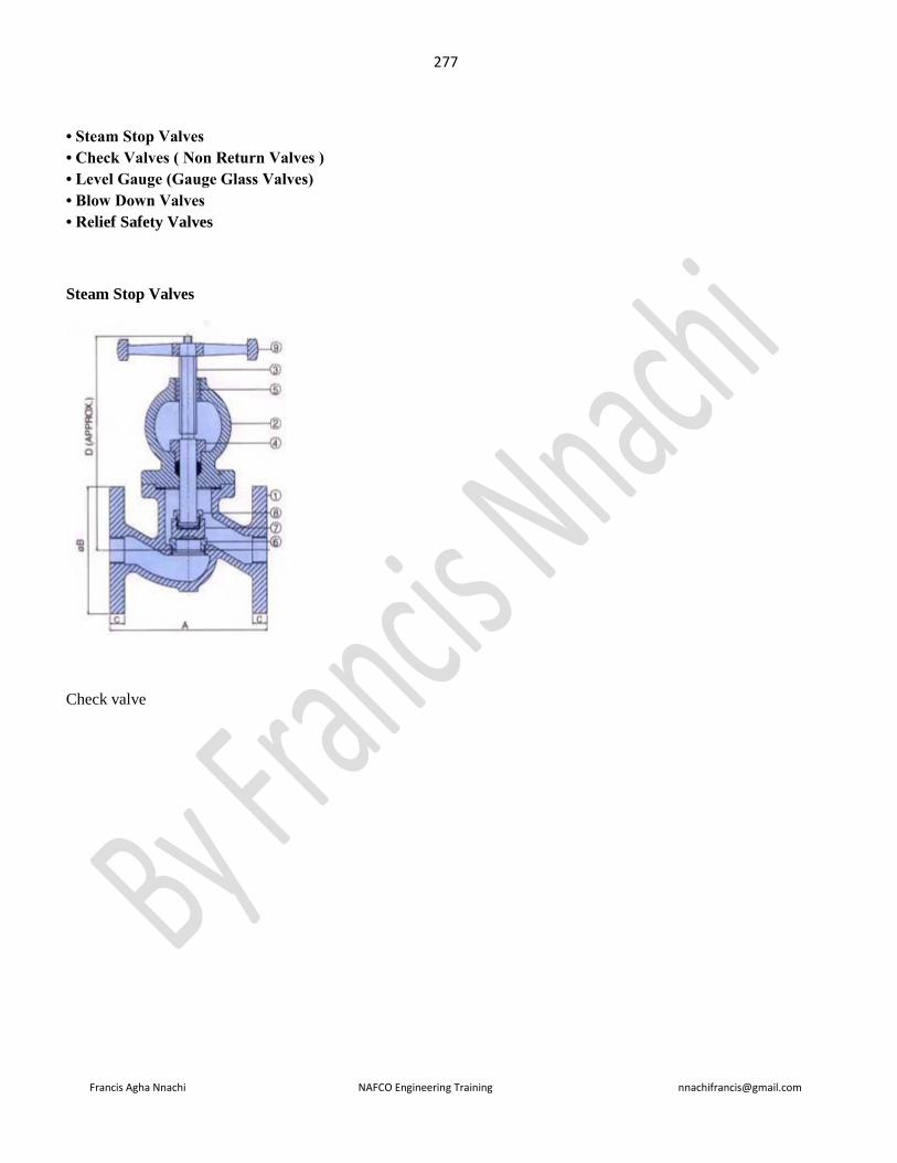
277
Francis Agha Nnachi NAFCO Engineering Training [email protected]
• Steam Stop Valves
• Check Valves ( Non Return Valves )
• Level Gauge (Gauge Glass Valves)
• Blow Down Valves
• Relief Safety Valves
Steam Stop Valves
Check valve
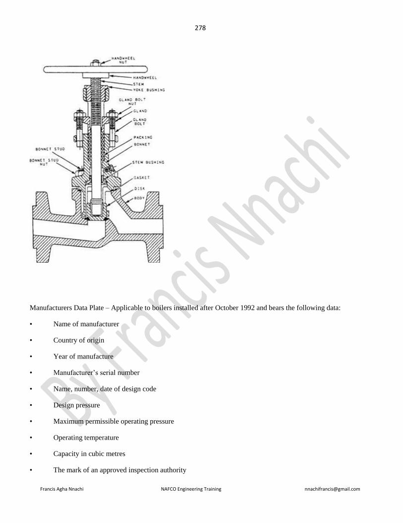
278
Francis Agha Nnachi NAFCO Engineering Training [email protected]
Manufacturers Data Plate – Applicable to boilers installed after October 1992 and bears the following data:
• Name of manufacturer
• Country of origin
• Year of manufacture
• Manufacturer’s serial number
• Name, number, date of design code
• Design pressure
• Maximum permissible operating pressure
• Operating temperature
• Capacity in cubic metres
• The mark of an approved inspection authority