Embed Size (px)
Citation preview

Application Note
AN2374/DRev. 0, 10/2002
Using the Queued Output Match TPU Function (QOM) with the MPC500 Family
Jeff Loeliger
TECD
F
ree
sca
le S
em
ico
nd
uc
tor,
I
nc
...
This TPU Programming Note is intended to provide simple C interface routines to the queuedoutput match TPU function (QOM). 1 The routines are targeted for the MPC500 family ofdevices, but they should be easy to use with any device that has a TPU.
1 Functional OverviewThe QOM function generates complex pulse trains without CPU intervention using a sequenceof output matches. An output match causes a programmable pin state when a user-definedvalue is matched by the value of one of the internal timebases. QOM generates multiple outputmatches using a queue of offset times and pin responses in parameter RAM. Queue size canvary from application to application. Various modes of queued operation are supported.
2 Detailed DescriptionEntries in the QOM queue (event table) are relative match offsets, not absolute match times.The next match time in a sequence is calculated by adding the next queued offset to the timeof the last match. If the match is the first match in a sequence, the first offset value in the queueis added to a select table reference time.
The reference time from which the first match in a sequence is scheduled can be the immediatevalue of the selected TCR, the time of the last match of a previous sequence, or a timecontained in parameter RAM. Using the time of the last match of a previous sequence as areference allows a series of sequences to be chained together. Using a time value fromparameter RAM allows a chain of output matches to be referenced to a time derived by anotherTPU channel.
Pin response (high or low transition) when a match occurs is fully programmable. Pinresponse is determined by the value of bit 0 in each queue entry.
The function can operate in single-shot mode, in which a sequence of match outputs isgenerated once; in loop mode, in which a sequence of match outputs is generated a specifiednumber of times (1 to 256), or in continuous mode; in which the entire sequence repeats untilthe channel is disabled or the TPU receives a new host service request. Linked operation
1The information in this Programming Note is based on TPUPN01. It is intended tocompliment the information found in that Programming Note.
For More Information On This Product,
Go to: www.freescale.com

QOM C Level API
F
ree
sca
le S
em
ico
nd
uc
tor,
I
Freescale Semiconductor, Inc.n
c..
.
allows the function to be triggered by a link from another TPU channel. All loop modes can be used inconjunction with linked operation.
In single-shot mode and in loop mode, the event time of the last match in the queue is written back intoparameter RAM for the CPU to access. Three host service states allow the function to be initiated with theoutput pin high, low, or with no change in state.
If adjacent queue offset values are programmed for the same pin response, duration of an output event caneffectively be extended beyond the normal 0x8000 TCR-count limit imposed by the TPU greater-than-or-equal-to comparator.
2.1 QOM C Level APIRather then controlling the TPU registers directly the QOM routine in this TPU Programming Note may beused to provide a simple and easy interface. There is 1 routine for controlling the QOM function in 2 files(tpu_qom.h and tpu_qom.c). The tpu_qom.h file should be included in any files that use the routine. Thisfiles contains the function prototypes and useful #defines. The routine in tpu_qom.c will be examined indetail:
• Initialization Function:
— void tpu_qom_init(struct TPU3_tag *tpu, UINT8 channel, UINT8 priority,UINT8 mode, UINT8 timebase, UINT8 pin, UINT8 first_match, UINT8 loop, UINT8 ref, UINT8 events, union event_tag event[]);
• General TPU Functions (defined in mpc500_util.h):
— void tpu_enable(struct TPU3_tag *tpu, UINT8 channel, UINT8 priority);
This can also be used to change the priority.— void tpu_disable (struct TPU3_tag *tpu, UINT8 channel);
2.1.1 void tpu_qom_initThis function is used to initialize a channel to run the QOM function. This function has 11 parameters:
• *tpu - This is a pointer to the TPU3 module to use. It is of type TPU3_tag which is defined in m_tpu3.h.
• channel - This is the channel number of the QOM channel.
• priority - This is the priority to the channel. This parameter should be assigned a value of: TPU_PRIORITY_HIGH, TPU_PRIORITY_MIDDLE or TPU_PRIORITY_LOW. The TPU priorities are defined in mpc500_util.h.
• mode – This is the operating mode. This parameter should be assigned a value of: TPU_QOM_SINGLE_SHOT, TPU_QOM_LOOP or TPU_QOM_CONTINUOUS. The modes are defined in tpu_qom.h.
• timebase – This is the timebase that should be used as a reference for all events. This parameter should be assigned a value of: TPU_QOM_TCR1or TPU_QOM_TCR2. The timebases are defined in tpu_qom.h.
• pin – This is the initial state of the output pin. This parameter should be assigned a value of: TPU_QOM_INIT_PIN_NO_CHANGE, TPU_QOM_INIT_PIN_LOW or TPU_QOM_INIT_PIN_HIGH. The pin states are defined in tpu_qom.h.
2 Using the Queued Output Match TPU Function
For More Information On This Product, Go to: www.freescale.com

Example 1
F
ree
sca
le S
em
ico
nd
uc
tor,
I
Freescale Semiconductor, Inc.n
c..
.
• first_match – This is the reference for the first match. This parameter should be assigned a value of: TPU_QOM_IMMEDIATE, TPU_QOM_LAST_EVENT or TPU_QOM_REF. The first match values are defined in tpu_qom.h.
• loop – This is the number of times the offset table should be repeated if the channel is running in loop mode (TPU_QOM_LOOP).
• ref – This is the address of the parameter to use as a reference for the first edge if the function is using a reference (TPU_QOM_REF).
• events – This is the number of events or offsets in the table.
• event[] – This is the table of events or offsets used to define the output signal.
Care should be taken when initializing TPU channels. The TPU’s behavior may be unpredictable if achannel is reconfigured while it is running. The channel should be stopped before it is configured. Settingthe channel’s priority to disabled does this. If the channel is currently being serviced when the priority is setto disable it will continue to service the channel until the state ends. To make sure the channel is not beingservice you need to wait for the longest state execution time after disabling the channel. All channels aredisabled out of reset so the channels can be configured immediately from reset.
The tpu_qom_init function attempts to wait between the disabling of the channels before it starts configuringthem, however the actual execution speed of the code will be depend on the specific system. If you are notconfiguring the channel from reset, then ideally it is best to have the function disabled before calling thisfunction. Using the tpu_disable function in the mpc500_util.c file can disable TPU channels. For example,disabling channel 5 is done like this:
tpu_disable(tpu, 5);
The event array is defined using the event_tag union in tpu_qom.h. The events in the array are composedon an offset and a pin level. The offset is a 15 bit number and has a range of 0 to 0x7FFF. The pin level isdefine as a rising or falling edge. The event value is formed by shifting the offset to the left 1 bit and ORingthe pin value. When using the union you can specify the full 16 bit value directly (event.p) or you can specifythe 2 parts separately (event.offset and event.pin). The event array can be generated by the program, asshown in example 1 or it can be generated at compile time and stored in Flash, as shown in example 4.
3 Queue Output Match ExamplesThe QOM function is capable of generating complex output waveforms. The following examples give anindication of the capabilities of the function. Each example includes a description of the example, a Cprogram to configure the channel and a diagram of the output waveform. Unless otherwise noted, allexamples use TPU A channel 4. The examples are simplified to illustrate certain features of the function -long match times are not split into even segments, and the interrupt service request that is always generatedafter initialization and links from other channels is not shown.
The examples are the same as in TPUPN01, but have been ported to the new C API interface.
3.1 Example 1
3.1.1 DescriptionSingle-shot mode generates a single falling edge with no forced start condition and with a delay of 0x500TCR2 counts from an immediate reference.
Using the Queued Output Match TPU Function
For More Information On This Product, Go to: www.freescale.com

Example 1
F
ree
sca
le S
em
ico
nd
uc
tor,
I
Freescale Semiconductor, Inc.n
c..
.
3.1.2 Program***********************************************************************************************/
/* FILE NAME: tpu_qom_example1.c COPYRIGHT (c) 2002 */
/* VERSION: 1.0 All Rights Reserved */
/* */
/* DESCRIPTION: This sample program shows a simple example of a program */
/* that uses the QOM API to control an output pin. */
/* The program is targeted for the MPC555 but should work on any MPC500 */
/* device with a TPU. For other devices the setup routines will also need */
/* to be changed. */
/*========================================================================*/
/* HISTORY ORIGINAL AUTHOR: Jeff Loeliger */
/* REV AUTHOR DATE DESCRIPTION OF CHANGE */
/* --- ----------- --------- --------------------- */
/* 1.0 J. Loeliger 21/Sep/02 Initial version of function. */
/**************************************************************************/
#include "mpc555.h" /* Define all of the MPC555 registers, this needs to */
/* changed if other MPC500 devices are used. */
#include "mpc500.c" /* Configuration routines for MPC555 EVB, will need */
/* to be changed if other hardware is used. */
#include "mpc500_util.h" /* Utility routines for using MPC500 devices */
#include "tpu_qom.h" /* TPU qom functions */
union event_tag event[0];
void main ()
{
struct TPU3_tag *tpua = &TPU_A; /* pointer for TPU routines */
setup_mpc500(40); /*Setup device and programm PLL to 40MHz*/
4 Using the Queued Output Match TPU Function
For More Information On This Product, Go to: www.freescale.com

Example 2
F
ree
sca
le S
em
ico
nd
uc
tor,
I
Freescale Semiconductor, Inc.n
c..
.
/********************************************************************/
/* Define output: single falling edge. */
/* channel: 4 */
/* mode: single shot */
/* timebase: TCR2 */
/* initial pin state: no change */
/* first match: immediate */
/* loop count: NA (not used in single shot mode) */
/* reference parameter: NA (not used in immediate first match mode) */
/* number of events: 1 */
/* event 1: 0x500 counts then drive pin low. */
/********************************************************************/
event[0].b.offset = 0x500;
event[0].b.pin = TPU_QOM_FALLING_EDGE;
tpu_qom_init(tpua, 4, TPU_PRIORITY_HIGH, TPU_QOM_SINGLE_SHOT,\
TPU_QOM_TCR2, TPU_QOM_INIT_PIN_NO_CHANGE, TPU_QOM_IMMEDIATE,\
0, 0, 1, event);
}
3.2 Example 2
3.2.1 DescriptionLoop mode generates two active-high pulses with a duration of 0xE000 TCR1 clocks, separated by a 0x400TCR1 clock delay. It starts 0x400 clocks after an immediate reference. Loop mode uses two consecutivequeue entries programmed for the same pin response to produce a match time greater than 0x8000 TCRclocks.
The event table is built by defining each offset and pin state separately in the main program.
Using the Queued Output Match TPU Function
For More Information On This Product, Go to: www.freescale.com

Example 2
F
ree
sca
le S
em
ico
nd
uc
tor,
I
Freescale Semiconductor, Inc.n
c..
.
3.2.2 Program/**************************************************************************/
/* FILE NAME: tpu_qom_example2.c COPYRIGHT (c) 2002 */
/* VERSION: 1.0 All Rights Reserved */
/* */
/* DESCRIPTION: This sample program shows a simple example of a program */
/* that uses the QOM API to control an output pin. */
/* The program is targeted for the MPC555 but should work on any MPC500 */
/* device with a TPU. For other devices the setup routines will also need */
/* to be changed. */
/*========================================================================*/
/* HISTORY ORIGINAL AUTHOR: Jeff Loeliger */
/* REV AUTHOR DATE DESCRIPTION OF CHANGE */
/* --- ----------- --------- --------------------- */
/* 1.0 J. Loeliger 27/Sep/02 Initial version of function. */
/**************************************************************************/
#include "mpc555.h" /* Define all of the MPC555 registers, this needs to */
/* changed if other MPC500 devices are used. */
#include "mpc500.c" /* Configuration routines for MPC555 EVB, will need */
/* to be changed if other hardware is used. */
#include "mpc500_util.h" /* Utility routines for using MPC500 devices */
#include "tpu_qom.h" /* TPU qom functions */
union event_tag event[2]; /* 3 events */
void main ()
{
struct TPU3_tag *tpua = &TPU_A; /* pointer for TPU routines */
setup_mpc500(40); /*Setup device and programm PLL to 40MHz*/
/********************************************************************/
/* Define output: 2 active high pulses. */
/* channel: 4 */
/* mode: loop */
/* timebase: TCR1 */
/* initial pin state: low */
/* first match: immediate */
/* loop count: 2 */
6 Using the Queued Output Match TPU Function
For More Information On This Product, Go to: www.freescale.com

Example 3
F
ree
sca
le S
em
ico
nd
uc
tor,
I
Freescale Semiconductor, Inc.n
c..
.
/* reference parameter: NA (not used in immediate first match mode) */
/* number of events: 3 */
/* event 1: 0x400 counts then drive pin high. */
/* event 2: 0x7FFF counts then drive pin high. */
/* event 3: 0x6001 counts then drive pin low. */
/********************************************************************/
event[0].b.offset = 0x400;
event[0].b.pin = TPU_QOM_RISING_EDGE;
event[1].b.offset = 0x7FFF;
event[1].b.pin = TPU_QOM_RISING_EDGE;
event[2].b.offset = 0x6001;
event[3].b.pin = TPU_QOM_FALLING_EDGE;
tpu_qom_init(tpua, 4, TPU_PRIORITY_HIGH, TPU_QOM_LOOP,\
TPU_QOM_TCR1, TPU_QOM_INIT_PIN_LOW, TPU_QOM_IMMEDIATE,\
2, 0, 3, event);
}
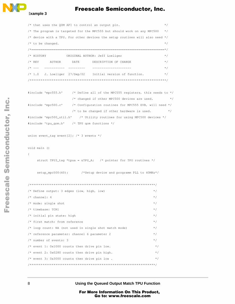
3.3 Example 3
3.3.1 DescriptionSingle-shot mode generates three edges (low, high, low) from a high start. It is referenced to a timecontained in parameter 2 of channel 6. The first edge occurs 0x1000 TCR1 clocks after reference, the secondedge occurs 0x280 clocks after the first, and the third edge occurs 0x3000 clocks after the second.
3.3.2 Program/**************************************************************************/
/* FILE NAME: tpu_qom_example3.c COPYRIGHT (c) 2002 */
/* VERSION: 1.0 All Rights Reserved */
/* */
/* DESCRIPTION: This sample program shows a simple example of a program */
Using the Queued Output Match TPU Function
For More Information On This Product, Go to: www.freescale.com
Example 3
F
ree
sca
le S
em
ico
nd
uc
tor,
I
Freescale Semiconductor, Inc.n
c..
.
/* that uses the QOM API to control an output pin. */
/* The program is targeted for the MPC555 but should work on any MPC500 */
/* device with a TPU. For other devices the setup routines will also need */
/* to be changed. */
/*========================================================================*/
/* HISTORY ORIGINAL AUTHOR: Jeff Loeliger */
/* REV AUTHOR DATE DESCRIPTION OF CHANGE */
/* --- ----------- --------- --------------------- */
/* 1.0 J. Loeliger 27/Sep/02 Initial version of function. */
/**************************************************************************/
#include "mpc555.h" /* Define all of the MPC555 registers, this needs to */
/* changed if other MPC500 devices are used. */
#include "mpc500.c" /* Configuration routines for MPC555 EVB, will need */
/* to be changed if other hardware is used. */
#include "mpc500_util.h" /* Utility routines for using MPC500 devices */
#include "tpu_qom.h" /* TPU qom functions */
union event_tag event[2]; /* 3 events */
void main ()
{
struct TPU3_tag *tpua = &TPU_A; /* pointer for TPU routines */
setup_mpc500(40); /*Setup device and programm PLL to 40MHz*/
/********************************************************************/
/* Define output: 3 edges (low, high, low) */
/* channel: 4 */
/* mode: single shot */
/* timebase: TCR1 */
/* initial pin state: high */
/* first match: from reference */
/* loop count: NA (not used in single shot match mode) */
/* reference parameter: channel 6 parameter 2 */
/* number of events: 3 */
/* event 1: 0x1000 counts then drive pin low. */
/* event 2: 0x0280 counts then drive pin high. */
/* event 3: 0x3000 counts then drive pin low . */
/********************************************************************/
8 Using the Queued Output Match TPU Function
For More Information On This Product, Go to: www.freescale.com

Example 4
F
ree
sca
le S
em
ico
nd
uc
tor,
I
Freescale Semiconductor, Inc.n
c..
.
event[0].p = (0x1000 << 1) + TPU_QOM_FALLING_EDGE;
event[1].p = (0x0280 << 1) + TPU_QOM_RISING_EDGE;
event[2].p = (0x3000 << 1) + TPU_QOM_FALLING_EDGE;
tpu_qom_init(tpua, 4, TPU_PRIORITY_HIGH, TPU_QOM_SINGLE_SHOT,\
TPU_QOM_TCR1, TPU_QOM_INIT_PIN_HIGH, TPU_QOM_REF,\
0, 0x62, 3, event);
}
3.4 Example 4
3.4.1 DescriptionContinuous mode generates active-high pulses with a high time of 0x5100 TCR2 counts separated by a lowtime of 0x2000 counts. It can effectively generate a PWM waveform if the offsets are varied.
The event table is defined as a constant so that it can be stored in Flash. The values in the table are calculatedduring compile.
3.4.2 Program/**************************************************************************/
/* FILE NAME: tpu_qom_example4.c COPYRIGHT (c) 2002 */
/* VERSION: 1.0 All Rights Reserved */
/* */
/* DESCRIPTION: This sample program shows a simple example of a program */
/* that uses the QOM API to control an output pin. */
/* The program is targeted for the MPC555 but should work on any MPC500 */
/* device with a TPU. For other devices the setup routines will also need */
/* to be changed. */
/*========================================================================*/
/* HISTORY ORIGINAL AUTHOR: Jeff Loeliger */
/* REV AUTHOR DATE DESCRIPTION OF CHANGE */
/* --- ----------- --------- --------------------- */
/* 1.0 J. Loeliger 27/Sep/02 Initial version of function. */
/**************************************************************************/
Using the Queued Output Match TPU Function
For More Information On This Product, Go to: www.freescale.com

Example 4
F
ree
sca
le S
em
ico
nd
uc
tor,
I
Freescale Semiconductor, Inc.n
c..
.
#include "mpc555.h" /* Define all of the MPC555 registers, this needs to */
/* changed if other MPC500 devices are used. */
#include "mpc500.c" /* Configuration routines for MPC555 EVB, will need */
/* to be changed if other hardware is used. */
#include "mpc500_util.h" /* Utility routines for using MPC500 devices */
#include "tpu_qom.h" /* TPU qom functions */
/* 2 constant events that can be put into ROM/FLASH*/
const union event_tag event[2] = {(0x2000 << 1) + TPU_QOM_RISING_EDGE,\
(0x5100 << 1) + TPU_QOM_FALLING_EDGE};
void main ()
{
struct TPU3_tag *tpua = &TPU_A; /* pointer for TPU routines */
setup_mpc500(40); /*Setup device and programm PLL to 40MHz*/
/********************************************************************/
/* Define output: PWM style output signal */
/* channel: 4 */
/* mode: continuous */
/* timebase: TCR2 */
/* initial pin state: low */
/* first match: immediate */
/* loop count: NA (not used in continuous mode) */
/* reference parameter: NA (not used in immediate first match mode) */
/* number of events: 2 */
/* event 1: 0x2000 counts then drive pin high. */
/* event 2: 0x5100 counts then drive pin low. */
/********************************************************************/
tpu_qom_init(tpua, 4, TPU_PRIORITY_HIGH, TPU_QOM_CONTINUOUS,\
TPU_QOM_TCR2, TPU_QOM_INIT_PIN_LOW, TPU_QOM_IMMEDIATE,\
0, 0, 2, (void *)event);
}
10 Using the Queued Output Match TPU Function
For More Information On This Product, Go to: www.freescale.com

Example 5
F
ree
sca
le S
em
ico
nd
uc
tor,
I
Freescale Semiconductor, Inc.n
c..
.
3.5 Example 5
3.5.1 DescriptionLinked single-shot operation generates a single long pulse of 0x15000 TCR1 counts duration, 0x500 countsafter a reference time contained in parameter 2 of channel 15. The Initial pin condition remains the same asa previous condition. Linked single-shot uses three consecutive queue entries programmed for the same pinresponse to produce a match time greater than 0x8000 TCR clocks.
3.5.2 Program/**************************************************************************/
/* FILE NAME: tpu_qom_example5.c COPYRIGHT (c) 2002 */
/* VERSION: 1.0 All Rights Reserved */
/* */
/* DESCRIPTION: This sample program shows a simple example of a program */
/* that uses the QOM API to control an output pin. */
/* The program is targeted for the MPC555 but should work on any MPC500 */
/* device with a TPU. For other devices the setup routines will also need */
/* to be changed. */
/*========================================================================*/
/* HISTORY ORIGINAL AUTHOR: Jeff Loeliger */
/* REV AUTHOR DATE DESCRIPTION OF CHANGE */
/* --- ----------- --------- --------------------- */
/* 1.0 J. Loeliger 30/Sep/02 Initial version of function. */
/**************************************************************************/
#include "mpc555.h" /* Define all of the MPC555 registers, this needs to */
/* changed if other MPC500 devices are used. */
#include "mpc500.c" /* Configuration routines for MPC555 EVB, will need */
/* to be changed if other hardware is used. */
#include "mpc500_util.h" /* Utility routines for using MPC500 devices */
#include "tpu_qom.h" /* TPU qom functions */
/* 4 constant events that can be put into ROM/FLASH*/
const union event_tag event[4] = {(0x0500 << 1) + TPU_QOM_RISING_EDGE,\
(0x7FFF << 1) + TPU_QOM_RISING_EDGE,\
Using the Queued Output Match TPU Function
For More Information On This Product, Go to: www.freescale.com

Example 6
F
ree
sca
le S
em
ico
nd
uc
tor,
I
Freescale Semiconductor, Inc.n
c..
.
(0x7FFF << 1) + TPU_QOM_RISING_EDGE,\
(0x5002 << 1) + TPU_QOM_FALLING_EDGE};
void main ()
{
struct TPU3_tag *tpua = &TPU_A; /* pointer for TPU routines */
setup_mpc500(40); /*Setup device and program PLL to 40MHz*/
/********************************************************************/
/* Define output: linked single shot of long pulse */
/* channel: 4 */
/* mode: single shot */
/* timebase: TCR1 */
/* initial pin state: no change */
/* first match: reference */
/* loop count: NA (not used in single shot match mode) */
/* reference parameter: channel 15 parameter 2 */
/* number of events: 4 */
/* event 1: 0x0500 counts then drive pin high. */
/* event 2: 0x7FFF counts then drive pin high. */
/* event 3: 0x7FFF counts then drive pin high. */
/* event 4: 0x5002 counts then drive pin low. */
/********************************************************************/
tpu_qom_init(tpua, 4, TPU_PRIORITY_HIGH, TPU_QOM_SINGLE_SHOT,\
TPU_QOM_TCR1, TPU_QOM_INIT_PIN_NO_CHANGE, TPU_QOM_REF,\
0, 0xf2, 4, (void *)event);
}
3.6 Example 6
3.6.1 DescriptionContinuous mode shows a special case where channel 15 is not used and channel 14 uses channel 14 and 15parameter RAM. TCR1 is used as timebase.
12 Using the Queued Output Match TPU Function
For More Information On This Product, Go to: www.freescale.com

Example 6
F
ree
sca
le S
em
ico
nd
uc
tor,
I
Freescale Semiconductor, Inc.n
c..
.
3.6.2 Program/**************************************************************************/
/* FILE NAME: tpu_qom_example6.c COPYRIGHT (c) 2002 */
/* VERSION: 1.0 All Rights Reserved */
/* */
/* DESCRIPTION: This sample program shows a simple example of a program */
/* that uses the QOM API to control an output pin. */
/* The program is targeted for the MPC555 but should work on any MPC500 */
/* device with a TPU. For other devices the setup routines will also need */
/* to be changed. */
/*========================================================================*/
/* HISTORY ORIGINAL AUTHOR: Jeff Loeliger */
/* REV AUTHOR DATE DESCRIPTION OF CHANGE */
/* --- ----------- --------- --------------------- */
/* 1.0 J. Loeliger 30/Sep/02 Initial version of function. */
/**************************************************************************/
#include "mpc555.h" /* Define all of the MPC555 registers, this needs to */
/* changed if other MPC500 devices are used. */
#include "mpc500.c" /* Configuration routines for MPC555 EVB, will need */
/* to be changed if other hardware is used. */
#include "mpc500_util.h" /* Utility routines for using MPC500 devices */
#include "tpu_qom.h" /* TPU qom functions */
/* 14 constant events that can be put into ROM/FLASH*/
const union event_tag event[14] = {(0x0100 << 1) + TPU_QOM_FALLING_EDGE,\
(0x0200 << 1) + TPU_QOM_RISING_EDGE,\
(0x0300 << 1) + TPU_QOM_FALLING_EDGE,\
(0x0200 << 1) + TPU_QOM_RISING_EDGE,\
(0x0100 << 1) + TPU_QOM_FALLING_EDGE,\
(0x0200 << 1) + TPU_QOM_RISING_EDGE,\
(0x0200 << 1) + TPU_QOM_FALLING_EDGE,\
Using the Queued Output Match TPU Function
For More Information On This Product, Go to: www.freescale.com

Example 6
F
ree
sca
le S
em
ico
nd
uc
tor,
I
Freescale Semiconductor, Inc.n
c..
.
(0x0200 << 1) + TPU_QOM_RISING_EDGE,\
(0x0100 << 1) + TPU_QOM_FALLING_EDGE,\
(0x0100 << 1) + TPU_QOM_RISING_EDGE,\
(0x0100 << 1) + TPU_QOM_FALLING_EDGE,\
(0x0100 << 1) + TPU_QOM_RISING_EDGE,\
(0x0100 << 1) + TPU_QOM_FALLING_EDGE,\
(0x0200 << 1) + TPU_QOM_RISING_EDGE};
void main ()
{
struct TPU3_tag *tpua = &TPU_A; /* pointer for TPU routines */
setup_mpc500(40); /*Setup device and program PLL to 40MHz*/
/********************************************************************/
/* Define output: continuous complex output waveform */
/* channel: 14 */
/* mode: continuous */
/* timebase: TCR1 */
/* initial pin state: high */
/* first match: immediate */
/* loop count: NA (not used in single shot match mode) */
/* reference parameter: NA (not used in immediate first match mode) */
/* number of events: 14 */
/* event 1: 0x0100 counts then drive pin high. */
/* event 2: 0x0200 counts then drive pin high. */
/* event 3: 0x0300 counts then drive pin high. */
/* event 4: 0x0200 counts then drive pin low. */
/* event 5: 0x0100 counts then drive pin high. */
/* event 6: 0x0200 counts then drive pin high. */
/* event 7: 0x0200 counts then drive pin high. */
/* event 8: 0x0200 counts then drive pin low. */
/* event 9: 0x0100 counts then drive pin high. */
/* event 10: 0x0100 counts then drive pin high. */
/* event 11: 0x0100 counts then drive pin high. */
/* event 12: 0x0100 counts then drive pin low. */
/* event 13: 0x0100 counts then drive pin high. */
/* event 14: 0x0200 counts then drive pin high. */
/********************************************************************/
tpu_qom_init(tpua, 14, TPU_PRIORITY_HIGH, TPU_QOM_CONTINUOUS, \
14 Using the Queued Output Match TPU Function
For More Information On This Product, Go to: www.freescale.com

Example 6
F
ree
sca
le S
em
ico
nd
uc
tor,
I
Freescale Semiconductor, Inc.n
c..
.
TPU_QOM_TCR1, TPU_QOM_INIT_PIN_HIGH, TPU_QOM_IMMEDIATE,\
0, 0, 14, (void *)event);
}
4 Function State TimingWhen calculating the worst-case latency for the TPU the execution time of each state of the TPU is need.The state timings for the QOM function are shown in Table 1. The states used by the C interface functionsare shown in Table 2. State S5 is entered when there is a match and S4 is entered when there is a link sentto the channel.
NOTE: Execution times do not include the time slot transition time (TST= 10 or 14 CPU clocks)
5 Function Code SizeTotal TPU function code size determines what combination of functions can fit into a given ROM oremulation DPTRAM memory microcode space. The QOM function code size is:
41 µ instructions + 8 entries = 49 long words
Table 1. QOM Function—State Timing
State Number & Name Max CPU Clock Cycles RAM accesses by TPU
S1 QOM_HI Linked operation Normal modes
1248
27
S2 QOM_LO Linked operation Normal modes
1450
27
S3 QOM_NC Linked operation Normal modes
1450
27
S4 QOM_LNK 36 6
S5 QOM_M Single Shot Loop Continuous
223022
444
Table 2. QOM Function—State Usage
QOM API function State uses
tpu_qom_init S1, S2 or S3
Using the Queued Output Match TPU Function
For More Information On This Product, Go to: www.freescale.com

Performance
F
ree
sca
le S
em
ico
nd
uc
tor,
I
Freescale Semiconductor, Inc.n
c..
.
6 Notes on the Performance and Use of the QOM Function
6.1 PerformanceLike all TPU functions, QOM function performance in an application is to some extent dependent upon theservice time (latency) of other active TPU channels. This is due to the operational nature of the scheduler.When a single QOM channel is in use and no other TPU channels are active, the minimum time betweensuccessive matches is 36 CPU clock cycles in single shot and continuous modes and 44 CPU clocks in loopmode. When more TPU channels are active, performance decreases. However, worst-case latency in anyTPU application can be closely estimated. To analyze the performance of an application that appears toapproach the limits of the TPU, use the guidelines given in the TPU reference manual and the informationin Table 1.
6.2 Using QOM for Pulse Width ModulationThe QOM function can be used to generate a pulse-width modulated output in systems that do not have adedicated TPU PWM function. A PWM output is generated using continuous mode and two match offsets.One offset is configured to generate a rising edge, and the other is configured to generate a falling edge. Theoffset that generates the rising edge is the low-time parameter and the offset that generates the falling edgeis the high-time parameter. Modulation is achieved by varying the offset values in the queue. Example 4shows PWM setup and output. 100% and 0% duty cycles are easily obtained by configuring both offsets togenerate either a rising edge (100% duty cycle) or a falling edge (0%).
6.2.1 Initialization to First Match DelayWhen an immediate TCR value is used as a reference for the first queued match time, there is a delaybetween the time that the channel pin is initialized and the time that the TCR is read. This delay is causedby TPU code execution during states 1, 2 and 3. The delay causes the period between pin initialization andthe output caused by the first match event to be longer than the period specified by the offset value in thefirst queue entry. The additional time is equivalent to 16 CPU clocks when TCR1 is the time base and 18CPU clocks when TCR2 is the time base. If the duration of the initial pin state is critical, it may be necessaryto take this additional time into account when the first offset value is specified.
6.2.2 Linked OperationDuring linked operation, if an additional link is received after the function has started scheduling matches,state 5 (QOM_LNK) is re-executed. Executing state 5 again causes OFF_PTR to be reset to the start of thequeue, and thus restarts the match sequence. When this happens, a new scheduled match replaces anypending match. If an additional link is received while a loop is executing, the sequence repeats, butLOOP_CNT is not reset to the initial value. When a complete match sequence has been executed and thefunction has stopped, additional link requests are ignored.
6.2.3 Changing ModesIn order to change modes on the channel while it is still running, the channel must first be disabled. This canbe done using the tpu_disable functio in tpu_util.c.
16 Using the Queued Output Match TPU Function
For More Information On This Product, Go to: www.freescale.com

Listing 1
F
ree
sca
le S
em
ico
nd
uc
tor,
I
Freescale Semiconductor, Inc.n
c..
.
6.2.4 Using a Reference Address for the First MatchAlthough the examples in this note that use a reference time pointed to by REF_ADDR have reference timesthat occur before the HSR or a link that initiates the function, this need not be the case. A first match isscheduled correctly when the HSR or link occurs before the reference time, as shown in Figure 1.
Figure 1. First Match with HSR Prior to Reference Time
6.2.5 Long Match TimesThe QOM function can produce long apparent match times by using two or more queue entries programmedfor the same pin response. This technique can extend a pin state change well beyond the normal limit of0x8000 TCR counts. Because very short match times can have an adverse effect on overall TPUperformance, it is best to split a long match time into even segments rather than following a very longsegment with a very short segment. For example, if a total match time of 0x8100 counts is required, use two0x4080-count match times rather than one match time of 0x7FFF counts and another of 0x101 counts.
6.3 Listing 1/**************************************************************************/
/* FILE NAME: tpu_qom.h COPYRIGHT (c) 2002 */
/* VERSION: 1.0 All Rights Reserved */
/* */
/* DESCRIPTION: This file defines the interface to the TPU QOM function */
/* and provides useful #defines. */
/* */
/*========================================================================*/
/* HISTORY ORIGINAL AUTHOR: Jeff Loeliger */
/* REV AUTHOR DATE DESCRIPTION OF CHANGE */
/* --- ----------- --------- --------------------- */
/* 1.0 J. Loeliger 21/Sept/02 Initial version of function. */
/**************************************************************************/
#ifndef _TPU_QOM_H
#define _TPU_QOM_H
#include "m_common.h"
#include "m_tpu3.h"
Using the Queued Output Match TPU Function
For More Information On This Product, Go to: www.freescale.com

Listing 1
F
ree
sca
le S
em
ico
nd
uc
tor,
I
Freescale Semiconductor, Inc.n
c..
.
union event_tag {
UINT16 p;
struct {
UINT16 offset:15;
UINT16 pin:1;
} b;
};
/* Define edges for action after delay */
#define TPU_QOM_FALLING_EDGE 0
#define TPU_QOM_RISING_EDGE 1
/* Define operating modes (also HSQ values) */
#define TPU_QOM_SINGLE_SHOT 0
#define TPU_QOM_LOOP 1
#define TPU_QOM_CONTINUOUS 2
/* Define timebases */
#define TPU_QOM_TCR1 0
#define TPU_QOM_TCR2 1
/* Define initial pin state (also HSR values) */
#define TPU_QOM_INIT_PIN_NO_CHANGE 1
#define TPU_QOM_INIT_PIN_LOW 2
#define TPU_QOM_INIT_PIN_HIGH 3
/* Define reference for first match */
#define TPU_QOM_IMMEDIATE 0
#define TPU_QOM_LAST_EVENT 1
#define TPU_QOM_REF 2
/* TPU QOM function prototypes */
void tpu_qom_init(struct TPU3_tag *tpu, UINT8 channel, UINT8 priority,\
UINT8 mode, UINT8 timebase, UINT8 pin, UINT8 first_match, UINT8 loop, \
UINT8 ref, UINT8 events, union event_tag event[]);
#endif /* ifndef _TPU_QOM_H */
18 Using the Queued Output Match TPU Function
For More Information On This Product, Go to: www.freescale.com

Listing 2
F
ree
sca
le S
em
ico
nd
uc
tor,
I
Freescale Semiconductor, Inc.n
c..
.
6.4 Listing 2/**************************************************************************/
/* FILE NAME: tpu_qom.c COPYRIGHT (c) 2002 */
/* VERSION: 1.0 All Rights Reserved */
/* */
/* DESCRIPTION: This file contains the TPU QOM function. This function */
/* allow you to completely control TPU channels running the QOM function. */
/* They provide a simple interface requiring the minimum amount of */
/* configuration by the user. */
/*========================================================================*/
/* HISTORY ORIGINAL AUTHOR: Jeff Loeliger */
/* REV AUTHOR DATE DESCRIPTION OF CHANGE */
/* --- ----------- --------- --------------------- */
/* 1.0 J. Loeliger 21/Sep/02 Initial version of function. */
/**************************************************************************/
#include "tpu_qom.h"
#include "mpc500_util.h"
/*******************************************************************************
FUNCTION : tpu_qom_init
PURPOSE : To initialize a channel to run the QOM function in output mode.
INPUTS NOTES : This function has 4 parameters:
*tpu - This is a pointer to the TPU3 module to use. It is of
type TPU3_tag which is defined in m_tpu3.h
channel - This is the channel number of the primary QDEC
channel.
priority - This is the priority to assign to both channels.
This parameter should be assigned a value of:
TPU_PRIORITY_HIGH, TPU_PRIORITY_MIDDLE or
TPU_PRIORITY_LOW.
mode - This is the operating mode.
timebase - This is the timebase to reference.
pin - This is the intial pin state.
ref - This is an address reference in ref mode.
loop - This is the loop count in loop mode.
match - reference mode for first match.
events - This is the number of events.
event[] - This is the array of events.
RETURNS NOTES : none
WARNING : The channels must be stopped before it is reconfigured. The
Using the Queued Output Match TPU Function
For More Information On This Product, Go to: www.freescale.com

Listing 2
F
ree
sca
le S
em
ico
nd
uc
tor,
I
Freescale Semiconductor, Inc.n
c..
.
function disables the channels but if they were currently
being serviced it would continue. The delay for assigning the
pram pointer may to enough but depends on system loading.
*******************************************************************************/
void tpu_qom_init(struct TPU3_tag *tpu, UINT8 channel, UINT8 priority,\
UINT8 mode, UINT8 timebase, UINT8 pin, UINT8 first_match, UINT8 loop, \
UINT8 ref, UINT8 events, union event_tag event[])
{
int x,p;
/* disable channel so it can be configured safely */
tpu_disable( tpu, channel);
/* select QOM function for channel */
tpu_func( tpu, channel, TPU_FUNCTION_QOM);
/* Initialize HSQ which determines operating mode */
tpu_hsq(tpu, channel, mode);
/* Configure parameter RAM */
tpu->PARM.R[channel][0] = (((UINT16)ref & 0xfe) << 8) | \
(((UINT16)first_match & 2) << 7) | \
(((channel << 4) + 2 + (events * 2)) & 0xFF) |\
timebase;
if (mode == TPU_QOM_LOOP)
tpu->PARM.R[channel][1] = ((UINT16)loop << 8);
if ((first_match & 1) == 1 )
tpu->PARM.R[channel][1] |= 1;
else
tpu->PARM.R[channel][1] &= 0xFFFE;
/* build event offset and pin state table */
p = 2;
for(x=0 ; x<events ; x++){
tpu->PARM.R[channel][p++] = event[x].p;
if (p == 8){
p = 0;
channel++;
20 Using the Queued Output Match TPU Function
For More Information On This Product, Go to: www.freescale.com

Listing 2
F
ree
sca
le S
em
ico
nd
uc
tor,
I
Freescale Semiconductor, Inc.n
c..
.
}
if (channel == 16)
channel = 0;
}
/* Initialize function with initial pin state */
tpu_hsr(tpu, channel, pin);
/* Enable channel by assigning a priority. */
tpu_enable(tpu, channel, priority);
}
Using the Queued Output Match TPU Function
For More Information On This Product, Go to: www.freescale.com

Listing 2
F
ree
sca
le S
em
ico
nd
uc
tor,
I
Freescale Semiconductor, Inc.n
c..
.
THIS PAGE INTENTIONALLY LEFT BLANK
22 Using the Queued Output Match TPU Function
For More Information On This Product, Go to: www.freescale.com

Listing 2
F
ree
sca
le S
em
ico
nd
uc
tor,
I
Freescale Semiconductor, Inc.n
c..
.
THIS PAGE INTENTIONALLY LEFT BLANK
Using the Queued Output Match TPU Function
For More Information On This Product, Go to: www.freescale.com

AN2374/D
Fre
esc
ale
Se
mic
on
du
cto
r, I
Freescale Semiconductor, Inc.
For More Information On This Product, Go to: www.freescale.com
nc
...