Embed Size (px)
Citation preview
1
Frame Relay
Packet switching system with low overhead Assumes very reliable high-quality
physical network Developed for use in ISDN networks Used widely in a variety of private and
public networks which are not ISDN
2
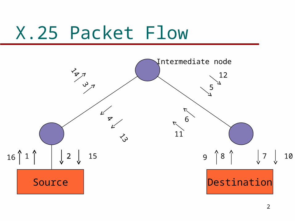
X.25 Packet Flow
Source Destination
216 1 152
143
13
4
12
5
6
11
9 8 107
Intermediate node
3
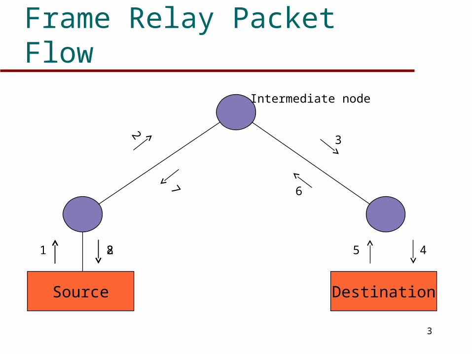
Frame Relay Packet Flow
Source Destination
21 8
2
7
3
6
5 4
Intermediate node
4
Frame Relay
Control Signalling carried on separate logical connection from user data
Multiplexing and switching of logical connections take place at layer 2 not layer 3
No hop-by-hop flow control or error control Protocol functionality at user-network interface
is reduced Large increase in throughput over X.25
5
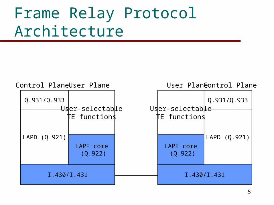
Frame Relay Protocol Architecture
Physical
Q.931/Q.933
LAPD (Q.921)
I.430/I.431
User-selectableTE functions
LAPF core (Q.922)
User PlaneControl Plane
Physical
Q.931/Q.933
LAPD (Q.921)
I.430/I.431
User-selectableTE functions
LAPF core (Q.922)
User Plane Control Plane
6
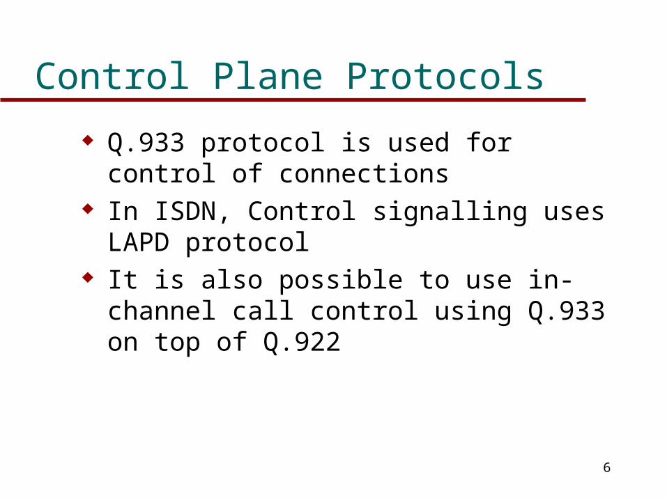
Control Plane Protocols
Q.933 protocol is used for control of connections In ISDN, Control signalling uses LAPD protocol It is also possible to use in-channel call control
using Q.933 on top of Q.922
7
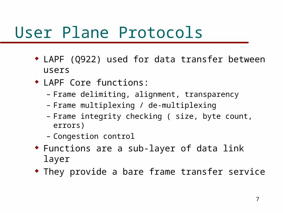
User Plane Protocols
LAPF (Q922) used for data transfer between users LAPF Core functions:
– Frame delimiting, alignment, transparency
– Frame multiplexing / de-multiplexing
– Frame integrity checking ( size, byte count, errors)
– Congestion control
Functions are a sub-layer of data link layer They provide a bare frame transfer service
8
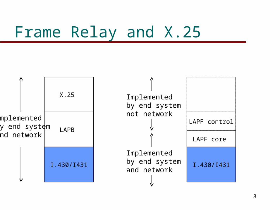
Frame Relay and X.25
LAPB
I.430/I431
X.25
LAPF core
I.430/I431
LAPF controlImplementedby end systemand network
Implementedby end systemnot network
Implementedby end systemand network
9
Frame Relay Call Control
Subscriber must first be connected to a frame handler
This is called an access connection When access connection is made, multiple
logical channels can be multiplexed on the connection
These are called frame relay connections They can be on-demand or semi-permanent
10
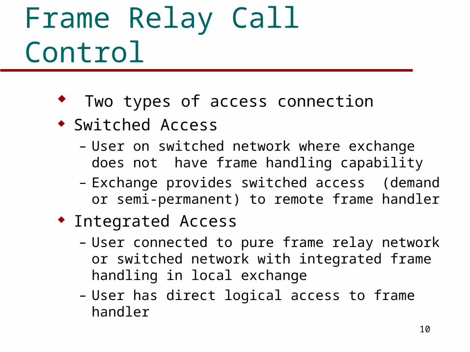
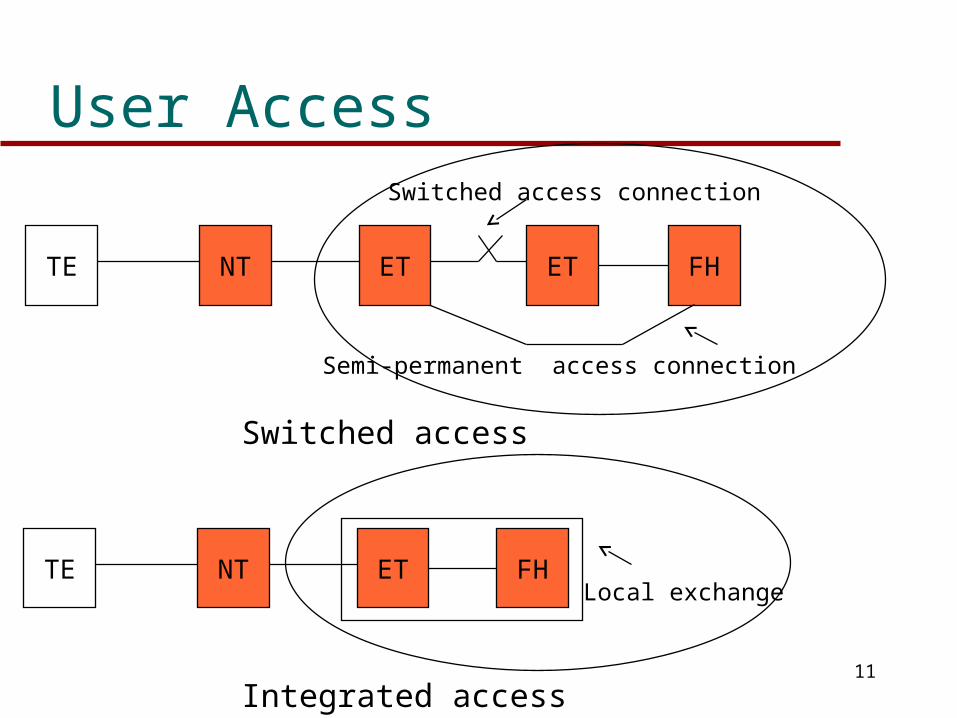
Frame Relay Call Control
Two types of access connection Switched Access
– User on switched network where exchange does not have frame handling capability
– Exchange provides switched access (demand or semi-permanent) to remote frame handler
Integrated Access– User connected to pure frame relay network or
switched network with integrated frame handling in local exchange
– User has direct logical access to frame handler
11
User Access
TE NT FHET ET
Switched access connection
Semi-permanent access connection
Switched access
TE NT FHET
Integrated access
Local exchange
12
Frame Relay Connections
Analogous to virtual circuit in X.25 Can be established when access connection
established to frame handler Multiple connections supported over single
link– Called data link connections
Each connection has a unique Data link connection identifier (DLCI)
13
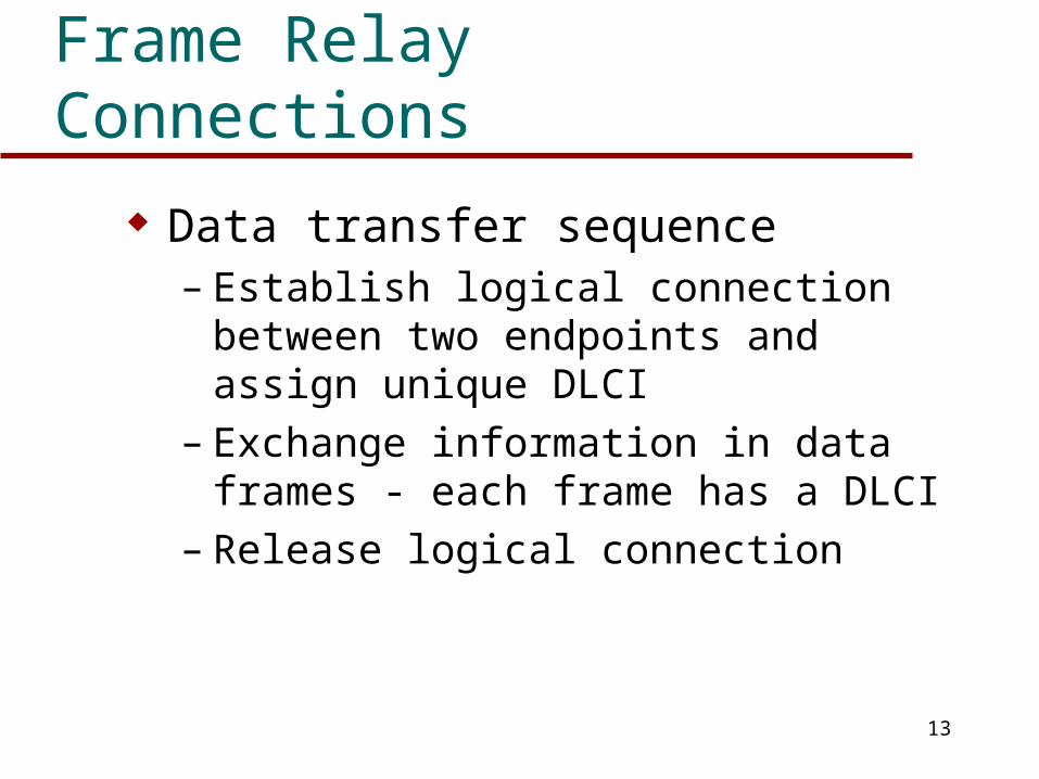
Frame Relay Connections
Data transfer sequence– Establish logical connection between two
endpoints and assign unique DLCI– Exchange information in data frames - each
frame has a DLCI– Release logical connection
14
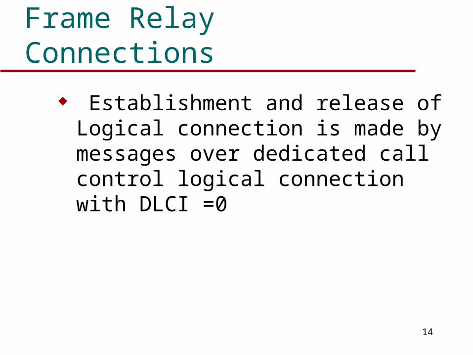
Frame Relay Connections
Establishment and release of Logical connection is made by messages over dedicated call control logical connection with DLCI =0
15
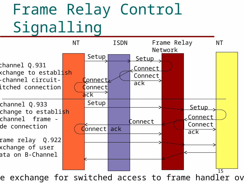
Frame Relay Control Signalling
Message exchange for switched access to frame handler over ISDN
D-channel Q.931 exchange to establish B-channel circuit-switched connection
NT ISDN Frame RelayNetwork
NT
Setup
ConnectConnect ack
Setup
B-channel Q.933exchange to establishB-channel frame -mode connection
Frame relay Q.922exchange of user data on B-Channel
Connect
ConnectConnect ack
ConnectConnect ack
Setup
Connect ack
Setup
16
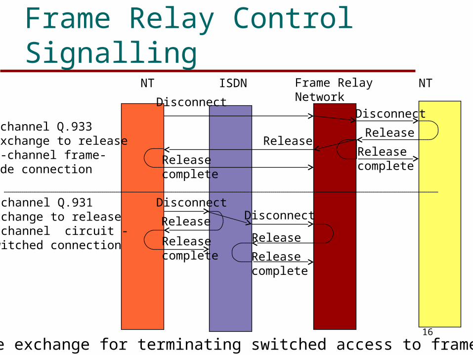
Frame Relay Control Signalling
Message exchange for terminating switched access to frame handler
B-channel Q.933 exchange to release B-channel frame-mode connection
NT ISDN Frame RelayNetwork
NT
D-channel Q.931exchange to releaseB-channel circuit -switched connection
Release
DisconnectDisconnect
Release
ReleasecompleteRelease
complete
Disconnect
Release Disconnect
Releasecomplete
ReleaseReleasecomplete
17
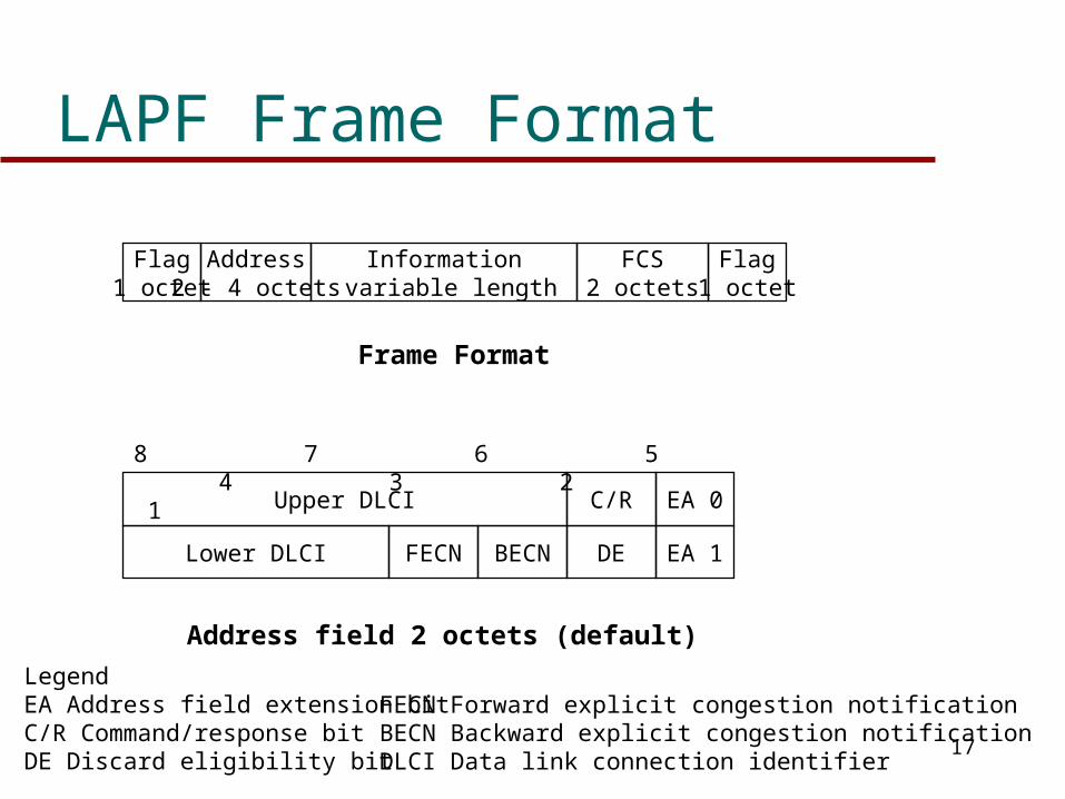
LAPF Frame Format
Flag1 octet
Information variable length
FCS2 octets
Flag1 octet
Frame Format
Address2 - 4 octets
Upper DLCI C/R EA 0
EA 1DEBECNFECNLower DLCI
8 7 6 5 4 3 2 1
Address field 2 octets (default)
LegendEA Address field extension bitC/R Command/response bitDE Discard eligibility bit
FECN Forward explicit congestion notificationBECN Backward explicit congestion notificationDLCI Data link connection identifier
18
LAPF Frame Format
No control field exists in the frame The connection can only carry user data Therefore no in-band signalling exists No error control or flow control exists since
there are no sequence numbers
19
LAPF Frame Format
Address field carries DLCI Address field length may be extended to 2,
3, or 4 octets Length determined by EA bits - default is 2
octets DLCI allows multiple logical connections
to be multiplexed on single channel DLCI can be 10, 17 or 24 bits depending on
address field length
20
Congestion Control
No in-channel control signalling means no sliding window flow control
Congestion control is the joint responsibility of the network and the end-user
Network monitors congestion User controls congestion by limiting flow
of traffic at origin Network discards packets as a last resort
21
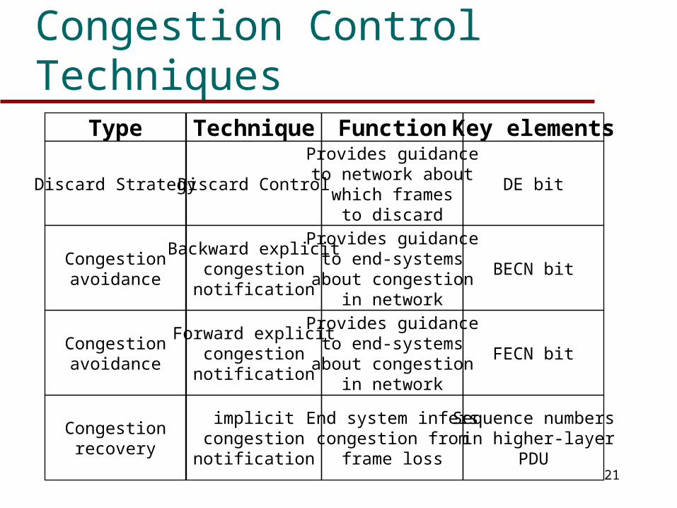
Congestion Control TechniquesFunction Key elements
Provides guidanceto network about
which framesto discard
DE bit
Provides guidanceto end-systems
about congestionin network
BECN bit
Provides guidanceto end-systems
about congestionin network
FECN bit
Technique
Discard Control
Backward explicitcongestionnotification
Forward explicitcongestionnotification
implicitcongestionnotification
Type
Discard Strategy
Congestionavoidance
Congestionavoidance
Congestionrecovery
End system inferscongestion from
frame loss
Sequence numbers in higher-layer
PDU
22
Discard Strategy
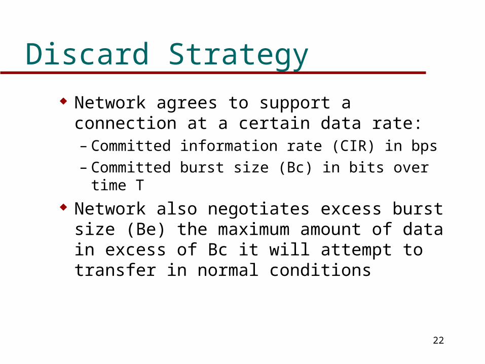
Network agrees to support a connection at a certain data rate:– Committed information rate (CIR) in bps– Committed burst size (Bc) in bits over time T
Network also negotiates excess burst size (Be) the maximum amount of data in excess of Bc it will attempt to transfer in normal conditions
23
Discard Strategy
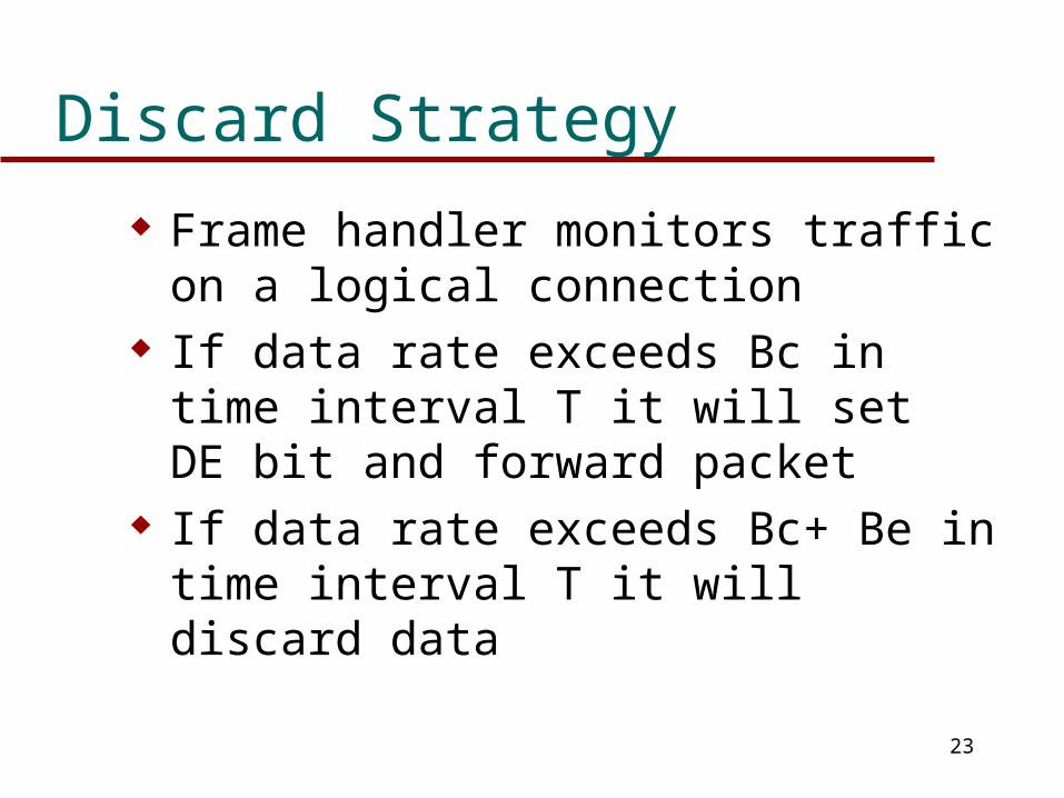
Frame handler monitors traffic on a logical connection
If data rate exceeds Bc in time interval T it will set DE bit and forward packet
If data rate exceeds Bc+ Be in time interval T it will discard data
24
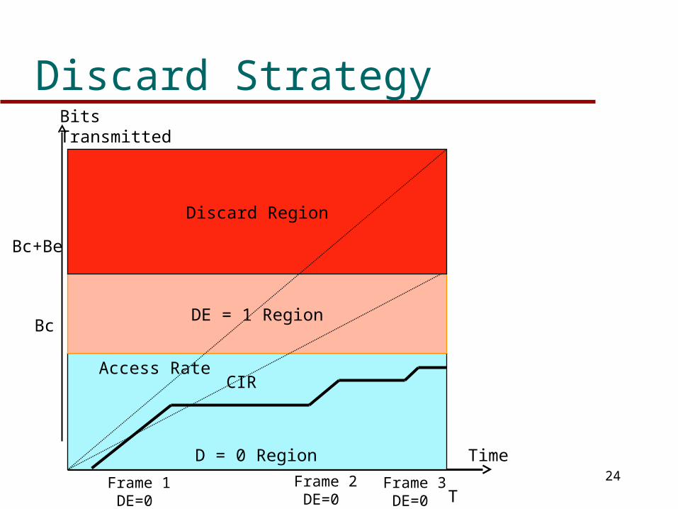
Discard Strategy
DE = 1 Region
Discard Region
Access RateCIR
D = 0 Region
BitsTransmitted
Bc
Bc+Be
Time
Frame 1 DE=0
Frame 2 DE=0
Frame 3 DE=0 T
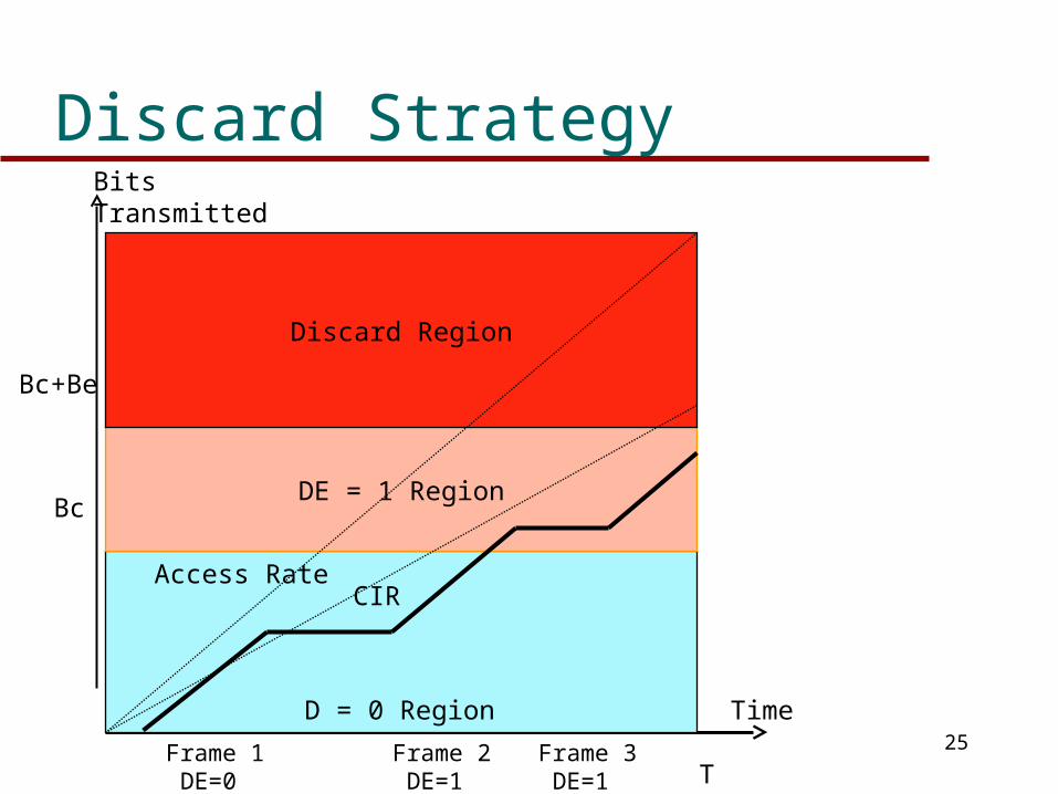
25
Discard Strategy
DE = 1 Region
Discard Region
Access RateCIR
D = 0 Region
BitsTransmitted
Bc
Bc+Be
Time
Frame 1 DE=0
Frame 2 DE=1
Frame 3 DE=1 T
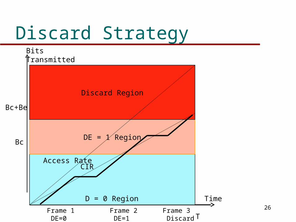
26
Discard Strategy
DE = 1 Region
Discard Region
Access RateCIR
D = 0 Region
BitsTransmitted
Bc
Bc+Be
Time
Frame 1 DE=0
Frame 2 DE=1
Frame 3 Discard T
27
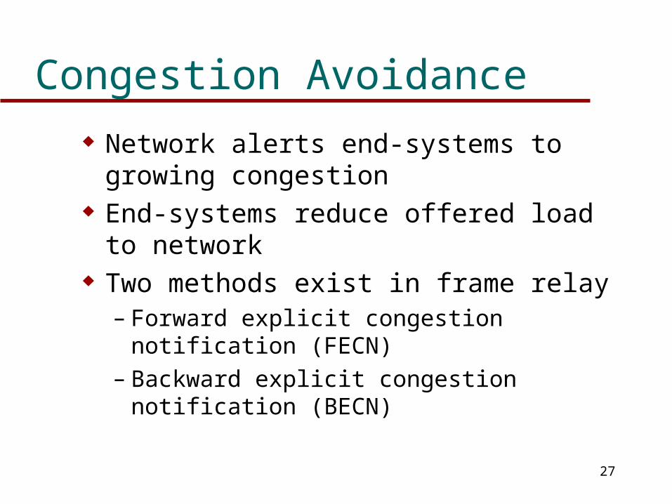
Congestion Avoidance
Network alerts end-systems to growing congestion
End-systems reduce offered load to network Two methods exist in frame relay
– Forward explicit congestion notification (FECN)– Backward explicit congestion notification (BECN)
28
Congestion Avoidance
Two bits, FECN and BECN exist in each frame address field
Any frame handler that detects may set either bit
Any frame handler receiving a frame with a bit set must forward the frame with the bit set
The bits therefore are signals to the end-user
29
Congestion Avoidance
The frame handler monitors outgoing queue lengths
Determines average queue length If average exceed a threshold, then FECN
bit or BECN bit or both is set They may be set for certain logical
connections or all depending on queue sizes
30
Congestion Avoidance
On receipt of BECN signal, user reduces rate of frame transmission
On receipt of FECN signal, user notifies peer user to reduce rate of frame transmission
31
Congestion Recovery
When higher-level end-end protocol detects frame loss it assumes congestion
This is called implicit signalling Flow control may be used to recover Gradual reduction of window size and
gradual increase as frame loss disappears