Embed Size (px)
Citation preview

1
Flow Control

2
TCP Flow Controlreceiver: explicitly
informs sender of (dynamically changing) amount of free buffer space RcvWindow field
in TCP segmentsender: keeps the
amount of transmitted, unACKed data less than most recently received RcvWindow
sender won’t overrun
receiver’s buffers bytransmitting too
much, too fast
flow control
receiver buffering
RcvBuffer = size or TCP Receive Buffer
RcvWindow = amount of spare room in Buffer

3 3
TCP Flow Control: How it Works
spare room in buffer= RcvWindow
source port # dest port #
applicationdata
(variable length)
sequence number
acknowledgement numberrcvr window size
ptr urgent datachecksum
FSRPAUheadlen
notused
Options (variable length)

4
TCP: setting timeouts

5
TCP Round Trip Time and TimeoutQ: how to set TCP
timeout value? longer than RTT
note: RTT will vary too short: premature
timeout unnecessary
retransmissions too long: slow
reaction to segment loss
Q: how to estimate RTT? SampleRTT: measured time
from segment transmission until ACK receipt ignore retransmissions,
cumulatively ACKed segments
SampleRTT will vary, want estimated RTT “smoother” use several recent
measurements, not just current SampleRTT

6
High-level Idea
Set timeout = average + safe margin

7
Estimating Round Trip Time
EstimatedRTT = (1- )*EstimatedRTT + *SampleRTT
Exponential weighted moving average influence of past sample decreases exponentially
fast typical value: = 0.125
SampleRTT: measured time from segment transmission until ACK receipt SampleRTT will vary, want a “smoother” estimated RTT
use several recent measurements, not just current SampleRTT
RTT: gaia.cs.umass.edu to fantasia.eurecom.fr
100
150
200
250
300
350
1 8 15 22 29 36 43 50 57 64 71 78 85 92 99 106
time (seconnds)
RTT
(mill
isec
onds
)
SampleRTT Estimated RTT

8
Setting TimeoutProblem: using the average of SampleRTT will generate
many timeouts due to network variations
Solution: EstimtedRTT plus “safety margin”
large variation in EstimatedRTT -> larger safety margin
TimeoutInterval = EstimatedRTT + 4*DevRTT
DevRTT = (1-)*DevRTT + *|SampleRTT-EstimatedRTT|
(typically, = 0.25)
Then set timeout interval:
RTT
freq.

9
An Example TCP Session

10
TCP Round Trip Time and TimeoutEstimatedRTT = (1-x)*EstimatedRTT + x*SampleRTT
Exponential weighted moving average influence of given sample decreases exponentially fast typical value of x: 0.1
Setting the timeout EstimtedRTT plus “safety margin” large variation in EstimatedRTT -> larger safety margin
Timeout = EstimatedRTT + 4*Deviation
Deviation = (1-x)*Deviation + x*|SampleRTT-EstimatedRTT|

11
Fast retransmit

12 12
Fast Retransmit
Timeout period often relatively long: long delay before
resending lost packet
Detect lost segments via duplicate ACKs sender often sends
many segments back-to-back
if segment is lost, there will likely be many duplicate ACKs
If sender receives 3 ACKs for the same data, it supposes that segment after ACKed data was lost: resend segment
before timer expires

13 13
Triple Duplicate Ack
1 2 3 4 5 6
2 3 4
Packets
Acknowledgements (waiting seq#)
4 4
7
4

14 14
event: ACK received, with ACK field value of y if (y > SendBase) { … SendBase = y if (there are currently not-yet-acknowledged segments) start timer … } else { increment count of dup ACKs received for y if (count of dup ACKs received for y = 3) { resend segment with sequence number y …
Fast Retransmit:
a duplicate ACK for already ACKed segment fast retransmit

15
Congestion Control

16
Principles of Congestion Control
Congestion: informally: “too many sources sending too
much data too fast for network to handle” manifestations:
lost packets (buffer overflow at routers) long delays (queuing in router buffers)
a highly important problem!

17
Causes/costs of congestion: scenario 1
two senders, two receivers one router, infinite buffers no retransmission

18
Causes/costs of congestion: scenario 1
Throughput increases with load Maximum total load C (Each session C/2) Large delays when congested
The load is stochastic

19
Causes/costs of congestion: scenario 2
one router, finite buffers sender retransmission of lost packet

20
Causes/costs of congestion: scenario 2 always: (goodput)
Like to maximize goodput!
“perfect” retransmission: retransmit only when loss:
Actual retransmission of delayed (not lost) packet
makes larger (than perfect case) for same
in
out
=
out
in
out
>
in

21
Causes/costs of congestion: scenario 2
“costs” of congestion: more work (retrans) for given “goodput” unneeded retransmissions: link carries (and
delivers) multiple copies of pkt
inin '
out
out
’in
out
’in

22
Causes/costs of congestion: scenario 3 four senders multihop paths timeout/retransmit
in
Q: what happens as and increase ?
in
23
Causes/costs of congestion: scenario 3
Another “cost” of congestion: when packet dropped, any “upstream” transmission capacity
used for that packet was wasted!

24
Approaches towards congestion control
End-end congestion control:
no explicit feedback from network
congestion inferred from end-system observed loss, delay
approach taken by TCP
Network-assisted congestion control:
routers provide feedback to end systems single bit indicating
congestion (SNA, DECbit, TCP/IP ECN, ATM)
explicit rate sender should send at
Two broad approaches towards congestion control:

25
Goals of congestion control
Throughput: Maximize goodput the total number of bits end-end
Fairness: Give different sessions “equal” share. Max-min fairness
• Maximize the minimum rate session. Single link:
• Capacity R• sessions m• Each sessions: R/m

26
Max-min fairness
Model: Graph G(V,e) and sessions s1 … sm
For each session si a rate ri is selected. The rates are a Max-Min fair allocation:
The allocation is maximal• No ri can be simply increased
Increasing allocation ri requires reducing• Some session j
• rj ≤ ri
Maximize minimum rate session.

27
Max-min fairness: Algorithm
Model: Graph G(V,e) and sessions s1 … sm
Algorithmic view: For each link compute its fair share f(e).
• Capacity / # session select minimal fair share link. Each session passing on it, allocate f(e). Subtract the capacities and delete sessions continue recessively.
Fluid view.

28
Max-min fairness
Example
Throughput versus fairness.

29
Case study: ATM ABR congestion control
ABR: available bit rate: “elastic service” if sender’s path “underloaded”:
sender can use available bandwidth if sender’s path congested:
sender lowers rate a minimum guaranteed rate
Aim: coordinate increase/decrease rate avoid loss!

30
Case study: ATM ABR congestion control
RM (resource management) cells: sent by sender, in between data cells
one out of every 32 cells.
RM cells returned to sender by receiver Each router modifies the RM cell Info in RM cell set by switches
“network-assisted” 2 bit info.
NI bit: no increase in rate (mild congestion) CI bit: congestion indication (lower rate)

31
Case study: ATM ABR congestion control
two-byte ER (explicit rate) field in RM cell congested switch may lower ER value in cell sender’ send rate thus minimum supportable rate on
path
EFCI bit in data cells: set to 1 in congested switch if data cell preceding RM cell has EFCI set, sender sets CI
bit in returned RM cell

32
Case study: ATM ABR congestion control How does the router selects its action:
selects a rate Set congestion bits Vendor dependent functionality
Advantages: fast response accurate response
Disadvantages: network level design Increase router tasks (load). Interoperability issues.

33
End to end control

34
End to end feedback
Abstraction: Alarm flag. observable at the end stations

35
Simple Abstraction

36
Simple Abstraction

37
Simple feedback model
Every RTT receive feedback High CongestionDecrease rate
Low congestionIncrease rate
Variable rate controls the sending rate.

38
Multiplicative Update
Congestion: Rate = Rate/2
No Congestion: Rate= Rate *2
Performance Fast response Un-fair:Ratios unchanged

39
Additive Update
Congestion: Rate = Rate -1
No Congestion: Rate= Rate +1
Performance Slow response
Fairness: Divides spare BW equally Difference remains unchanged
40
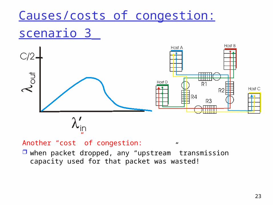
AIMD Scheme
Additive Increase Fairness: ratios improves
Multiplicative Decrease Fairness: ratio unchanged Fast response
Performance: Congestion -Fast response Fairness
overflow

41
AIMD: Two users, One link
BW limit
Fairness
Rate of User 1
Rat
e of
Use
r 2

42 42
TCP Congestion Control Closed-loop, end-to-end, window-based
congestion control Designed by Van Jacobson in late 1980s, based
on the AIMD alg. of Dah-Ming Chu and Raj Jain Works well so far: the bandwidth of the Internet
has increased by more than 200,000 times Many versions
TCP/Tahoe: this is a less optimized version TCP/Reno: many OSs today implement Reno
type congestion control TCP/Vegas: not currently used
For more details: see TCP/IP illustrated; or readhttp://lxr.linux.no/source/net/ipv4/tcp_input.c for linux implementation

43
TCP/Reno Congestion Detection
• 3 dup ACKs indicates network capable of delivering some segments
• timeout is “more alarming”
Philosophy:
Detect congestion in two cases and react differently:
3 dup ACKs timeout event

44
Basic Structure
Two “phases”slow-start: MIcongestion avoidance: AIMD
Important variables:cwnd: congestion window sizessthresh: threshold between the slow-
start phase and the congestion avoidance phase

45
Visualization of the Two Phases

46
Slow Start: MI
What is the goal? getting to equilibrium gradually but quickly
Implements the MI algorithm double cwnd every RTT until network
congested get a rough estimate of the optimal of cwnd

47
Slow-start
ACK for segment 1
segment 1cwnd = 1
cwnd = 2 segment 2segment 3
ACK for segments 2 + 3
cwnd = 4 segment 4segment 5segment 6segment 7
cwnd = 6
Initially:cwnd = 1;ssthresh = infinite (e.g., 64K);
For each newly ACKed segment:if (cwnd < ssthresh) /* slow start*/ cwnd = cwnd + 1;
cwnd = 8

48
Startup Behavior with Slow-start
See [Jac89]

49 49
TCP/Reno Congestion Avoidance Maintains equilibrium and reacts around
equilibrium
Implements the AIMD algorithm increases window by 1 per round-trip time
(how?) cuts window size
• to half when detecting congestion by 3DUP• to 1 if timeout• if already timeout, doubles timeout

50 50
TCP/Reno Congestion AvoidanceInitially:
cwnd = 1;ssthresh = infinite (e.g., 64K);
For each newly ACKed segment:if (cwnd < ssthresh) /* slow start*/ cwnd = cwnd + 1;else /* congestion avoidance; cwnd increases (approx.) by 1 per RTT */ cwnd += 1/cwnd;
Triple-duplicate ACKs: /* multiplicative decrease */
cwnd = ssthresh = cwnd/2;Timeout:
ssthresh = cwnd/2;cwnd = 1;
(if already timed out, double timeout value; this is called exponential backoff)

51 51
TCP/Reno: Big Picture
Time
cwnd
slowstart
congestionavoidance
TD
TD: Triple duplicate acknowledgementsTO: Timeout
TOssthresh
ssthresh ssthreshssthresh
congestionavoidance
TD
congestionavoidance
slow start
congestionavoidance
TD

52 52
A Session
Question: when cwnd is cut to half, why sending rate is not?

5353
TCP/Reno Queueing Dynamics
Consider congestion avoidance only
Time
cwnd
congestionavoidance
TD
ssthresh
bottleneckbandwidth
filling buffer
draining buffer
There is a filling and draining of buffer process for each TCP flow.

58
TCP Tahoe Congestion Avoidance
/* slowstart is over */ /* Congwin > threshold */Until (timeout) { /* loss event */ every ACK: Congwin += 1/Congwin }threshold = Congwin/2Congwin = 1perform slowstart
Congestion avoidance
TCP Taheo

59
TCP Reno Fast retransmit:
After receiving 3 duplicate ACK Resend first packet in window.
• Try to avoid waiting for timeout
Fast recovery: After retransmission do not enter slowstart. Threshold = Congwin/2 Congwin = 3 + Congwin/2 Each duplicate ACK received Congwin++ After new ACK
• Congwin = Threshold • return to congestion avoidance
Single packet drop: great!

60
TCP Congestion Window Trace
0
10
20
30
40
50
60
70
0 10 20 30 40 50 60
Time
Co
ng
esti
on
Win
do
w
threshold
congestionwindowtimeouts
slow start period
additive increase
fast retransmission

61
TCP Vegas:
Idea: track the RTT Try to avoid packet loss latency increases: lower rate latency very low: increase rate
Implementation: sample_RTT: current RTT Base_RTT: min. over sample_RTT Expected = Congwin / Base_RTT Actual = number of packets sent /
sample_RTT =Expected - Actual

62
TCP Vegas = Expected - Actual Congestion Avoidance:
two parameters: and , < If ( < ) Congwin = Congwin +1 If ( > ) Congwin = Congwin -1 Otherwise no change Note: Once per RTT
Slowstart parameter If ( > ) then move to congestion avoidance
Timeout: same as TCP Taheo

63
TCP Dynamics: Rate
TCP Reno with NO Fast Retransmit or Recovery Sending rate: Congwin*MSS / RTT Assume fixed RTT
W
W/2
Actual Sending rate: between W*MSS / RTT and (1/2) W*MSS / RTT Average (3/4) W*MSS / RTT

64
TCP Dynamics: Loss
Loss rate (TCP Reno) No Fast Retransmit or Recovery
Consider a cycle
Total packet sent: about (3/8) W2 MSS/RTT = O(W2) One packet loss
Loss Probability: p=O(1/W2) or W=O(1/p)
W
W/2

65
TCP latency modeling
Q: How long does it take to receive an object from a Web server after sending a request?
TCP connection establishment
data transfer delay
Notation, assumptions: Assume one link
between client and server of rate R
Assume: fixed congestion window, W segments
S: MSS (bits) O: object size (bits) no retransmissions
no loss, no corruption

66
TCP latency modeling
Optimal Setting: Time = O/R
Two cases to consider: WS/R > RTT + S/R:
ACK for first segment in window returns before window’s worth of data sent
WS/R < RTT + S/R: wait for ACK after sending window’s worth
of data sent

67
TCP latency Modeling
Case 1: latency = 2RTT + O/R Case 2: latency = 2RTT + O/R+ (K-1)[S/R + RTT - WS/R]
K:= O/WS

68
TCP Latency Modeling: Slow Start
Now suppose window grows according to slow start. Will show that the latency of one object of size O is:
R
S
R
SRTTP
R
ORTTLatency P )12(2
where P is the number of times TCP stalls at server:
}1,{min KQP
- where Q is the number of times the server would stall if the object were of infinite size.
- and K is the number of windows that cover the object.

69
TCP Latency Modeling: Slow Start (cont.)
RTT
initia te TCPconnection
requestobject
first w indow= S /R
second w indow= 2S /R
third w indow= 4S /R
fourth w indow= 8S /R
com pletetransm issionobject
delivered
tim e atc lient
tim e atserver
Example:
O/S = 15 segments
K = 4 windows
Q = 2
P = min{K-1,Q} = 2
Server stalls P=2 times.

70
TCP Latency Modeling: Slow Start (cont.)
R
S
R
SRTTPRTT
R
O
R
SRTT
R
SRTT
R
O
stallTimeRTTR
O
P
kP
k
P
pp
)12(][2
]2[2
2latency
1
1
1
window after the timestall 2 th1 kR
SRTT
R
S k
ementacknowledg receivesserver until
segment send tostartsserver whenfrom time RTTR
S
window k the transmit totime2 th1
R
Sk
RTT
initia te TCPconnection
requestobject
first w indow= S /R
second w indow= 2S /R
third w indow= 4S /R
fourth w indow= 8S /R
com pletetransm issionobject
delivered
tim e atc lient
tim e atserver