Embed Size (px)
Citation preview
1
ECE462/562
ISA and Datapath Review
Ali Akoglu
2
Instruction Set Architecture
• A very important abstraction
– interface between hardware and low-level software
– standardizes instructions, machine language bit patterns, etc.
– advantage: different implementations of the same architecture
• Modern instruction set architectures:
– IA-32, PowerPC, MIPS, SPARC, ARM, and others
3
MIPS arithmetic
• All instructions have 3 operands
• Operand order is fixed (destination first)
Example:
C code: a = b + c
MIPS ‘code’: add a, b, c
4
MIPS arithmetic
• Design Principle: simplicity favors regularity.
• Of course this complicates some things...
C code: a = b + c + d;
MIPS code: add a, b, cadd a, a, d
• Operands must be registers, only 32 registers provided
• Each register contains 32 bits
5
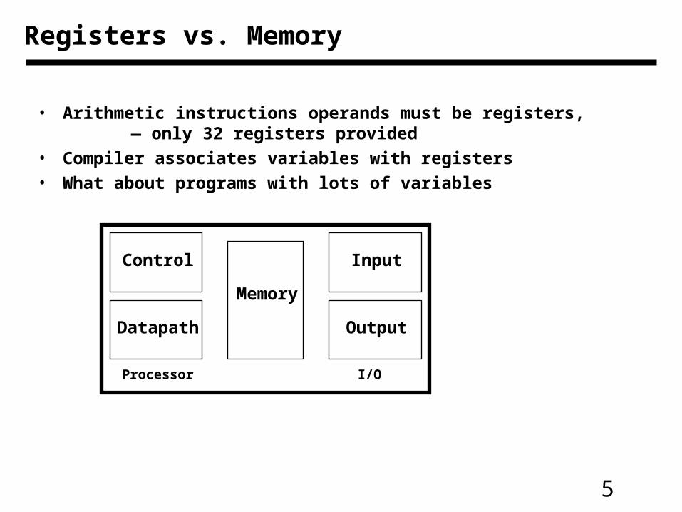
Registers vs. Memory
Processor I/O
Control
Datapath
Memory
Input
Output
• Arithmetic instructions operands must be registers, — only 32 registers provided
• Compiler associates variables with registers
• What about programs with lots of variables
6
Memory Organization
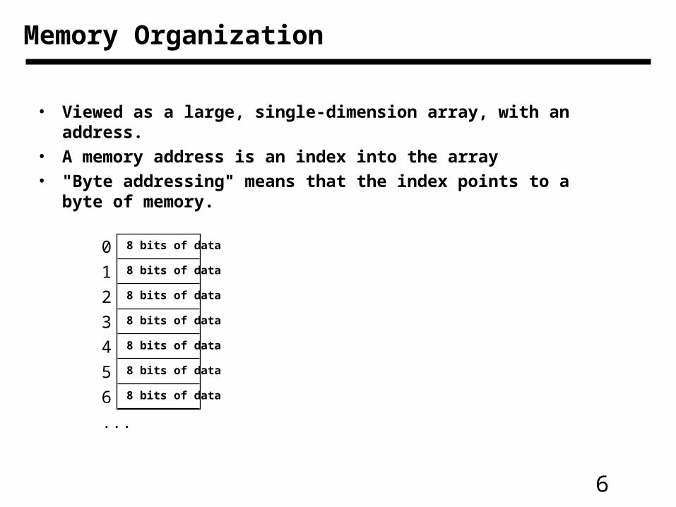
• Viewed as a large, single-dimension array, with an address.
• A memory address is an index into the array
• "Byte addressing" means that the index points to a byte of memory.
0
1
2
3
4
5
6
...
8 bits of data
8 bits of data
8 bits of data
8 bits of data
8 bits of data
8 bits of data
8 bits of data
7
Memory Organization
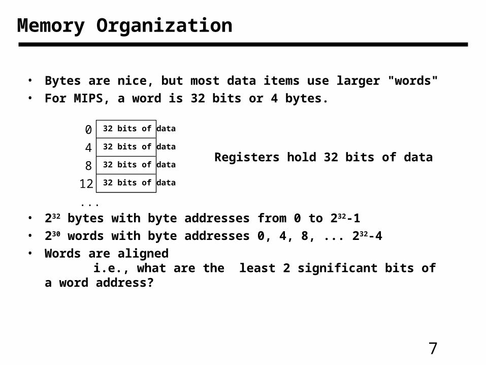
• Bytes are nice, but most data items use larger "words"
• For MIPS, a word is 32 bits or 4 bytes.
• 232 bytes with byte addresses from 0 to 232-1
• 230 words with byte addresses 0, 4, 8, ... 232-4
• Words are alignedi.e., what are the least 2 significant bits of a word address?
0
4
8
12
...
32 bits of data
32 bits of data
32 bits of data
32 bits of data
Registers hold 32 bits of data
8
So far we’ve learned:
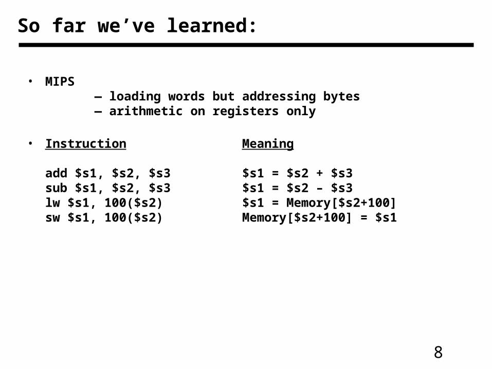
• MIPS— loading words but addressing bytes— arithmetic on registers only
• Instruction Meaning
add $s1, $s2, $s3 $s1 = $s2 + $s3sub $s1, $s2, $s3 $s1 = $s2 – $s3lw $s1, 100($s2) $s1 = Memory[$s2+100] sw $s1, 100($s2) Memory[$s2+100] = $s1
9
Instructions
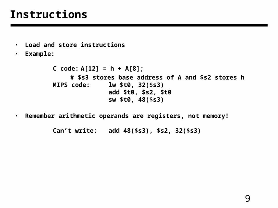
• Load and store instructions• Example:
C code: A[12] = h + A[8];
# $s3 stores base address of A and $s2 stores hMIPS code: lw $t0, 32($s3)
add $t0, $s2, $t0sw $t0, 48($s3)
• Remember arithmetic operands are registers, not memory!
Can’t write: add 48($s3), $s2, 32($s3)
10
Summary
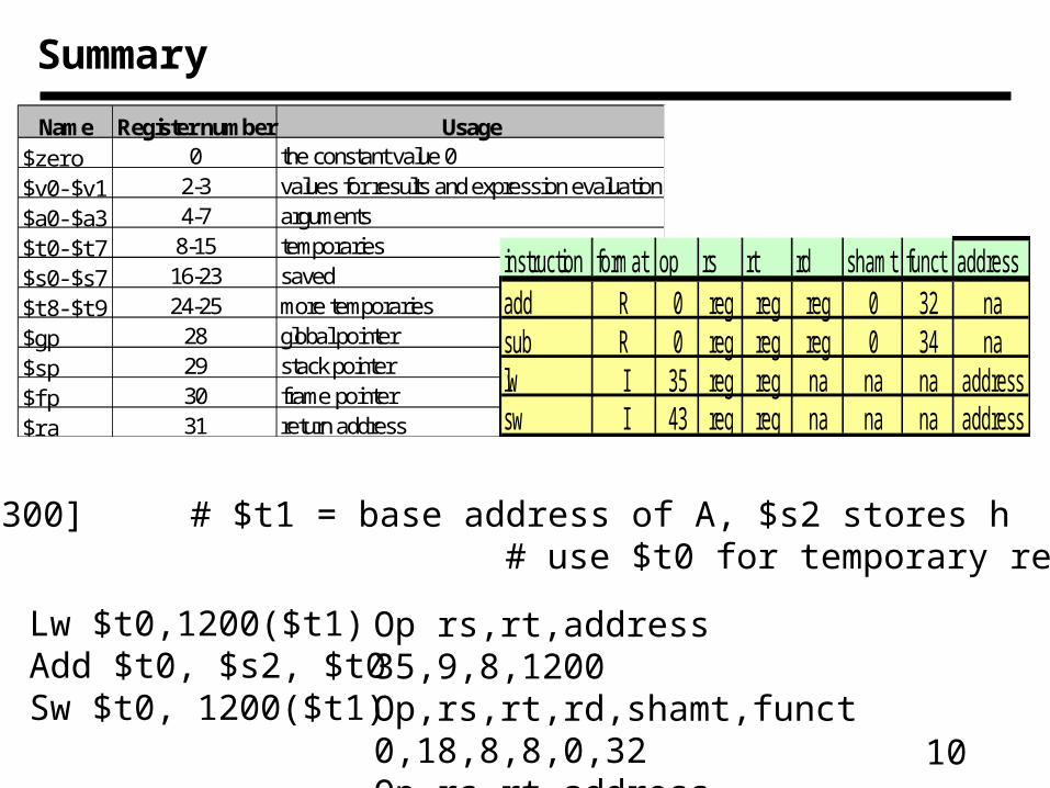
Name Register number Usage$zero 0 the constant value 0$v0-$v1 2-3 values for results and expression evaluation$a0-$a3 4-7 arguments$t0-$t7 8-15 temporaries$s0-$s7 16-23 saved$t8-$t9 24-25 more temporaries$gp 28 global pointer$sp 29 stack pointer$fp 30 frame pointer$ra 31 return address
A[300]=h+A[300] # $t1 = base address of A, $s2 stores h # use $t0 for temporary register
Lw $t0,1200($t1)Add $t0, $s2, $t0Sw $t0, 1200($t1)
instruction format op rs rt rd shamt funct addressadd R 0 reg reg reg 0 32 nasub R 0 reg reg reg 0 34 nalw I 35 reg reg na na na addresssw I 43 reg reg na na na address
Op rs,rt,address 35,9,8,1200Op,rs,rt,rd,shamt,funct 0,18,8,8,0,32Op,rs,rt,address 43,9,8,1200
11
Policy of Use Conventions
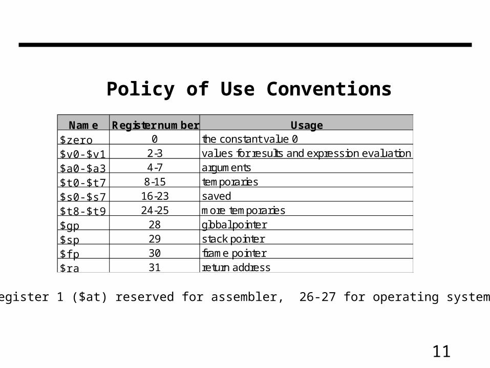
Name Register number Usage$zero 0 the constant value 0$v0-$v1 2-3 values for results and expression evaluation$a0-$a3 4-7 arguments$t0-$t7 8-15 temporaries$s0-$s7 16-23 saved$t8-$t9 24-25 more temporaries$gp 28 global pointer$sp 29 stack pointer$fp 30 frame pointer$ra 31 return address
Register 1 ($at) reserved for assembler, 26-27 for operating system
12
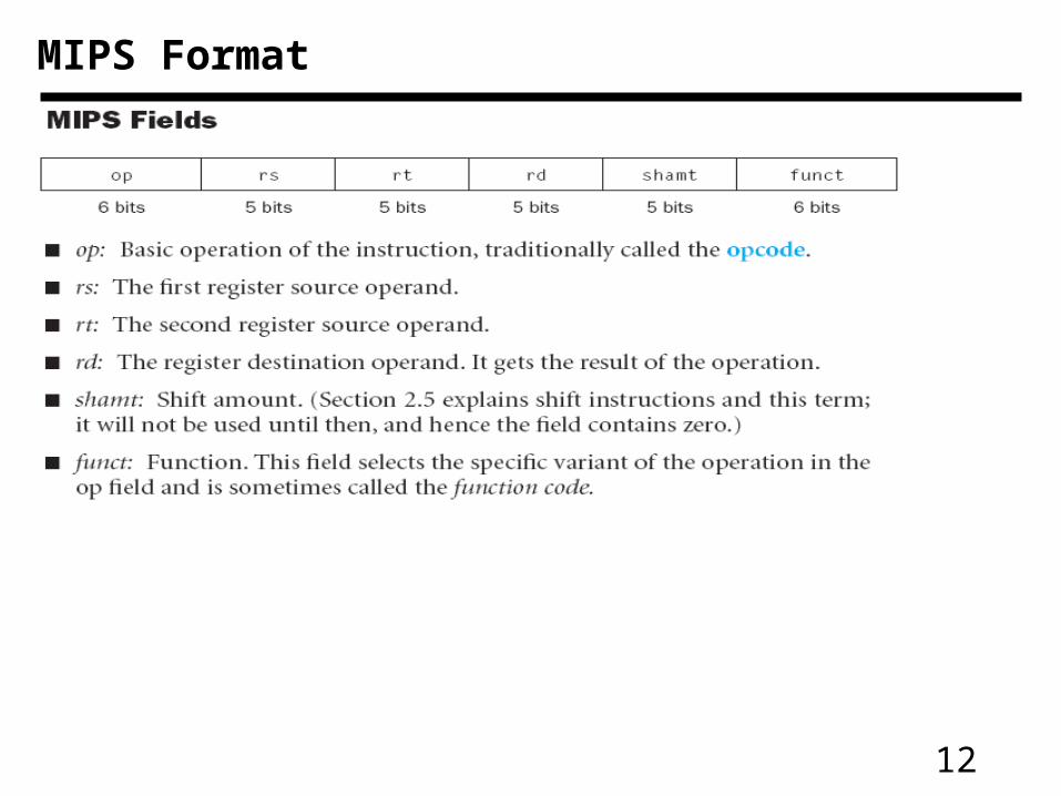
MIPS Format
13
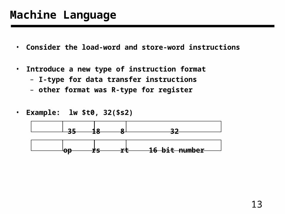
• Consider the load-word and store-word instructions
• Introduce a new type of instruction format
– I-type for data transfer instructions
– other format was R-type for register
• Example: lw $t0, 32($s2)
35 18 8 32
op rs rt 16 bit number
Machine Language
14
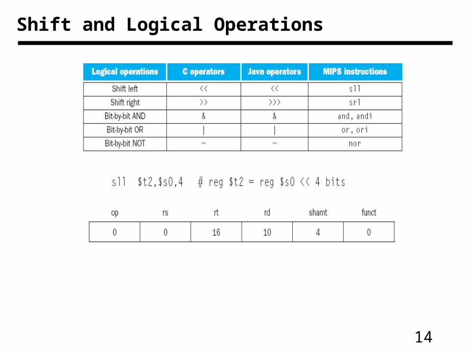
Shift and Logical Operations
15
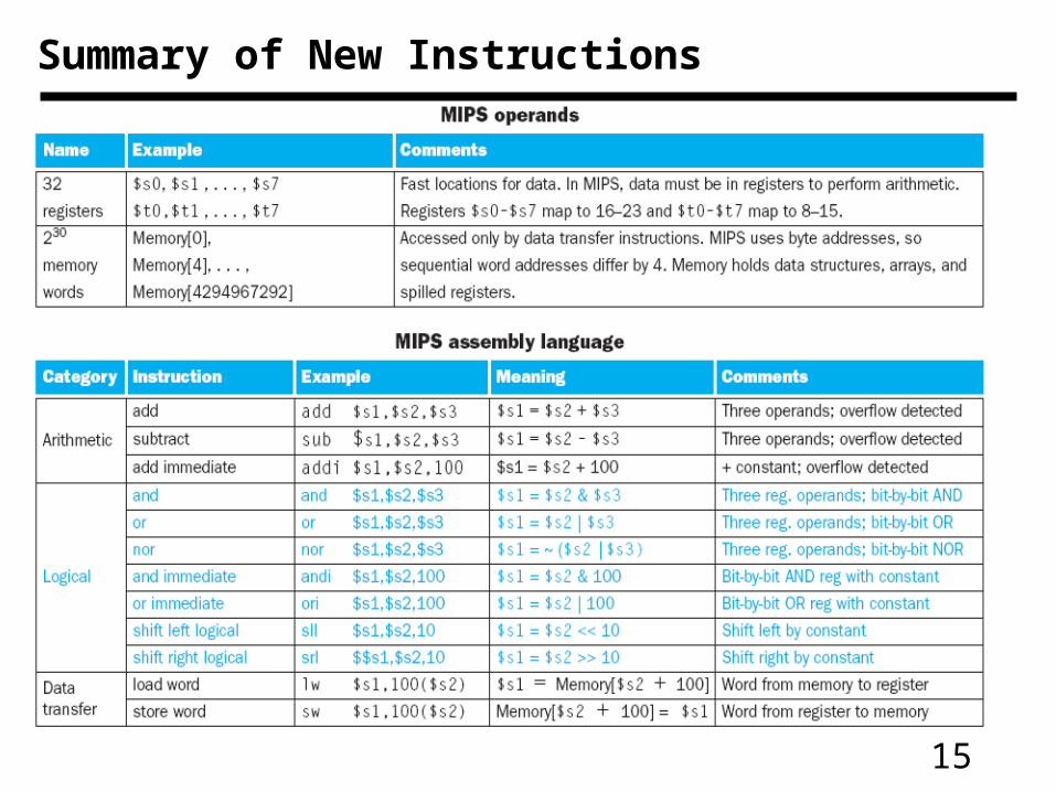
Summary of New Instructions
16
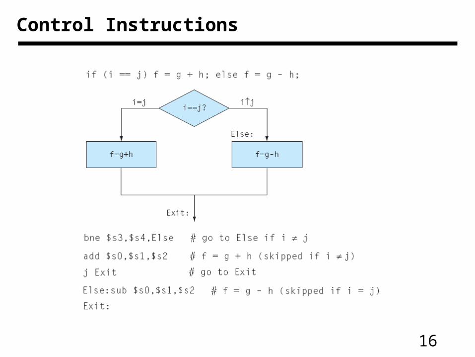
Control Instructions
17
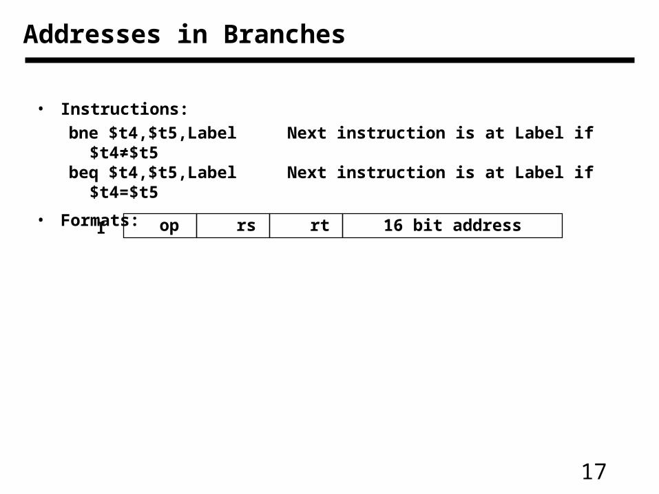
• Instructions:
bne $t4,$t5,Label Next instruction is at Label if $t4≠$t5beq $t4,$t5,Label Next instruction is at Label if $t4=$t5
• Formats:
op rs rt 16 bit addressI
Addresses in Branches
18
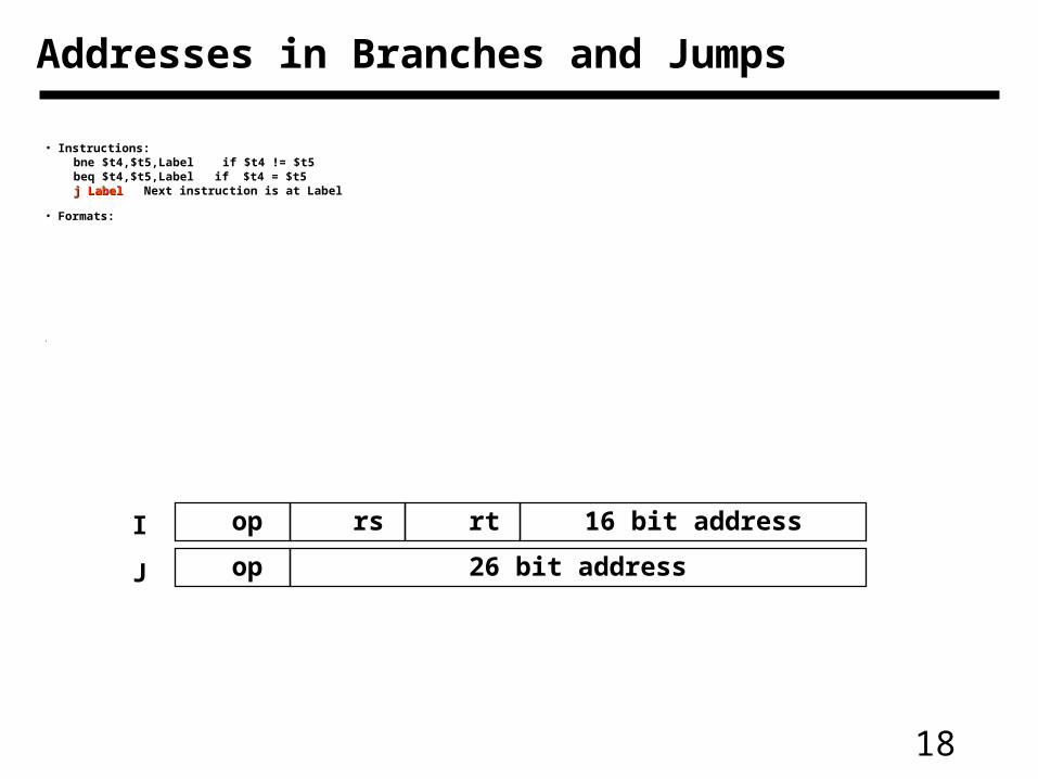
• Instructions:bne $t4,$t5,Label if $t4 != $t5beq $t4,$t5,Label if $t4 = $t5j Labelj Label Next instruction is at Label
• Formats:
•
op rs rt 16 bit address
op 26 bit address
I
J
Addresses in Branches and Jumps
19
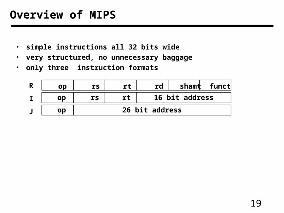
• simple instructions all 32 bits wide
• very structured, no unnecessary baggage
• only three instruction formats
op rs rt rd shamt funct
op rs rt 16 bit address
op 26 bit address
R
I
J
Overview of MIPS
20
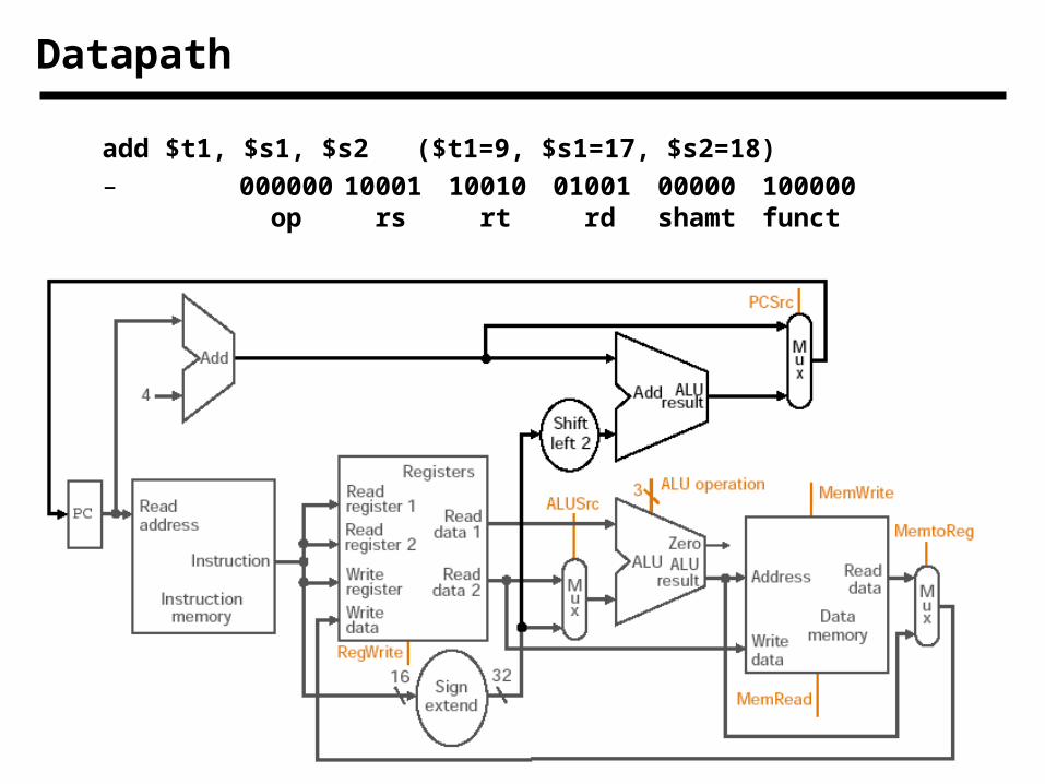
Datapath
add $t1, $s1, $s2 ($t1=9, $s1=17, $s2=18)
– 000000 10001 10010 01001 00000 100000 op rs rt rd shamt funct
21
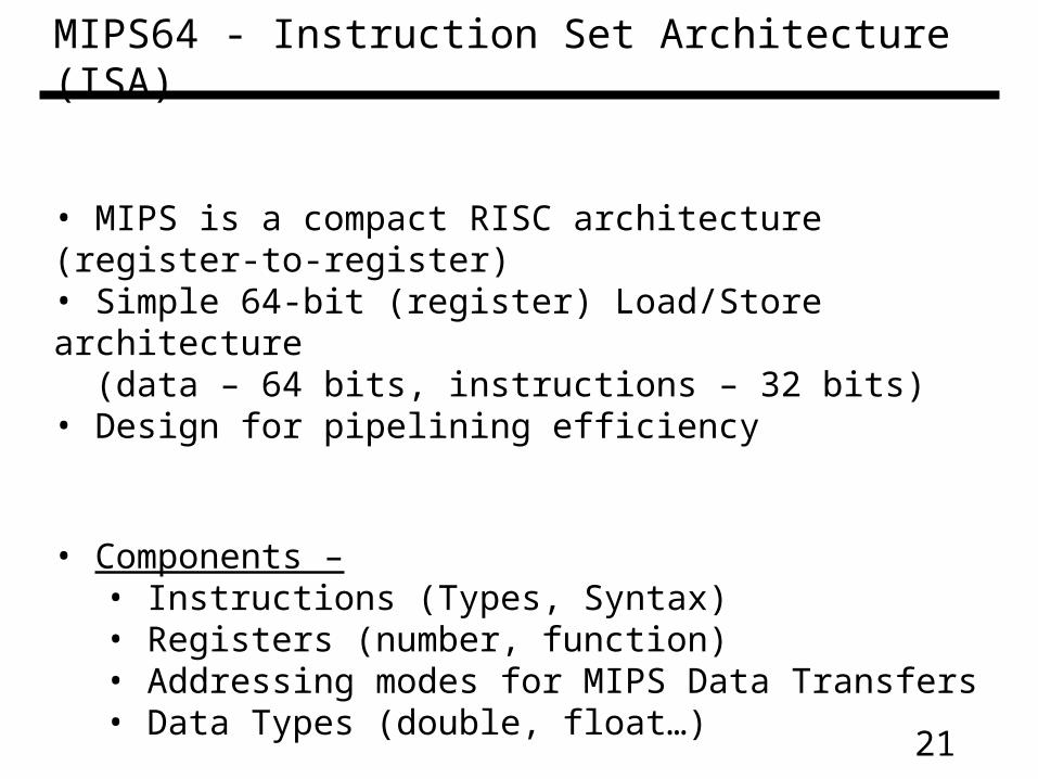
MIPS64 - Instruction Set Architecture (ISA)
• MIPS is a compact RISC architecture (register-to-register) • Simple 64-bit (register) Load/Store architecture (data – 64 bits, instructions – 32 bits)• Design for pipelining efficiency
• Components – • Instructions (Types, Syntax)• Registers (number, function)• Addressing modes for MIPS Data Transfers• Data Types (double, float…)
22
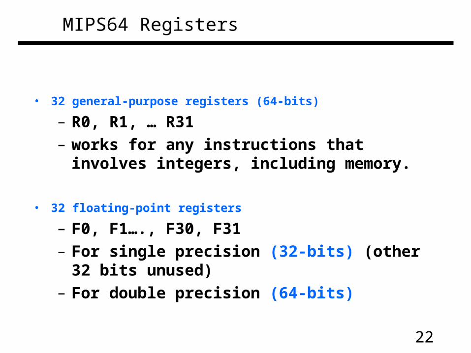
MIPS64 Registers
• 32 general-purpose registers (64-bits)
– R0, R1, … R31– works for any instructions that involves integers,
including memory.
• 32 floating-point registers
– F0, F1…., F30, F31– For single precision (32-bits) (other 32 bits
unused)– For double precision (64-bits)
23
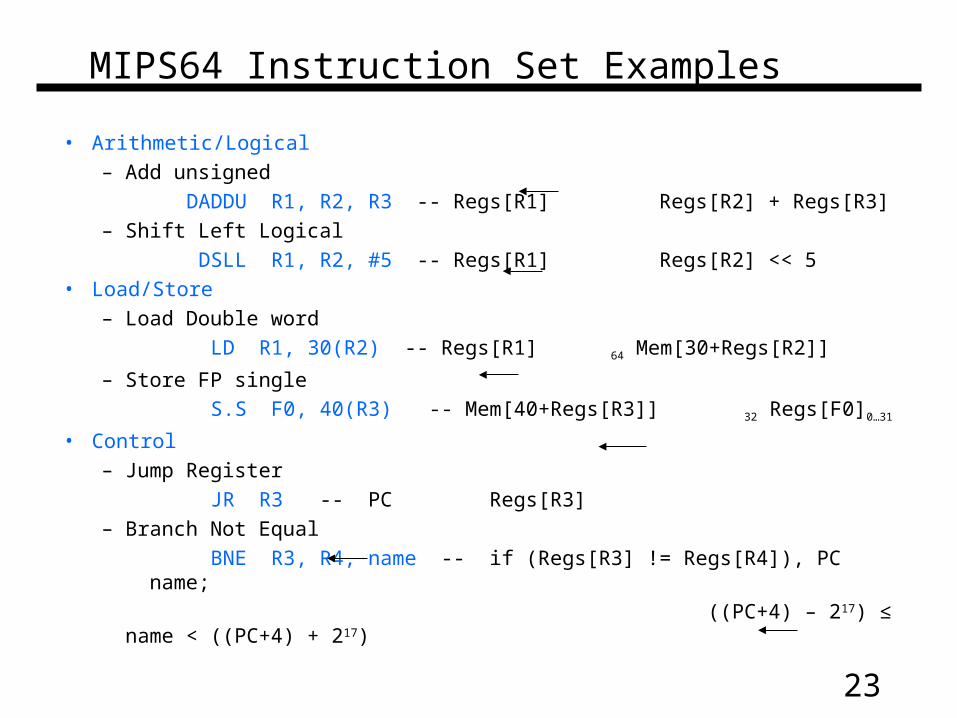
MIPS64 Instruction Set Examples
• Arithmetic/Logical– Add unsigned
DADDU R1, R2, R3 -- Regs[R1] Regs[R2] + Regs[R3]– Shift Left Logical
DSLL R1, R2, #5 -- Regs[R1] Regs[R2] << 5• Load/Store
– Load Double word
LD R1, 30(R2) -- Regs[R1] 64 Mem[30+Regs[R2]]
– Store FP single
S.S F0, 40(R3) -- Mem[40+Regs[R3]] 32 Regs[F0]0…31
• Control– Jump Register
JR R3 -- PC Regs[R3]– Branch Not Equal
BNE R3, R4, name -- if (Regs[R3] != Regs[R4]), PC name;
((PC+4) – 217) ≤ name < ((PC+4) + 217)
24
MIPS64 Instruction Set Architecture
• For more, please refer to –
– Appendix A of the book (5th Edition)
25
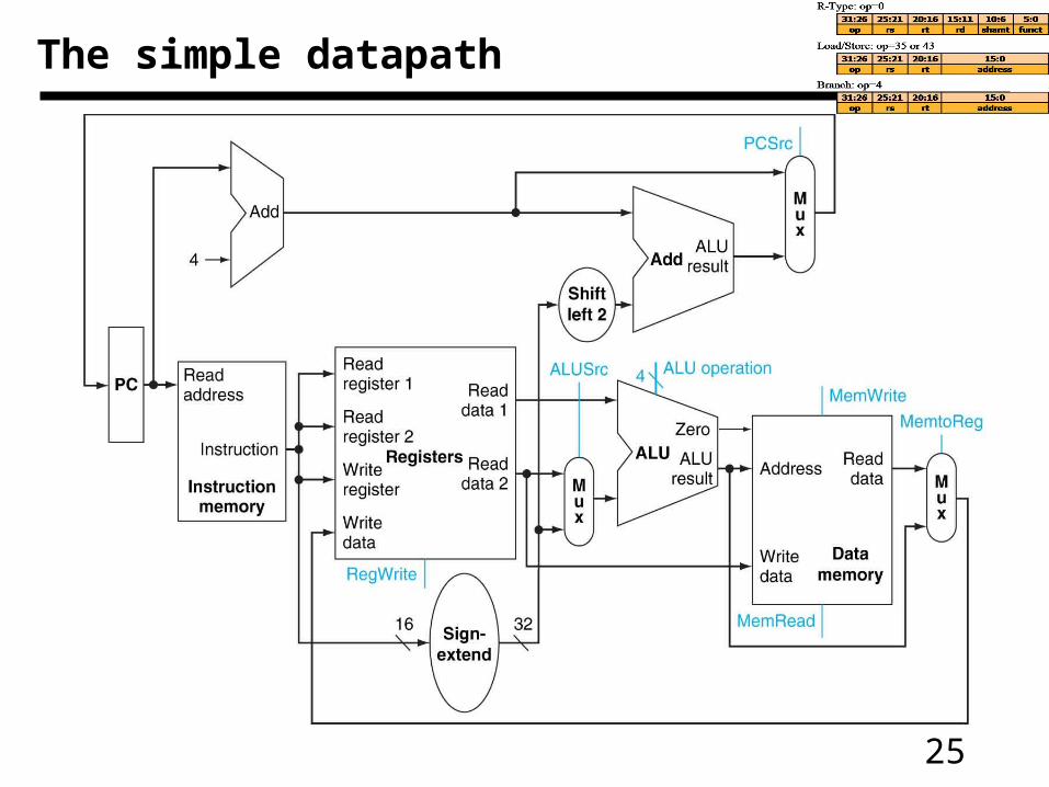
The simple datapath
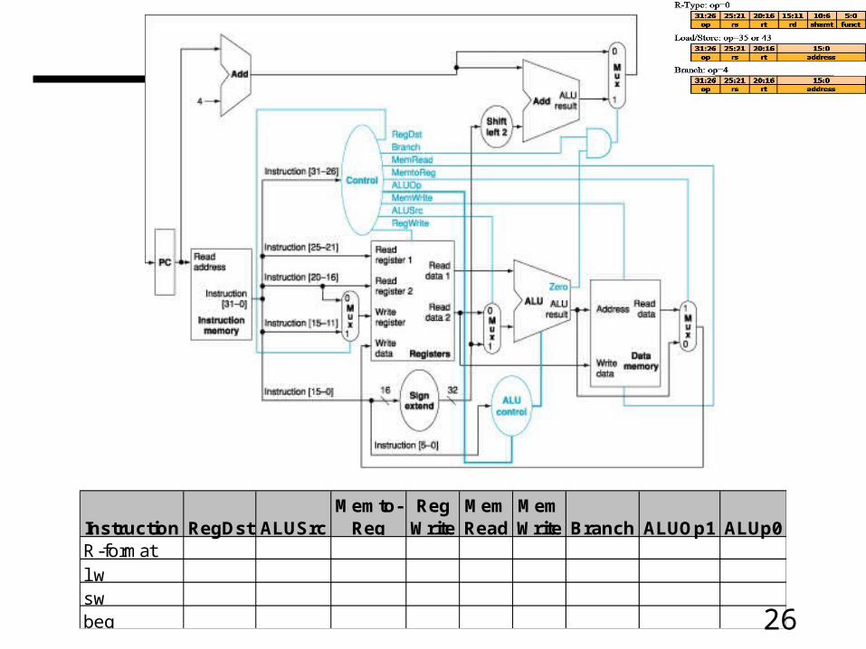
26
Instruction RegDst ALUSrcMemto-
RegReg
WriteMem Read
Mem Write Branch ALUOp1 ALUp0
R-formatlwswbeq
27
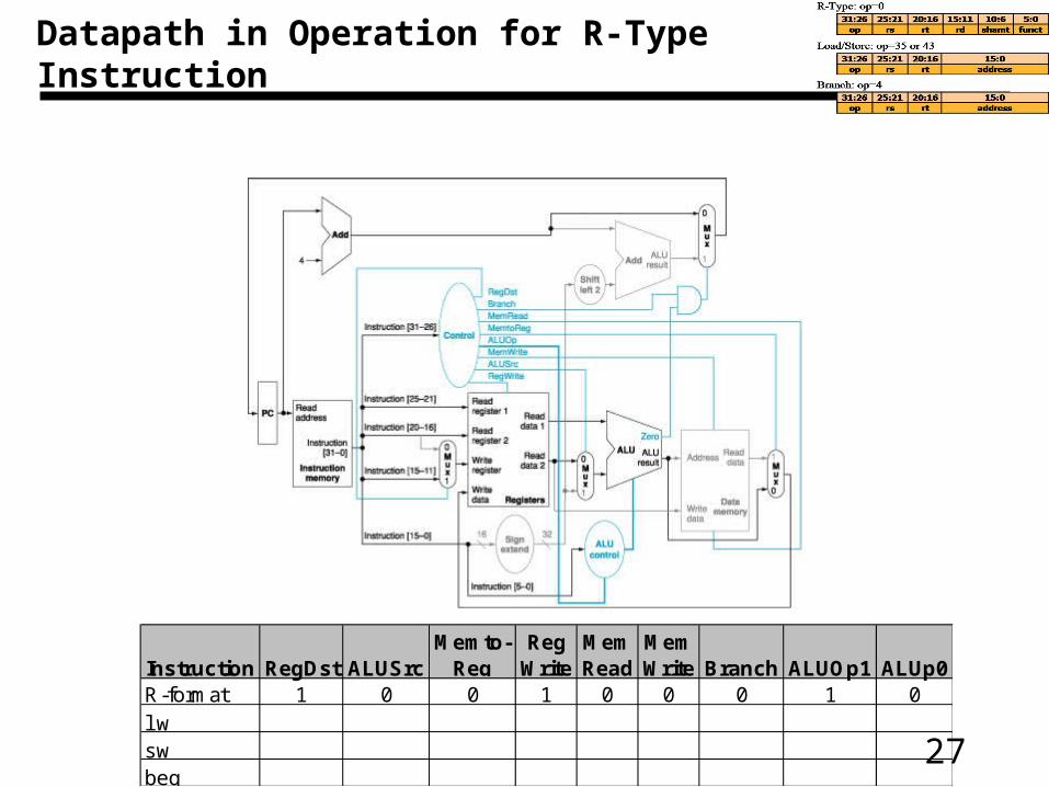
Datapath in Operation for R-Type Instruction
Instruction RegDst ALUSrcMemto-
RegReg
WriteMem Read
Mem Write Branch ALUOp1 ALUp0
R-format 1 0 0 1 0 0 0 1 0lwswbeq
28
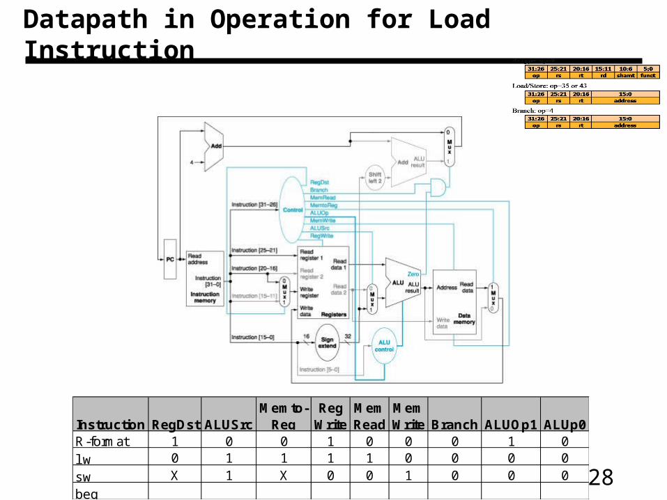
Datapath in Operation for Load Instruction
Instruction RegDst ALUSrcMemto-
RegReg
WriteMem Read
Mem Write Branch ALUOp1 ALUp0
R-format 1 0 0 1 0 0 0 1 0lw 0 1 1 1 1 0 0 0 0sw X 1 X 0 0 1 0 0 0beq
29
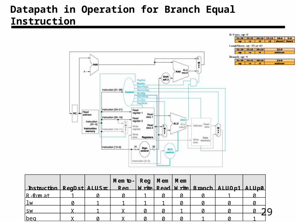
Datapath in Operation for Branch Equal Instruction
Instruction RegDst ALUSrcMemto-
RegReg
WriteMem Read
Mem Write Branch ALUOp1 ALUp0
R-format 1 0 0 1 0 0 0 1 0lw 0 1 1 1 1 0 0 0 0sw X 1 X 0 0 1 0 0 0beq X 0 X 0 0 0 1 0 1
30
Single Cycle Problems
– Wasteful of area
• Each unit used once per clock cycle
– Clock cycle equal to worst case scenario
• Will reducing the delay of common case help?
31
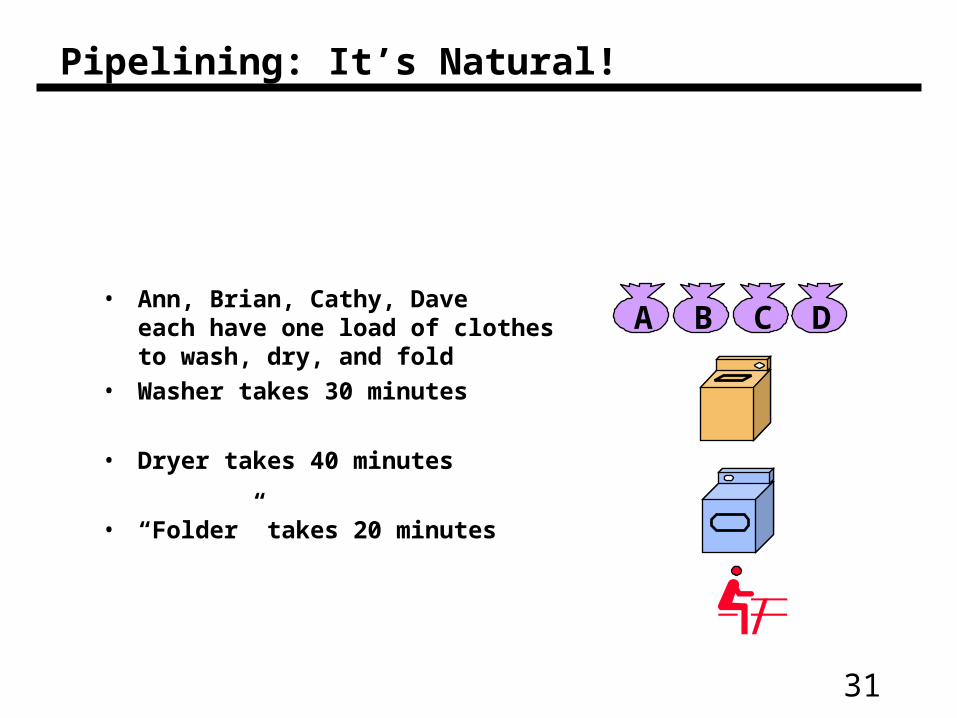
Pipelining: It’s Natural!
• Ann, Brian, Cathy, Dave each have one load of clothes to wash, dry, and fold
• Washer takes 30 minutes
• Dryer takes 40 minutes
• “Folder” takes 20 minutes
A B C D
32
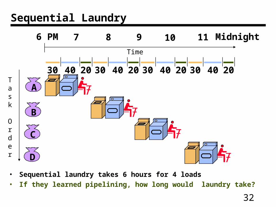
Sequential Laundry
• Sequential laundry takes 6 hours for 4 loads
• If they learned pipelining, how long would laundry take?
A
B
C
D
30 40 20 30 40 20 30 40 20 30 40 20
6 PM 7 8 9 10 11 Midnight
Task
Order
Time
33
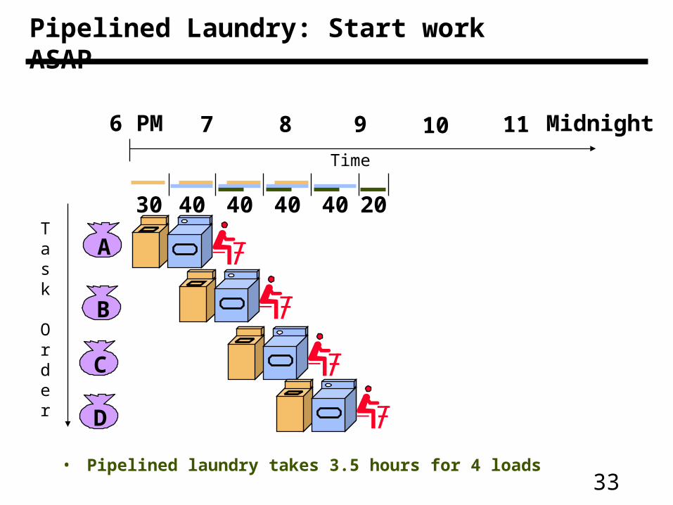
Pipelined Laundry: Start work ASAP
• Pipelined laundry takes 3.5 hours for 4 loads
A
B
C
D
6 PM 7 8 9 10 11 Midnight
Task
Order
Time
30 40 40 40 40 20
34
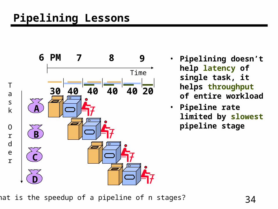
Pipelining Lessons
• Pipelining doesn’t help latency of single task, it helps throughput of entire workload
• Pipeline rate limited by slowest pipeline stageA
B
C
D
6 PM 7 8 9
Task
Order
Time
30 40 40 40 40 20
What is the speedup of a pipeline of n stages?
35
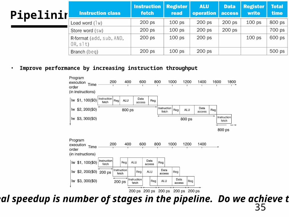
Pipelining
• Improve performance by increasing instruction throughput
Ideal speedup is number of stages in the pipeline. Do we achieve this?
36
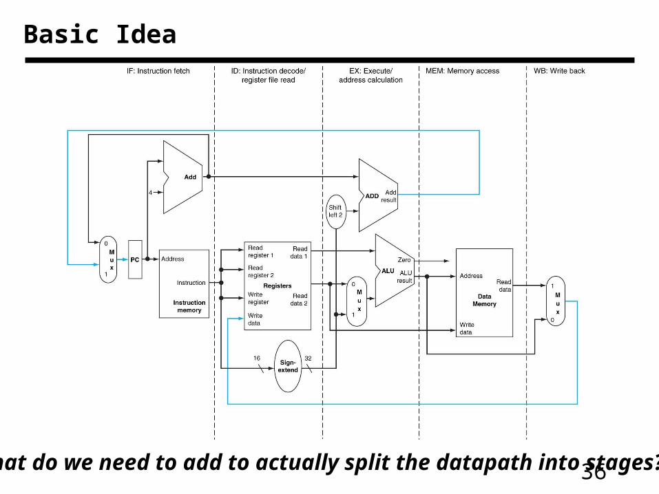
Basic Idea
What do we need to add to actually split the datapath into stages?
37
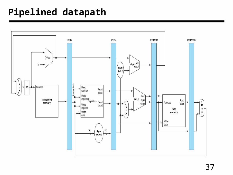
Pipelined datapath
38
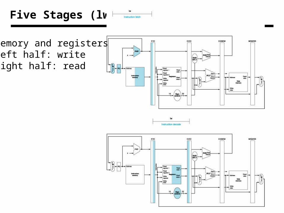
Five Stages (lw)
Memory and registersLeft half: writeRight half: read
39
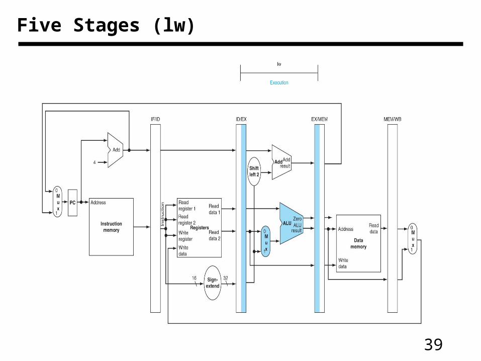
Five Stages (lw)
40
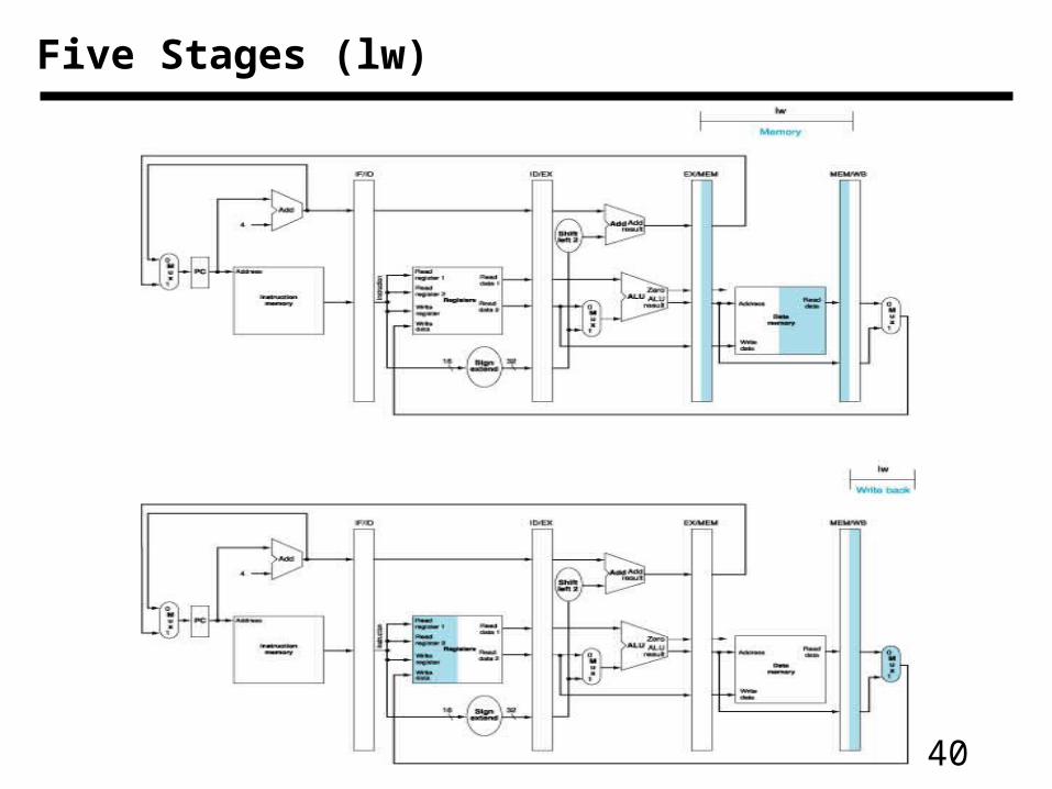
Five Stages (lw)
41
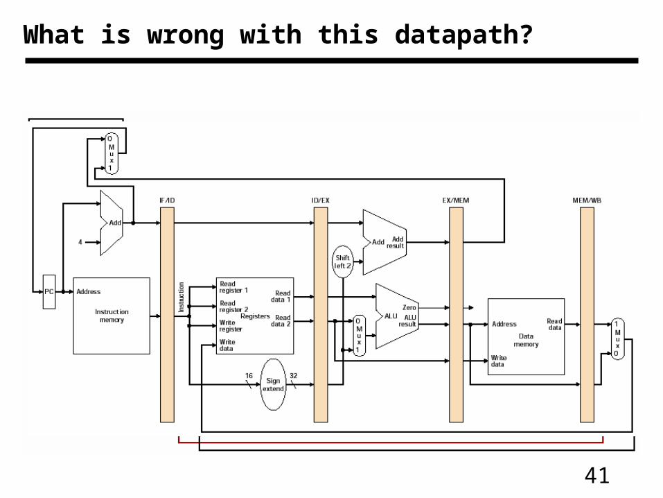
What is wrong with this datapath?
42
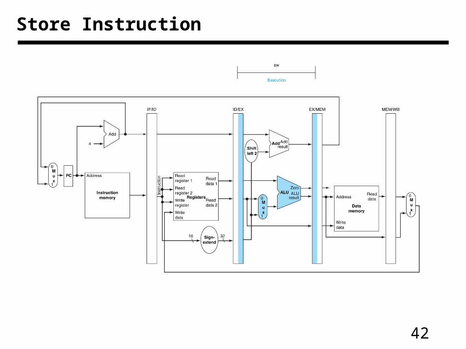
Store Instruction
43
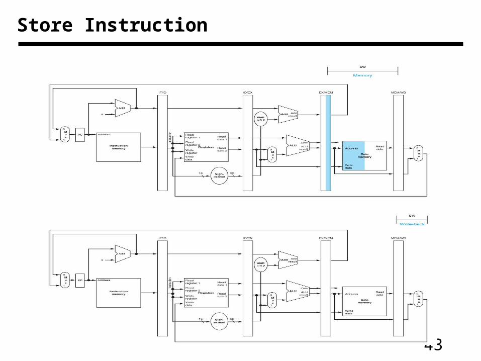
Store Instruction
44
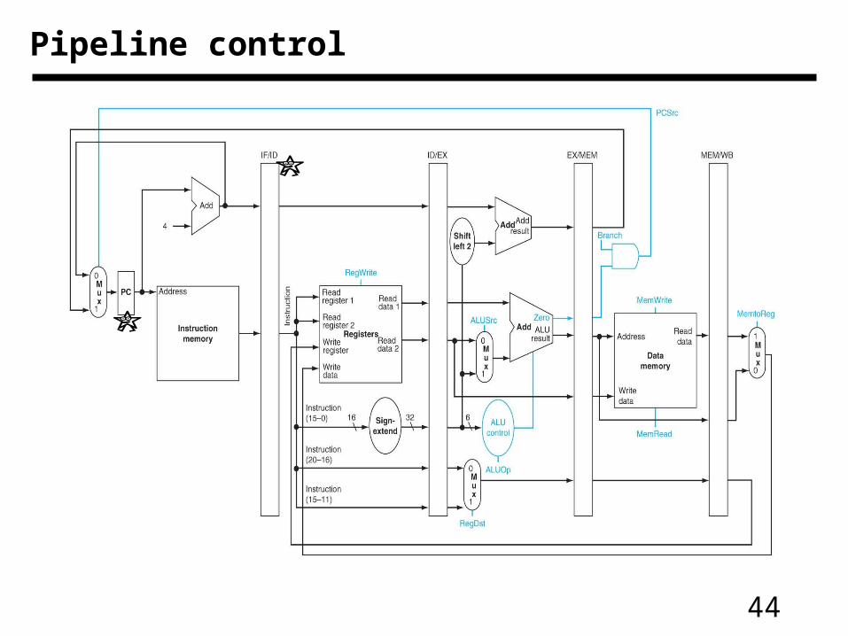
Pipeline control
45
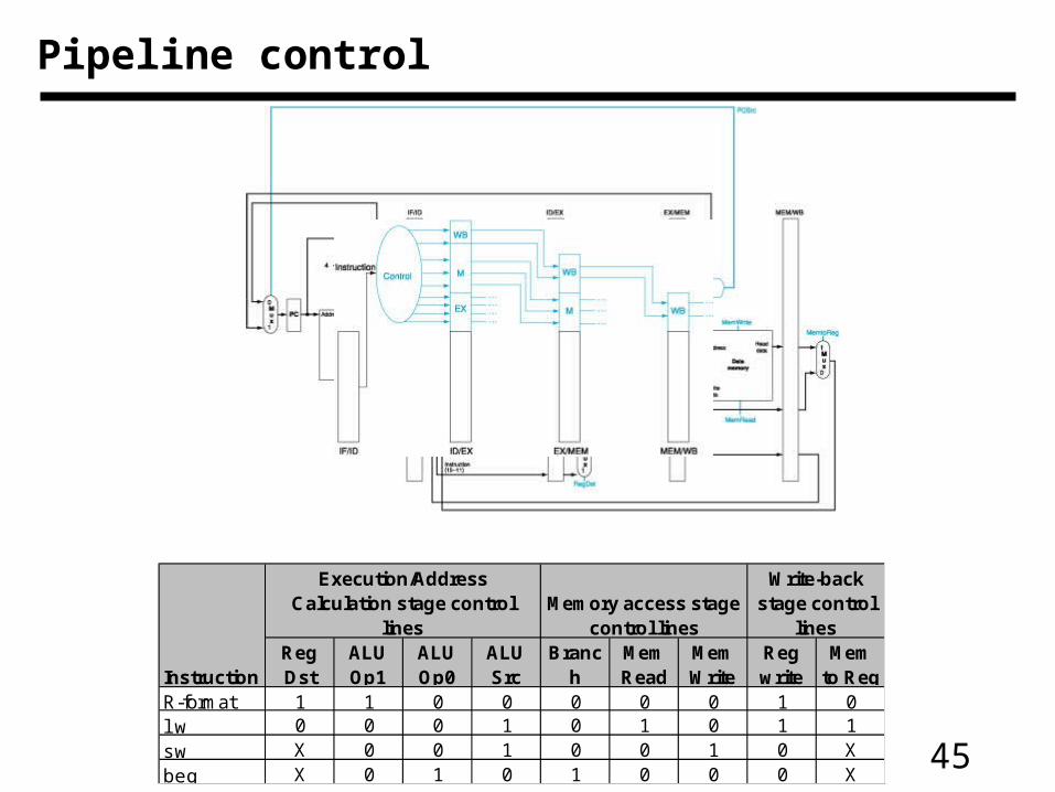
Execution/Address Calculation stage control
linesMemory access stage
control lines
Write-back stage control
lines
InstructionReg Dst
ALU Op1
ALU Op0
ALU Src
Branch
Mem Read
Mem Write
Reg write
Mem to Reg
R-format 1 1 0 0 0 0 0 1 0lw 0 0 0 1 0 1 0 1 1sw X 0 0 1 0 0 1 0 Xbeq X 0 1 0 1 0 0 0 X
Pipeline control
46
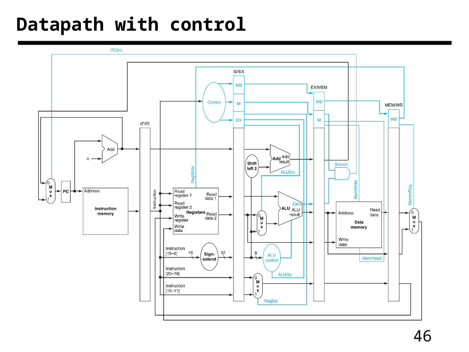
Datapath with control
47
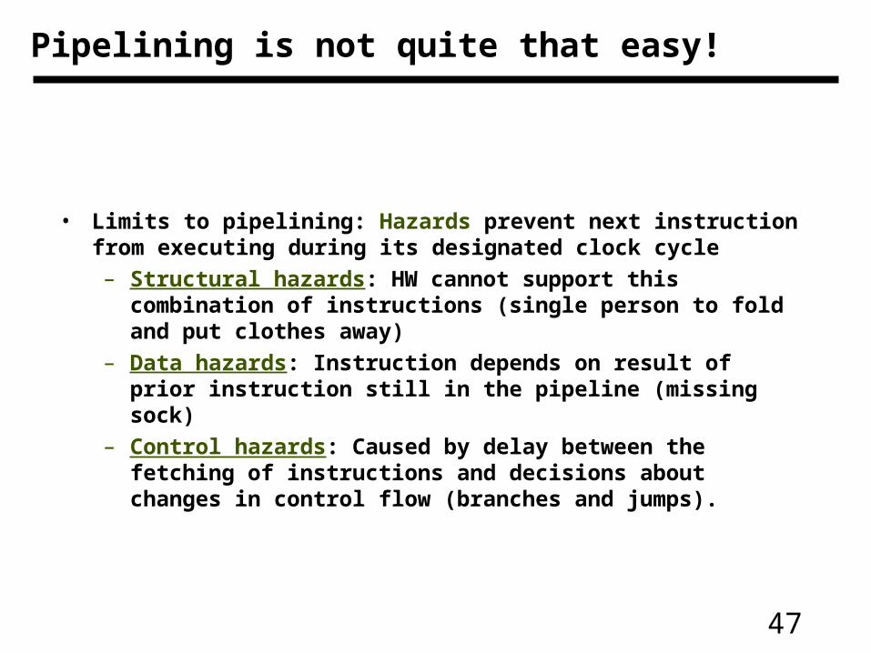
Pipelining is not quite that easy!
• Limits to pipelining: Hazards prevent next instruction from executing during its designated clock cycle
– Structural hazards: HW cannot support this combination of instructions (single person to fold and put clothes away)
– Data hazards: Instruction depends on result of prior instruction still in the pipeline (missing sock)
– Control hazards: Caused by delay between the fetching of instructions and decisions about changes in control flow (branches and jumps).
48
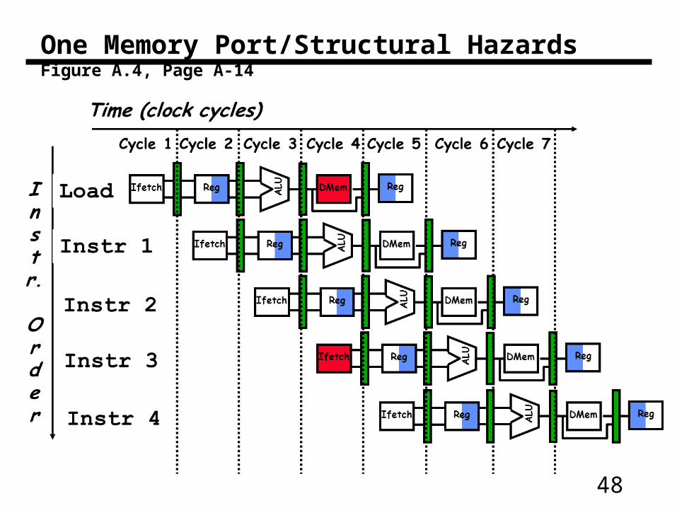
One Memory Port/Structural HazardsFigure A.4, Page A-14
49
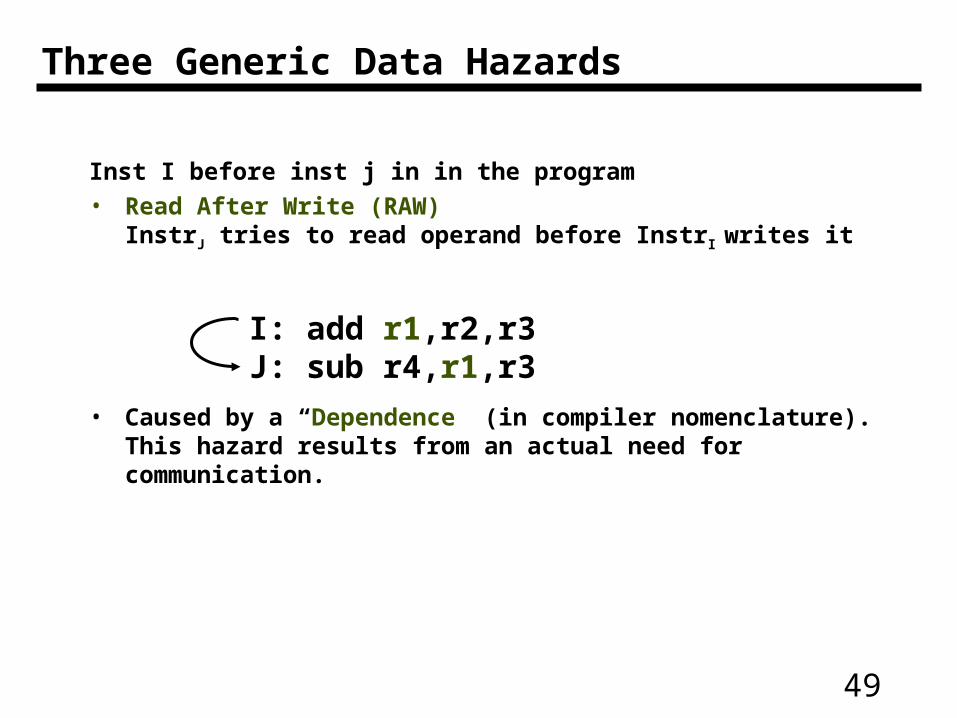
Inst I before inst j in in the program
• Read After Write (RAW) InstrJ tries to read operand before InstrI writes it
• Caused by a “Dependence” (in compiler nomenclature). This hazard results from an actual need for communication.
Three Generic Data Hazards
I: add r1,r2,r3J: sub r4,r1,r3
50
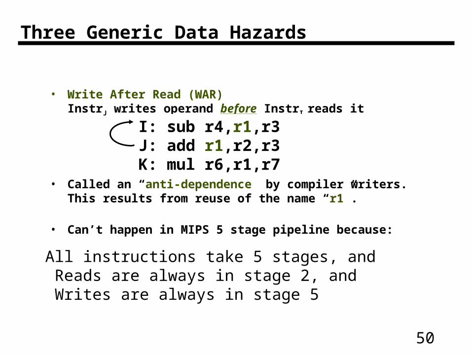
• Write After Read (WAR) InstrJ writes operand before InstrI reads it
• Called an “anti-dependence” by compiler writers.This results from reuse of the name “r1”.
• Can’t happen in MIPS 5 stage pipeline because:
I: sub r4,r1,r3 J: add r1,r2,r3K: mul r6,r1,r7
Three Generic Data Hazards
All instructions take 5 stages, and Reads are always in stage 2, and Writes are always in stage 5
51
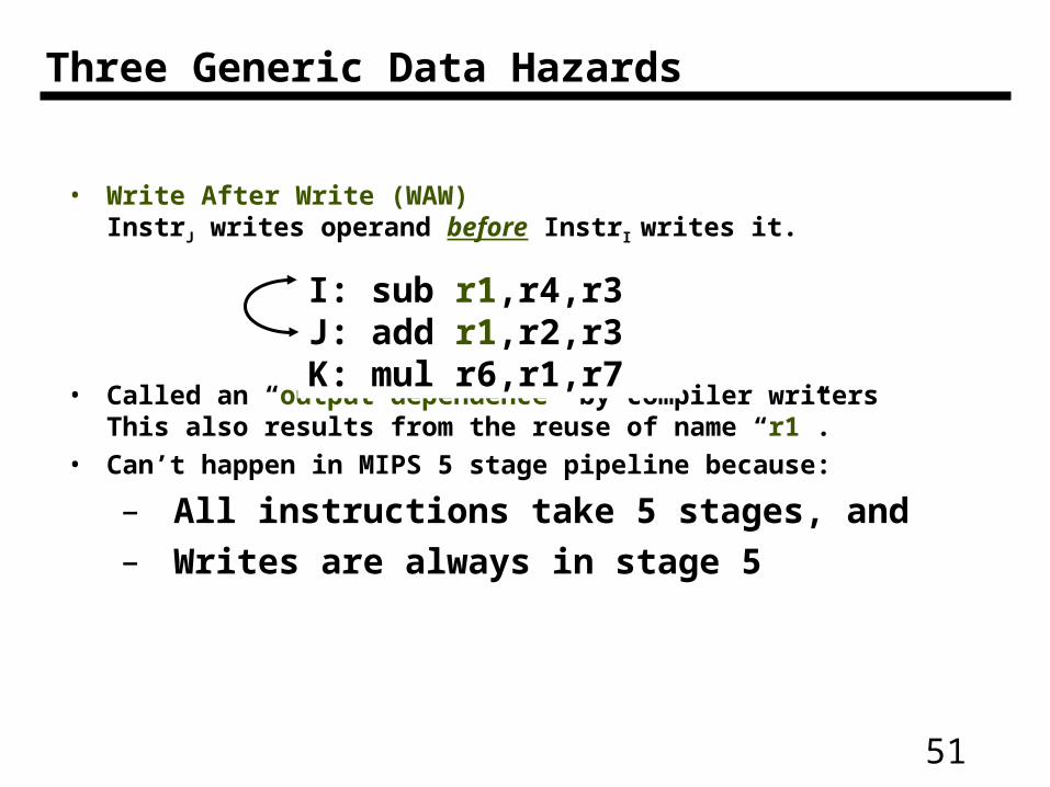
Three Generic Data Hazards
• Write After Write (WAW) InstrJ writes operand before InstrI writes it.
• Called an “output dependence” by compiler writersThis also results from the reuse of name “r1”.
• Can’t happen in MIPS 5 stage pipeline because:
– All instructions take 5 stages, and – Writes are always in stage 5
I: sub r1,r4,r3 J: add r1,r2,r3K: mul r6,r1,r7
52
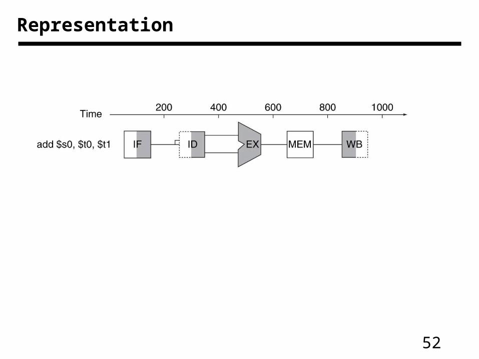
Representation
53
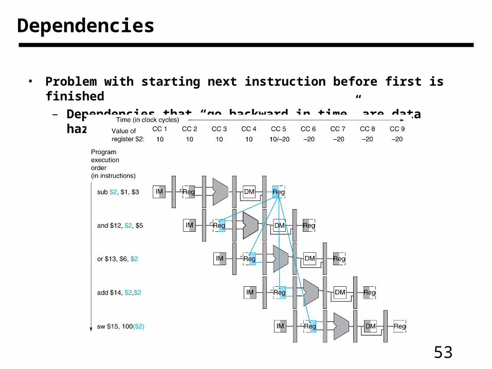
• Problem with starting next instruction before first is finished
– Dependencies that “go backward in time” are data hazards
Dependencies
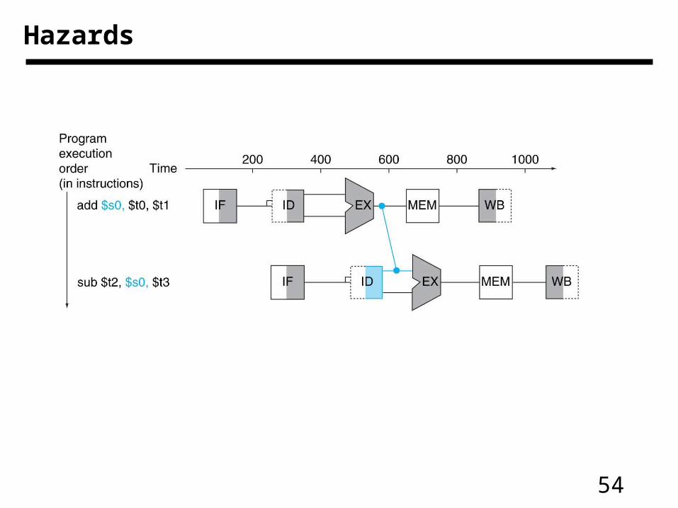
54
Hazards
55
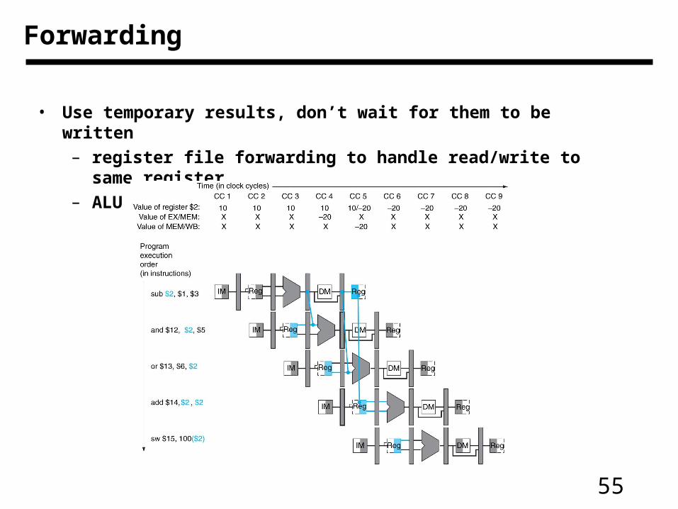
• Use temporary results, don’t wait for them to be written
– register file forwarding to handle read/write to same register
– ALU forwarding
Forwarding
56
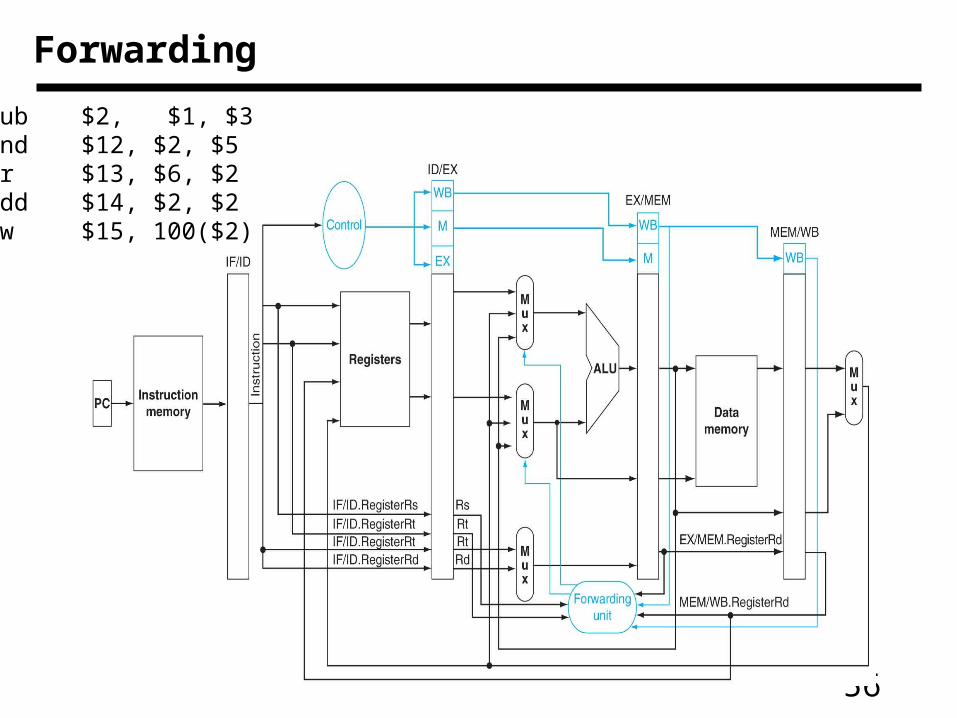
Forwarding
sub $2, $1, $3and $12, $2, $5or $13, $6, $2add $14, $2, $2sw $15, 100($2)
57
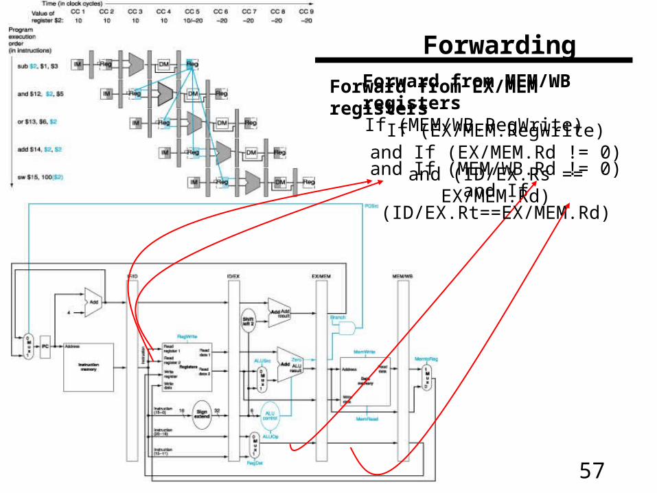
Forwarding
Forward from EX/MEM registersIf (EX/MEM.RegWrite)
and If (EX/MEM.Rd != 0)and (ID/EX.Rs == EX/MEM.Rd)
Forward from MEM/WB registers
If (MEM/WB.RegWrite) and If (MEM/WB.Rd != 0)
and If (ID/EX.Rt==EX/MEM.Rd)
58
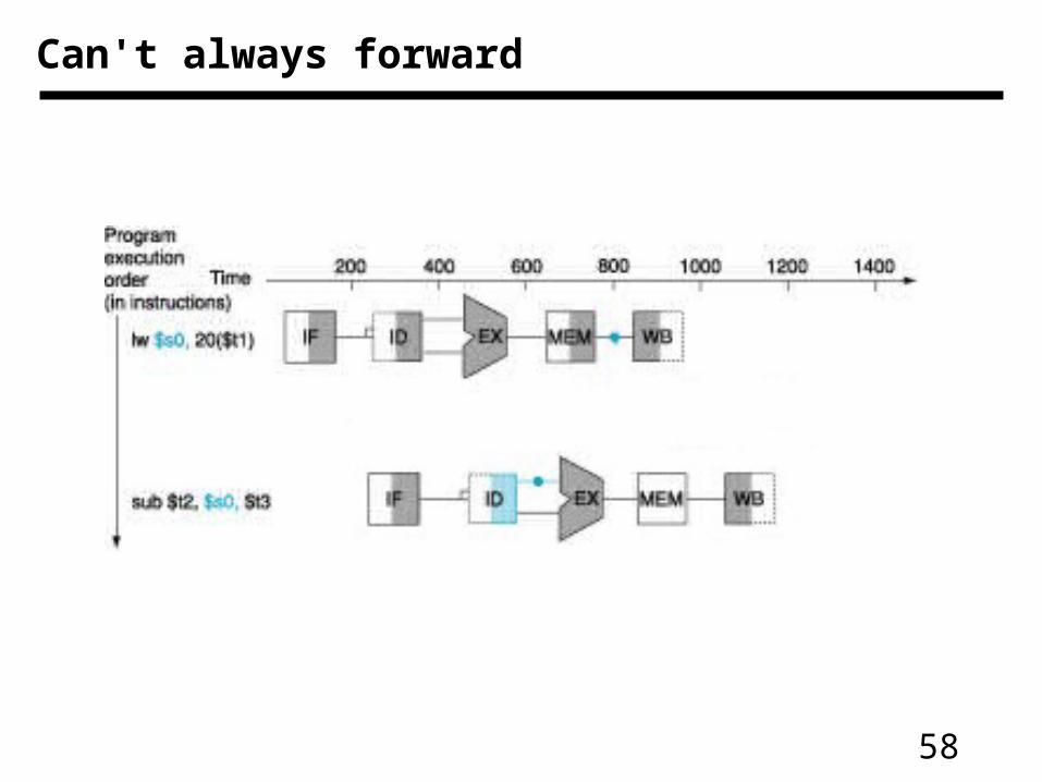
Can't always forward
59
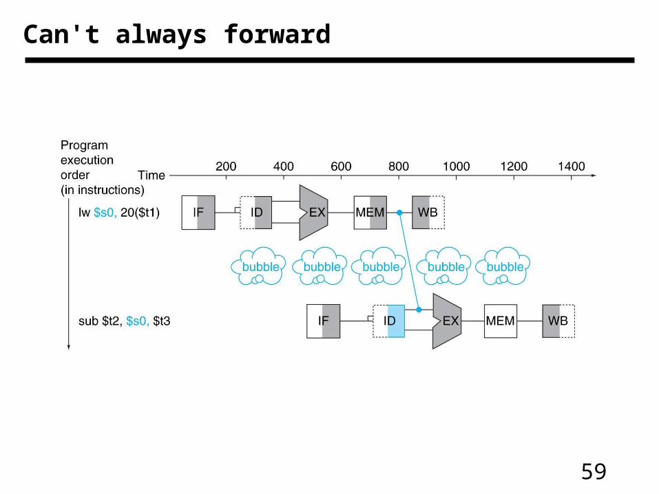
Can't always forward
60
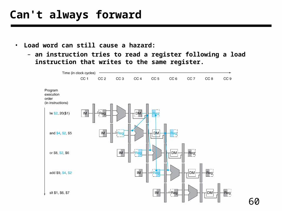
• Load word can still cause a hazard:– an instruction tries to read a register following a load instruction that
writes to the same register.
Can't always forward
61
lw $2, 20($1)
Programexecutionorder(in instructions)
and $4, $2, $5
or $8, $2, $6
add $9, $4, $2
slt $1, $6, $7
Reg
IM
Reg
Reg
IM DM
CC 1 CC 2 CC 3 CC 4 CC 5 CC 6Time (in clock cycles)
IM Reg DM RegIM
IM DM Reg
IM DM Reg
CC 7 CC 8 CC 9 CC 10
DM Reg
RegReg
Reg
bubble
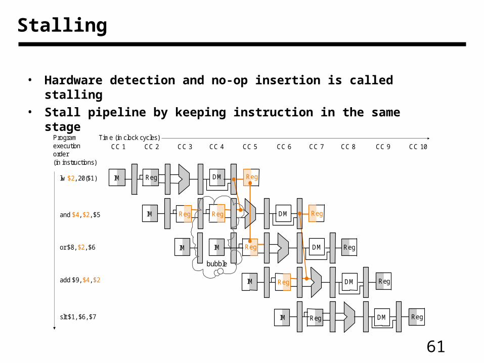
Stalling
• Hardware detection and no-op insertion is called stalling
• Stall pipeline by keeping instruction in the same stage
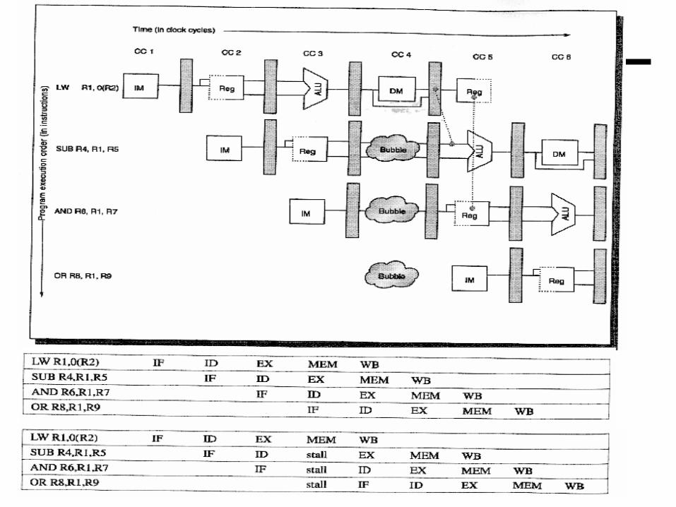
62
63
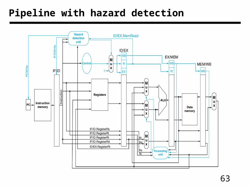
Pipeline with hazard detection
64
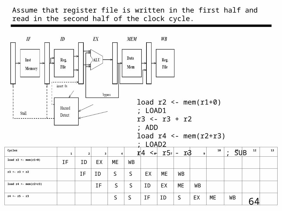
Assume that register file is written in the first half and read in the second half of the clock cycle.
Cycles 1 2 3 4 5 6 7 8 9 10 11 12 13
load r2 <- mem(r1+0)
r3 <- r3 + r2
load r4 <- mem(r2+r3)
r4 <- r5 - r3
IF ID EX ME WB
IF ID S S EX ME WB
IF S S ID EX ME WB
IF ID S EX ME WBS S
load r2 <- mem(r1+0) ; LOAD1r3 <- r3 + r2 ; ADDload r4 <- mem(r2+r3) ; LOAD2r4 <- r5 - r3 ; SUB
65
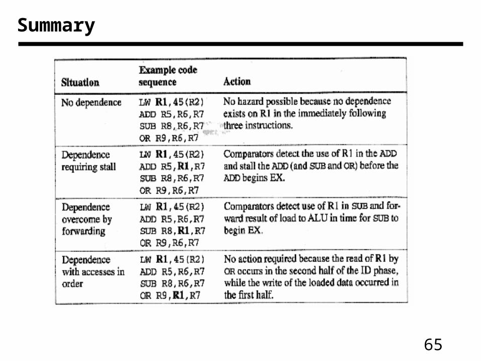
Summary
66
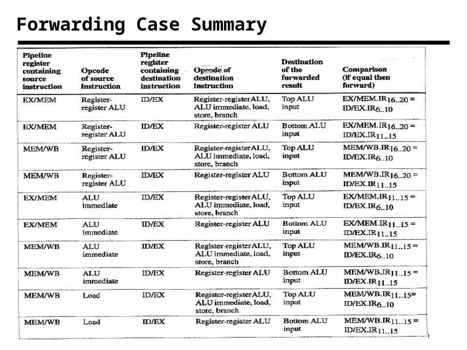
Forwarding Case Summary
67
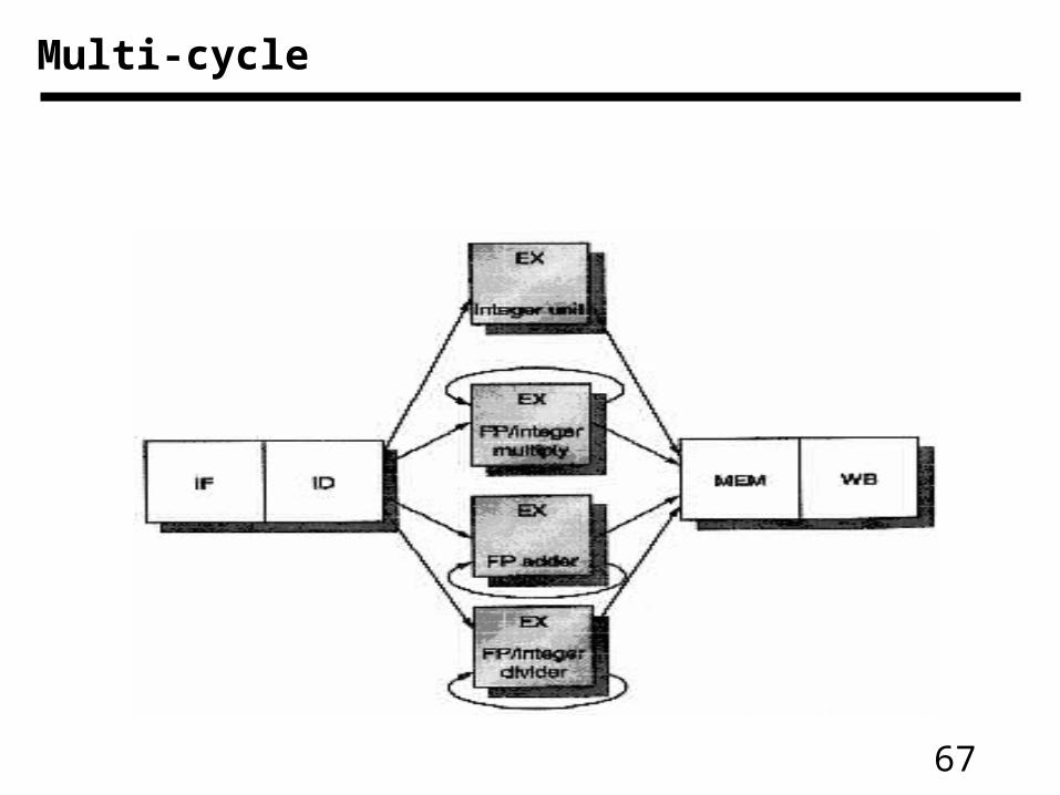
Multi-cycle
68
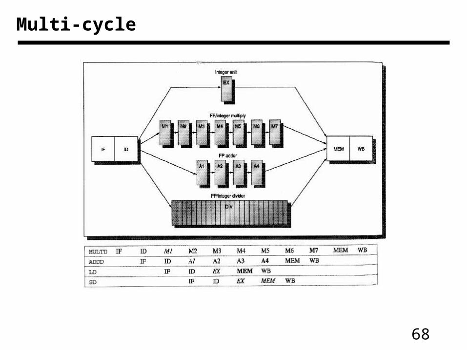
Multi-cycle
69
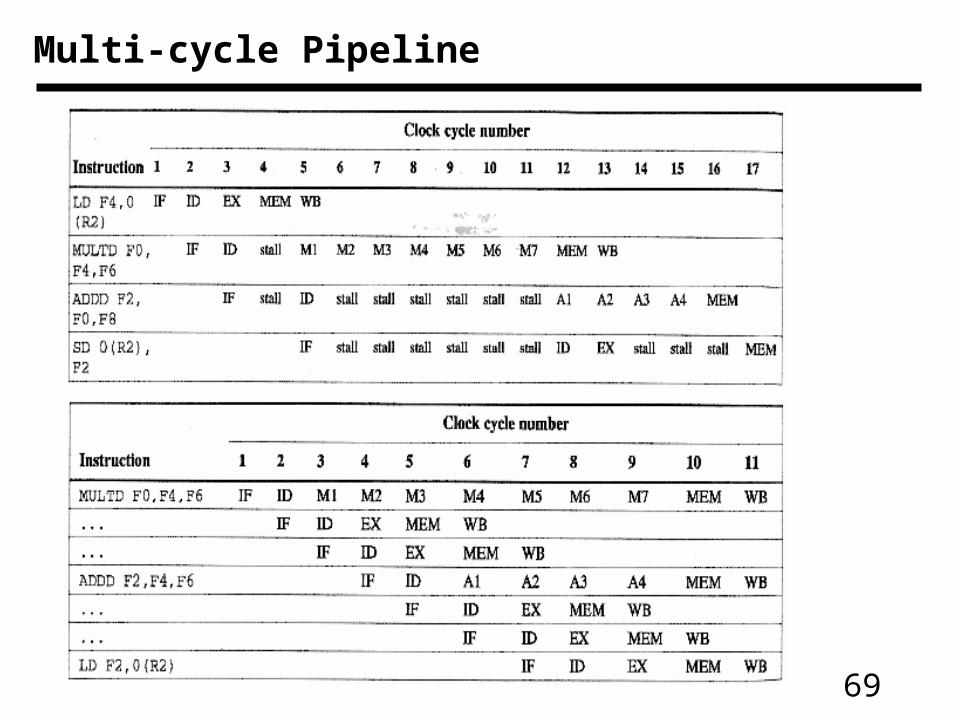
Multi-cycle Pipeline
70
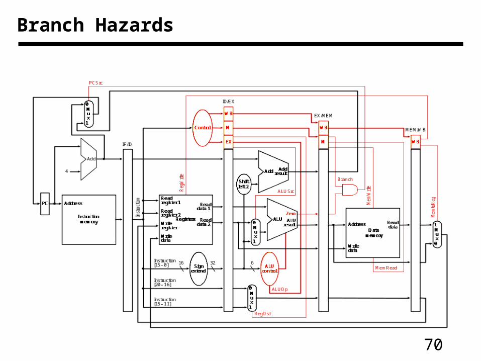
Branch Hazards
71
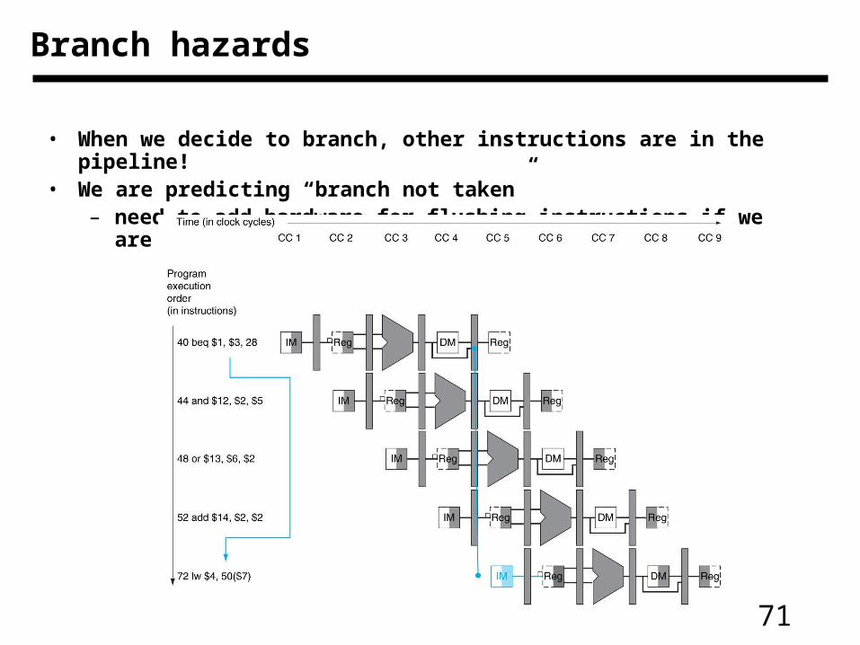
• When we decide to branch, other instructions are in the pipeline!• We are predicting “branch not taken”
– need to add hardware for flushing instructions if we are wrong
Branch hazards
72
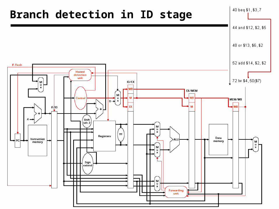
Branch detection in ID stage
73
Solution to control hazards
• Branch prediction
– We are predicting “branch not taken”
– Need to add hardware for flushing instructions if we are wrong
• Reduce branch penalty
– By advancing the branch decision to ID stage
– Compare the data read from two registers read in ID stage
– Comparison for equality is a simpler design! (Why?)
– Still need to flush instruction in IF stage
• Make the hazard into a feature!
– Delayed branch slot - Always execute instruction following branch
74
Branch Prediction
• Sophisticated Techniques:
– A “branch target buffer” to help us look up the destination
– Correlating predictors that base prediction on global behaviorand recently executed branches (e.g., prediction for a specific
branch instruction based on what happened in previous branches)
– Tournament predictors that use different types of prediction strategies and keep track of which one is performing best.
– A “branch delay slot” which the compiler tries to fill with a useful instruction (make the one cycle delay part of the ISA)
• Branch prediction is especially important because it enables other more advanced pipelining techniques to be effective!
• Modern processors predict correctly 95% of the time!
75
Four Branch Hazard Alternatives
#1: Stall until branch direction is clear: branch penalty is fixed and can not be reduced by software (this is the example of MIPS)
#2: Predict Branch Not Taken (treat every branch as not taken)– Execute successor instructions in sequence– “flush” instructions in pipeline if branch actually taken– 47% MIPS branches not taken on average– PC+4 already calculated, so use it to get next instruction
76
Four Branch Hazard Alternatives:
#3: Predict Branch Taken (treat every branch as taken)As soon as the branch is decoded and the target address is
computed, we assume the branch is taken and begin fetching and executing at the target address.
– 53% MIPS branches taken on average– Because in our MIPS pipeline we don’t
know the target address any earlier than we know the branch outcome, there is no advantage in this approach for MIPS.
– MIPS still incurs 1 cycle branch penalty• Other machines: branch target known before
outcome
77
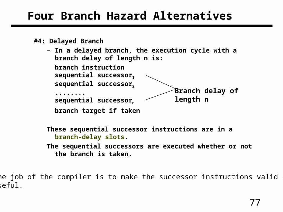
Four Branch Hazard Alternatives
#4: Delayed Branch– In a delayed branch, the execution cycle with a branch delay
of length n is:
branch instructionsequential successor1
sequential successor2
........sequential successorn
branch target if taken
These sequential successor instructions are in a branch-delay slots.
The sequential successors are executed whether or not the branch is taken.
Branch delay of length n
The job of the compiler is to make the successor instructions valid and useful.
78
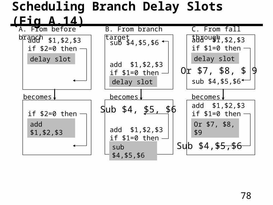
Scheduling Branch Delay Slots (Fig A.14)
add $1,$2,$3if $2=0 then
delay slot
A. From before branch B. From branch target C. From fall through
add $1,$2,$3if $1=0 thendelay slot
add $1,$2,$3if $1=0 then
delay slot
sub $4,$5,$6
sub $4,$5,$6
becomes becomes becomes if $2=0 then
add $1,$2,$3add $1,$2,$3if $1=0 thensub $4,$5,$6
add $1,$2,$3if $1=0 then
Or $7, $8, $9
Sub $4, $5, $6
Or $7, $8, $ 9
Sub $4,$5,$6
79
Delayed Branch
• Where to get instructions to fill branch delay slot?
– Before branch instruction: this is the best choice if feasible.
– From the target address: only valuable when branch taken
– From fall through: only valuable when branch not taken
• Compiler effectiveness for single branch delay slot:
– Fills about 60% of branch delay slots
– About 80% of instructions executed in branch delay slots useful in computation
– About 50% (60% x 80%) of slots usefully filled
• Delayed Branch downside: As processor go to deeper pipelines and multiple issue, the branch delay grows and need more than one delay slot
– Delayed branching has lost popularity compared to more expensive but more flexible dynamic approaches
– Growth in available transistors has made dynamic approaches relatively cheaper
80
Improving Performance
• Try and avoid stalls! E.g., reorder these instructions:
lw $t0, 0($t1)lw $t2, 4($t1)sw $t2, 0($t1)sw $t0, 4($t1)
• Dynamic Pipeline Scheduling
– Hardware chooses which instructions to execute next
– Will execute instructions out of order (e.g., doesn’t wait for a dependency to be resolved, but rather keeps going!)
– Speculates on branches and keeps the pipeline full (may need to rollback if prediction incorrect)
• Trying to exploit instruction-level parallelism
81
Advanced Pipelining
• Increase the depth of the pipeline
• Start more than one instruction each cycle (multiple issue)
• Loop unrolling to expose more ILP (better scheduling)
• “Superscalar” processors
– DEC Alpha 21264: 9 stage pipeline, 6 instruction issue
• All modern processors are superscalar and issue multiple instructions usually with some limitations (e.g., different “pipes”)
82
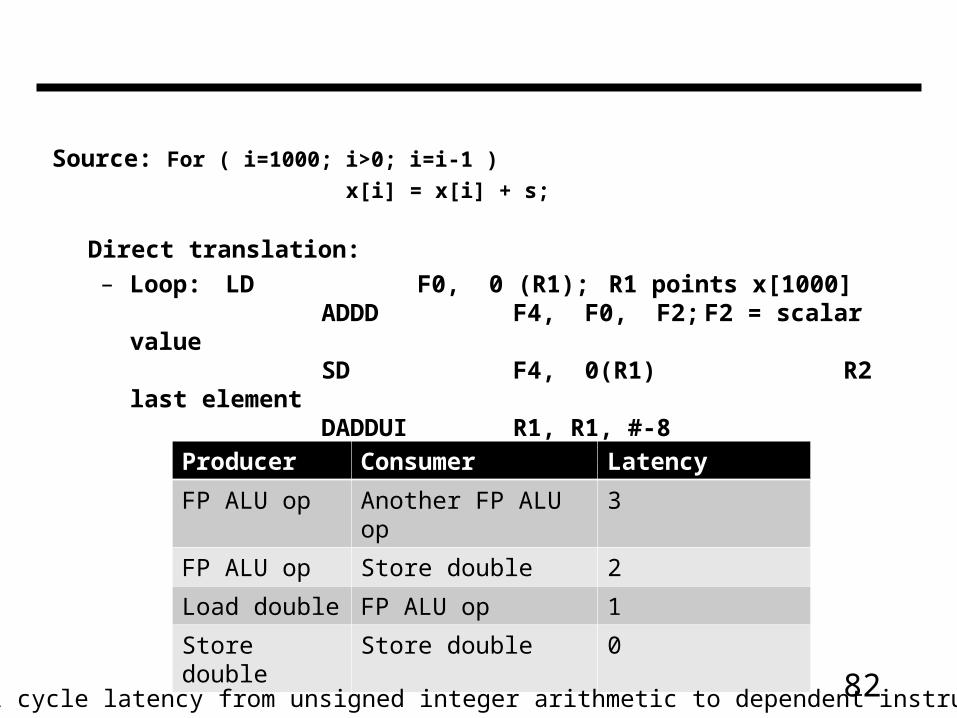
Source: For ( i=1000; i>0; i=i-1 )
x[i] = x[i] + s;
Direct translation:
– Loop: LD F0, 0 (R1); R1 points x[1000]ADDD F4, F0, F2; F2 = scalar
valueSD F4, 0(R1) R2 last
elementDADDUI R1, R1, #-8BNE R1, R2, loop;Producer Consumer Latency
FP ALU op Another FP ALU op 3
FP ALU op Store double 2
Load double FP ALU op 1
Store double Store double 0
Assume 1 cycle latency from unsigned integer arithmetic to dependent instruction
83
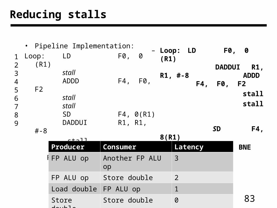
Reducing stalls
• Pipeline Implementation:
Loop: LD F0, 0 (R1)stallADDD F4, F0, F2stallstallSD F4, 0(R1)DADDUI R1, R1, #-8
stallBNE R1, R2,
loopstall
– Loop: LD F0, 0 (R1)DADDUI R1,
R1, #-8 ADDD F4, F0, F2
stall
stall
SD F4, 8(R1)
BNE R1, R2, Loop
Producer Consumer Latency
FP ALU op Another FP ALU op 3
FP ALU op Store double 2
Load double FP ALU op 1
Store double Store double 0
123456789
84
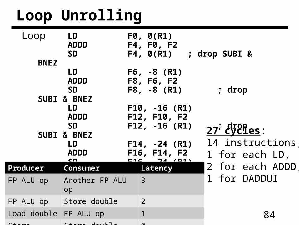
LD F0, 0(R1)ADDD F4, F0, F2SD F4, 0(R1) ; drop SUBI &
BNEZLD F6, -8 (R1)ADDD F8, F6, F2SD F8, -8 (R1) ; drop SUBI &
BNEZLD F10, -16 (R1)ADDD F12, F10, F2SD F12, -16 (R1) ; drop SUBI &
BNEZLD F14, -24 (R1)ADDD F16, F14, F2SD F16, -24 (R1) DADDUI R1, R1, #-32BNE R1, R2, Loop
Loop UnrollingLoop
Producer Consumer Latency
FP ALU op Another FP ALU op 3
FP ALU op Store double 2
Load double FP ALU op 1
Store double Store double 0
27 cycles: 14 instructions,1 for each LD, 2 for each ADDD,1 for DADDUI
85
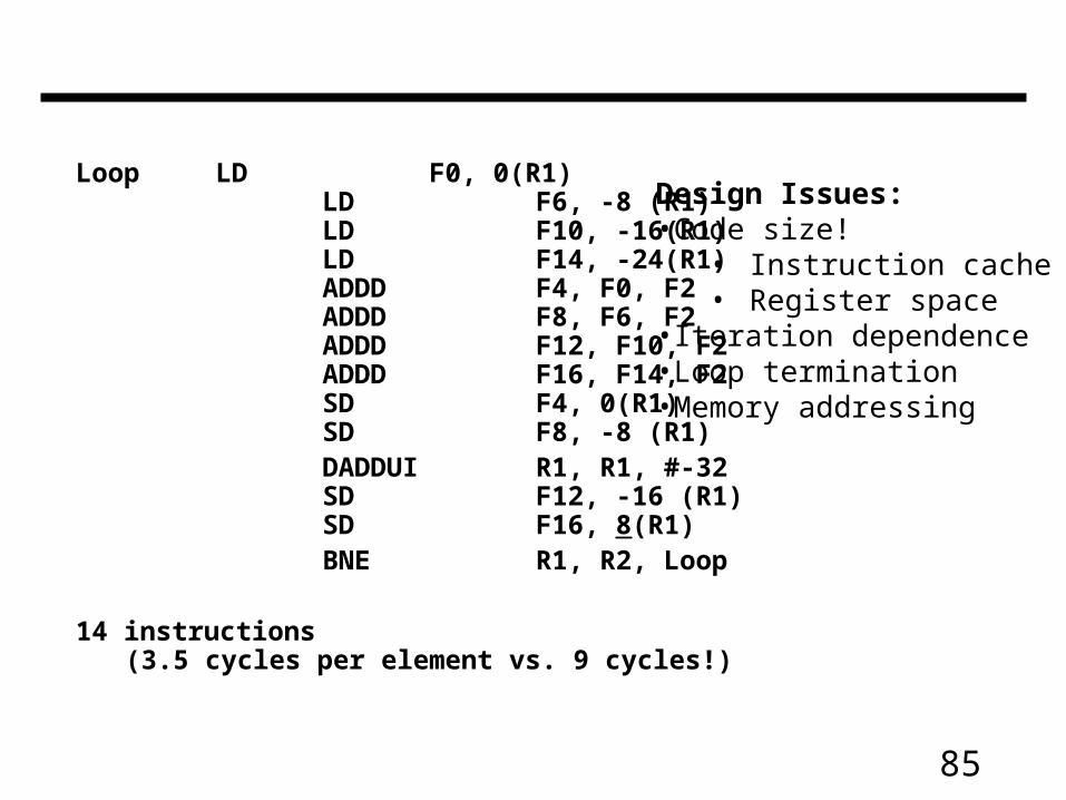
Loop LD F0, 0(R1)LD F6, -8 (R1)LD F10, -16(R1)LD F14, -24(R1)ADDD F4, F0, F2
ADDD F8, F6, F2 ADDD F12, F10, F2 ADDD F16, F14, F2
SD F4, 0(R1) SD F8, -8 (R1)
DADDUI R1, R1, #-32 SD F12, -16 (R1)
SD F16, 8(R1)BNE R1, R2, Loop
14 instructions (3.5 cycles per element vs. 9 cycles!)
Design Issues:•Code size!
• Instruction cache• Register space
•Iteration dependence•Loop termination•Memory addressing
86
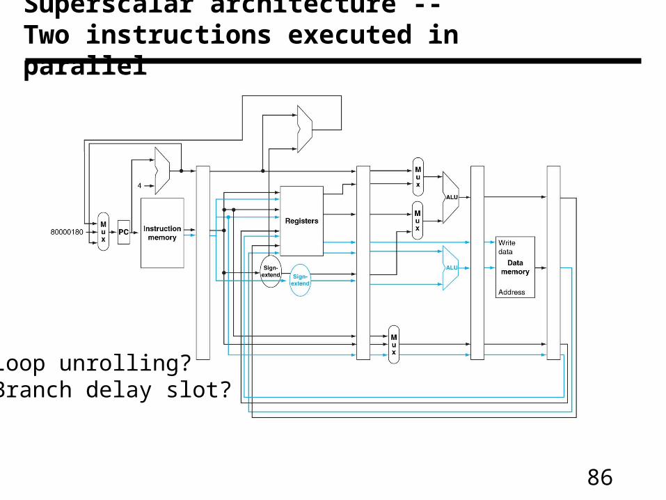
Superscalar architecture -- Two instructions executed in parallel
Loop unrolling?Branch delay slot?
87
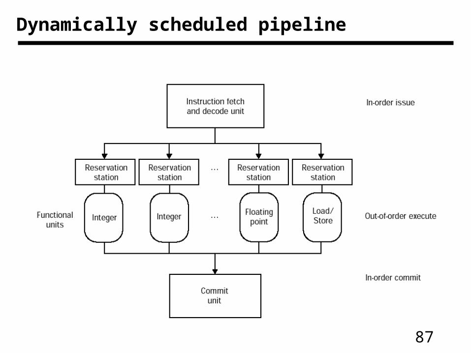
Dynamically scheduled pipeline
88
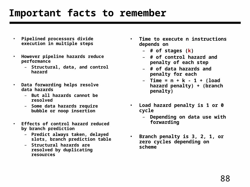
Important facts to remember
• Pipelined processors divide execution in multiple steps
• However pipeline hazards reduce performance
– Structural, data, and control hazard
• Data forwarding helps resolve data hazards
– But all hazards cannot be resolved
– Some data hazards require bubble or noop insertion
• Effects of control hazard reduced by branch prediction
– Predict always taken, delayed slots, branch prediction table
– Structural hazards are resolved by duplicating resources
• Time to execute n instructions depends on
– # of stages (k)– # of control hazard and penalty of
each step– # of data hazards and penalty for
each– Time = n + k - 1 + (load hazard
penalty) + (branch penalty)
• Load hazard penalty is 1 or 0 cycle – Depending on data use with
forwarding
• Branch penalty is 3, 2, 1, or zero cycles depending on scheme
89
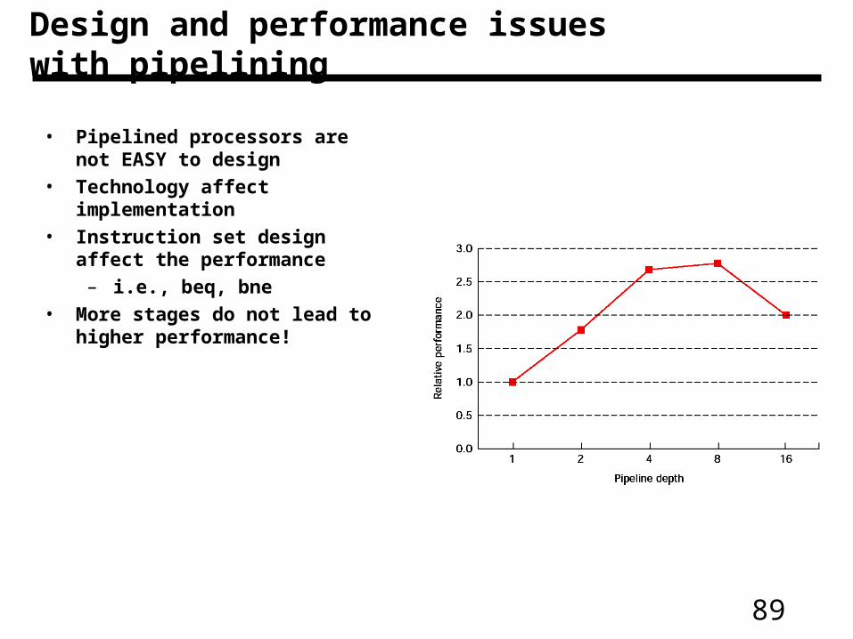
Design and performance issues with pipelining
• Pipelined processors are not EASY to design
• Technology affect implementation• Instruction set design affect the
performance– i.e., beq, bne
• More stages do not lead to higher performance!