Embed Size (px)
Citation preview
1
ECE 3336 Introduction to Circuits & Electronics
Lecture Set #7Inductors and Capacitors
Fall 2012,TUE&TH 5:30-7:00pmDr. Wanda Wosik
Notes developed by Dr. Dave Shattuck

2
Overview of this Part Inductors and Capacitors
In this part, we will cover the following topics:• Defining equations for inductors and capacito
rs• Power and energy storage in inductors and c
apacitors• Parallel and series combinations• Basic Rules for inductors and capacitors
3
Basic Elements, Review
We are now going to pick up the remaining basic circuit elements that we will be covering in these modules.

4
Circuit Elements• In circuits, we think about basic circuit
elements that are the basic “building blocks” of our circuits. This is similar to what we do in Chemistry with chemical elements like oxygen or nitrogen.
• A circuit element cannot be broken down or subdivided into other circuit elements.
• A circuit element can be defined in terms of the behavior of the voltage and current at its terminals.
5
The 5 Basic Circuit ElementsThere are 5 basic circuit elements:1. Voltage sources2. Current sources3. Resistors4. Inductors5. CapacitorsWe defined the first three elements in a
previous module. We will now introduce inductors or capacitors.
6
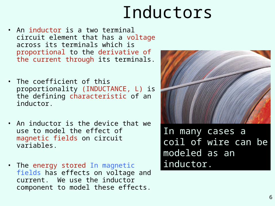
Inductors• An inductor is a two terminal circuit
element that has a voltage across its terminals which is proportional to the derivative of the current through its terminals.
• The coefficient of this proportionality (INDUCTANCE, L) is the defining characteristic of an inductor.
• An inductor is the device that we use to model the effect of magnetic fields on circuit variables.
• The energy stored In magnetic fields has effects on voltage and current. We use the inductor component to model these effects.
In many cases a coil of wire can be modeled as an inductor.
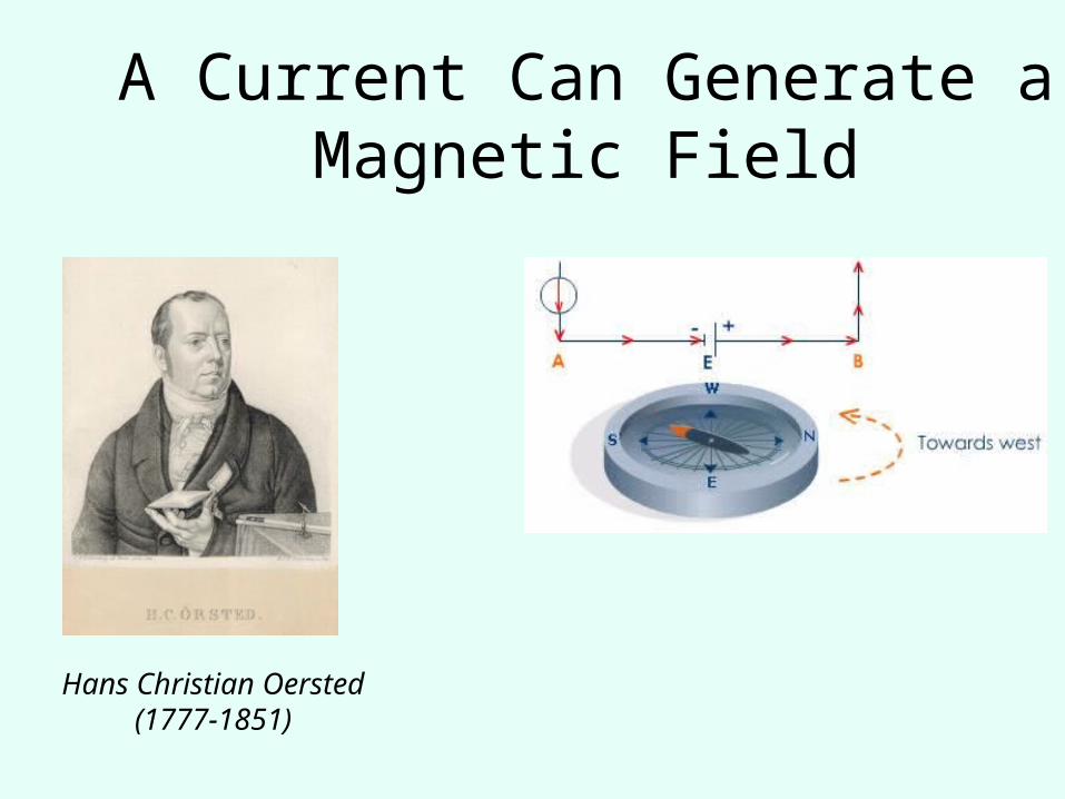
A Current Can Generate a Magnetic Field
Hans Christian Oersted(1777-1851)

8
• http://hyperphysics.phy-astr.gsu.edu/hbase/forces/funfor.html#c3
• http://hyperphysics.phy-astr.gsu.edu/hbase/magnetic/magfie.html#c1
• http://hyperphysics.phy-astr.gsu.edu/hbase/magnetic/amplaw.html#c1
• http://hyperphysics.phy-astr.gsu.edu/hbase/electric/elefie.html#c1
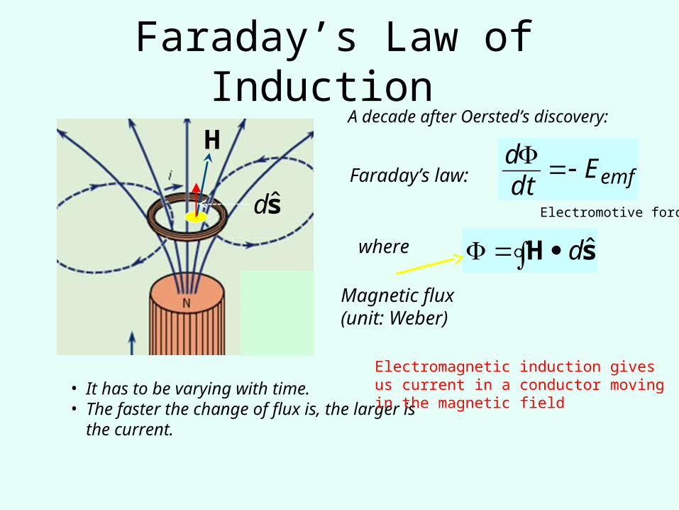
Faraday’s Law of Induction
emfEdtd
Faraday’s law:
sH ˆd
where
H
Magnetic flux (unit: Weber)
• It has to be varying with time.• The faster the change of flux is, the
larger is the current.
sd
Electromagnetic induction gives us current in a conductor moving in the magnetic field
Electromotive force
A decade after Oersted’s discovery:
10
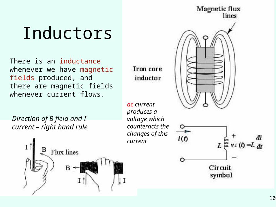
Inductors
There is an inductance whenever we have magnetic fields produced, and there are magnetic fields whenever current flows.
ac current produces a voltage which counteracts the changes of this current
Direction of B field and I current – right hand rule
11
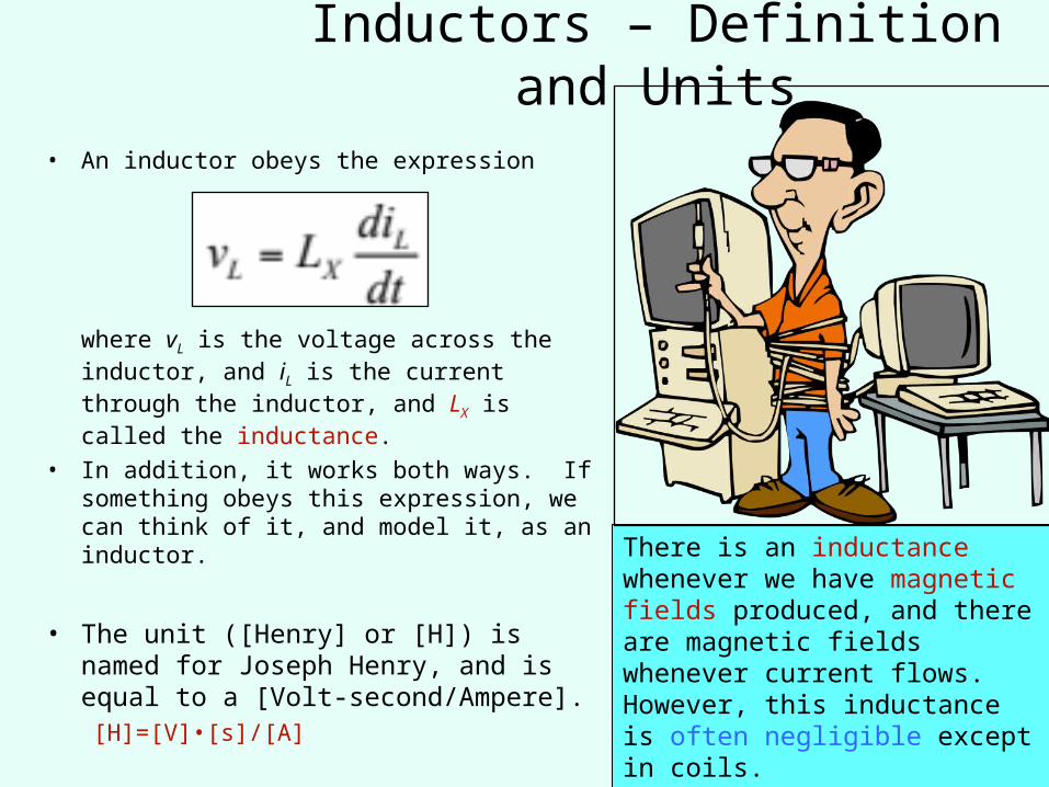
• An inductor obeys the expression
where vL is the voltage across the inductor, and iL is the current through the inductor, and LX is called the inductance.
• In addition, it works both ways. If something obeys this expression, we can think of it, and model it, as an inductor.
• The unit ([Henry] or [H]) is named for Joseph Henry, and is equal to a [Volt-second/Ampere].[H]=[V]•[s]/[A]
Inductors – Definition and Units
There is an inductance whenever we have magnetic fields produced, and there are magnetic fields whenever current flows. However, this inductance is often negligible except in coils.

12
Schematic Symbol for InductorsThe schematic symbol that we use for
inductors is shown here.The schematic symbol can be labeled either with a variable, like LX, or a value, with some number, and units. An example might be 390[mH].
13
Inductor Polarities
• Previously, we have emphasized the important of reference polarities of current sources and voltages sources. There is no corresponding polarity to an inductor.
• As in Resistors.
• And as for resistor, direction matters with respect to the voltage and current in the passive sign convention.

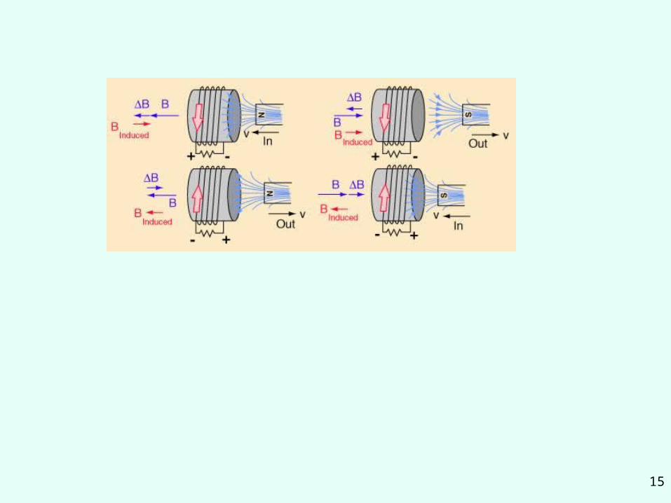
The direction of currents induced by magnetic field
Heinrich Friedrich Emil Lenz1804 –1865
The induced current creates a magnetic field opposing the change of the inducing magnetic field
The rule of resistance to change
15

16
Passive and Active Sign Convention for Inductors
The sign of the equation that we use for inductors depends on whether we have used the passive sign convention or the active sign convention.
Passive Sign Convention Active Sign Convention
17
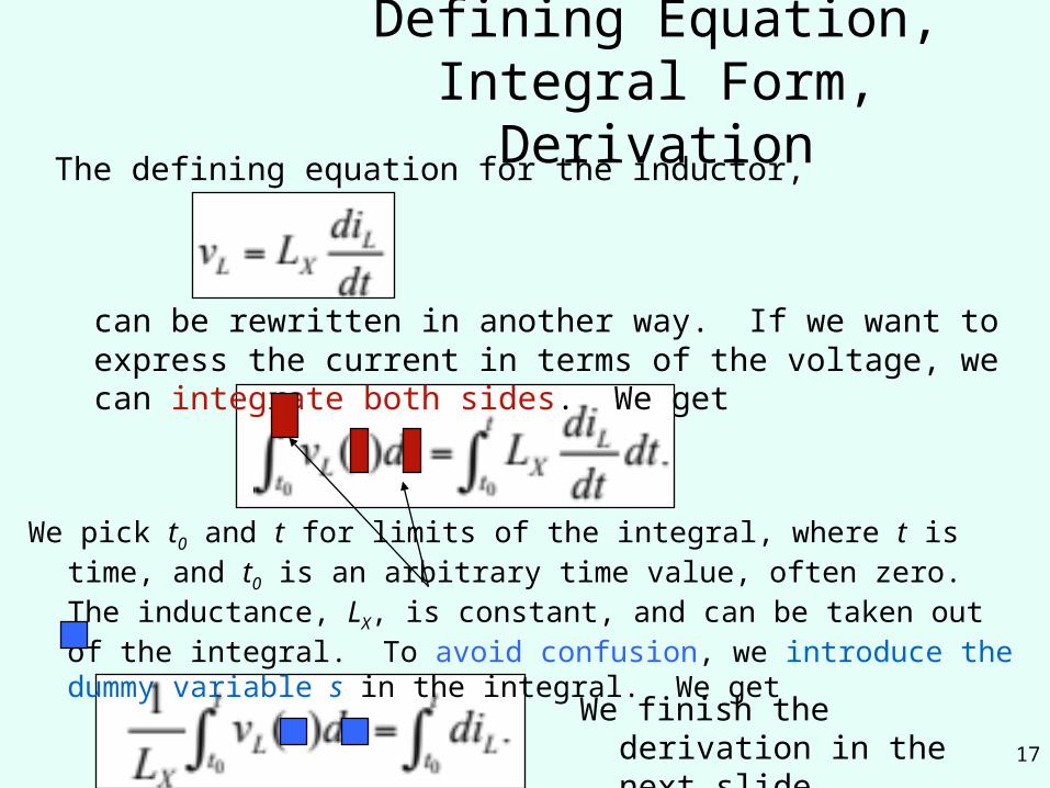
Defining Equation, Integral Form, Derivation
The defining equation for the inductor,
can be rewritten in another way. If we want to express the current in terms of the voltage, we can integrate both sides. We get
We pick t0 and t for limits of the integral, where t is time, and t0 is an arbitrary time value, often zero. The inductance, LX, is constant, and can be taken out of the integral. To avoid confusion, we introduce the dummy variable s in the integral. We get
We finish the derivation in the next slide.

18
We can take this equation and perform the integral on the right hand side. When we do this we get
Thus, we can solve for iL(t), and we have two defining equations for the inductor,
Defining Equations for Inductors
and
Remember that both of these are defined for the passive sign convention for iL and vL. If not, then we need a negative sign in these equations.
Initial conditions
19
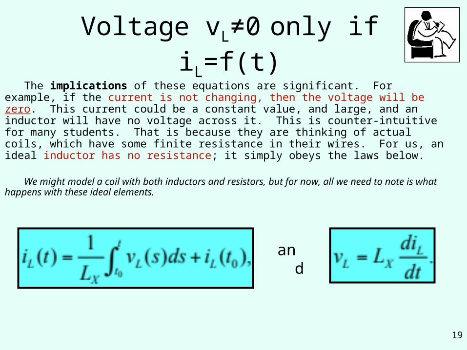
Voltage vL≠0 only if iL=f(t)
The implications of these equations are significant. For example, if the current is not changing, then the voltage will be zero. This current could be a constant value, and large, and an inductor will have no voltage across it. This is counter-intuitive for many students. That is because they are thinking of actual coils, which have some finite resistance in their wires. For us, an ideal inductor has no resistance; it simply obeys the laws below.
We might model a coil with both inductors and resistors, but for now, all we need to note is what happens with these ideal elements.
and

20
Current Change is Limited so
Another implication is that we cannot change the current through an inductor instantaneously. If we were to make such a change, the derivative of current with respect to time would be infinity, and the voltage would have to be infinite. Since it is not possible to have an infinite voltage, it must be impossible to change the current through an inductor instantaneously.
and
But large voltages can be produced
21
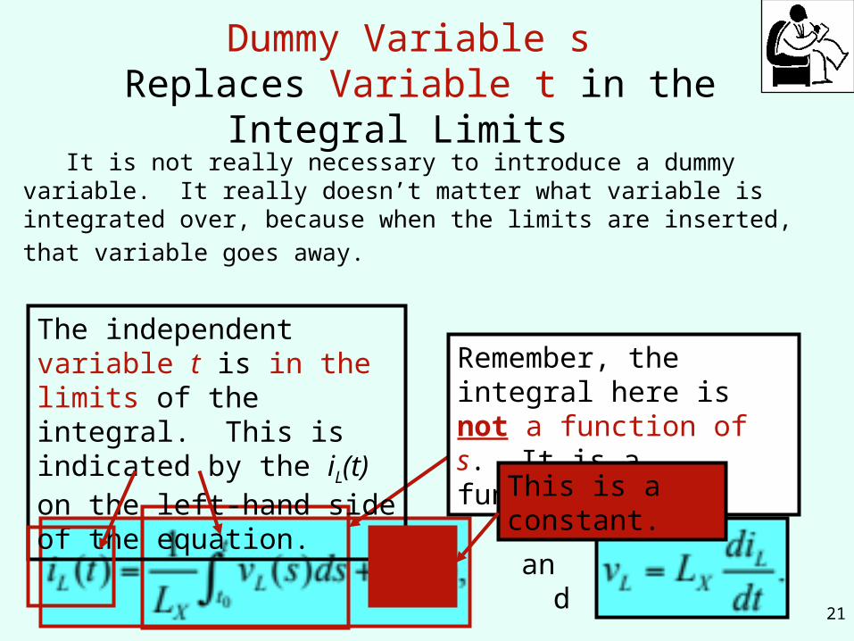
Dummy Variable s Replaces Variable t in the Integral Limits It is not really necessary to introduce a dummy variable. It really does
n’t matter what variable is integrated over, because when the limits are
inserted, that variable goes away.
and
The independent variable t is in the limits of the integral. This is indicated by the iL(t) on the left-hand side of the equation.
Remember, the integral here is not a function of s. It is a function of t.
This is a constant.
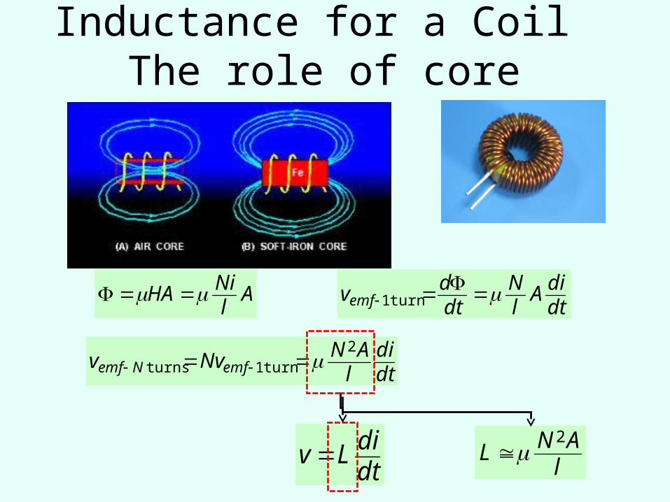
Inductance for a Coil The role of core
lANL
2
AlNiHA
dtdiA
lN
dtdvemf turn1
dtdi
lANNvv emfNemf
2
turn1turns
dtdiLv

23
Energy in Inductors, DerivationWe can find the energy stored in the magnetic field associated with the
inductor. First, we note that the power is voltage times current, as it has always been.
Now, we can multiply each side by dt, and integrate both sides to get
We need limits. We know that when the current is zero, there is no magnetic field, and therefore there can be no energy in the magnetic field. That allowed us to use 0 for the lower limits. The upper limits came since we will have the energy stored, wL, for a given value of current, iL.
24
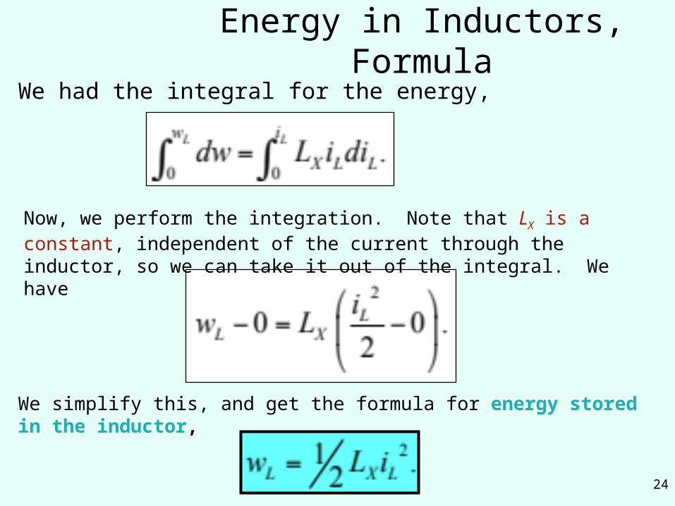
Energy in Inductors, FormulaWe had the integral for the energy,
Now, we perform the integration. Note that LX is a constant, independent of the current through the inductor, so we can take it out of the integral. We have
We simplify this, and get the formula for energy stored in the inductor,

25
Series Inductors Equivalent CircuitsTwo series
inductors, L1 and L2, can be replaced with an equivalent circuit with a single inductor LEQ, as long as
iL1(t)=iL2(t)=iLEQ(t)
(∑Li is as for resistors)
Obtained from KVLvLEQ(t)=VL1(t)+VL2(t)

26
More than 2 Series InductorsThis rule can be
extended to more than two series inductors. In this case, for N series inductors, we have
(∑Li reminds of ∑Ri for resistors)

27
Series Inductors Equivalent Circuits: A ReminderTwo series inductors,
L1 and L2, can be replaced with an equivalent circuit with a single inductor LEQ, as long as
Remember that these two equivalent circuits are equivalent only with respect to the circuit connected to them.
(In yellow here.)
28
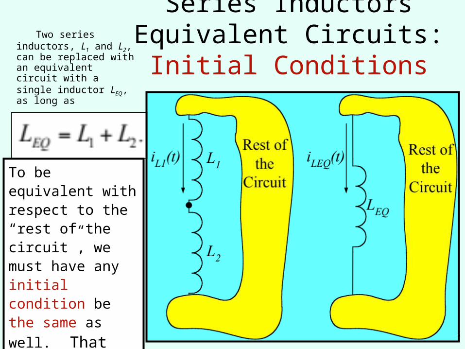
Series Inductors Equivalent Circuits: Initial Conditions
Two series inductors, L1 and L2, can be replaced with an equivalent circuit with a single inductor LEQ, as long as
To be equivalent with respect to the “rest of the circuit”, we must have any initial condition be
the same as well. That is,
iL1(t0) must equal
iLEQ(t0).
29
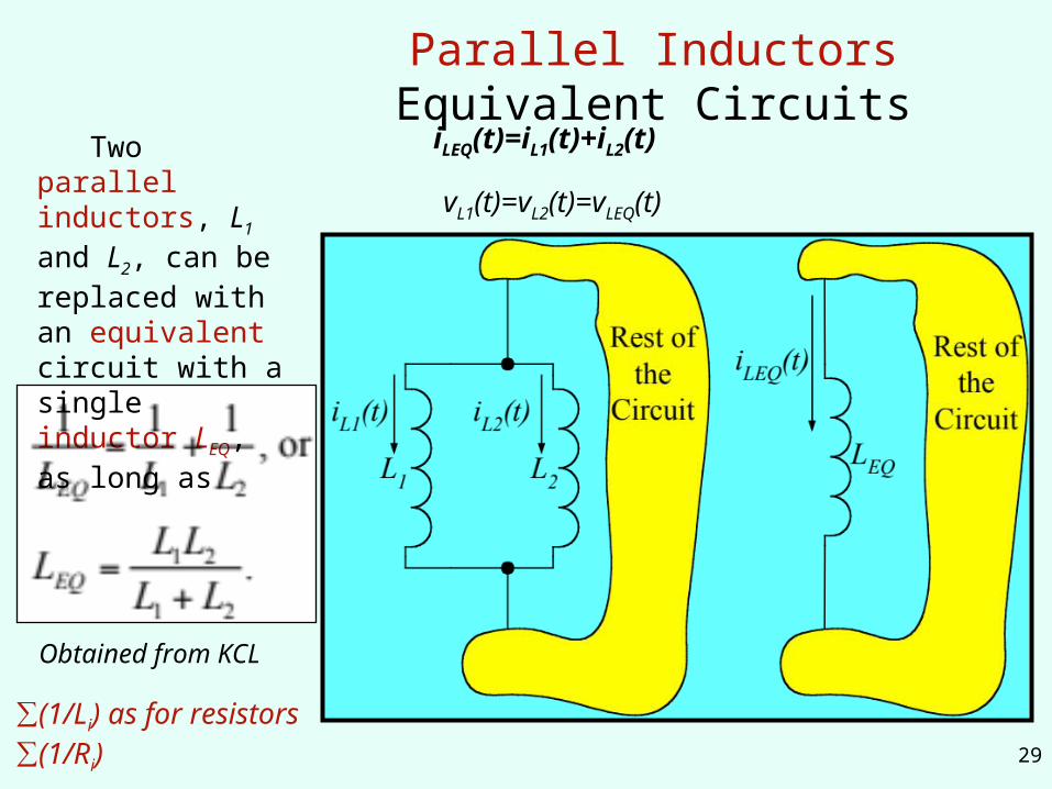
Parallel Inductors Equivalent Circuits
Two parallel inductors, L1 and L2, can be replaced with an equivalent circuit with a single inductor LEQ, as long as
Obtained from KCL
∑(1/Li) as for resistors ∑(1/Ri)
iLEQ(t)=iL1(t)+iL2(t)
vL1(t)=vL2(t)=vLEQ(t)

30
More than 2 Parallel Inductors
This rule can be extended to more than two parallel inductors. In this case, for N parallel inductors, we have
The product over sum rule only works for two inductors.
Analogy to RESISTORS
31
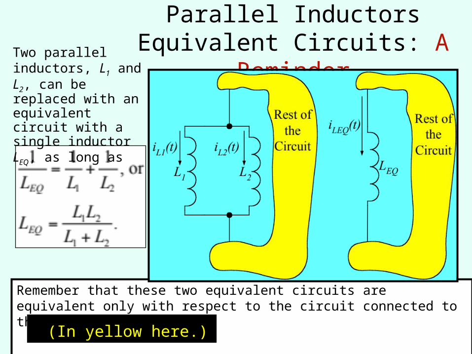
Parallel Inductors Equivalent Circuits: A Reminder
Remember that these two equivalent circuits are equivalent only with respect to the circuit connected to them.
Two parallel inductors, L1 and L2, can be replaced with an equivalent circuit with a single inductor LEQ, as long as
(In yellow here.)
32
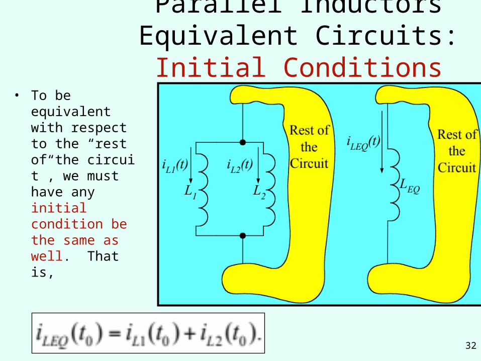
Parallel Inductors Equivalent Circuits: Initial Conditions
• To be equivalent with respect to the “rest of the circuit”, we must have any initial condition be the same as well. That is,

33
Notes1.We took some mathematical liberties in this derivation. For example, we do
not really multiply both sides by dt, but the results that we obtain are correct here. 2.Note that the energy is a function of the current squared, which will be
positive. We will assume that our inductance is also positive, and clearly ½ is positive. So, the energy stored in the magnetic field of an inductor will be positive.
3.These three equations are useful, and should be learned or written down.
Go back to Overview
slide.