Embed Size (px)
Citation preview

11
Development of Performance Testing Methods for Dynamic Frequency Selection (DFS) 5-GHz Wireless
Access Systems (WAS)
Frank Sanders
Chief, Telecommunications Theory Division
NTIA Institute for Telecommunication Sciences
U.S. Department of [email protected]
International Symposium on Advanced Radio Technologies 2006
March 8, 2006
22
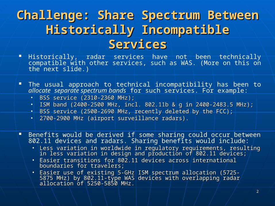
Challenge: Share Spectrum Between Challenge: Share Spectrum Between Historically Incompatible ServicesHistorically Incompatible Services
Historically, radar services have not been technically compatible with other services, such as WAS. (More on this on the next slide.)
The usual approach to technical incompatibility has been to allocate separate spectrum bands for such services. For example:• BSS service (2310-2360 MHz);BSS service (2310-2360 MHz);• ISM band (2400-2500 MHz, incl. 802.11b & g in 2400-2483.5 ISM band (2400-2500 MHz, incl. 802.11b & g in 2400-2483.5
MHz);MHz);• BSS service (2500-2690 MHz, recently deleted by the FCC);BSS service (2500-2690 MHz, recently deleted by the FCC);• 2700-2900 MHz (airport surveillance radars).2700-2900 MHz (airport surveillance radars).
Benefits would be derived if some sharing could occur between 802.11 devices and radars. Sharing benefits would include:• Less variation in worldwide in regulatory requirements, Less variation in worldwide in regulatory requirements,
resulting in less variation in design and production of resulting in less variation in design and production of 802.11 devices;802.11 devices;
• Easier transitions for 802.11 devices across international Easier transitions for 802.11 devices across international boundaries for travelers;boundaries for travelers;
• Easier use of existing 5-GHz ISM spectrum allocation (5725-Easier use of existing 5-GHz ISM spectrum allocation (5725-5875 MHz) by 802.11-type WAS devices with overlapping radar 5875 MHz) by 802.11-type WAS devices with overlapping radar allocation of 5250-5850 MHz.allocation of 5250-5850 MHz.

33
Why Radars Don’t Share Well with Other Why Radars Don’t Share Well with Other ServicesServices
Although radar transmitters generate high power levels, the receivers are among the most sensitive of any radio systems.
Radar receiver performance is noise-limited. This means that radar receiver performance is degraded occur when interference is about 6-10 dB below the radar receiver noise floor. (That is at I/N levels of -6 dB to -10 dB in radar receivers.)
NTIA tests over the past five years have consistently shown that these levels commonly degrade radar receiver performance.
Radar receiver signal processing gain techniques and anti-jamming techniques are generally ineffective at mitigating interference from other systems, based on NTIA test results.
Systems in other services therefore have to avoid operations on radar frequencies in order to prevent interference. This is why radar bands have not historically been shared with other services.
44
Why Radars Don’t Share Well with Other Why Radars Don’t Share Well with Other Services, continuedServices, continued
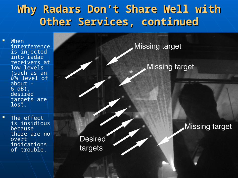
When interference is injected into radar receivers at low levels (such as an I/N level of about -6 dB), desired targets are lost.
The effect is insidious because there are no overt indications of trouble.

55
Why Radars Don’t Share Well with Other Why Radars Don’t Share Well with Other Services, continuedServices, continued
66
What is Dynamic Frequency Selection?What is Dynamic Frequency Selection?
DFS is an interference mitigation-avoidance mechanism in which a U-NII device operating in the 5 GHz bands is supposed to automatically “sense” if a radar is operating in its vicinity and vacate that frequency in a timely manner when detection occurs. DFS functions in Rlan devices are not to be user-controlled or accessible.
The Rlan devices must totally vacate the channel (no emissions) with 10 seconds of radar detection and have 260 ms of time within that to shut the network down. It must not use that channel for 30 minutes and must check a channel for 1 minute before it uses it.
77
Radar/DFS Background and HistoryRadar/DFS Background and History
In WRC-03 the bands 5250-5350 and 5470-5725 MHz bands were allocated to the mobile service on a co-primary basis with the radiodetermination service, with the provision that devices in the mobile service in these bands use DFS to protect radar systems.
In the ITU-R, Recommendation M.1652 was produced by Joint Task Group (JTG) 8A/9B internationally to facilitate development of the U-NII devices. The recommendation contains 5 GHz radar system characteristics and a description of the U-NII channel move times along with other information.
In the United States, the FCC, NTIA, and DoD along with the U-NII Industry have been working together for two years to develop certification test plans and procedures for devices that operate in the bands 5250-5350 and 5470-5725 MHz bands.
Bench tests with devices from multiple manufacturers have taken place at the ITS laboratory as well as field tests at a Southwestern test range in NM. Data were tabulated on the test results, but are not “official” NTIA or FCC reports.

88
The FCC Type Compliance TestsThe FCC Type Compliance TestsDeveloped with NTIA for 5 GHzDeveloped with NTIA for 5 GHz
U-NII Device Certification Include:U-NII Device Certification Include:
Power-on test: No Rlan emissions for 60 seconds after power-up done. Radar detection 6 seconds after power-on cycle completed. Radar detection 6 seconds before end of initial 1 minute check time. In-Service monitoring: This is the most comprehensive test as the U-NII device
must detect various synthesized radar waveforms representative of those operating the 5 GHz bands.
For in-service tests, an MPEG file is streamed from computer to computer using an access point (AP) and a Client device to load the RF channel with traffic. The AP contains built-in DFS functions.
30 minute non-occupancy test: When a channel has been identified as being used by a radar, the U-NII device must not use it for 30 minutes.
99
DFS Performance Summary TableDFS Performance Summary Table
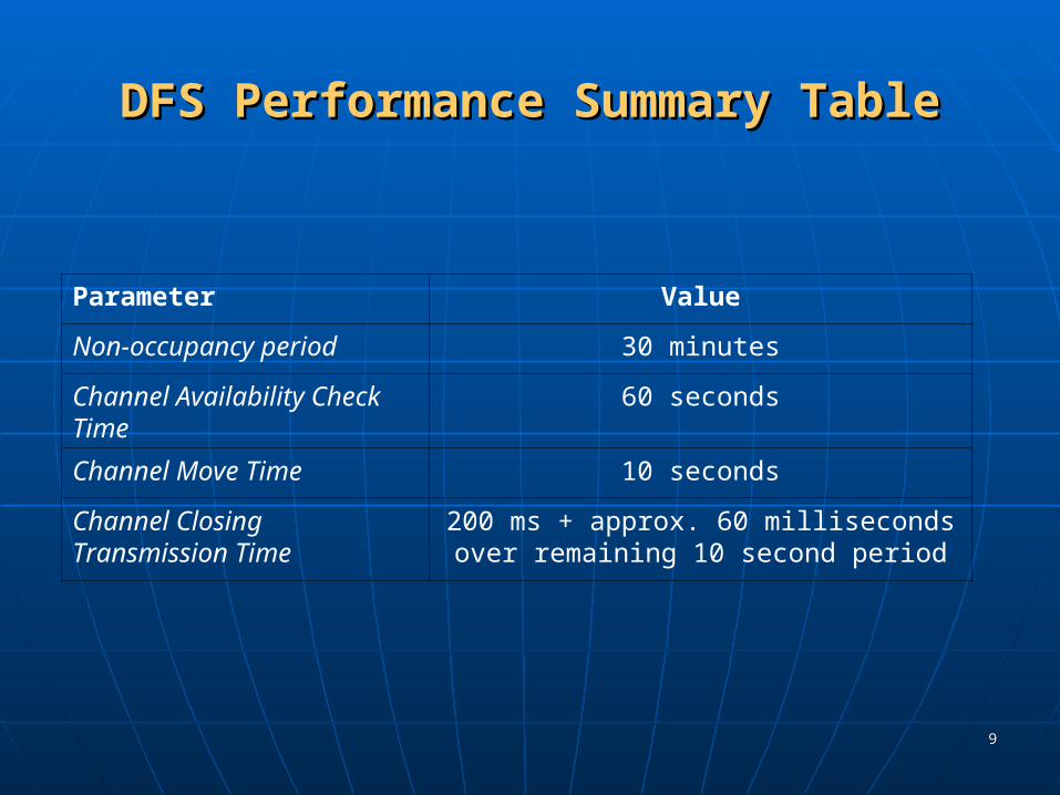
Parameter Value
Non-occupancy period 30 minutes
Channel Availability Check Time
60 seconds
Channel Move Time 10 seconds
Channel Closing Transmission Time
200 ms + approx. 60 milliseconds over remaining 10 second period

1010
Test Signals Used for the InitialTest Signals Used for the InitialRound of 5 GHz Radar/DFS Bench Tests at the ITS LaboratoryRound of 5 GHz Radar/DFS Bench Tests at the ITS Laboratory
Radar test signal Pulse repetition frequency PRF [pps]
Pulse width [µs]
Burst length L [ms] / no. of pulses (Note 1)
Burst Period [sec] (Note 2)
HoppingRate(Note 4)
Fixed Frequency Radar signal 1
700 1 26 / 18 10Na
Fixed Frequency Radar signal 2
1800 1 5 / 10 2Na
Frequency Hopping Radar 3000 1 100/300 10 1 kHz
Note 1: This represents the number of pulses seen at the unit under test (UUT) per radar scan N = [{antenna beamwidth (deg)} x {pulse repetition rate (pps)}] / [{scan rate (deg/s)}]Note 2: Burst period represents the time between successive scans of the radar beamB = 360/{scan rate (deg/s)}Note 3: Radar bandwidth is less than that of the unlicensed U-NII device.Note 4: The characteristics of this frequency hopping radar do not correspond to any specific system. It can hop across the 5250-5725 MHz band. The frequencies will be selected by using a random without replacement algorithm until all 475 frequencies have been used. After all have been used, the pattern is reset and a new random set is generated.

1111
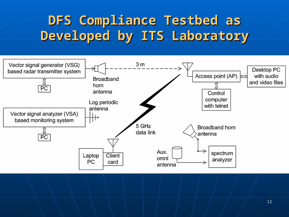
Engineers at ITS Developed a DFSEngineers at ITS Developed a DFSCompliance Testbed uses Two Main Sub-Compliance Testbed uses Two Main Sub-
systems systems Radar signal generator and synthesizer
• Produces bursts of un-modulated and chirped pulses in 5 GHz bands. Produces bursts of un-modulated and chirped pulses in 5 GHz bands.
• Variable and user selectable frequency, # of pulses, pulse width, pri, and Variable and user selectable frequency, # of pulses, pulse width, pri, and chirp bandwidth.chirp bandwidth.
• RF Power control on pulses. RF Power control on pulses.
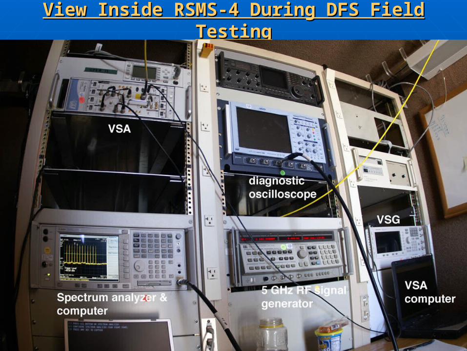
• Uses Agilent Vector Signal Generator (VSG) and other test devices.Uses Agilent Vector Signal Generator (VSG) and other test devices. Timing measurement system
• Monitors RF activity on U-NII channel. Monitors RF activity on U-NII channel.
• Uses Agilent Vector Signal Analyzer (VSA) and E4440 spectrum analyzer Uses Agilent Vector Signal Analyzer (VSA) and E4440 spectrum analyzer to have fine and coarse measurement of the RF emissions of the U-NII AP to have fine and coarse measurement of the RF emissions of the U-NII AP and client transmissions over 12 seconds. and client transmissions over 12 seconds.
• Very accurate as shown on page 9 of this presentation.Very accurate as shown on page 9 of this presentation. The two systems are synchronized so that a press of a button starts an
in-service test and collects data for 12 or 24 seconds.
1212
DFS Compliance Testbed as Developed DFS Compliance Testbed as Developed by ITS Laboratoryby ITS Laboratory
1313
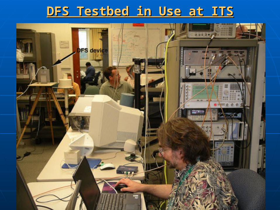
DFS Testbed in Use at ITSDFS Testbed in Use at ITS

1414
Example Data from DFS Compliance TestbedExample Data from DFS Compliance Testbed

1515
Results of Initial Round of Results of Initial Round of Radar/DFS Bench TestsRadar/DFS Bench Tests
5 GHz U-NII devices from multiple manufacturers were tested at the ITS Laboratories in Colorado, consisting of Access points (AP’s) and Client devices.
Three used 802.11 Wi-fi architectures, and one was a frame based system where the frame talk/listen ratio was user controlled.
For the in-service tests, the devices were tested with three radar waveforms:
• The radar waveform parameters are contained in the 5 GHz Report and Order (see The radar waveform parameters are contained in the 5 GHz Report and Order (see FCC docket 03-122 at http://gullfoss2.fcc.gov/prod/ecfs/comsrch_v2.cgi)FCC docket 03-122 at http://gullfoss2.fcc.gov/prod/ecfs/comsrch_v2.cgi)
• Two were fixed frequency and one was frequency agile.Two were fixed frequency and one was frequency agile.• The tests were based on MPEG video and MP3 audio files streaming from one The tests were based on MPEG video and MP3 audio files streaming from one
access point to one client using two computers, aggregate tests were not performed access point to one client using two computers, aggregate tests were not performed (AP with multiple clients).(AP with multiple clients).
• Access Point had DFS capabilities, not the Client card.Access Point had DFS capabilities, not the Client card.• Ad-hoc networks were not tested (client- to-client).Ad-hoc networks were not tested (client- to-client).
1616
Results of Initial Round of Results of Initial Round of Radar/DFS Bench Tests, continuedRadar/DFS Bench Tests, continued
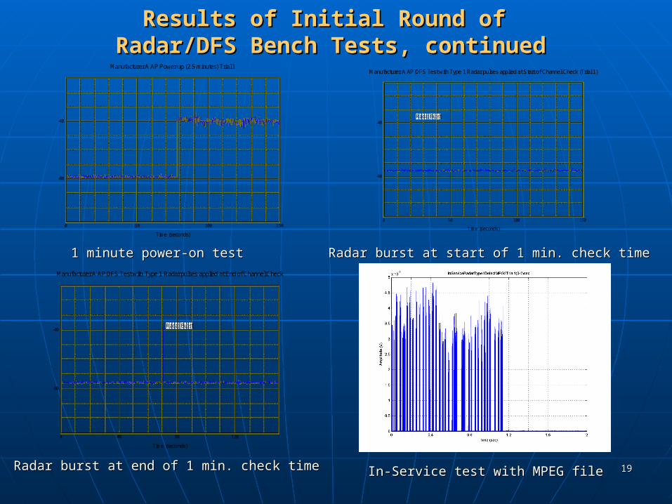
In addition to detecting radar signals at an FCC-specified power level, the U-NII devices were performing some type of pattern recognition in their radar detection algorithms by looking for specific pulse widths, pulse repetition intervals (pri), and in some cases were sensitive to the rise and fall times of the pulses themselves.
Overall, between all the manufacturers the radar detection capabilities of the devices tested were moderate at best and the radar detection was highly dependent upon the RF loading of the channel. That is, detection occurred at a higher rate when the audio file was being streamed.

1717
Results of Initial Round of Results of Initial Round of Radar/DFS Bench Tests, continuedRadar/DFS Bench Tests, continued
A key finding was that the devices were not able to detect radar pulses that were comparable in length to a typical 802.11 data packet. The devices had no way to determine if the long radar pulse was a true radar signal or a corrupted 802.11 data packet. Eliminating false detections (which cause channels to be unnecessarily vacated) was thus a challenge to the U-NII Industry in developing proper algorithms.
1818
Results of Initial Round of Results of Initial Round of Radar/DFS Bench Tests, continuedRadar/DFS Bench Tests, continued
Similar U-NII/radar DFS tests performed by other Administrations (Japan, France, Germany) drew similar results and conclusions. Their tests used radar test signals that were similar to those used in the NTIA bench tests. These administrations are watching the proceedings of the U.S. 5 GHz working group very closely and will may adopt similar rules and test procedures.
1919
Results of Initial Round of Results of Initial Round of Radar/DFS Bench Tests, continuedRadar/DFS Bench Tests, continued
-80
-40
0 50 100 150
Time (seconds)
Received Power (dBm)
Manufacturer A AP Power-up (2.5 minutes) Trial 1
-80
-40
0 50 100 150
Radar Burst
Time (seconds)
Received Power (dBm)
Manufacturer A AP DFS Test with Type 1 Radar pulses applied at Start of Channel Check (Trial 1)
-80
-40
0 40 80 120
Radar Burst
Time (seconds)
Received Power (dBm)
Manufacturer A AP DFS Test with Type 1 Radar pulses applied at End of Channel Check
Radar burst at start of 1 min. check timeRadar burst at start of 1 min. check time
Radar burst at end of 1 min. check timeRadar burst at end of 1 min. check time
1 minute power-on test1 minute power-on test
In-Service test with MPEG fileIn-Service test with MPEG file
2020
Results of Initial Round of Results of Initial Round of Radar/DFS Bench Tests, continuedRadar/DFS Bench Tests, continued
It was also apparent that radars utilizing longer pulse widths needed to be protected as some are vital to the nation’s defense and must be detected in a timely manner.
Their characteristics are contained in ITU-R M.1652, which was developed in the US with participation by DoD and the Rlan industry.
2121
How We Moved Forward to AlleviateHow We Moved Forward to Alleviate DoD Concerns for Protecting Radar Systems DoD Concerns for Protecting Radar Systems
and Accommodate U-NII Industry Desire to and Accommodate U-NII Industry Desire to Market & Sell 5-GHz devices Market & Sell 5-GHz devices
Developed a set of radar signal parameters, including those with long pulses, that are representative of radar systems operating in the 5 GHz band for FCC type acceptance compliance tests.
Guarded against specific radar signal pattern recognition by having a wide variation in the characteristics, i.e., pulse width, pri, number of pulses per burst, and chirp bandwidth.
Performed additional bench tests at the ITS laboratories with the new set of radar signal parameters and updated 5 GHz devices provided by the U-NII Industry.
Using the same U-NII devices that were tested in the laboratory (without any software or hardware modifications), tests were performed with an operational radar at a test range in New Mexico.
FCC rules are written to prevent any end user from accessing the U-NII device algorithms and extracting ANY information about the radar signal that was detected.
Used the results of the bench and field tests to validate the radar signal test parameters, the test procedures, and true proof of concept.
Publish a final set of FCC type acceptance rules and test procedures for companies that want to market and sell these devices.

2222
Parameters for the New Parameters for the New Set of Radar Signal Characteristics for FCC Set of Radar Signal Characteristics for FCC
Compliance TestingCompliance TestingTable 1: Fixed System Radars (no modulation)
Long Pulse
Radar Set
Pulse Width(µsec)
PRI(µsec)
ChirpBandwidt
h(MHz)
# of Pulses
Per burst
Minimum probability of detection
MinimumTrials
1[1] 50-100 1000-2000
5-20 1-3 80% 30
Table 2: Long Pulse Radar signal with Chirp
Fixed Radar Set
Pulse Width(µsec)
PRI(µsec)
# o PulsesPer burst
MinimumProbability of
Detection
MinimumTrials
1 - fixed 1 1428 18 60% 30
2 - variable 1-5 150-230 23-29 60% 30
3 - variable 6-10 200-500 16-18 60% 30
4 - variable 11-20 200-500 12-16 50% 30
Aggregate of 80 percentAggregate of 80 percent

2323
Parameters for the Parameters for the New Set of Radar Signal Characteristics New Set of Radar Signal Characteristics for FCC Compliance Testing, continuedfor FCC Compliance Testing, continued
Table 3: Frequency Hopper (no modulation)
Radar Waveform
Pulse Width(µsec)
PRI(µsec)
BurstLength
(ms)
Pulses per Hop
HoppingRate (kHz)
Minimum Percentage of
Successful Detection
Minimum Trials
6 - Fixed 1 333 300 9 .333 70% 30
2424
Need for DFS Field TestingNeed for DFS Field Testing
- Additional information was required by all - Additional information was required by all agencies concerning the ability of prototype agencies concerning the ability of prototype devices to ‘see’ signals from operational radars.devices to ‘see’ signals from operational radars.
- Design and feasibility of lab testing was - Design and feasibility of lab testing was demonstrated; information was sent to the FCC demonstrated; information was sent to the FCC and other agencies.and other agencies.
- Field tests of such devices near operational - Field tests of such devices near operational radars were therefore planned.radars were therefore planned.
2525
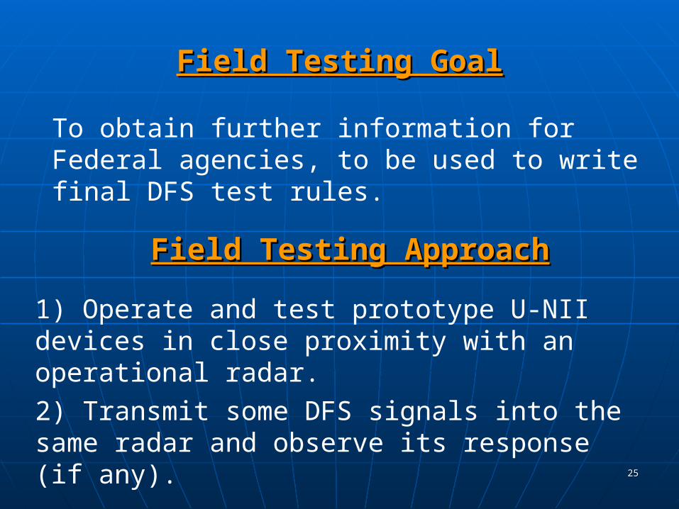
Field Testing GoalField Testing Goal
To obtain further information for Federal agencies, to be used to write final DFS test rules.
Field Testing ApproachField Testing Approach
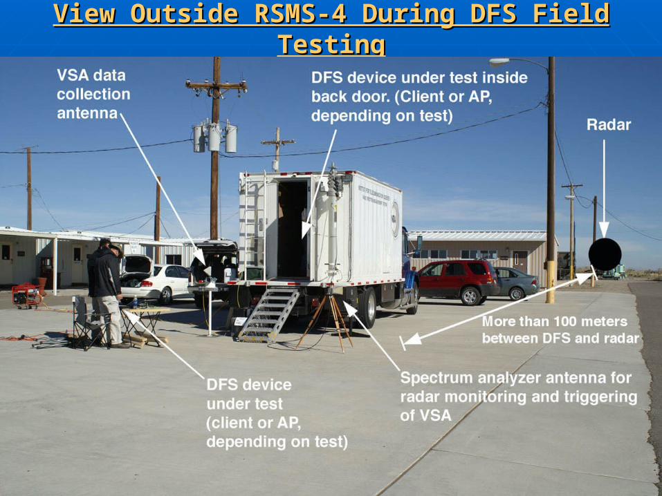
1) Operate and test prototype U-NII devices in close proximity with an operational radar.
2) Transmit some DFS signals into the same radar and observe its response (if any).
2626
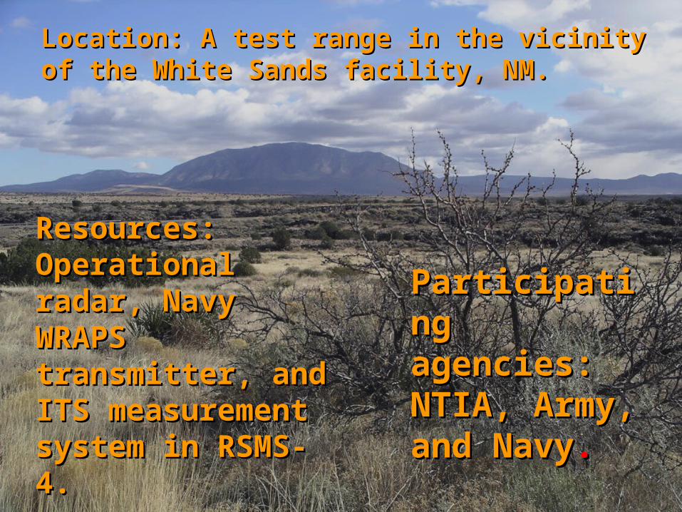
Location: A test range in the vicinity of the Location: A test range in the vicinity of the White Sands facility, NM.White Sands facility, NM.
Participating Participating agencies: agencies: NTIA, Army, NTIA, Army, and Navyand Navy..
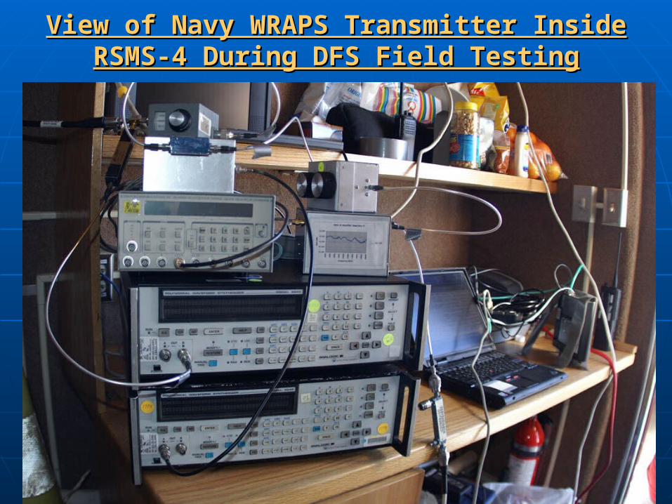
Resources: Resources: Operational radar, Operational radar, Navy WRAPS Navy WRAPS transmitter, and ITS transmitter, and ITS measurementmeasurement system in RSMS-4.system in RSMS-4.
2727
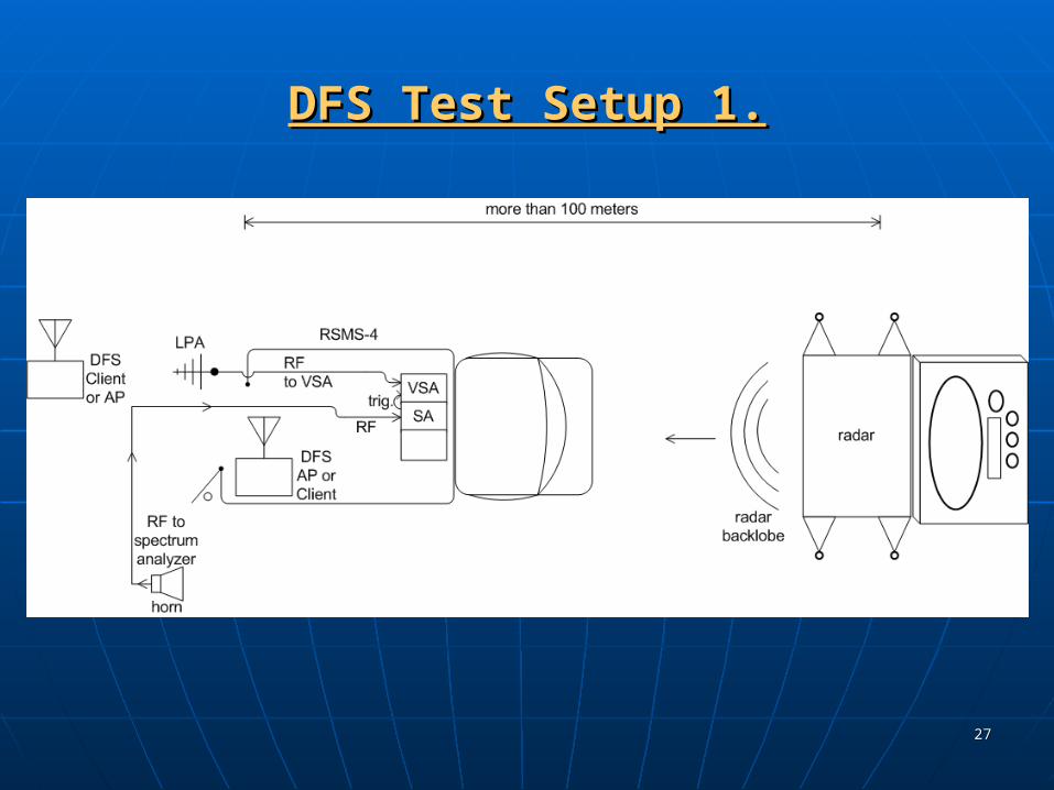
DFS Test Setup 1.DFS Test Setup 1.
2828
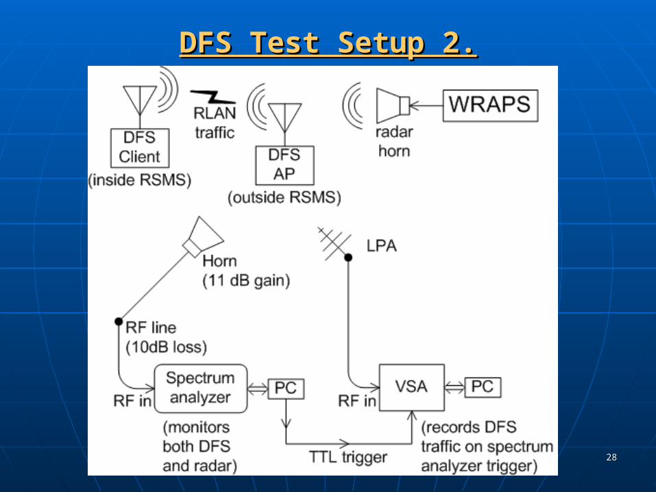
DFS Test Setup 2.DFS Test Setup 2.

2929
Procedures for DFS Field TestingProcedures for DFS Field Testing
1) Select an operational mode for the radar.
2) Start traffic between the U-NII AP and client devices.
3) Call the radar operator (via handie talkie) and request a burst of radar pulses in that mode.
4) Observe whether the U-NII device sensed the burst, and record the DFS response with a VSA & spectrum analyzer.
5) Repeat steps 2-4 at between 10-30 times.
6) Repeat steps 1-5 for a large number of radar modes.
3030
View Inside RSMS-4 During DFS Field TestingView Inside RSMS-4 During DFS Field Testing
3131
View of Navy WRAPS Transmitter InsideView of Navy WRAPS Transmitter InsideRSMS-4 During DFS Field TestingRSMS-4 During DFS Field Testing
3232
View Outside RSMS-4 During DFS Field TestingView Outside RSMS-4 During DFS Field Testing
3333
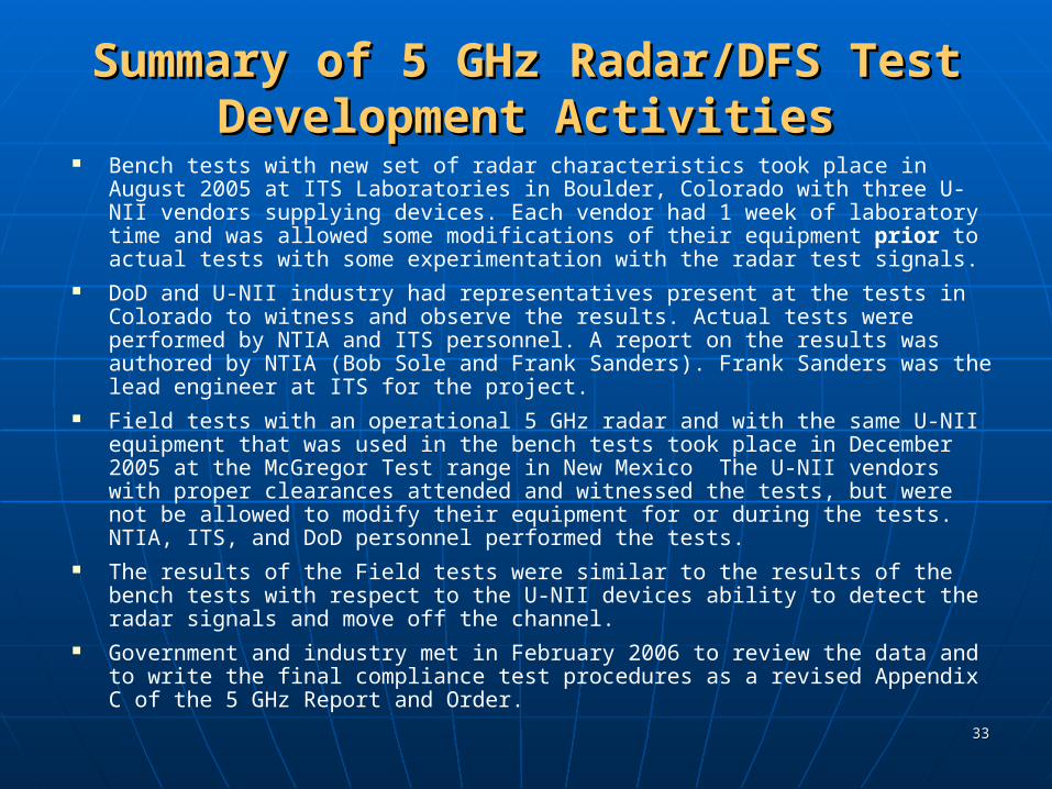
Summary of 5 GHz Radar/DFS Test Summary of 5 GHz Radar/DFS Test Development ActivitiesDevelopment Activities
Bench tests with new set of radar characteristics took place in August 2005 at ITS Laboratories in Boulder, Colorado with three U-NII vendors supplying devices. Each vendor had 1 week of laboratory time and was allowed some modifications of their equipment prior to actual tests with some experimentation with the radar test signals.
DoD and U-NII industry had representatives present at the tests in Colorado to witness and observe the results. Actual tests were performed by NTIA and ITS personnel. A report on the results was authored by NTIA (Bob Sole and Frank Sanders). Frank Sanders was the lead engineer at ITS for the project.
Field tests with an operational 5 GHz radar and with the same U-NII equipment that was used in the bench tests took place in December 2005 at the McGregor Test range in New Mexico The U-NII vendors with proper clearances attended and witnessed the tests, but were not be allowed to modify their equipment for or during the tests. NTIA, ITS, and DoD personnel performed the tests.
The results of the Field tests were similar to the results of the bench tests with respect to the U-NII devices ability to detect the radar signals and move off the channel.
Government and industry met in February 2006 to review the data and to write the final compliance test procedures as a revised Appendix C of the 5 GHz Report and Order.