Embed Size (px)
Citation preview

1 CONCEPTUAL PLAN
1.1 PROPOSAL:
Expansion of facility “Divya Sree Point IT Park” in Sholinganallur village in an
area of 15060 m2 . The built up area after expansion is 75282.21 m2
1.2 PROMOTERS:
The project is promoted by “Divyasree Infrastructure Developers Pvt Ltd ”. The
registered address is - Door No 07, Rajiv Gandhi Salai, Old Mahabalipuram Road,
Sholinganallur, Chennai -600119
1.3 PROJECT:
The proposed project is Expansion of Commercial building . The project details are
given below:
Item Details
Project Name “Divya Sree Point IT Park”
Location SNO 449/1A, 450/1,450/2A and 450/2B
Type of project Commercial development
Total Plot Area 15060 sq.m
Built up area (Existing) 53129 m2
Built up area (After Expansion 75282.21 m2
Ground Coverage 5796.75 m2
Surface Parking, Roads & pavements
4522.4 m2
Green Belt 2148 m2
Building Height 53 m
Power requirement Power requirment Existing Proposed
Power 7114 kVA with 3×2500 kVA transformer
7114 kVA with 3×2500 kVA transformer
Source of power TANGEDCO
Power backup DG sets of 6 x 1500 kVA
1.4 LAND & LOCATION:
Proposed expansion will be located within an area of 15060 m2. The location map
and the satellite image is enclosed as Annexure-9. The Approved layout plan is
enclosed as Annexure-10.
1.5 SERVICES & UTILITIES:
Construction Materials: The major materials required in the construction are steel,
cement, bricks, metal, flooring tiles/stones, wood, sanitary and hardware items,
electrical fittings, water, etc. All the items to be used in the proposed project will be
of good quality as much as procuring directly from the dealers or manufacturers
will use possible ISI brand items. Local items sand, metal, bricks, etc will be
procured through standard suppliers in the market. The required construction
materials are given below
Steel 648263 kg Cement 264167 50 kg bags
Sand 26846.7 cu.m Stone aggregates (10mm) 4130 cum Stone aggregates (20mm) 7572 cum
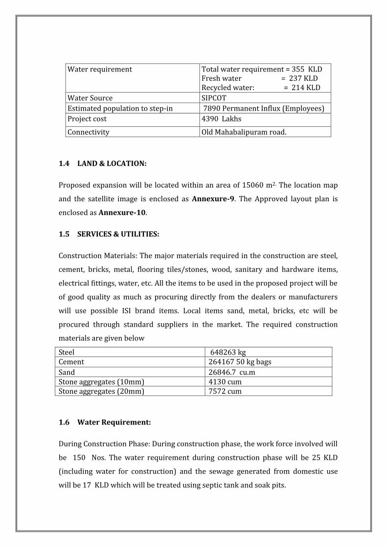
1.6 Water Requirement:
During Construction Phase: During construction phase, the work force involved will
be 150 Nos. The water requirement during construction phase will be 25 KLD
(including water for construction) and the sewage generated from domestic use
will be 17 KLD which will be treated using septic tank and soak pits.
Water requirement Total water requirement = 355 KLD Fresh water = 237 KLD Recycled water: = 214 KLD
Water Source SIPCOT
Estimated population to step-in 7890 Permanent Influx (Employees)
Project cost 4390 Lakhs
Connectivity Old Mahabalipuram road.

During Operation Phase: The daily requirement of water will be 355 KLD. Fresh
water demand is 237 KLD & recycle water is 214 KLD. After treatment of
wastewater, treated water will be reused for flushing and green belt. The source of
water is met from SIPCOT . The water Balance is enclosed as Annexure -5.
Sewage Treatment Plant:
During operation, 292 KLD of wastewater will be generated which will be treated in
the sewage treatment plant of 340 KLD and the treated sewage will be recycled for
flushing , HVAC makeup and gardening. The design parameters, process
description and schematic flow diagram of the STP is given in Annexure -14.
The sewage collection system, STP location, Schematic representation of Dual
plumbing system is enclosed in Annexure -15.
Sewage Quantity, Treatment, Reuse & Disposal
Quantity of sewage 292KLD
STP Capacity 340 KLD
Collection of sewage &
effluent
Waste water generated during the operation phase will be
collected through sewerage system (pipe drain) for treatment
in 340 KLD STP.
Treatment of sewage Sewage will be treated up to the tertiary level in a Sewage
Treatment Plant based on Activated sludge process. The
secondary treated sewage will be treated in UF plant.
Reuse / recycle of
treated sewage
Out of 292 KLD of treated water, 118 KLD will be recycled for
toilet flushing 6 KLD for gardening, 88KLD for HVAC make
up and excess 80 KLD will be disposed to CMWSSB sewer line
1.7 Rain water Harvesting & Storm Water Management:
Rain water from roof tops will be drained through rain water vertical down take
pipes. These vertical down take pipes shall be located at suitable locations inside
the shafts or periphery of the building. The terrace will be sloped. The down take
pipes will be connected to the rainwater storage tank & it will be used after suitable
treatment. Rainwater harvesting calculation and the plan showing the location of
RWH system, storm water drainage network and rainwater harvesting pits is given
in Annexure 13.

POWER: The maximum demand has been estimated as 7114 kVA with 3×2500
kVA transformer for existing and proposed expansion facility. The local
electricity board TANGEDCO will supply the required power. For back-up support,
DG sets of 6 x 1500 kVA DG sets exist.
Step in Population: The total population 7890 (Employees) has been estimated
as temporary influx.
1.8 Solid Waste Management
a. Construction phase: Solid wastes of construction phase will constitute
excess excavated earth and construction debris with bits and pieces of steel,
air-conditioning insulation material, packaging material and wood used for
shuttering purposes etc.
No construction material or wastes e.g. excavated soil, debris etc. will be
dumped outside the project area.
Construction waste and debris will in general be used for filling of land
within the premises.
Unusable steel bits and pieces, piping, concrete reinforcement will also be
collected at site and sold to recyclers
A significant portion of wood scrap can be reused on site.
Recyclable wastes such as Cement bags, waste paper and cardboard packing
material, glass fibre insulation etc shall be sold to recyclers.
Construction sites are sources of many toxic substances such as paints,
solvents, wood preservatives etc. Wastes generated from these sources
during construction phase shall be stored in sealed containers, labelled and
disposed of as required by the Hazardous Wastes Management and Handling
act Amendment Rules (MoEF 2003).
Excavated earth quantity will be around 96142 m3 . Excess Excavated earth
will be used for Backfilling, Soft landscaping, Road formation and filling low
lying areas. Top soil will be stacked separately and used for green belt
development.
The construction debris will be segregated viz., steel, metal, plastics, papers
etc. Maximum effort will be taken to recycle the wastes and other wastes will

be sold to scrap dealers. There will not be any health hazard due to this
debris
b. Operation Phase:
About 5050 kg/ day of solid wastes are likely to be generated due to the
proposed project.
Waste Quantity (kg/day) Treatment method
Organic 2236 Treated in Bio Gas plant and used for Electricity
STP Sludge 80 Composted and used as manure
Inorganic 2734 Sold to authorised recyclers
Hazardous Wastes:
Name of the waste Quantity Mode of disposal Area of land
earmarked for storage
and disposal
Used Oil 5550 KL/A
Disposed to TNPCB
Approved Vendor
Waste storage area -
75sqm
Waste / residue containing oil 1.0 T/A
E-Waste 6.1 T/A
The details of solid wastes collection recycle and disposals are given in the
Table below.
Solid Wastes Collection, Recycle & Disposal
Construction debris The approximate quantity will be 7665.58 cum. Maximum
care will be taken to reuse the same. Scrapes will be sold
to authorized vendors
Quantity of solid wastes
during operational Phase
5050 Kg / day (Organic waste – 2236 Kg/day, Inorganic
Waste –2734 kg/day; Sludge – 80 Kg/day)
Nature of solid wastes Organic waste: Waste vegetables, foods, leaves, STP
Sludge etc.
Inorganic waste: Plastics, polythene bags, glass etc.
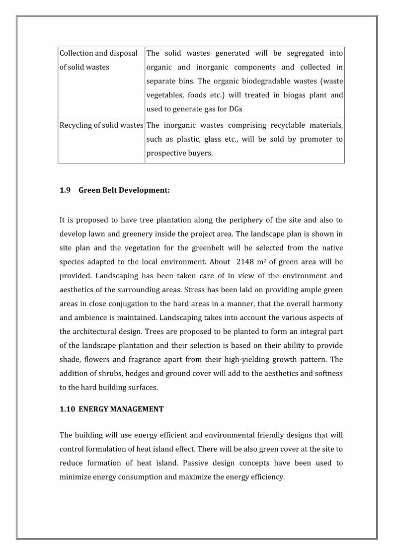
Collection and disposal
of solid wastes
The solid wastes generated will be segregated into
organic and inorganic components and collected in
separate bins. The organic biodegradable wastes (waste
vegetables, foods etc.) will treated in biogas plant and
used to generate gas for DGs
Recycling of solid wastes The inorganic wastes comprising recyclable materials,
such as plastic, glass etc., will be sold by promoter to
prospective buyers.
1.9 Green Belt Development:
It is proposed to have tree plantation along the periphery of the site and also to
develop lawn and greenery inside the project area. The landscape plan is shown in
site plan and the vegetation for the greenbelt will be selected from the native
species adapted to the local environment. About 2148 m2 of green area will be
provided. Landscaping has been taken care of in view of the environment and
aesthetics of the surrounding areas. Stress has been laid on providing ample green
areas in close conjugation to the hard areas in a manner, that the overall harmony
and ambience is maintained. Landscaping takes into account the various aspects of
the architectural design. Trees are proposed to be planted to form an integral part
of the landscape plantation and their selection is based on their ability to provide
shade, flowers and fragrance apart from their high-yielding growth pattern. The
addition of shrubs, hedges and ground cover will add to the aesthetics and softness
to the hard building surfaces.
1.10 ENERGY MANAGEMENT
The building will use energy efficient and environmental friendly designs that will
control formulation of heat island effect. There will be also green cover at the site to
reduce formation of heat island. Passive design concepts have been used to
minimize energy consumption and maximize the energy efficiency.

a. Solar Architectural Features
The entire layout has been designed to take advantage of the local climatic
conditions, the sun path and wind direction.
Large windows have been proposed at regular intervals to invite daylight.
i. Characteristics of Glass, Roof, Wall
Sr.
No.
Name of
material
Thickness in mm U value in
w/m2°C
1 Glass Double glazing with 6mm
Clear glass
3.28
2 Opaque wall 200 1.71
3 Roof Assembly 100mm RCC slab with average
100mm brick bat coba
underdeck/overdeck 75mm
thick polystyrene
0.301
b. Solar Powered street lights
For the Solar Power is proposed to be utilized for street lighting in common area.
c. Energy Efficient Systems
i. A water cooled air-conditioning system is used instead of air-cooled system.
ii. Water cooled screw chillers are used with environmental friendly
Refrigerant R – 34a.
iii. Variable speed secondary pumping system is proposed for chilled water to
derive energy savings during part loads.
iv. Cooling towers will have variable speed drives to derive energy savings during
part load and low wet bulb periods.
v. All Public area air handling units will be provided with variable speed drives.
vi. Entire HVAC system will be optimized for energy efficiency through a Building

vii. Management System.
viii. Electric motor drives for all fans, AHU’s and pumps will be high efficiency
motors to IS: 12615 – 2004 and also will comply with ECBC norms
d. Energy conservation in plumbing System
a) Variable speed pumping system will be adopted for water distribution.
b) All W.C’s will have 3 – 6 litres dual- flush cistern.
c) All public wash basins & urinals will have proximity sensors.
d) Heat recovered from the de super heaters from the chillers will also be used to
pre- heat the cold water.
e. Conservation in electrical system
e) Energy efficient CFL/T5 lamps for common areas. Use of low loss electronic
ballasts.
f) Multiple circuits for lighting to switch off unwanted lights.
g) Use of low loss capacitors, APFC relays.
h) Group control for elevators
i) Proper selection & sizing of cables considering de rating factors so as to
minimize losses.
j) High efficiency motors conforming to IS: 2615 – 2004.
1.11 Parking And Traffic Management
a. Proposed Parking Facilities: It is proposed to provide the following
parking facilities
S.
No
Type of
vehicles
Surface
parking
Stilt
parking
Stilt
first
floor
1st
Basement
parking
2nd
Basement
parking
Area in
Sq.m
1. Two
wheelers
47 165 57 241 251 684.9
2. Cars 90 68 99 90 106 6795
Total 137 233 156 341 347 7479.9

b. Traffic Management Plan: The project will have access to Old
Mahabalipuram road. The internal roads of 6 m, pedestrian pathways, entry/
exits and traffic circulation plan have been shown in the traffic circulation
plan enclosed. In the circulation plan of the project, there will be proper
entry and exit points for systematic control of the vehicular movement
within the site. The parking and traffic circulation plan, Entry, Exit is
enclosed in Annexure-16
1.12 FIRE FIGHTING SYSTEMS
Adequate fire protection facilities will be installed including fire detectors, fire
alarm and fire fighting system to guard the building against fires. All fire protection
facilities are designed as per the latest National Building Code. NOC from fire
department is enclosed in Annexure -18
1.13 MITIGATION MEASURES FOR AIR POLLUTION
a. Construction Stage: During the construction stage there are chances of fugitive
dust generation due to (i) excavation, (ii) movement heavy construction vehicles
along the haul roads and (iii) storage and handling of construction materials.
However, the generation of such dusts is most likely limited within the project
boundary and negligible quantity is expected to the surrounding environment. To
minimize such impact following measures shall be under taken:
i. Site clearance
The working area for the uprooting of shrubs or vegetation or for the removal of
boulders or temporary or permanent structures shall be sprayed with water or a
dust suppression chemical immediately before, during and immediately after the
operation so as to maintain the entire surface wet.
ii. Haul Road:
Every main haul road (i.e. any course inside a construction site having a vehicle
passing rate of higher than 4 in any 30 minutes) shall be paved with concrete,
bituminous materials, metal plates, and kept clear of dusty materials; or sprayed
with water or a dust suppression chemical so as to maintain the entire road surface
wet.

Regular water spraying on haulage roads during transportation of construction
materials by water sprinklers
Transfer points for transporting construction materials shall be provided with
appropriate hoods/chutes to prevent dust emissions;
Dumping of construction materials should be from an optimum height (preferably
not too high) so as to reduce the dust blow
iii. Use of vehicle
Immediately before leaving a construction site, every vehicle shall be washed to
remove any dusty materials from its body and wheels.
Where a vehicle leaving a construction site is carrying a load of dusty materials, the
load shall be covered entirely by clean impervious sheeting to ensure that the dusty
materials do not leak from the vehicle.
iv. Stock Piles:
All loose material either stocked or transported shall be provided with suitable
covering such as tarpaulin, etc.
Water sprinkling shall be done at the location where dust generation is anticipated;
Over Burden (OB) waste dumps shall be sprayed with water as they are major
sources of air borne particulate matter/dust; and,
OB waste dumps shall be reclaimed / afforested to bind the loose soil and to
prevent soil erosion.
v. Building construction
Where a scaffolding is erected around the perimeter of a building under
construction, effective dust screens, sheeting or netting shall be provided to enclose
the scaffolding from the ground floor level of the building
Any skip hoist for material transport should be totally enclosed by impervious
sheeting
b. Operation Stage :
Table below gives the overview of the Air Pollution Control measures adopted
during the project operation stage

1.1 Air Pollution Control Measures
S. N. Air
pollutant
Source Control Measures
1 SO2, NOx DG sets Adequate stack height of 53 m for the 6 stacks as per
CPCB norms.
Adequate stack is provided for the release of pollutants from DG and from process
equipment. Both during construction & operation phase no significant impact on
visibility and any other meteorological parameters were observed
S.No Source of Emission APC measures provided Stack height (m)
1. DG set -1500 KVA-6 Nos
Acoustic enclosure with stack 53 (6 Nos)
2. Vehicular emissions Dust, SO2, NOx, CO,
HC
Roads will be maintained properly to reduce dust. All vehicle owners will be informed to follow the emission standards fixed by the government authorities to keep the air pollutants under control. Pollution under Control checkup camps will be arranged for vehicles.
N.A
i. Measures for Controlling Vehicular Emission: To control the
emissions from the movement of vehicular traffic in the proposed
project, following measures shall be adopted:
Proper maintenance of the internal paved areas inside the
boundary.
Adequate greenbelt will be developed and maintained as described
in the subsequent portions.
Informatory sign shall be provided to encourage vehicle owners to
maintain their vehicle and follow the emission standards fixed by
Government Authorities.
ii. Control of Sulphur Dioxide Emission: To minimize the effect of
sulphur dioxide emissions on ambient air quality, a stack is installed
for the exhaust of the flue gases at a safe height complying with the
standards laid down by MoEF. The main source of SO2 emissions
from the proposed project is the DG set operations. It would be
ensured that all stacks of DG sets would be designed as per the stack
height norms of MoEF. Diesel used for the DG sets will comply with
the MOEF specifications.
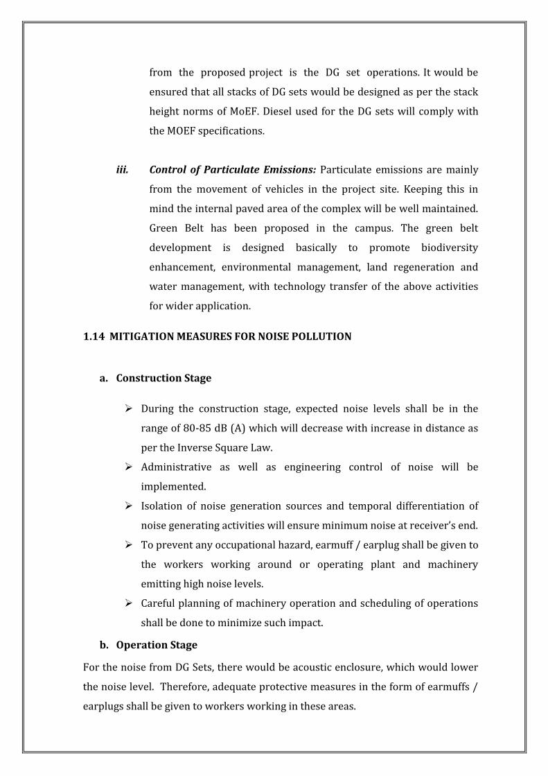
iii. Control of Particulate Emissions: Particulate emissions are mainly
from the movement of vehicles in the project site. Keeping this in
mind the internal paved area of the complex will be well maintained.
Green Belt has been proposed in the campus. The green belt
development is designed basically to promote biodiversity
enhancement, environmental management, land regeneration and
water management, with technology transfer of the above activities
for wider application.
1.14 MITIGATION MEASURES FOR NOISE POLLUTION
a. Construction Stage
During the construction stage, expected noise levels shall be in the
range of 80-85 dB (A) which will decrease with increase in distance as
per the Inverse Square Law.
Administrative as well as engineering control of noise will be
implemented.
Isolation of noise generation sources and temporal differentiation of
noise generating activities will ensure minimum noise at receiver’s end.
To prevent any occupational hazard, earmuff / earplug shall be given to
the workers working around or operating plant and machinery
emitting high noise levels.
Careful planning of machinery operation and scheduling of operations
shall be done to minimize such impact.
b. Operation Stage
For the noise from DG Sets, there would be acoustic enclosure, which would lower
the noise level. Therefore, adequate protective measures in the form of earmuffs /
earplugs shall be given to workers working in these areas.

An adequate green belt cover shall be provided and the species will be selected
based upon their Air-Pollution Tolerance Index (APTI), Noise abatement capacity
and local availability and landscape requirements. Thus through the greenbelt
there shall be significant attenuation of noise generation.
1.15 ENVIRONMENTAL MONITORING PLAN
To check the effectiveness of mitigation measures as proposed, a detail
environmental monitoring plan shall be implemented both during the construction
and operation stage of the project. There shall be a project implementation unit
(PIU) and it will be the responsibility of PIU to implement such monitoring
programme. Such monitoring activities will help the PIU to maintain the quality of
environment through adequate checking and control of mitigation measures and
environmental infrastructures. There shall be monitoring programme both for the
construction and operation stages of the project. Environmental Management plan
is enclosed in Annexure 19.
1.16 CONCLUSION:
There is minimum negative impact on Air, Noise and Water Environment.
Treated Waste Water will be reused for gardening and flushing.
Rain Water harvesting system is proposed.
Organic waste converter for solid waste management is proposed.
There will be positive Impact on Social conditions in and around the site.
The Project will not result in any adverse impact to the Environment.
The marginal impact of setting up the Development in the proposed location will be
fully mitigated by the Environment Management Plans. (EMP)


![Put x = H.C.F. (3, 2 × 6) = H.C.F. (3, 6) [True] · log x = 40 × 0.301 log x = 12.04 log 13 ≅ 12.04 ... = 7 ½ days S31.Ans() Sol. ... (x² + 4x + 4) = x](https://img.pdfslide.us/doc/110x75/5bf9069409d3f2ac7c8cbae5/put-x-hcf-3-2-6-hcf-3-6-true-log-x-40-0301-log-x.jpg)