Embed Size (px)
Citation preview
1
CO2 cooling activities at NIKHEF
Bart VerlaatNational Institute for Particle Physics
(NIKHEF)Amsterdam, The Netherlands
Development of the Velo Thermal Control
System (VTCS)
CERN, 13 March 2008
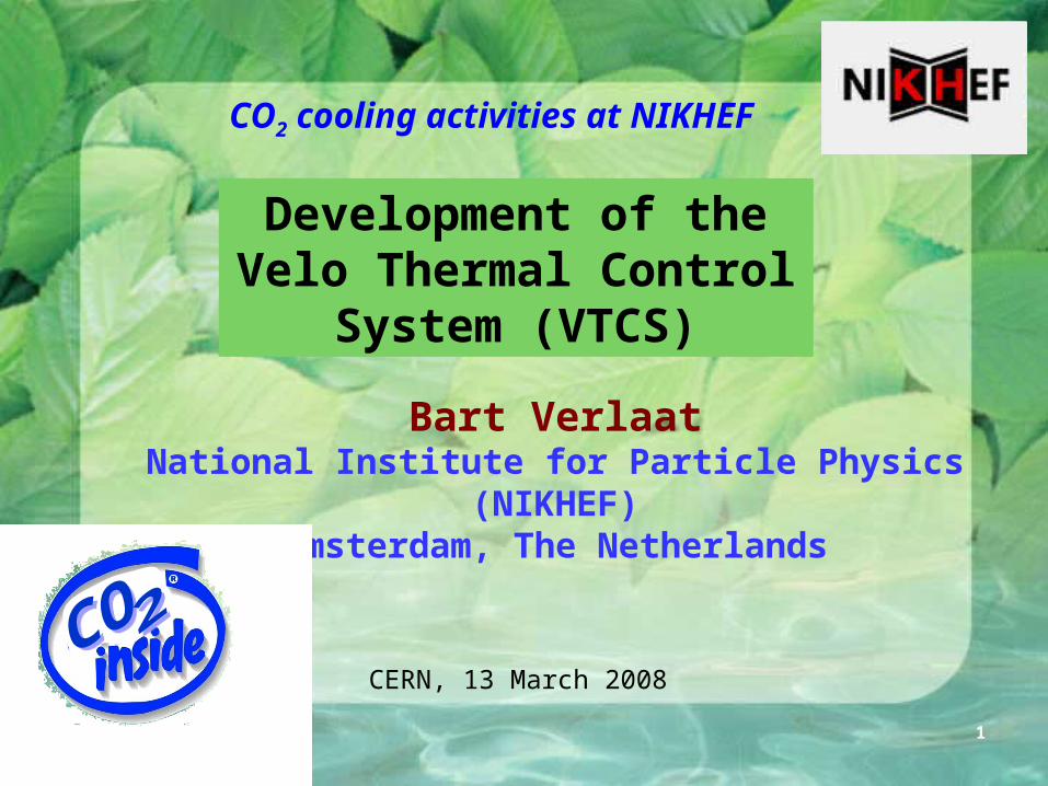
(Silicon) Particle Detectors and Cooling
• (Silicon) Particle detectors have specific needs for thermal control:
– Many distributed heat sources over large volumes.
• Serial evaporators– Low temperature gradients between these
sources.• Low pressure drop, constant heat transfer coefficients
– Permanent cooling (<0ºC, With or without heat load)
• Irradiated detectors will get damaged when becoming warm– Low mass inside detectors
• Light weight evaporators, low volume, => mini-channels– Low structural impact
• Small diameter tubing, wiggly structure– Radiation resistant cooling fluid• The above mentioned properties have led to the development of CO2 loops at Nikhef, because CO2 is:
– Radiation hard– Has excellent thermodynamic
properties for micro-channels. • Low dT/dP• Low mass • Low liquid/vapor density ratio• Low viscosity• High latent heat• High heat transfer coefficient
Alpha Magnetic Spectrometer
Silicon Tracker
Particle detection surface(Low material, homogeneous
and stabile temperature)
Multiple electronic stations(All need cooling)
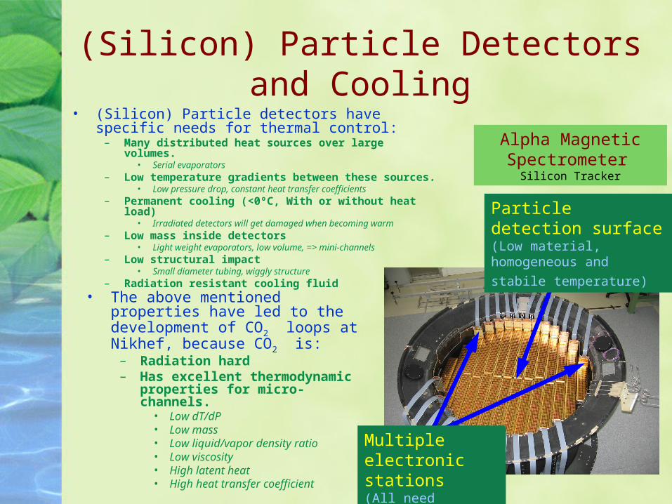
-40.0
-20.0
0.0
20.0
40.0
60.0
80.0
0.0 1.0 2.0 3.0 4.0 5.0 6.0 7.0 8.0 9.0 10.0
Tube
tem
pera
ture
Flui
d te
mpe
ratu
reSat
ura
ted
liq
uid
Par
tial d
ry-o
ut
Sat
ura
ted
vap
or
Sub cooled liquid 2-phase liquid / vapor Super heated vapor
Dry-out zoneTarget flow condition
Tem
per
atur
e (°
C )
Tube length (m)
Typical temperature distribution of a heated tube
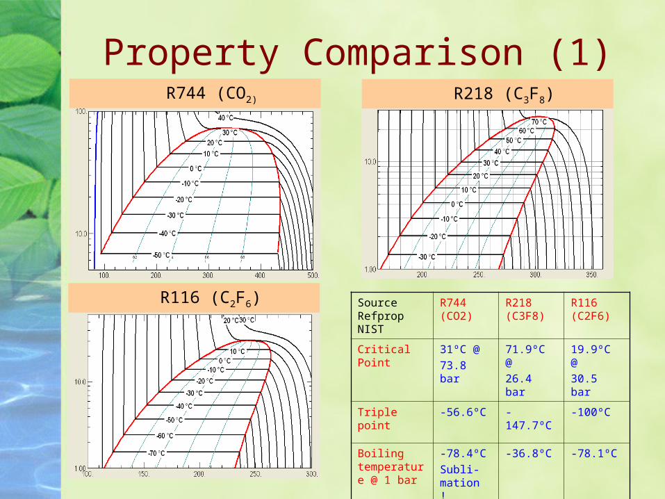
Property Comparison (1)R744 (CO2)
R116 (C2F6)
R218 (C3F8)
Source Refprop NIST
R744 (CO2)
R218 (C3F8)
R116 (C2F6)
Critical Point
31ºC @ 73.8 bar
71.9ºC @26.4 bar
19.9ºC @30.5 bar
Triple point -56.6ºC -147.7ºC -100ºC
Boiling temperature @ 1 bar
-78.4ºC Subli-mation !
-36.8ºC -78.1ºC
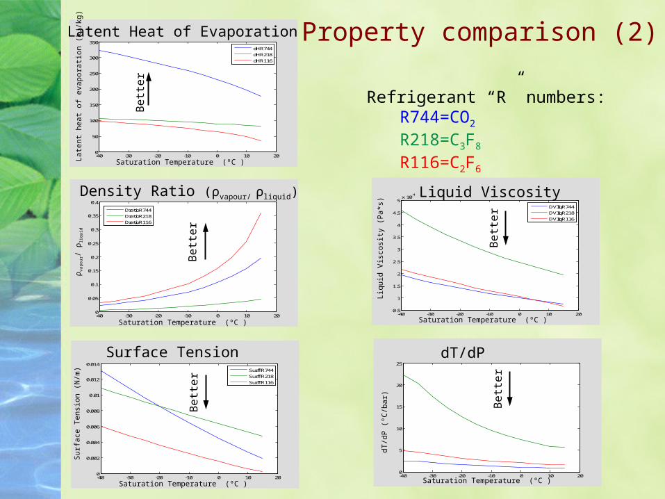
Property comparison (2)
Refrigerant “R” numbers:R744=CO2
R218=C3F8
R116=C2F6
-40 -30 -20 -10 0 10 200
0.05
0.1
0.15
0.2
0.25
0.3
0.35
0.4
DratioR744
DratioR218
DratioR116
Density Ratio (ρvapour/ ρliquid)
Saturation Temperature (ºC )
ρva
po
ur/
ρliq
uid
Be
tte
r
-40 -30 -20 -10 0 10 200
0.002
0.004
0.006
0.008
0.01
0.012
0.014
SurfTR744
SurfTR218
SurfTR116
Surface Tension
Saturation Temperature (ºC )
Sur
face
Ten
sion
(N
/m)
Be
tte
r
-40 -30 -20 -10 0 10 200.5
1
1.5
2
2.5
3
3.5
4
4.5
5x 10
-4
DVliqR744
DVliqR218
DVliqR116
Liquid Viscosity
Saturation Temperature (ºC )
Liqu
id V
isco
sity
(P
a*s)
Be
tte
r
-40 -30 -20 -10 0 10 200
50
100
150
200
250
300
350
dHR744
dHR218
dHR116
Latent Heat of Evaporation
Saturation Temperature (ºC )
Late
nt h
eat
of e
vapo
ratio
n (k
J/kg
)
Be
tte
r
-40 -30 -20 -10 0 10 200
5
10
15
20
25
dT/dP
Saturation Temperature (ºC )
dT/d
P (
ºC/b
ar) Be
tte
r
Refrigerant “R” numbers:R744=CO2
R218=C3F8
R116=C2F6
-40 -35 -30 -25 -20 -15 -10 -5 0-2
-1.5
-1
-0.5
0
Saturation Temperature (̀ C)
Pres
ure
drop
(bar
)
dPresR744
dPresR218dPresR116
-40 -35 -30 -25 -20 -15 -10 -5 0-30
-25
-20
-15
-10
-5
0
Saturation Temperature (̀ C)
Tem
pera
tre d
rop
(̀C)
dTempR744
dTempR218
dTempR116
4mm ID Tube
-40 -35 -30 -25 -20 -15 -10 -5 0-20
-15
-10
-5
0
Saturation Temperature (̀ C)
Pre
sure
dro
p (b
ar)
dPresR744
dPresR218
dPresR116
-40 -35 -30 -25 -20 -15 -10 -5 0-80
-70
-60
-50
-40
-30
-20
-10
0
Saturation Temperature (̀ C)
Tem
pera
tre
drop
(̀C
)
dTempR744
dTempR218dTempR116
2mm ID Tube
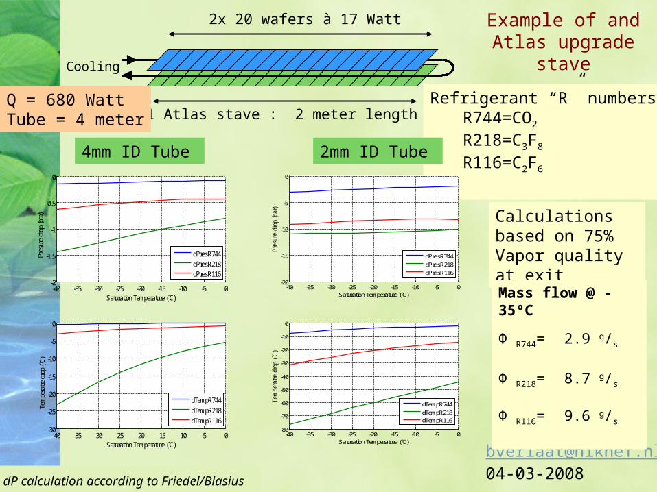
2x 20 wafers à 17 Watt
1 Atlas stave : 2 meter length
Cooling
Q = 680 WattTube = 4 meter
Calculations based on 75% Vapor quality at exit
Example of and Atlas upgrade
stave
Mass flow @ -35ºC
Φ R744= 2.9 g/s
Φ R218= 8.7 g/s
Φ R116= 9.6 g/s
dP calculation according to Friedel/Blasius
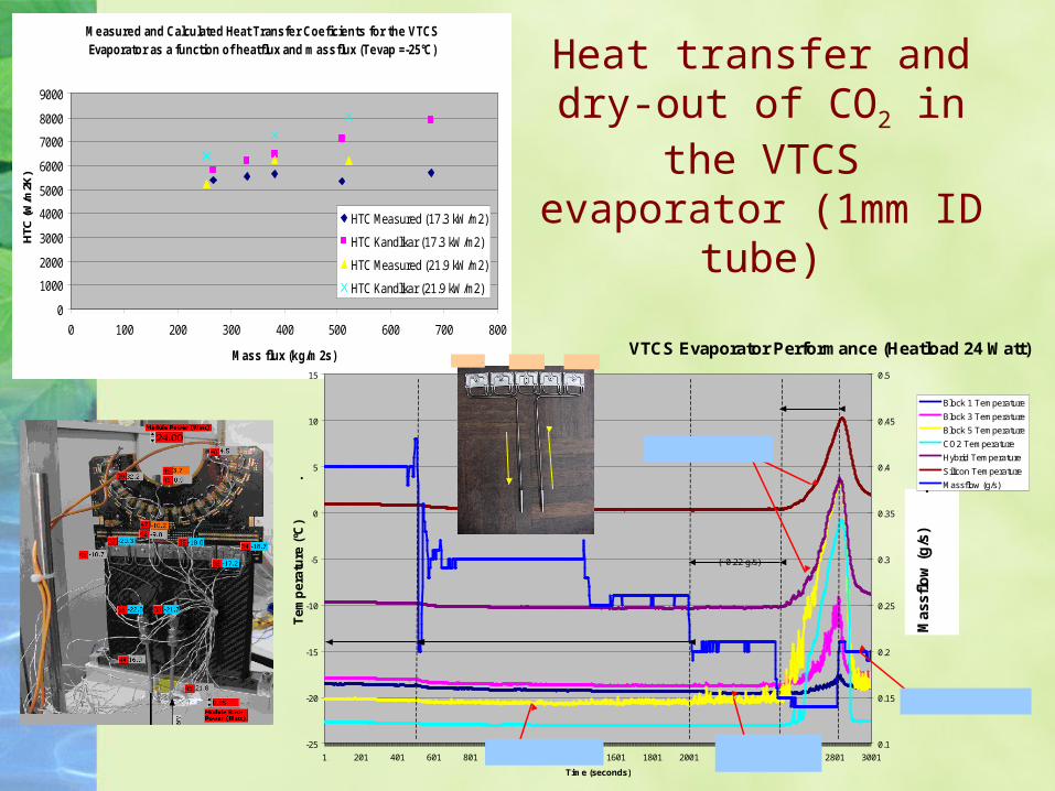
Measured and Calculated Heat Transfer Coeficients for the VTCS Evaporator as a function of heatflux and massflux (Tevap =-25°C)
0
1000
2000
3000
4000
5000
6000
7000
8000
9000
0 100 200 300 400 500 600 700 800
Mass flux (kg/m2s)
HTC
(W/m
2K)
HTC Measured (17.3 kW/m2)
HTC Kandlikar (17.3 kW/m2)
HTC Measured (21.9 kW/m2)
HTC Kandlikar (21.9 kW/m2)
VTCS Evaporator Performance (Heatload 24 Watt)
-25
-20
-15
-10
-5
0
5
10
15
1 201 401 601 801 1001 1201 1401 1601 1801 2001 2201 2401 2601 2801 3001
Time (seconds)
Te
mp
era
ture
(ºC
)
.
0.1
0.15
0.2
0.25
0.3
0.35
0.4
0.45
0.5
Mas
sflo
w (
g/s
)
.
Block 1 Temperature
Block 3 Temperature
Block 5 Temperature
CO2 Temperature
Hybrid Temperature
Silicon Temperature
Massflow (g/s)
Nominal flow condition Reduced flow condition
Critical Flow condition
(~0.22 g/s)
Serious dry-out
Flow increase restoresmodule and silicon temperature.
Module and silicon temperature is seriously affected by dry-out.
Last cooling block shows serious signs of dry-out, module is not yet affected
Last cooling block shows the first signs of a near dry-out
Block 1Block 3Block 5
Heat transfer and dry-out of CO2 in the VTCS evaporator (1mm ID
tube)
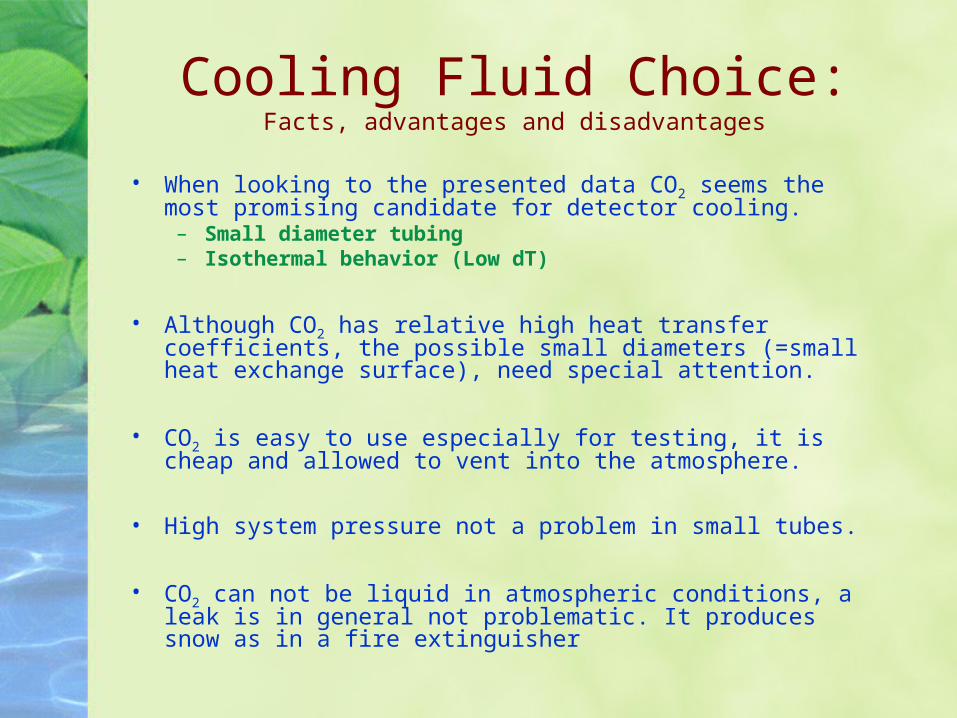
Cooling Fluid Choice:Facts, advantages and disadvantages
• When looking to the presented data CO2 seems the most promising candidate for detector cooling.– Small diameter tubing– Isothermal behavior (Low dT)
• Although CO2 has relative high heat transfer coefficients, the possible small diameters (=small heat exchange surface), need special attention.
• CO2 is easy to use especially for testing, it is cheap and allowed to vent into the atmosphere.
• High system pressure not a problem in small tubes.
• CO2 can not be liquid in atmospheric conditions, a leak is in general not problematic. It produces snow as in a fire extinguisher
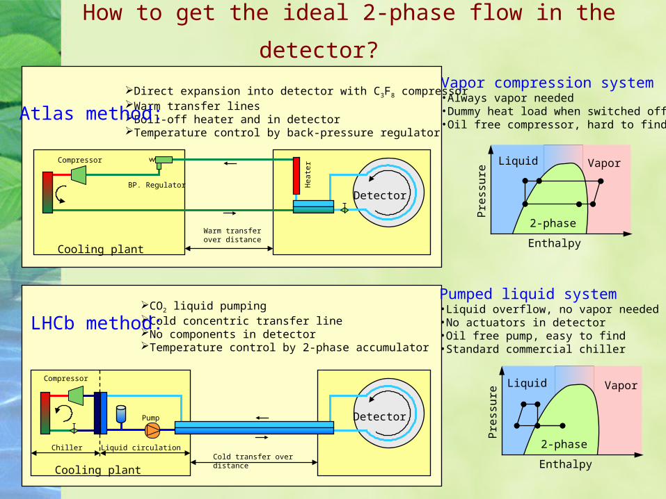
How to get the ideal 2-phase flow in the
detector?
Detector
Cooling plant
Warm transfer over distance
Detector
Cooling plant
Chiller Liquid circulationCold transfer over distance
Direct expansion into detector with C3F8 compressorWarm transfer linesBoil-off heater and in detectorTemperature control by back-pressure regulator
CO2 liquid pumpingCold concentric transfer lineNo components in detectorTemperature control by 2-phase accumulator
LHCb method:
Atlas method:
Liquid Vapor
2-phase
Pre
ssu
re
Enthalpy
Liquid Vapor
2-phase
Pre
ssu
re
Enthalpy
Vapor compression system•Always vapor needed•Dummy heat load when switched off•Oil free compressor, hard to find
Pumped liquid system•Liquid overflow, no vapor needed•No actuators in detector•Oil free pump, easy to find•Standard commercial chiller
Hea
terCompressor
Pump
Compressor
BP. Regulator
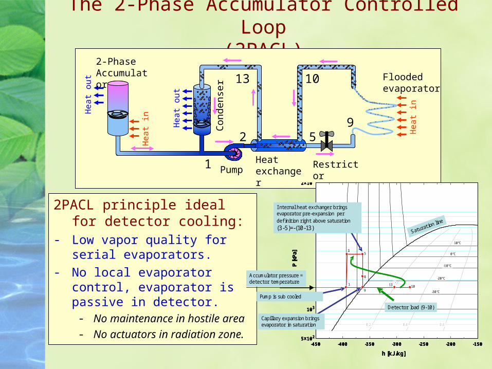
The 2-Phase Accumulator Controlled Loop(2PACL)
2PACL principle ideal for detector cooling:
- Low vapor quality for serial evaporators.
- No local evaporator control, evaporator is passive in detector. - No maintenance in hostile area- No actuators in radiation zone.
Con
dens
er
PumpHeat exchanger
Flooded evaporator
Restrictor
2-Phase Accumulator
He
at
in
He
at
in
He
at
ou
t
He
at
ou
t
1
2 59
1013
-450 -400 -350 -300 -250 -200 -1505x102
103
104
2x10⁴
h [kJ/kg]
P [k
Pa]
-40°C
-30°C
-20°C
-10°C
0°C
10°C
0.2 0.4 0.6
Tertiary VTCS in P-H diagram
1
23
4
5
67
Accumulator pressure = detector temperature
I nternal heat exchanger brings evaporator pre-expansion per definition right above saturation(3-5)=-(10-13)
Capillary expansion brings evaporator in saturation
Detector load (9-10)
1013
9
8
53
1
Pump is sub cooled
-450 -400 -350 -300 -250 -200 -1505x102
103
104
2x10⁴
h [kJ/kg]
P [k
Pa]
-40°C
-30°C
-20°C
-10°C
0°C
10°C
0.2 0.4 0.6
Tertiary VTCS in P-H diagram
1
23
4
5
67
-450 -400 -350 -300 -250 -200 -1505x102
103
104
2x10⁴
h [kJ/kg]
P [k
Pa]
-40°C
-30°C
-20°C
-10°C
0°C
10°C
0.2 0.4 0.6
Tertiary VTCS in P-H diagram
1
23
4
5
67
Accumulator pressure = detector temperature
I nternal heat exchanger brings evaporator pre-expansion per definition right above saturation(3-5)=-(10-13)
Capillary expansion brings evaporator in saturation
Detector load (9-10)
1013
9
8
53
1
Pump is sub cooled
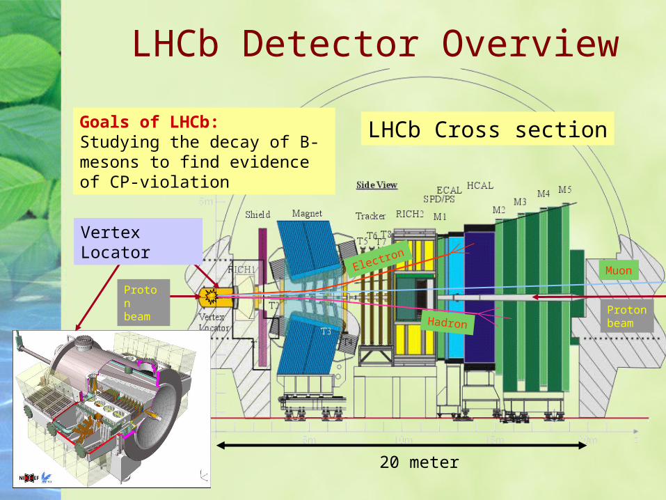
Electron
HadronProton beam
Proton beam
LHCb Detector Overview
Muon
LHCb Cross sectionGoals of LHCb:Studying the decay of B-mesons to find evidence of CP-violation
20 meter
Vertex Locator
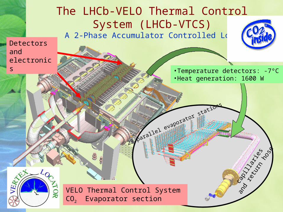
VELO Thermal Control System CO2 Evaporator section
Detectors and electronics
23 parallel evaporator stations
capi
llarie
s
and
retu
rn h
ose
•Temperature detectors: -7ºC •Heat generation: 1600 W
The LHCb-VELO Thermal Control System (LHCb-VTCS)
A 2-Phase Accumulator Controlled Loop
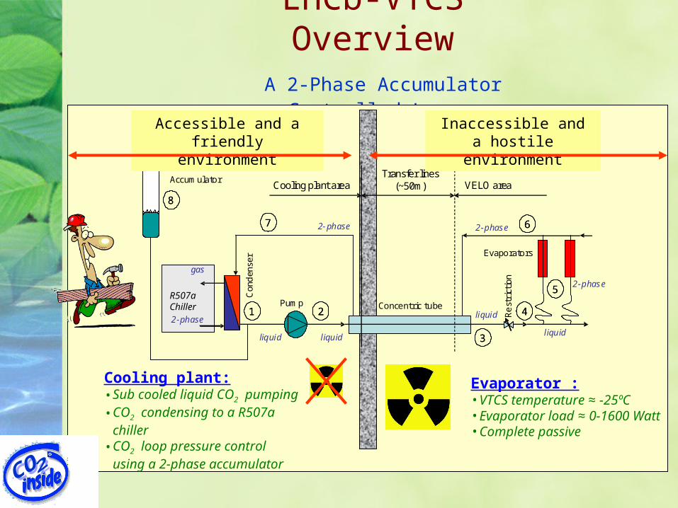
LHCb-VTCS Overview A 2-Phase Accumulator Controlled
Loop
2-phase
gas
R404a chiller
22
33
6677
11
88
44
2-phase2-phase
liquid liquid liquid
2-phase
Con
den
ser Evaporators
Concentric tubePump
Rest
rict
ion
AccumulatorCooling plant area
Transfer lines(~50m) VELO area
55
liquid
Evaporator :• VTCS temperature ≈ -25ºC• Evaporator load ≈ 0-1600 Watt• Complete passive
Cooling plant:• Sub cooled liquid CO2 pumping• CO2 condensing to a R507a
chiller• CO2 loop pressure control
using a 2-phase accumulator
Accessible and a friendly environment
Inaccessible and a hostile environment
R507aChiller
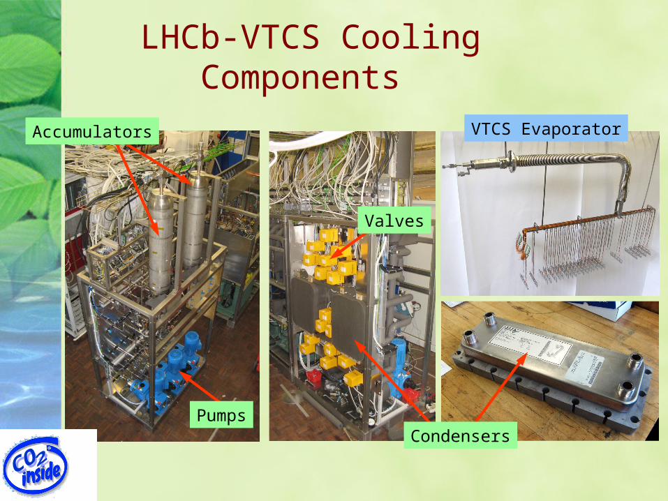
LHCb-VTCS Cooling Components
VTCS Evaporator
Pumps
Accumulators
Condensers
Valves
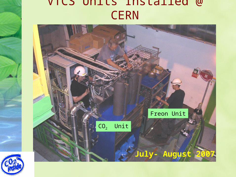
VTCS Units Installed @ CERN
July- August 2007
CO2 Unit
Freon Unit
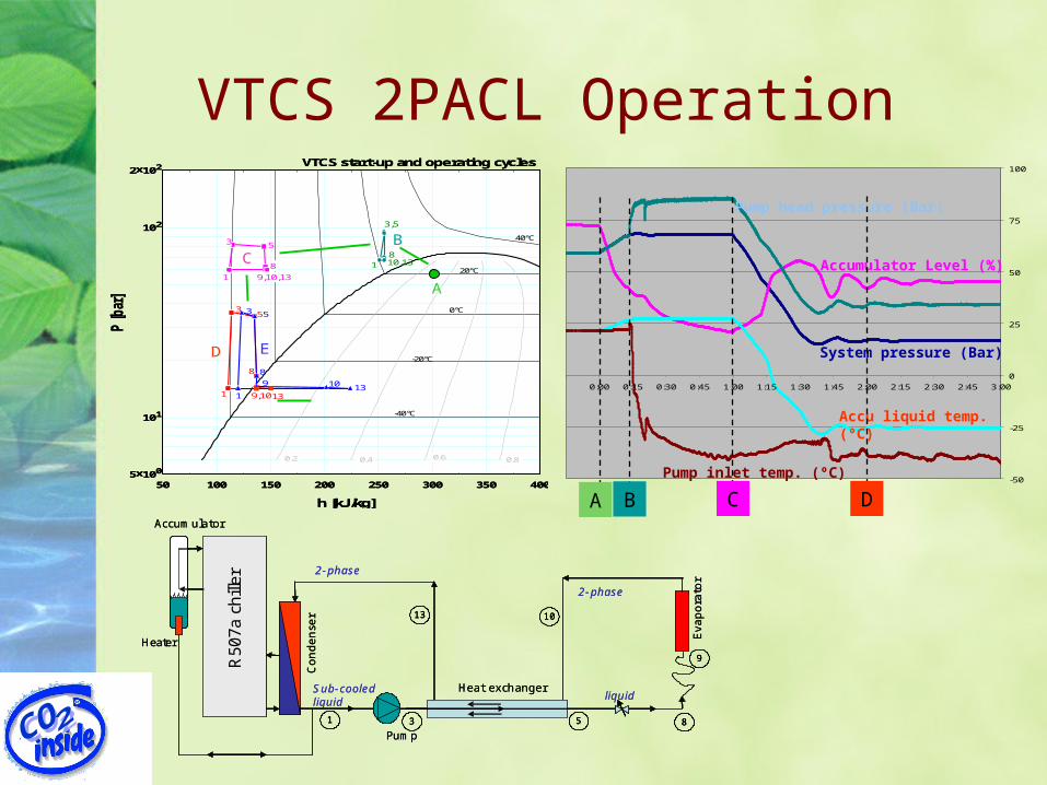
VTCS 2PACL Operation
50 100 150 200 250 300 350 4005x100
101
102
2x10²
h [kJ/kg]
P [bar
]
-40°C
-20°C
0°C
20°C
40°C
0.2 0.4 0.6 0.8
VTCS start-up and operating cycles
1
3,5
810,13
1
3 5
8
9,10,13
1
35
8
9,10131
3 5
8
9 10 13
CB
D E
A
50 100 150 200 250 300 350 4005x100
101
102
2x10²
h [kJ/kg]
P [bar
]
-40°C
-20°C
0°C
20°C
40°C
0.2 0.4 0.6 0.8
VTCS start-up and operating cycles
1
3,5
810,13
1
3 5
8
9,10,13
1
35
8
9,10131
3 5
8
9 10 13
CB
D E
A
-50
-25
0
25
50
75
100
0:00 0:15 0:30 0:45 1:00 1:15 1:30 1:45 2:00 2:15 2:30 2:45 3:00
Pump head pressure (Bar)
System pressure (Bar)
Accumulator Level (%)
Accu liquid temp. (ºC)
Pump inlet temp. (ºC)
A B C D
2-phase
2-phase
Sub-cooledliquid
Condense
r
Evapora
tor
Pump
Accumulator
liquid
Heater
Heat exchanger
R50
7a
chill
er
1 3
10
9
85
13
2-phase
2-phase
Sub-cooledliquid
Condense
r
Evapora
tor
Pump
Accumulator
liquid
Heater
Heat exchanger
R50
7a
chill
er
11 33
1010
99
8855
1313
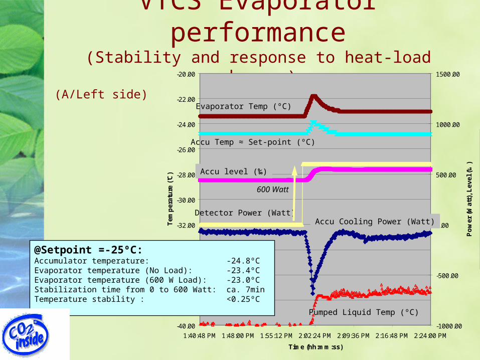
VTCS Evaporator performance
(Stability and response to heat-load changes)
-40.00
-38.00
-36.00
-34.00
-32.00
-30.00
-28.00
-26.00
-24.00
-22.00
-20.00
1:40:48 PM 1:48:00 PM 1:55:12 PM 2:02:24 PM 2:09:36 PM 2:16:48 PM 2:24:00 PM
Time (hh:mm:ss)
Tem
per
atu
re (
'C)
-1000.00
-500.00
0.00
500.00
1000.00
1500.00
Po
wer
(W
att)
, Lev
el (
‰)
VTCS_TL_PT102.P TL_PT102 Accu Pressure
VTCS_TL_PT102.P Tsat(TL_PT102)
VTCS_TL_PT104.P TL_PT104 Pump HeadPressure
VTCS_TL_TT045.T TL_TT045 Evaporator
VTCS_TL_TT112.T TL_TT112 CO2 Pump InletTemperature
VTCS_TL_HT105.Power TL_HT105 AccuHeater
VTCS_TL_LT101.Level TL_LT101 Level
VTCS_TL_TT125.T TL_Detector heater
Evaporator Temp (ºC)
Accu Temp ≈ Set-point (ºC)
Detector Power (Watt)
600 Watt
Accu level (‰)
Accu Cooling Power (Watt)
Pumped Liquid Temp (ºC)
@Setpoint =-25ºC:Accumulator temperature: -24.8ºC Evaporator temperature (No Load): -23.4ºCEvaporator temperature (600 W Load): -23.0ºCStabilization time from 0 to 600 Watt: ca. 7minTemperature stability : <0.25ºC
(A/Left side)
VTCS Transfer line Operation(Internal heat exchanger)
-50
-25
0
25
50
75
0:00 0:15 0:30 0:45 1:00 1:15 1:30 1:45 2:00 2:15 2:30 2:45 3:00
[10] Evaporator pressure (Bar)
[13] Condenser Inlet (ºC)
[1] Pump inlet (ºC)
2-phase
gas
R507a chiller
1
2-phase
2-phase
liquid
2-phase
Condense
r
Evapora
tor
Concentric tube
Pump
Rest
rict
ion
Accumulator
liquid
2
3 4
10
9
8765
11
1214
13
2-phase
gas
Transfer lines(Ca. 50m)Cooling plant area VELO area Inside VELO
Heater
By-p
ass
2-phase
gas
R507a chiller
11
2-phase
2-phase
liquid
2-phase
Condense
r
Evapora
tor
Concentric tube
Pump
Rest
rict
ion
Accumulator
liquid
22
33 44
1010
99
88776655
1111
12121414
1313
2-phase
gas
Transfer lines(Ca. 50m)Cooling plant area VELO area Inside VELO
Heater
By-p
ass
Acc
umul
ator
se
t-po
int
[5] Evaporator liquid in (ºC)
A B C
B
C
Transfer line temperature profile
A: Condenser and evaporator single phase
B: Evaporator 2-phase, condenser single phase
C: Both evaporator and Condenser 2- phase
[14] Accumulator pressure (Bar)
[10] Evaporative temp. (ºC)
A
Eva
pora
tor
side
Coo
ling
pla
nt s
ide
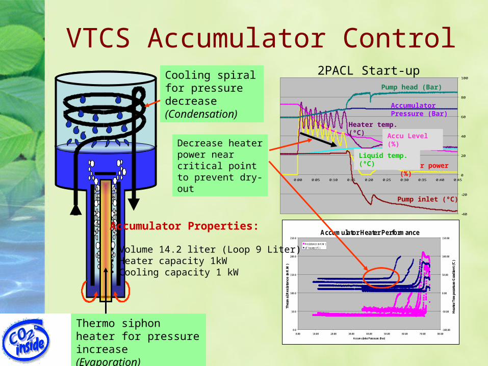
VTCS Accumulator Control
Accumulator Heater Performance
0.0
50.0
100.0
150.0
200.0
250.0
0.00 10.00 20.00 30.00 40.00 50.00 60.00 70.00 80.00
Accumulator Pressure (Bar)
Ther
mal
Res
ista
nce
(mK
/W)
-100.00
-50.00
0.00
50.00
100.00
150.00
Hea
ter
Tem
pera
ture
Gra
dien
t ('C
)
Resistance (mK/W)
dT heater (ºC)
1000 W750 W
500 W
400 W
250 W
100 W
Resistance @ 1000, 750, 500, 400 & 250 W
Resistance @ 100 W
-40
-20
0
20
40
60
80
100
0:00 0:05 0:10 0:15 0:20 0:25 0:30 0:35 0:40 0:45
2PACL Start-up
Heater power (%)
Accu Level (%)
Heater temp. (ºC)
Liquid temp. (ºC)
Pump inlet (ºC)
Accumulator Pressure (Bar)
Pump head (Bar)
Decrease heater power near critical point to prevent dry-out
Thermo siphon heater for pressure increase(Evaporation)
Cooling spiral for pressure decrease(Condensation)
Accumulator Properties:
• Volume 14.2 liter (Loop 9 Liter)• Heater capacity 1kW• Cooling capacity 1 kW
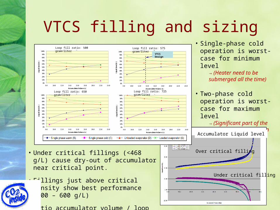
VTCS filling and sizing• Single-phase cold operation
is worst-case for minimum level
→ (Heater need to be submerged all the time)
• Two-phase cold operation is worst-case for maximum level
→ (Significant part of the cooling coil need to be in vapor phase)
Over critical filling
Under critical filling
Accumulator Liquid level
(Fill rate 500 gram/liter)
0%
10%
20%
30%
40%
50%
60%
70%
80%
90%
100%
8.0 10.0 12.0 14.0 16.0 18.0 20.0 22.0 24.0
Accumulator Volume (L)
Liq
uid
leve
l (%
)
.
(Fill rate 575 gram/liter)
0%
10%
20%
30%
40%
50%
60%
70%
80%
90%
100%
8.0 10.0 12.0 14.0 16.0 18.0 20.0 22.0 24.0
Accumulator Volume (L)
Liq
uid
leve
l (%
)
.
(Fill rate 725 gram/liter)
0%
10%
20%
30%
40%
50%
60%
70%
80%
90%
100%
8.0 10.0 12.0 14.0 16.0 18.0 20.0 22.0 24.0
Accumulator Volume (L)
Liq
uid
leve
l (%
)
.
(Fill rate 650 gram/liter)
0%
10%
20%
30%
40%
50%
60%
70%
80%
90%
100%
8.0 10.0 12.0 14.0 16.0 18.0 20.0 22.0 24.0
Accumulator Volume (L)
Liq
uid
leve
l (%
)
.
VTCS Design
Loop fill ratio: 500 gram/liter
Loop fill ratio: 650 gram/liter Loop fill ratio: 725 gram/liter
Loop fill ratio: 575 gram/liter
• Under critical fillings (<468 g/L) cause dry-out of accumulator near critical point.
• Fillings just above critical density show best performance (500 – 600 g/L)
• Ratio accumulator volume / loop volume: >1.5 (AMS-TTCS & LHCb-VTCS)
Conclusions• CO2 is a very good cooling fluid for detector cooling
– Low thermal gradients– Small tube sizes– High heat transfer
• The 2PACL method turned out to be a good method for circulating the cooling fluid.– Easy to operate– Standard industrial components– Stable operation– Large operational temperature range– Passive in detector– Heat load independent– Easy start-up and cool-down procedure
• 2PACL is easy to set-up and use. This is ideal for lab-experiments.
• Not proven, but the 2PACL method it must work for other fluids too.
What brings the future (1) ?
• Future projects at NIKHEF:– Development of a desktop CO2 cooler for
laboratory and prototype use. (<1kW@-35’C)
– Upgrade Altas SCT cooling (CO2?)
– Small cooling projects: Medipix,.... – Studies on small cooling pipes. Understand
the pro‘s & con’s. Verify lacking theory.• Heat exchange• Flow pattern Cooperation with CMS? • Pressure drop
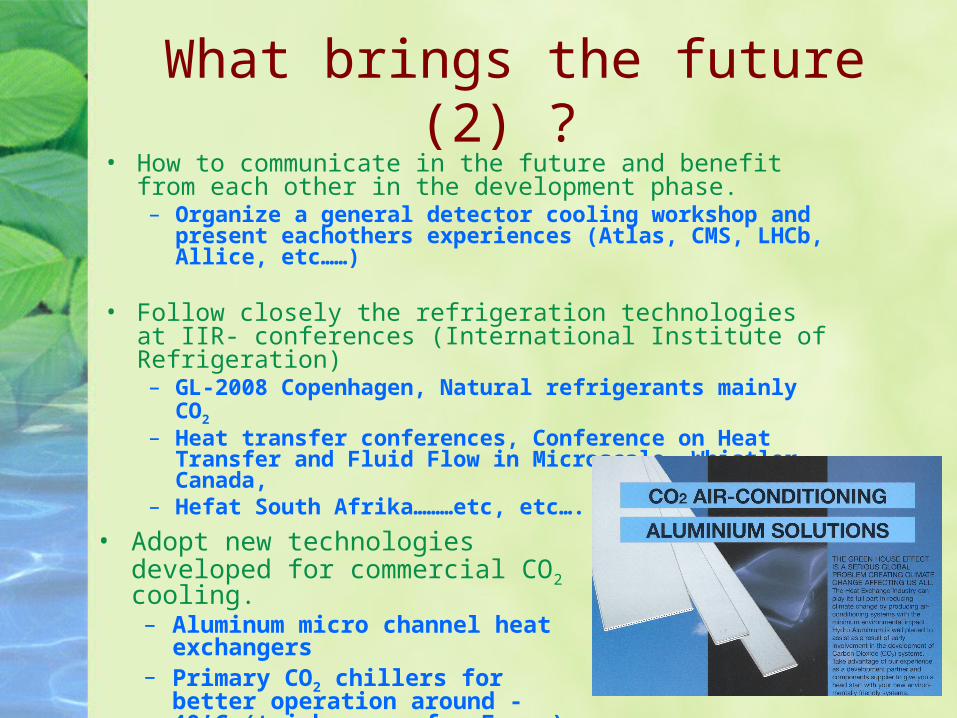
What brings the future (2) ? • How to communicate in the future and benefit from
each other in the development phase.– Organize a general detector cooling workshop
and present eachothers experiences (Atlas, CMS, LHCb, Allice, etc……)
• Follow closely the refrigeration technologies at IIR- conferences (International Institute of Refrigeration)– GL-2008 Copenhagen, Natural refrigerants
mainly CO2
– Heat transfer conferences, Conference on Heat Transfer and Fluid Flow in Microscale, Whistler, Canada,
– Hefat South Afrika………etc, etc….• Adopt new technologies
developed for commercial CO2 cooling.– Aluminum micro channel
heat exchangers– Primary CO2 chillers for
better operation around -40’C (tricky area for Freon)