Embed Size (px)
Citation preview
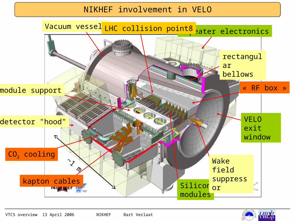
VTCS overview 13 April 2006 NIKHEF Bart Verlaat 1
NIKHEF involvement in VELO
~1 m
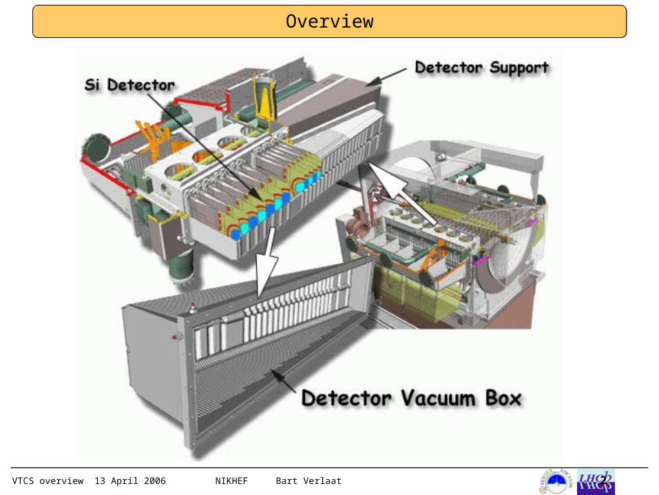
module support
CO2 cooling
detector "hood"
kapton cables
Vacuum vessel repeater electronicsLHC collision point8
« RF box »
rectangular bellows
VELO exit window
Silicon modules
Wake field suppressor
VTCS overview 13 April 2006 NIKHEF Bart Verlaat 2
Overview
VTCS overview 13 April 2006 NIKHEF Bart Verlaat 3
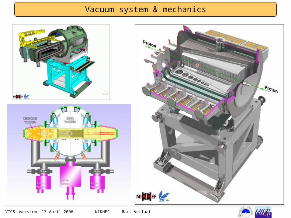
Vacuum system & mechanics
VTCS overview 13 April 2006 NIKHEF Bart Verlaat 4
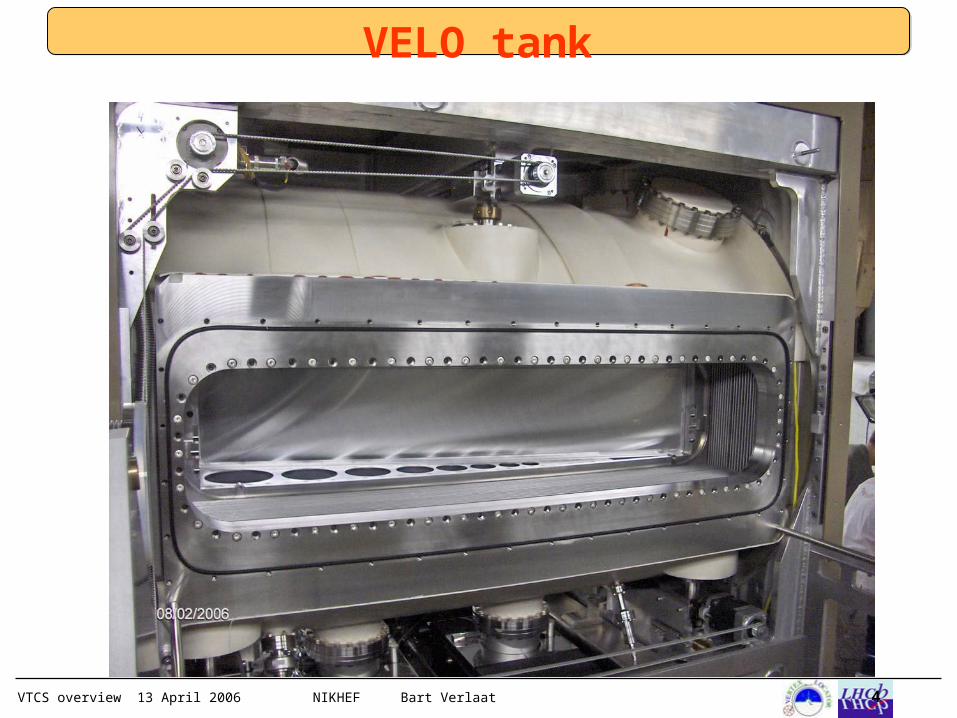
VELO tank
VTCS overview 13 April 2006 NIKHEF Bart Verlaat 5
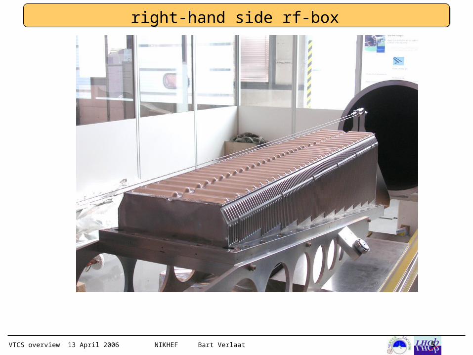
right-hand side rf-box
VTCS overview 13 April 2006 NIKHEF Bart Verlaat 6
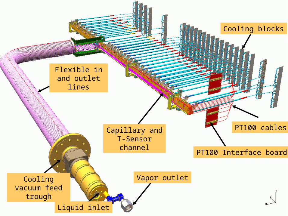
Capillary and T-Sensor channel
Cooling blocks
Flexible in and outlet lines
Cooling vacuum feed
trough
Liquid inlet
Vapor outlet
PT100 Interface board
PT100 cables
VTCS overview 13 April 2006 NIKHEF Bart Verlaat 7
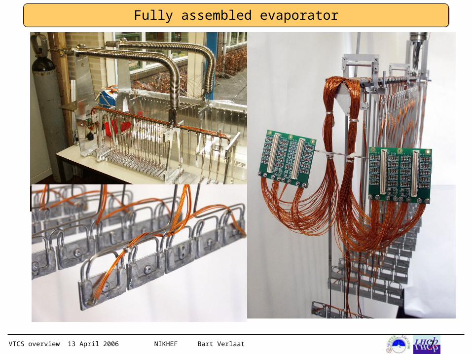
Fully assembled evaporator
VTCS overview 13 April 2006 NIKHEF Bart Verlaat 8
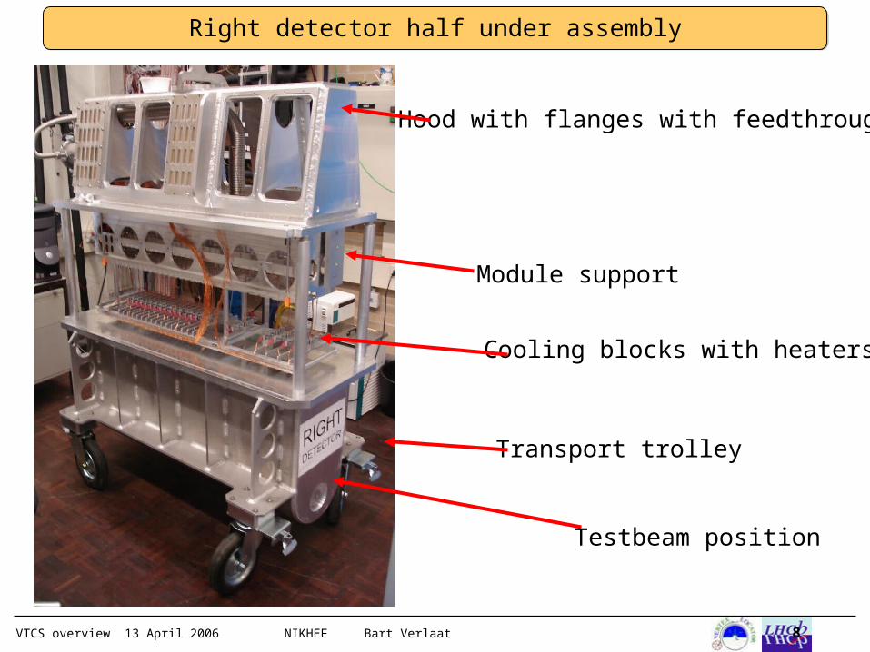
Hood with flanges with feedthroughs
Transport trolley
Testbeam position
Cooling blocks with heaters
Module support
Right detector half under assembly
VTCS overview 13 April 2006 NIKHEF Bart Verlaat 9
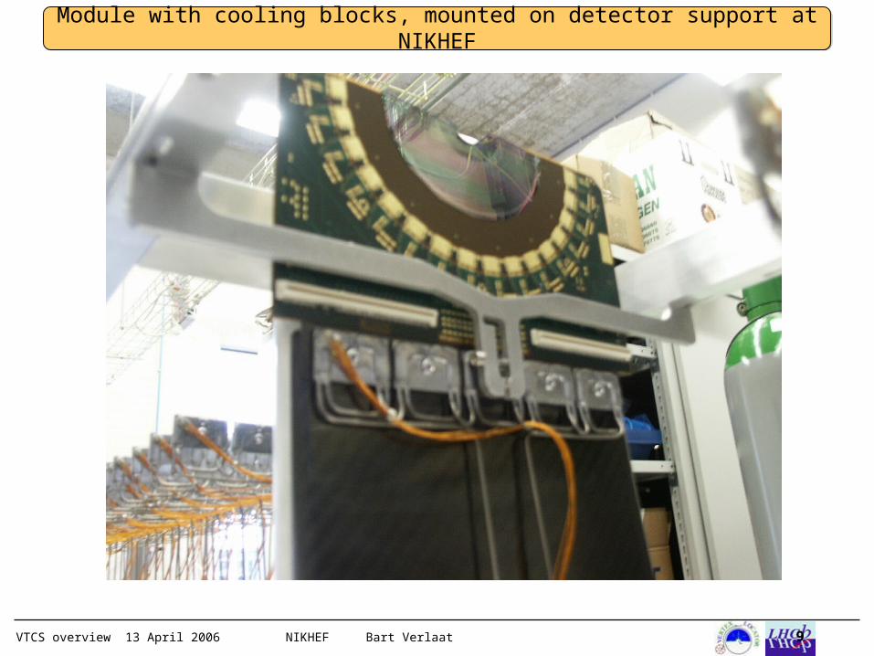
Module with cooling blocks, mounted on detector support at NIKHEF
VTCS overview 13 April 2006 NIKHEF Bart Verlaat 10
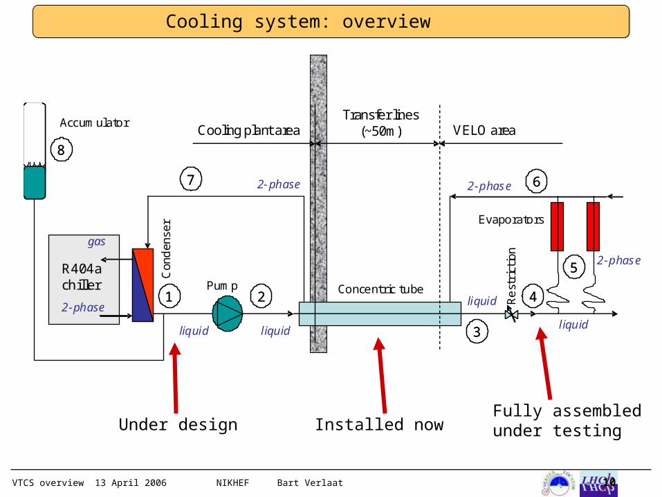
Cooling system: overview
2-phase
gas
R404a chiller
22
33
6677
11
88
44
2-phase2-phase
liquid liquid liquid
2-phase
Con
den
ser Evaporators
Concentric tubePump
Rest
rict
ion
AccumulatorCooling plant area
Transfer lines(~50m) VELO area
55
liquid
Fully assembled under testingInstalled nowUnder design
VTCS overview 13 April 2006 NIKHEF Bart Verlaat 11
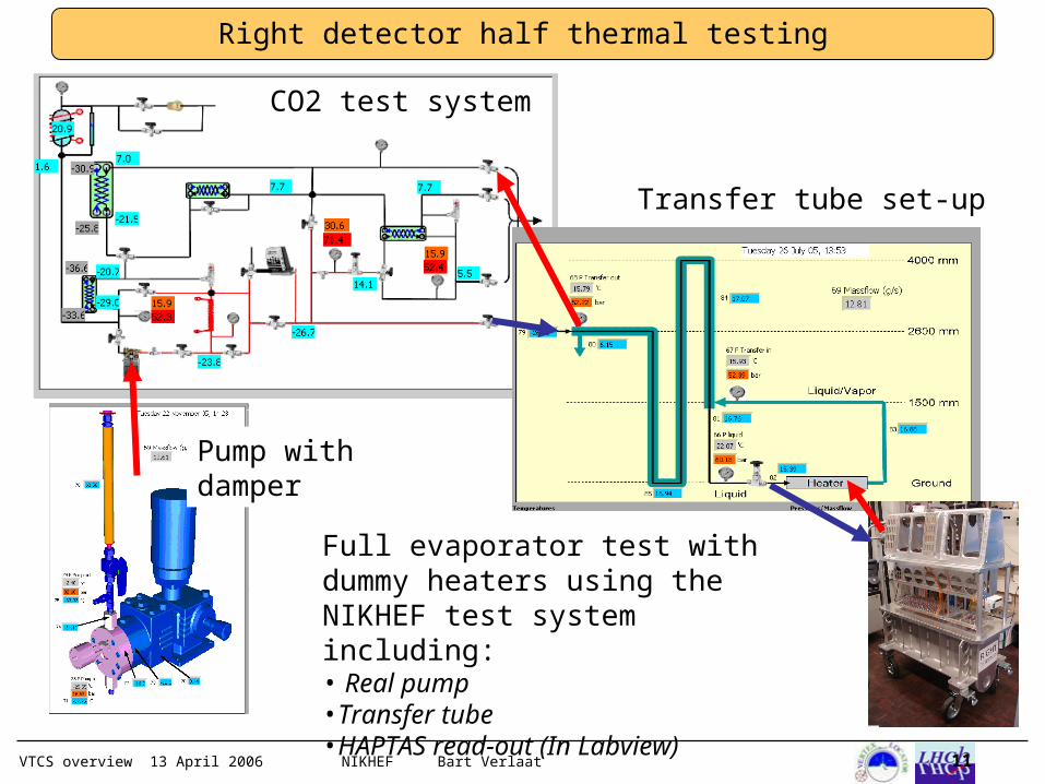
Full evaporator test with dummy heaters using the NIKHEF test system including:• Real pump•Transfer tube•HAPTAS read-out (In Labview)
CO2 test system
Transfer tube set-up
Pump with damper
Right detector half thermal testing
VTCS overview 13 April 2006 NIKHEF Bart Verlaat 12
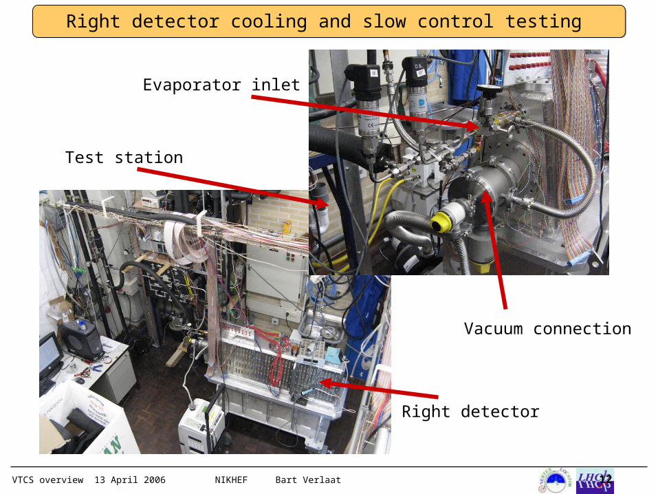
Right detector cooling and slow control testing
Test station
Right detector
Evaporator inlet
Vacuum connection
VTCS overview 13 April 2006 NIKHEF Bart Verlaat 13
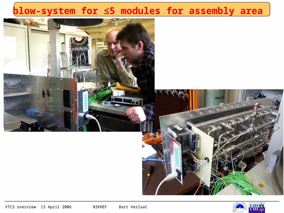
blow-system for ≤5 modules for assembly area
VTCS overview 13 April 2006 NIKHEF Bart Verlaat 14
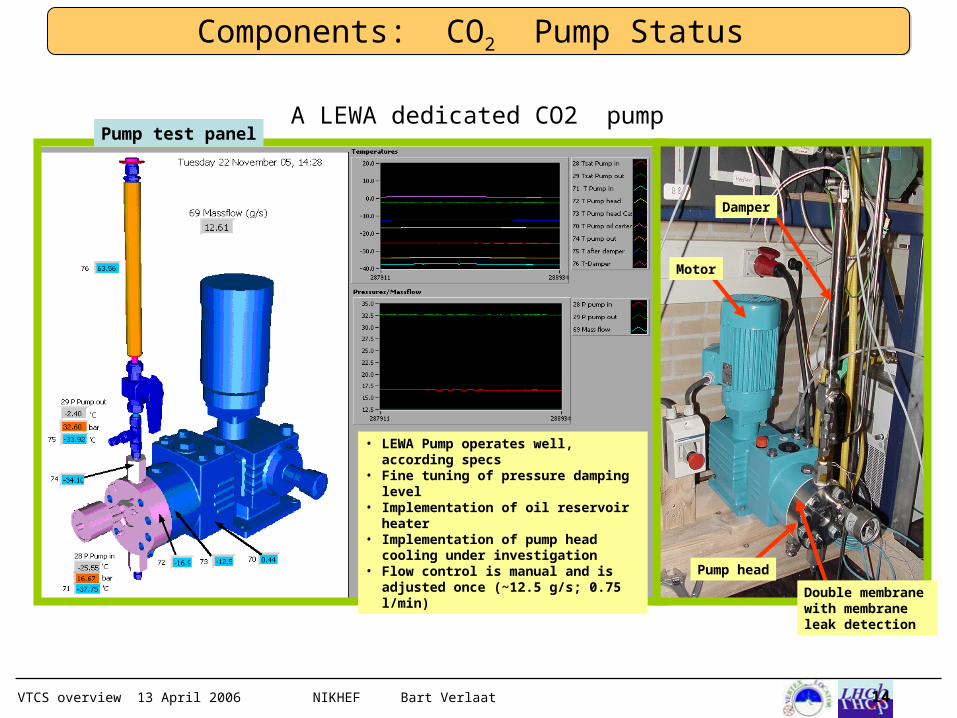
• LEWA Pump operates well, according specs
• Fine tuning of pressure damping level
• Implementation of oil reservoir heater
• Implementation of pump head cooling under investigation
• Flow control is manual and is adjusted once (~12.5 g/s; 0.75 l/min)
Components: CO2 Pump Status
Pump head
Double membrane with membrane leak detection
Motor
Damper
Pump test panelA LEWA dedicated CO2 pump
VTCS overview 13 April 2006 NIKHEF Bart Verlaat 15
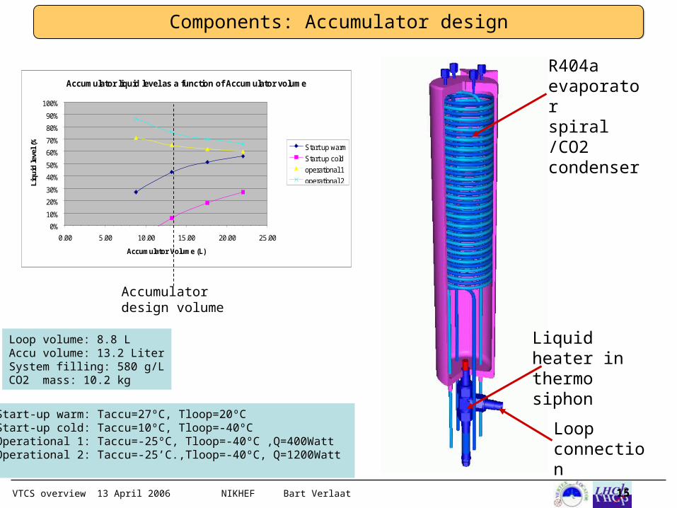
Accumulator liquid level as a function of Accumulator volume
0%
10%
20%
30%
40%
50%
60%
70%
80%
90%
100%
0.00 5.00 10.00 15.00 20.00 25.00
Accumulator Volume (L)
Liqu
id le
vel (
%)
Start up warm
Start up cold
operational 1
operational 2
Components: Accumulator design
R404a evaporator spiral /CO2 condenser
Accumulator design volume
Loop volume: 8.8 LAccu volume: 13.2 LiterSystem filling: 580 g/LCO2 mass: 10.2 kg
Liquid heater in thermo siphon
Loop connection
Start-up warm: Taccu=27ºC, Tloop=20ºC Start-up cold: Taccu=10ºC, Tloop=-40ºCOperational 1: Taccu=-25ºC, Tloop=-40ºC ,Q=400WattOperational 2: Taccu=-25’C.,Tloop=-40ºC, Q=1200Watt
VTCS overview 13 April 2006 NIKHEF Bart Verlaat 16
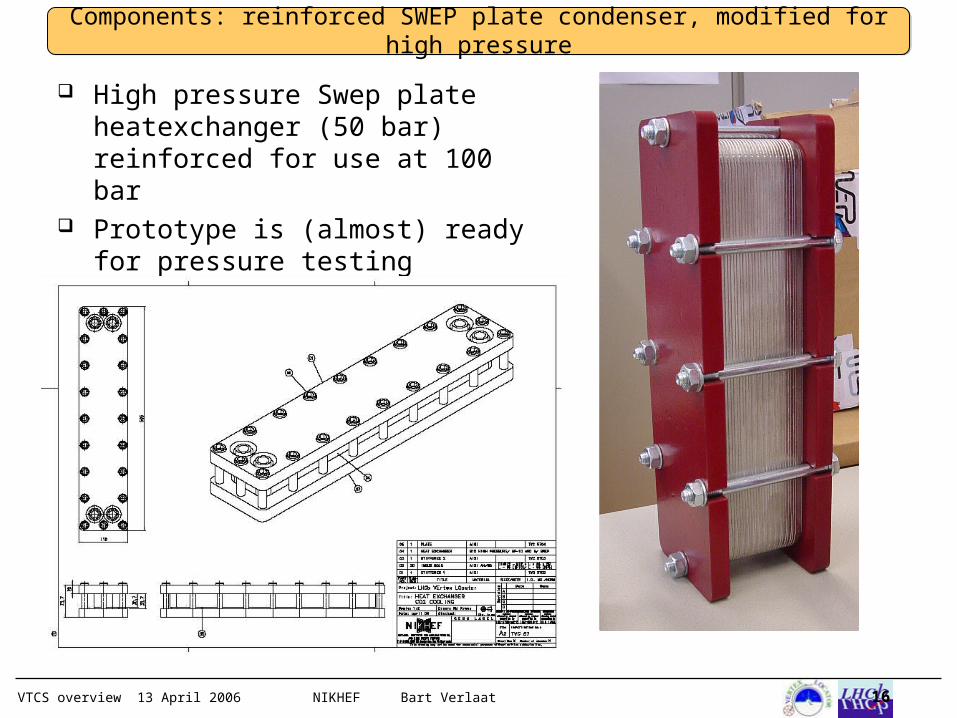
Components: reinforced SWEP plate condenser, modified for high pressure
High pressure Swep plate heatexchanger (50 bar) reinforced for use at 100 bar
Prototype is (almost) ready for pressure testing
VTCS overview 13 April 2006 NIKHEF Bart Verlaat 17
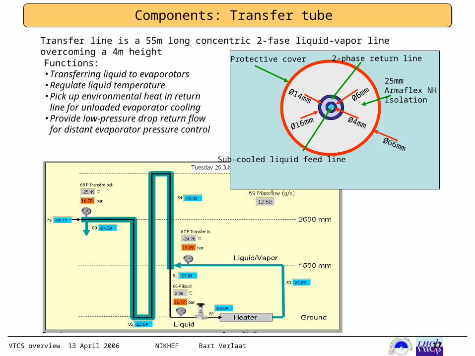
Components: Transfer tube
Ø4mm
Ø6mmØ14mm
Ø16mm
Ø66mm
Sub-cooled liquid feed line
2-phase return line
25mm Armaflex NH Isolation
Protective cover
Transfer line is a 55m long concentric 2-fase liquid-vapor line overcoming a 4m heightFunctions:•Transferring liquid to evaporators•Regulate liquid temperature•Pick up environmental heat in return line for unloaded evaporator cooling
•Provide low-pressure drop return flow for distant evaporator pressure control
VTCS overview 13 April 2006 NIKHEF Bart Verlaat 18
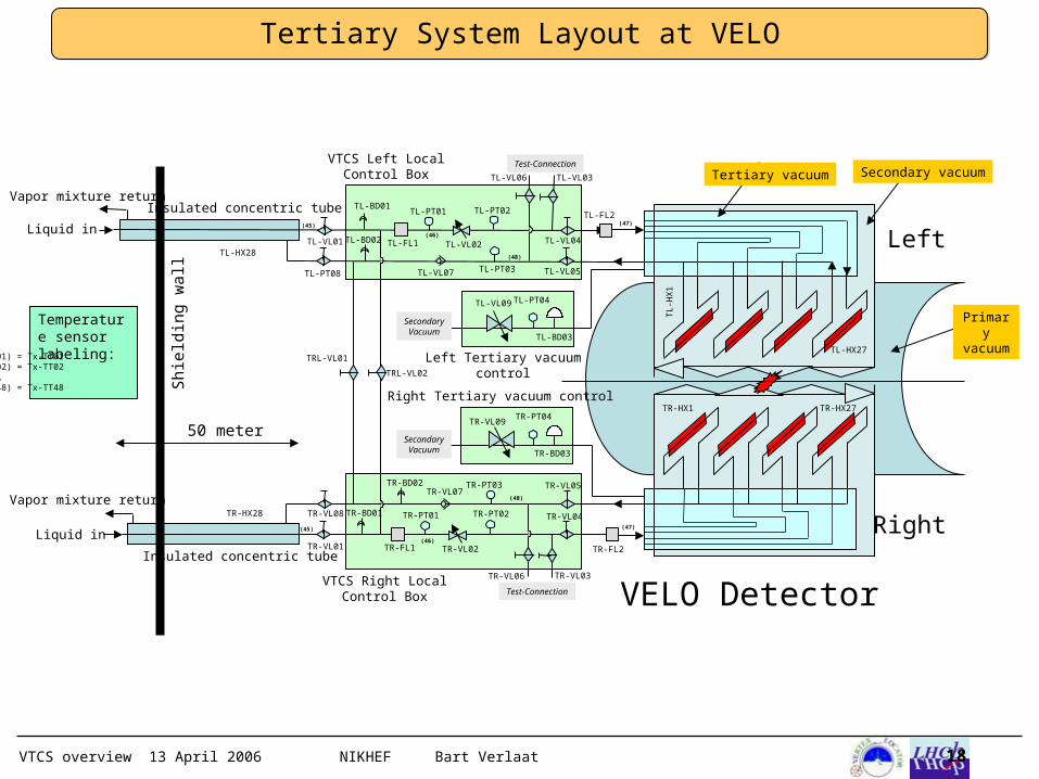
Left
Right
VELO Detector
Insulated concentric tube
TR-PT02
Insulated concentric tube
TR-PT03
50 meter
Shi
eldi
ng w
all
TR-HX28
TR-VL02
TL-PT03TL-PT08
TL-HX28
TL-VL03
TL
-HX
1
TL-HX27
TR-HX1 TR-HX27
TR-PT01
TL-FL2
TR-FL2
VTCS Right Local Control Box
VTCS Left Local Control Box
TL-VL09 TL-PT04
TL-BD03
TR-VL09TR-PT04
TR-BD03
Left Tertiary vacuum control
Right Tertiary vacuum control
Liquid in
Vapor mixture return
Liquid in
Vapor mixture return
Secondary vacuum
Primary vacuu
m
Tertiary vacuum
TR-FL1TR-VL01
TR-VL03TR-VL06
TR-VL05
TR-VL04
TL-VL06
TL-VL04
TL-VL05
TL-VL02TL-FL1TL-VL01
TR-VL08
TRL-VL01
TRL-VL02
TL-PT02TL-PT01
Test-Connection
Test-Connection
TR-VL07
TL-VL07
Secondary
Vacuum
Secondary
Vacuum
TL-BD01
TL-BD02
TR-BD01
TR-BD02
(48)
(45)
(46)
(47)
(48)
(45)
(46)
(47)
(01) = Tx-TT01(02) = Tx-TT02……(48) = Tx-TT48
Temperature sensor labeling:
Tertiary System Layout at VELO
VTCS overview 13 April 2006 NIKHEF Bart Verlaat 19
TR-AC101
TR-PM101
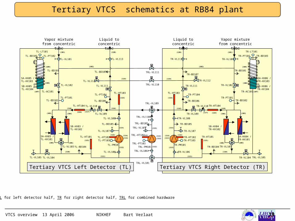
Tertiary VTCS Right Detector (TR)
TR-PT101TR-PT104
TR-PT102TR-VL101
TR-VL103
TR-VL104 TRL-VL105
TR-VL106
TR-VL107
TR-VL108
TR-VL109
TR-VL110
TR-VL111
TR-VL113
TR-LT101
TR-BD103
SA-HX04 / TR-HX101
SB-HX04 / TR-HX102
SA-HX06 / TR-HX103
TL-HT103
TR-HT104
SB-HX06 / TR-HX104
TR-HT101
TR-BD105
TR-VL102
TR-PT103TR-HT102
TR-BD101
TR-BD102
TR-BD104
TR-BD106
TR-BD107
TRL-VL101
TRL-PM101
TRL-VL107
TRL-VL109
TRL-VL110
TRL-VL111
Liquid to concentric tube
Vapor mixture from concentric
tube
Vapor mixture from concentric
tube
Liquid to concentric tube
TL-AC101
TL-PM101
Tertiary VTCS Left Detector (TL)
TL-PT101TL-PT104
TL-PT102TL-VL101
TL-VL103
TL-VL104TL-VL105
TL-VL106
TL-VL107
TL-VL108
TL-VL109
TL-VL110
TL-VL111
TL-VL113
TL-LT101
TL-BD103
SA-HX03 / TL-HX101
SB-HX03 / TL-HX102
SA-HX05 / TL-HX103
TL-HT103
TL-HT104
SB-HX05 / TL-HX104
TL-HT101
TL-BD105
TL-VL102
TL-PT103TL-HT102
TL-BD101
TL-BD102
TL-BD104
TL-BD106
TL-BD107
TRL-VL106
TRL-VL1108
TRL-BD105
TRL-PT103
TRL-HT102
(101)
(103) (104)
(106)(105)
(111)
(112)
(115)
(116)
(117)
(118)
(121)
(123)
(122) (114)
(113)
(120)
(107)
(102)
(119)
(110)
(108)
(109)
(101)
(103)(104)
(106) (105)
(111)
(112)
(115)
(116)
(117)
(118)
(121)
(123)
(122)(114)
(113)
(120)
(107)
(102)
(119)
(110)
(108)
(109)
Tx = TL for left detector half, TR for right detector half, TRL for combined hardware
(124) (124)
(112)
(115)
(122) (114)
(113)
TL-VL112 TR-VL112
Tertiary VTCS schematics at RB84 plant
VTCS overview 13 April 2006 NIKHEF Bart Verlaat 20
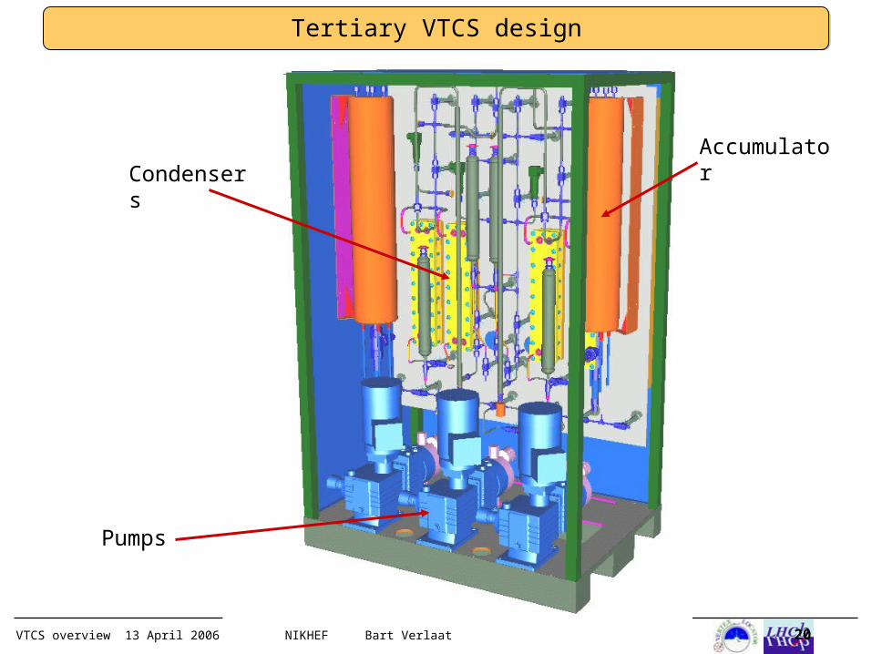
Tertiary VTCS design
Pumps
AccumulatorCondenser
s
VTCS overview 13 April 2006 NIKHEF Bart Verlaat 21
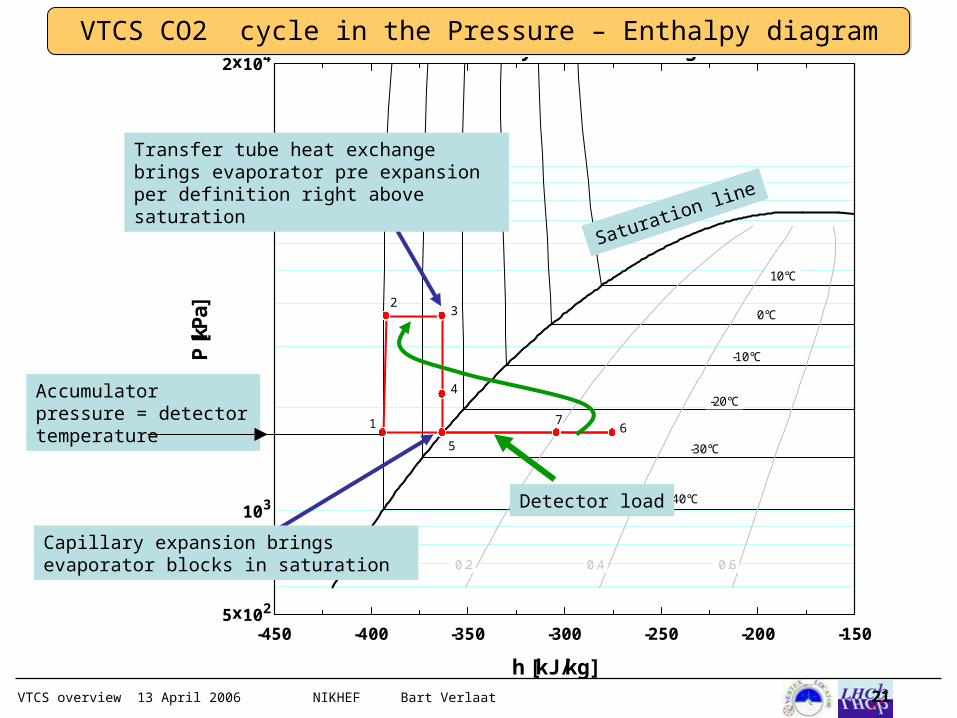
VTCS CO2 cycle in the Pressure – Enthalpy diagram
-450 -400 -350 -300 -250 -200 -1505x102
103
104
2x10⁴
h [kJ/kg]
P [k
Pa]
-40°C
-30°C
-20°C
-10°C
0°C
10°C
0.2 0.4 0.6
Tertiary VTCS in P-H diagram
1
23
4
5
67
Accumulator pressure = detector temperature
Transfer tube heat exchange brings evaporator pre expansion per definition right above saturation
Saturation line
Capillary expansion brings evaporator blocks in saturation
Detector load
VTCS overview 13 April 2006 NIKHEF Bart Verlaat 22
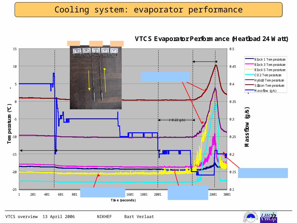
Cooling system: evaporator performance
VTCS Evaporator Performance (Heatload 24 Watt)
-25
-20
-15
-10
-5
0
5
10
15
1 201 401 601 801 1001 1201 1401 1601 1801 2001 2201 2401 2601 2801 3001
Time (seconds)
Te
mp
era
ture
(ºC
)
.
0.1
0.15
0.2
0.25
0.3
0.35
0.4
0.45
0.5
Mas
sflo
w (
g/s
)
.
Block 1 Temperature
Block 3 Temperature
Block 5 Temperature
CO2 Temperature
Hybrid Temperature
Silicon Temperature
Massflow (g/s)
Nominal flow condition Reduced flow condition
Critical Flow condition
(~0.22 g/s)
Serious dry-out
Flow increase restoresmodule and silicon temperature.
Module and silicon temperature is seriously affected by dry-out.
Last cooling block shows serious signs of dry-out, module is not yet affected
Last cooling block shows the first signs of a near dry-out
Block 1Block 3Block 5
VTCS overview 13 April 2006 NIKHEF Bart Verlaat 23
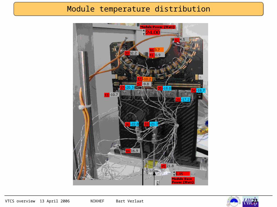
Module temperature distribution
VTCS overview 13 April 2006 NIKHEF Bart Verlaat 24
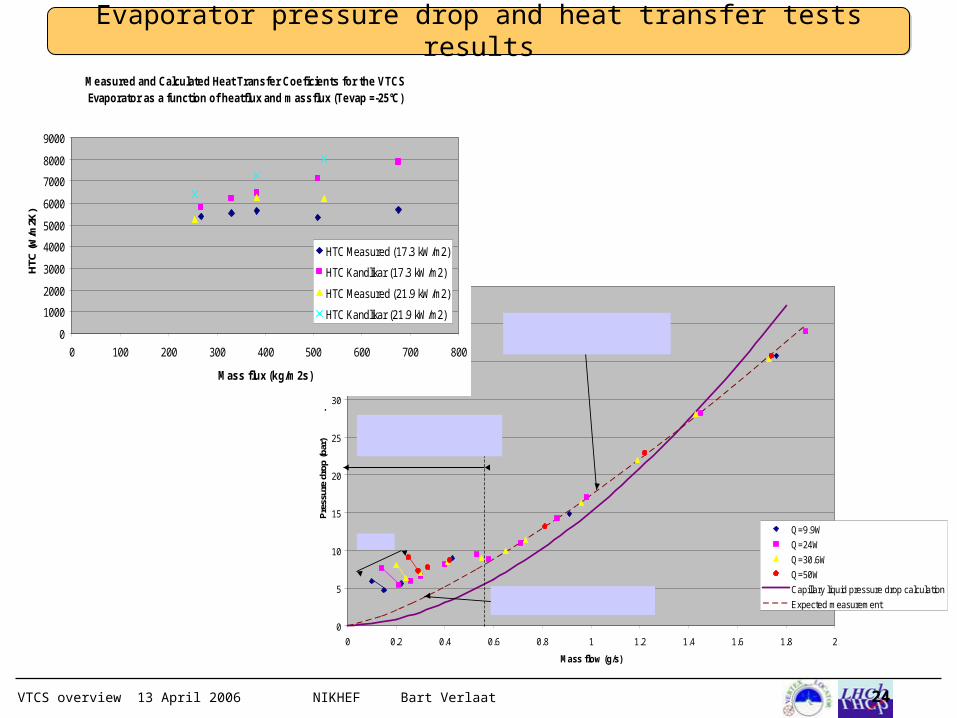
Evaporator pressure drop and heat transfer tests results
0
5
10
15
20
25
30
35
40
45
0 0.2 0.4 0.6 0.8 1 1.2 1.4 1.6 1.8 2
Mass flow (g/s)
Pre
ssur
e dr
op (b
ar)
.
Q=9.9W
Q=24W
Q=30.6W
Q=50W
Capillary liquid pressure drop calculation
Expected measurement
Higher measured pressure drop due to vapor generation in capillaries (Heatleak in test-setup)
Data was expected to be exponential and follow this fit to point zero
Dry-outs
No significant pressuredrop variation due to heatload. Pressure drop is dominated by the capillary => High stability
Measured and Calculated Heat Transfer Coeficients for the VTCS Evaporator as a function of heatflux and massflux (Tevap =-25°C)
0
1000
2000
3000
4000
5000
6000
7000
8000
9000
0 100 200 300 400 500 600 700 800
Mass flux (kg/m2s)
HTC
(W/m
2K)
HTC Measured (17.3 kW/m2)
HTC Kandlikar (17.3 kW/m2)
HTC Measured (21.9 kW/m2)
HTC Kandlikar (21.9 kW/m2)