Embed Size (px)
Citation preview

1
Chapter 2 Circuit element
1. Voltage and current sources.
2. Electrical resistance (Ohm’s law).
3. Construction of a circuit model.
4. Kirchhoff’s laws.
5. Analysis of a circuit containing dependent sources.

2
2.1 Voltage and current sources
• Electrical source : a device that is capable of converting nonelectric energy to electric energy and vice versa.
• Ideal voltage source (2.1(a)) : a circuit element that maintains a prescribed voltage across its terminals regardless of the current flowing in those terminals.
• Ideal current source (2.1(b)) : a circuit element that maintains a prescribed current through its terminals regardless of the voltage across those terminals.

3
Voltage and current sources
• Independent source (2.1) : a voltage or current source in a circuit without relying on voltages or currents elsewhere in the circuit.
• Dependent source (controlled source ; 2.2) : a voltage or current source whose value depends on voltages or currents elsewhere in the circuit.
• Ideal dependent voltage-controlled voltage source (2.2(a)) :
.s xv v

4
Voltage and current sources
• Ideal dependent current-controlled voltage source (2.2(b)) :
• Ideal dependent voltage-controlled current source (2.2(c)) :
• Ideal dependent current-controlled current source (2.2(d)) :
• Active element : a device capable of generating electric energy.
• Passive device : a device that cannot generate electric energy.
.s xv i
.s xi v
.s xi i

5
2.1
• (a) : valid; (b) : valid;
(c) : not permissible;
(d) : not permissible;
(e) : valid.

6
2.2
• (a) : invalid; (b) : valid; (c) : valid; (d) : invalid.

7
2.2 Electric resistance (Ohm’s law)
• Resistance : the capacity of materials to impede or resist the flow of current.
• Resistor (2.5) : a circuit element used to model above behavior.
• Ohm’s law (2.6) :
(figure 2.6(a)), where
the voltage in volts,
the current in amperes,
the resistance in ohms.
(figure 2.6(b)).
v iR
v
i
R
v iR

8
Electric resistance (Ohm’s law)
• Current as a function of the voltage :
• Conductance (siemens (S), mho( )) : the reciprocal of the resistance.
• Power at the terminals of a resistor :
(figure 2.6(a)), (figure 2.6(b)).v v
i iR R
1 S.G
R
2 22 2
2 22 2
( ) (figure 2.6(a)),
( ) (figure 2.6(b)).
v ip vi iR i i R v G
R G
v ip vi iR i i R v G
R G

9
2.3
2 22 2
25
50 (50)2 A, ( 2) (25) 100 W.
25 25d d
d d
v vi P i R
R R
2 22 2
8
(1)(8) 8 V,
(8)(1) (8) 8 W.
8
a
aa
v iR
vp i R
R
2 20.2
(50)(0.2) 10 A,
(50) (0.2) 500 W.
b b
S b
i v G
P v G
2 22 2
20
(1)(20) 20 V,
( 20)(1) (20) 20 W.
20
c c
cc
v i R
vP i R
R

10
2.3 Construction of a circuit model;
• 2.9 flashlight circuit
• 2.10 switch. Short circuit : R=0;
• open circuit : R=infinity.

11
2.5
12
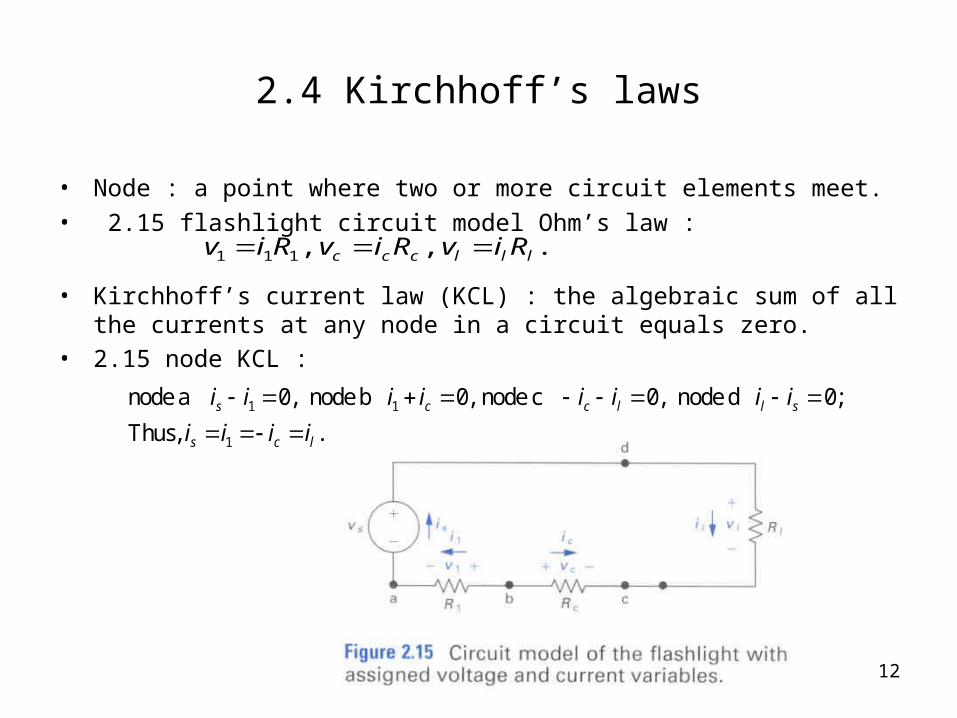
2.4 Kirchhoff’s laws
• Node : a point where two or more circuit elements meet.
• 2.15 flashlight circuit model Ohm’s law :
• Kirchhoff’s current law (KCL) : the algebraic sum of all the currents at any node in a circuit equals zero.
• 2.15 node KCL :
1 1 1, , .c c c l l lv i R v i R v i R
1 1
1
node a 0, node b 0, node c 0, node d 0;
Thus, .s c c l l s
s c l
i i i i i i i i
i i i i
13
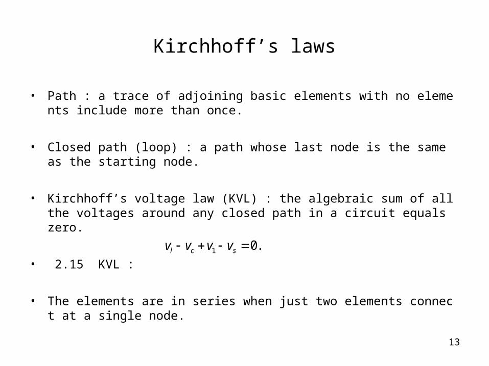
Kirchhoff’s laws
• Path : a trace of adjoining basic elements with no elements include more than once.
• Closed path (loop) : a path whose last node is the same as the starting node.
• Kirchhoff’s voltage law (KVL) : the algebraic sum of all the voltages around any closed path in a circuit equals zero.
• 2.15 KVL :
• The elements are in series when just two elements connect at a single node.
1 0.l c sv v v v

14
• 2.16 KCL :
• 2.17KVL :
1 4 2 5
2 3 1
3 4
5
node a 0,
node b 0,
node c 0,
node d 0.
b a
b c
a c
i i i i
i i i i i
i i i i
i i i
1 2 4 3
3 5
4 6 5
1 2 7
path a 0,
path b 0,
path c 0,
path d 0.
b
a
b c
a c d
v v v v v
v v v
v v v v v
v v v v v v

15
2.8
• 2.19 KCL& KVL.
1 1
1
6 0, 120 10 50 0;
3 A and 3 A.o o
o
i i i i
i i
2 250 10
120V
6A 1 1 1
50 10 120V 6A
(3) 50 450 W, ( 3) (10) 90 W,
120 120( 3) 360 W,
(6) 150(6) 900 W, 50 150 V.
0.
o
p p
p i
p v v i
p p p p

16
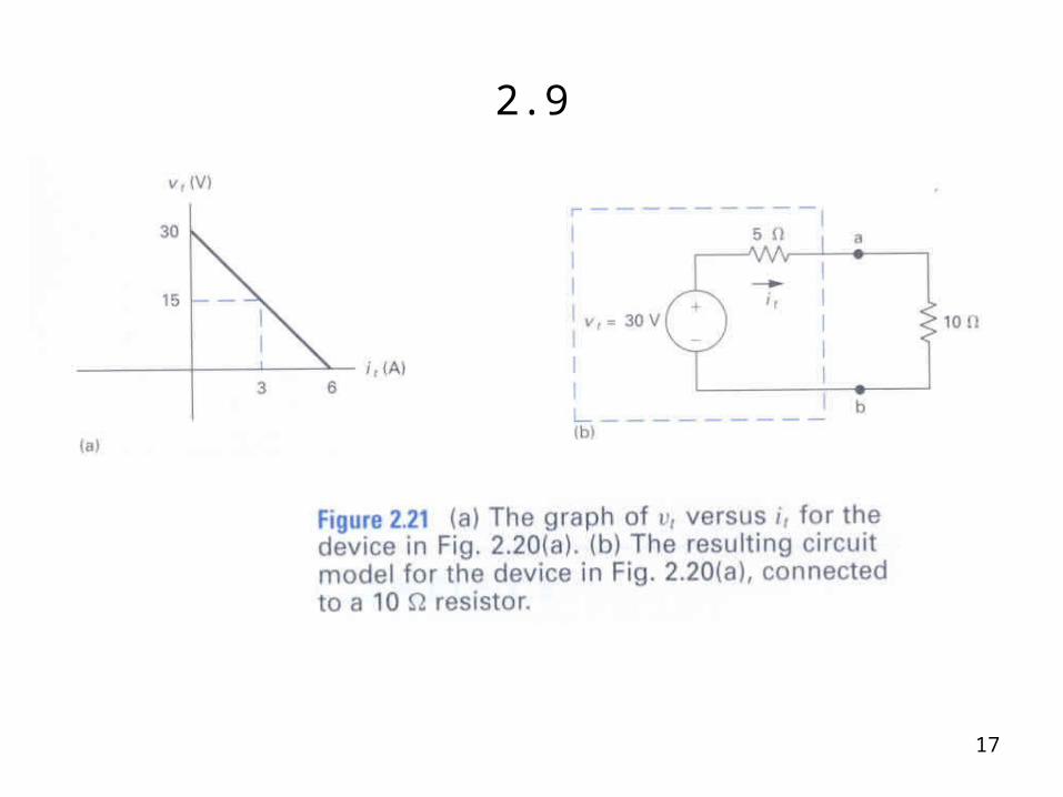
2.9
2.21(b) for 10ohm :
30 5 .t tv i
2 210
30 5 10 , 2 A;
(2) (10) 40 W.
t t ti i i
p i R
17
2.9

18
2.5 Analysis of a circuit containing dependent sources
• 1. Once we know , we can calculate using Ohm’s law.
2. Once we know , we also know the current supplied by the
dependent source .
3. The current in the 500 V source is .
0i 0v
i5i
i

19
Analysis of a circuit containing dependent sources
• 2.22 loop KVL :
• Node b KCL :
500 5 20 .oi i
5 6 .oi i i i
4 A, 24 A,
20 480 V.o
o o
i i
v i

20
2.10
• 2.23 Kirchhoff’s law Ohm’s law.
• KVL :
• Ohm’s law :
• Power :
10 6 , 3 2 3 ; 1.67 A, 1 A.s s o o s oi i i i i i 3 3 V.o ov i
10 3
2 2 26 2 3
10 3 6 2 3
(10)( 1.67) 16.7 W, (3 )( ) (5)( 1) 5 W,
(1.67) (6) 16.7 W, (1) (2) 2 W, (1) (3) 3 W.
16.7 5 16.7 2 3 0 W.
s
s
V i s o
V i
p p i i
p p p
p p p p p

21
2.11
• 2.24 transistor amplifier base current
• KCL :
• Dependent source constraint :
• KVL :
Bi
1 2 1(1) 0, (2) 0, (3) 0.C CC B E B Ci i i i i i i i i
(4) .C Bi i
0 2 2
1 1 2 2
(5) 0,
(6) 0.E E
CC
V i R i R
i R V i R
2 1 2
1 2 1 2
( ) /( ).
( ) /( ) (1 )CC o
BE
V R R R Vi
R R R R R