Embed Size (px)
Citation preview
1
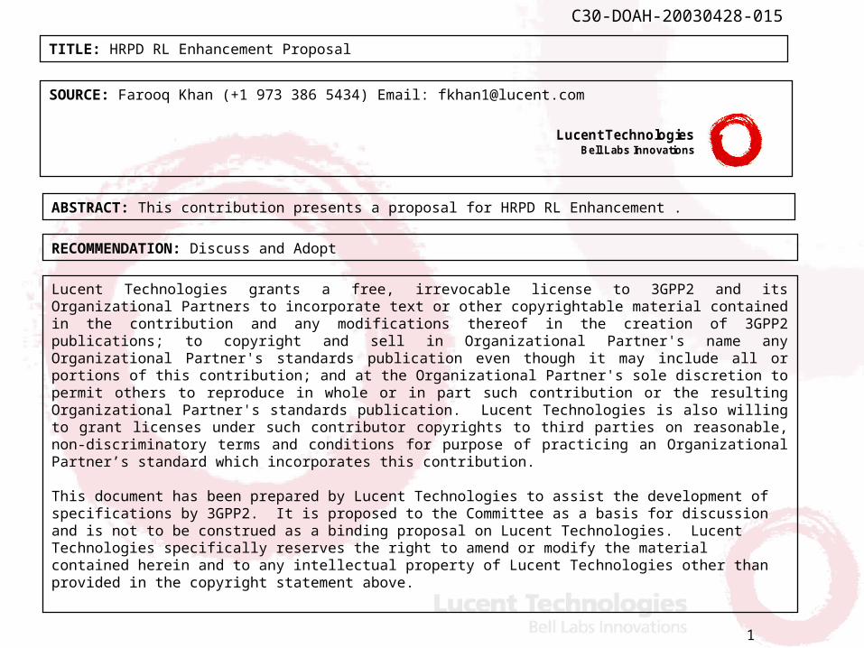
C30-DOAH-20030428-015
TITLE: HRPD RL Enhancement Proposal
SOURCE: Farooq Khan (+1 973 386 5434) Email: [email protected]
Lucent Technologies grants a free, irrevocable license to 3GPP2 and its Organizational Partners to incorporate text or other copyrightable material contained in the contribution and any modifications thereof in the creation of 3GPP2 publications; to copyright and sell in Organizational Partner's name any Organizational Partner's standards publication even though it may include all or portions of this contribution; and at the Organizational Partner's sole discretion to permit others to reproduce in whole or in part such contribution or the resulting Organizational Partner's standards publication. Lucent Technologies is also willing to grant licenses under such contributor copyrights to third parties on reasonable, non-discriminatory terms and conditions for purpose of practicing an Organizational Partner’s standard which incorporates this contribution. This document has been prepared by Lucent Technologies to assist the development of specifications by 3GPP2. It is proposed to the Committee as a basis for discussion and is not to be construed as a binding proposal on Lucent Technologies. Lucent Technologies specifically reserves the right to amend or modify the material contained herein and to any intellectual property of Lucent Technologies other than provided in the copyright statement above.
ABSTRACT: This contribution presents a proposal for HRPD RL Enhancement .
RECOMMENDATION: Discuss and Adopt
Lucent Technologies Bell Labs Innovations

HRPD RL Enhancement ProposalHRPD RL Enhancement Proposal
Lucent Technologies Lucent Technologies
April 28, 2003April 28, 2003
3
C30-DOAH-20030428-015
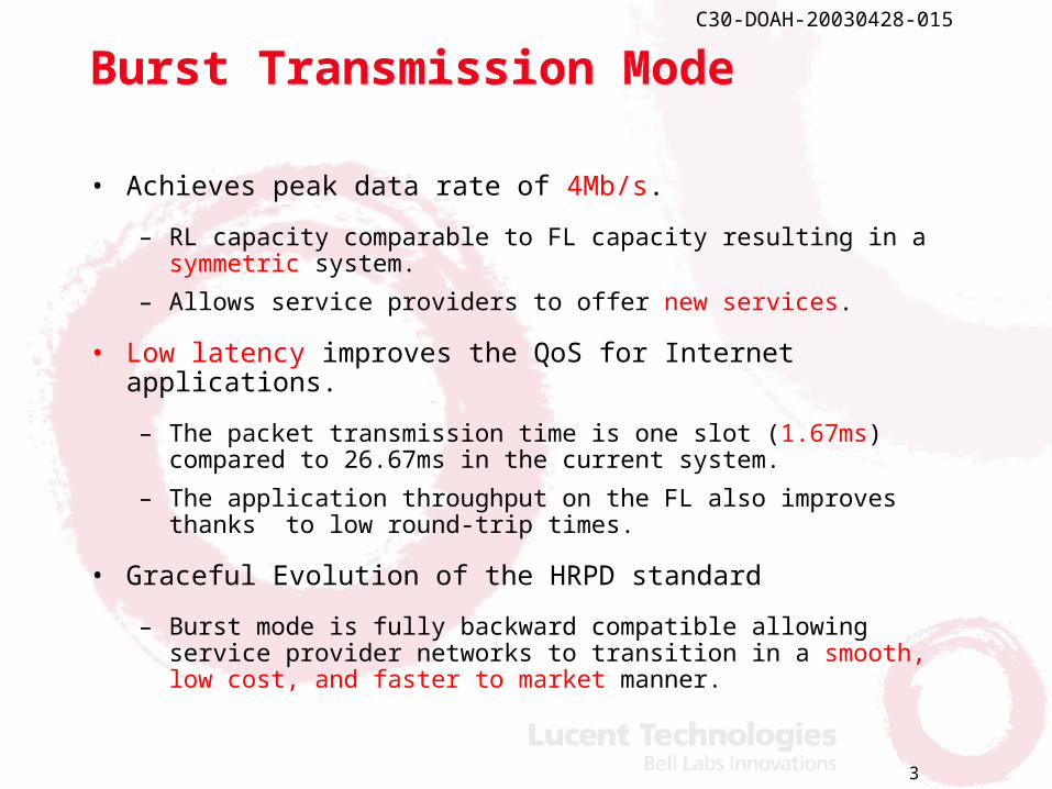
Burst Transmission Mode
• Achieves peak data rate of 4Mb/s.
– RL capacity comparable to FL capacity resulting in a symmetric system.
– Allows service providers to offer new services.
• Low latency improves the QoS for Internet applications.
– The packet transmission time is one slot (1.67ms) compared to 26.67ms in the current system.
– The application throughput on the FL also improves thanks to low round-trip times.
• Graceful Evolution of the HRPD standard
– Burst mode is fully backward compatible allowing service provider networks to transition in a smooth, low cost, and faster to market manner.

4
C30-DOAH-20030428-015
Burst Mode – Key features
• Slot-synchronized slot-orthogonal RL transmissions.
• Very high Rise-over-Thermal (RoT) allowed during high-speed burst transmission
– A single mobile within a sector transmits at very high power
– Highly simplified scheduling and resource allocation:• No need to accurately measure the total received power or Rise-
over-Thermal (RoT) etc.
• Achieves maximum gains from techniques already used on the FL:
– Base station controlled fast scheduling, Hybrid ARQ and adaptive modulation and coding (AMC):
• With burst mode, RL structure and operation become similar to the FL structure and operation.

5
C30-DOAH-20030428-015
Illustration of Burst Mode
RL
B: Burst slotPC: Power controlled slotIoc: Other cell interferenceDRC: Data rate control
PC
B
B
B
PCB
B
B
PC
B
B
BPC
B
B
B
Pilots
DRCs
Autonomous lowrate data frommultiple users
Ioc
N0W
ACKs
High-speeddata
Ioc
N0W
High-speeddata
PILOT
1 2 3 4 5 6 7 8 9 10 11 12 13 14 15 16
26.67ms
RoT during PC slots is controlled (as in the current systems) in order toguarantee sufficient coverage and capacity.
6
C30-DOAH-20030428-015
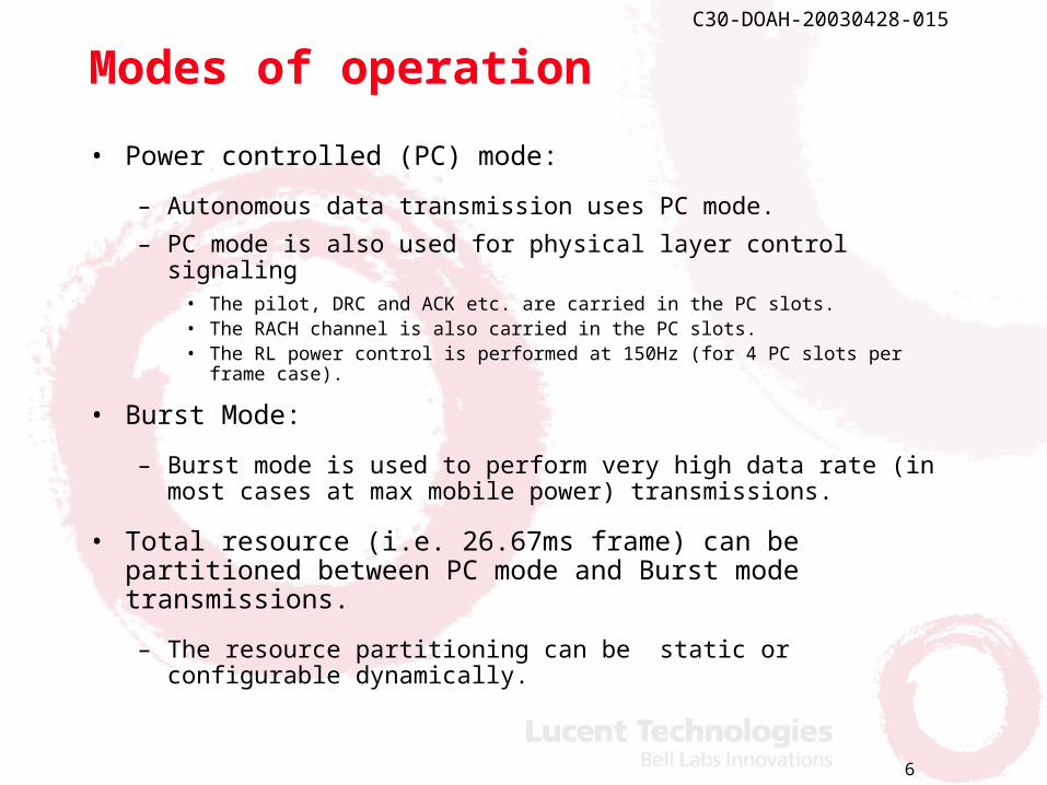
Modes of operation
• Power controlled (PC) mode:
– Autonomous data transmission uses PC mode.
– PC mode is also used for physical layer control signaling• The pilot, DRC and ACK etc. are carried in the PC slots.• The RACH channel is also carried in the PC slots.• The RL power control is performed at 150Hz (for 4 PC slots per frame
case).
• Burst Mode:
– Burst mode is used to perform very high data rate (in most cases at max mobile power) transmissions.
• Total resource (i.e. 26.67ms frame) can be partitioned between PC mode and Burst mode transmissions.
– The resource partitioning can be static or configurable dynamically.

7
C30-DOAH-20030428-015
Burst data rates
• Time multiplexed burst pilot in each slot, serves two purposes;
– channel estimation for demodulation and decoding of the traffic information
– channel quality estimate of the current transmission that allows to select an appropriate rate for any other transmissions to the same user.
Data rate
[Kb/s] Encoder packet
size [bits]
Modulation Coding rate
Number of data chips
Number of pilot chips
T/P ratio [dB]
4003.2 6672 16-QAM 0.834 2000 48 16.20 3686.4 6144 16-QAM 0.768 2000 48 16.20 3072.0 5120 16-QAM 0.640 2000 48 16.20 2457.6 4096 8-PSK 0.688 1984 64 14.91 1843.2 3072 8-PSK 0.525 1952 96 13.08 1228.8 2048 QPSK 0.533 1920 128 11.76 614.4 1024 QPSK 0.276 1856 192 9.85 307.2 512 QPSK 0.276 1856 192 9.85 153.6 256 QPSK 0.276 1856 192 9.85 76.8 128 BPSK 0.276 1856 192 9.85
8
C30-DOAH-20030428-015
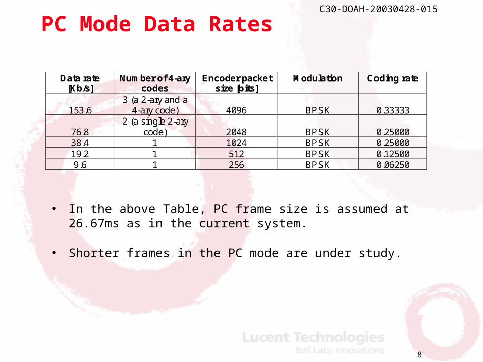
PC Mode Data Rates
• In the above Table, PC frame size is assumed at 26.67ms as in the current system.
• Shorter frames in the PC mode are under study.
Data rate
[Kb/s] Number of 4-ary
codes Encoder packet
size [bits] Modulation Coding rate
153.6 3 (a 2-ary and a
4-ary code) 4096 BPSK 0.33333
76.8 2 (a single 2-ary
code) 2048 BPSK 0.25000 38.4 1 1024 BPSK 0.25000 19.2 1 512 BPSK 0.12500 9.6 1 256 BPSK 0.06250
9
C30-DOAH-20030428-015
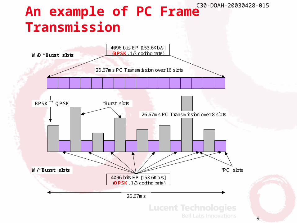
An example of PC Frame Transmission
“Burst” slots
26.67ms
4096 bits EP [153.6Kb/s] (QPSK, 1/3 coding rate)
“PC” slots
4096 bits EP [153.6Kb/s] (BPSK, 1/3 coding rate)
26.67ms PC Transmission over 16 slots
26.67ms PC Transmission over 8 slots
BPSK QPSK
W/O “Burst” slots
W/ “Burst” slots

10
C30-DOAH-20030428-015
AT-AN control signaling (1)
Access Terminal(AT)
RLScheduler
AccessNetwork (AN)
BUFF_INF + R-PICH PWR
Scheduling Grant (Data Rate)
Information used by the scheduler:RL channel qualityAT’s Buffer Status
Reverse link channel quality caneither be derived from:R-PICH power and TPC trackingor Burst pilot received energy
11
C30-DOAH-20030428-015
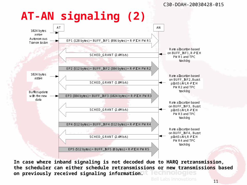
AT-AN signaling (2)AT AN
EP1 (128 bytes) + BUFF_INF1 (896 bytes) + R-PICH PWR1
EP2 (512 bytes) + BUFF_INF2 (384 bytes) + R-PICH PWR2
EP3 (384 bytes) + BUFF_INF3 (1024 bytes) + R-PICH PWR3
EP5 (512 bytes) + BUFF_INF5 (0 bytes) + R-PICH PWR5
EP4 (512 bytes) + BUFF_INF4 (512 bytes) + R-PICH PWR4
1024 bytesarrive
1024 bytesarrive
AutonomousTransmission
Rate allocation basedon BUFF_INF1, R-PICH
PWR1 and TPCtracking
Rate allocation basedon BUFF_INF2, Burstpilot Ec/Nt, R-PICH
PWR2 and TPCtracking
Rate allocation basedon BUFF_INF3, Burst
pilot Ec/Nt, R-PICHPWR3 and TPC
tracking
Rate allocation basedon BUFF_INF4, Burst
pilot Ec/Nt, R-PICHPWR4 and TPC
tracking
SCHED_GRANT (2.4Mb/s)
SCHED_GRANT (1.8Mb/s)
SCHED_GRANT (2.4Mb/s)
SCHED_GRANT (2.4Mb/s)
Buffer updatewith the new
data
In case where inband signaling is not decoded due to HARQ retransmission, the scheduler can either schedule retransmissions or new transmissions based on previously received signaling information.
12
C30-DOAH-20030428-015
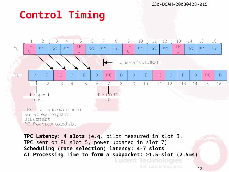
Control Timing
B B PC B B B PC BB B PC B B B PC BRL
TPC
SG SG SGTPC
SG SG SGTPC
SG SG SGTPC
SG SG SG
One-half slot offset
FL
High-speedburst
Pilot, DRCetc.
1 2 3 4 5 6 7 8 9 10 11 12 13 14 15 16
1 2 3 4 5 6 7 8 9 10 11 12 13 14 15 16
TPC: Transmit power controlSG: Scheduling grantB: Burst slotPC: Power controlled slot
TPC Latency: 4 slots (e.g. pilot measured in slot 3,TPC sent on FL slot 5, power updated in slot 7)Scheduling (rate selection) latency: 4-7 slots AT Processing Time to form a subpacket: >1.5-slot (2.5ms)
13
C30-DOAH-20030428-015
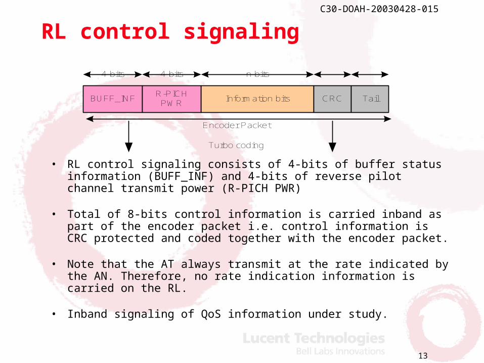
RL control signaling
• RL control signaling consists of 4-bits of buffer status information (BUFF_INF) and 4-bits of reverse pilot channel transmit power (R-PICH PWR)
• Total of 8-bits control information is carried inband as part of the encoder packet i.e. control information is CRC protected and coded together with the encoder packet.
• Note that the AT always transmit at the rate indicated by the AN. Therefore, no rate indication information is carried on the RL.
• Inband signaling of QoS information under study.
Information bitsBUFF_INFR-PICH
PWRCRC Tail
4-bits 4-bits n-bits
Turbo coding
Encoder Packet
14
C30-DOAH-20030428-015
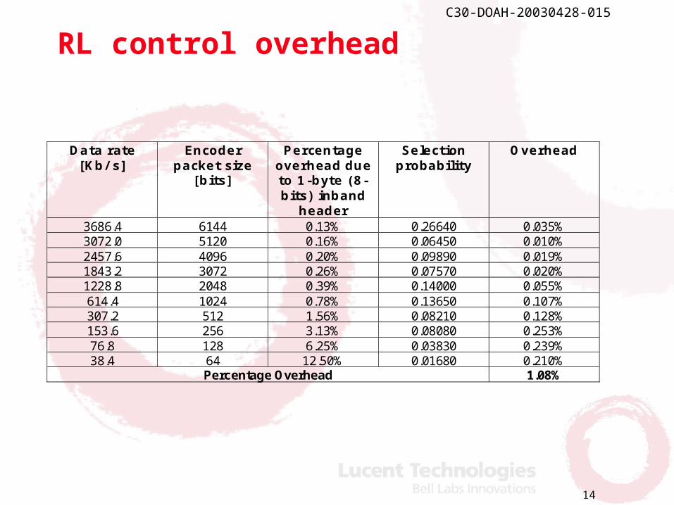
RL control overhead
Data rate [Kb/ s]
Encoder packet size
[bits]
Percentage overhead due to 1-byte (8-bits) inband
header
Selection probability
Overhead
3686.4 6144 0.13% 0.26640 0.035% 3072.0 5120 0.16% 0.06450 0.010% 2457.6 4096 0.20% 0.09890 0.019% 1843.2 3072 0.26% 0.07570 0.020% 1228.8 2048 0.39% 0.14000 0.055% 614.4 1024 0.78% 0.13650 0.107% 307.2 512 1.56% 0.08210 0.128% 153.6 256 3.13% 0.08080 0.253% 76.8 128 6.25% 0.03830 0.239% 38.4 64 12.50% 0.01680 0.210%
Percentage Overhead 1.08%
15
C30-DOAH-20030428-015
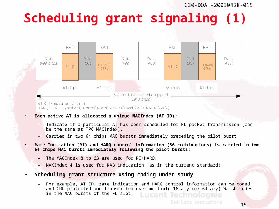
Scheduling grant signaling (1)
• Each active AT is allocated a unique MACIndex (AT ID):
– Indicate if a particular AT has been scheduled for RL packet transmission (can be the same as TPC MACIndex).
– Carried in two 64 chips MAC bursts immediately preceding the pilot burst
• Rate Indication (RI) and HARQ control information (56 combinations) is carried in two 64 chips MAC bursts immediately following the pilot bursts:
– The MACIndex 8 to 63 are used for RI+HARQ.
– MAXIndex 4 is used for RAB indication (as in the current standard)
• Scheduling grant structure using coding under study
– For example, AT ID, rate indication and HARQ control information can be coded and CRC protected and transmitted over multiple 16-ary (or 64-ary) Walsh codes in the MAC bursts of the FL slot.
Data(400 chips)
RAB
AT ID
Pilot(96)
Data(400)
RAB
RI+HARQCTRL
Data(400)
RAB
Pilot(96)
Data(400)
RAB
RI+HARQCTRL
RI: Rate Indication (7 rates)HARQ CTRL: Hybrid ARQ Control (4 ARQ channels and 2 ACK/NACK levels)
64 chips 64 chips 64 chips 64 chips
Slot containing scheduling grant(2048 chips)
AT ID
16
C30-DOAH-20030428-015
Scheduling grant signaling (2)• In variable rate burst mode operation, AT ID length is 128 chips (2 bursts
of 64 chips).
• Autonomous operation not requiring scheduling grants can be allowed for the disadvantaged users.
• Fixed rate operation can also be allowed for disadvantaged users. In this case 256 chips in a slot can be used as AT ID.
• Slots containing TPC bits and scheduling grants are orthogonal in time. New ATs will not look for TPC bit in the slots designated for scheduling grants and vice versa.
• Legacy ATs with TPC MACIndex the same as the new scheduled AT MACIndex or RI+HARQ MACIndex can interpret scheduling grant as TPC bit.
• Since only two TPC MACIndices (AT ID and RI+HARQ control) can be active in a slot containing scheduling grant, this will have negligible impact on power control operation for legacy ATs.
• DRCLock Channel is carried in slots orthogonal to slots carrying scheduling grants.
17
C30-DOAH-20030428-015
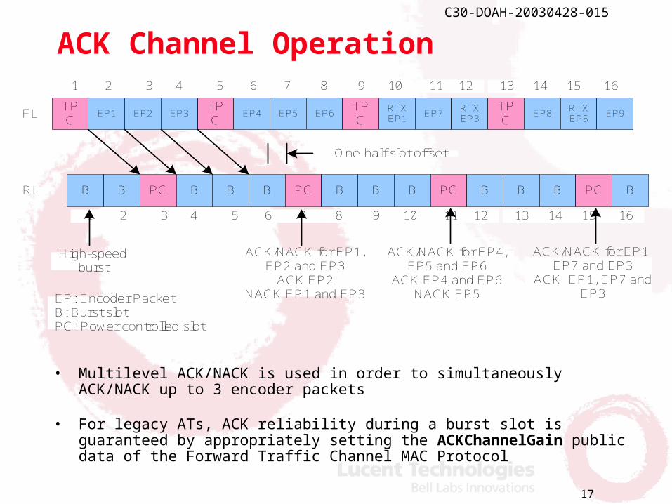
ACK Channel Operation
• Multilevel ACK/NACK is used in order to simultaneously ACK/NACK up to 3 encoder packets
• For legacy ATs, ACK reliability during a burst slot is guaranteed by appropriately setting the ACKChannelGain public data of the Forward Traffic Channel MAC Protocol
B B PC B B B PC BB B PC B B B PC BRL
TPC
EP4 EP5 EP6TPC
RTXEP1
EP7RTXEP3
TPC
EP1 EP2 EP3TPC
EP8RTXEP5
EP9
One-half slot offset
FL
High-speedburst
ACK/NACK for EP1,EP2 and EP3
ACK EP2NACK EP1 and EP3
1 2 3 4 5 6 7 8 9 10 11 12 13 14 15 16
1 2 3 4 5 6 7 8 9 10 11 12 13 14 15 16
EP: Encoder PacketB: Burst slotPC: Power controlled slot
ACK/NACK for EP4,EP5 and EP6
ACK EP4 and EP6NACK EP5
ACK/NACK for EP1,EP7 and EP3
ACK EP1, EP7 andEP3
18
C30-DOAH-20030428-015
Signaling overhead - observations
• Minimum signaling and control overhead in order to support burst mode:
– Approximately 1% RL overhead
– No additional FL overhead (small degradation due to 150Hz RL power control)
• Signaling and control optimized to reduce delays
– Up to date buffer information available at the base station scheduler
• Every encoder packet carries buffer update information
• Backward compatible control structure
– The new and legacy ATs coexist on the same carrier
19
C30-DOAH-20030428-015
Simulation Assumptions
• Inline with 1xEV-DV evaluation methodology
– 3-sector 19-cell, Wrap-around
– Channel mix etc.
• 10 users with Full buffers
• HARQ based on incremental redundancy
– SHO gain not assumed i.e. ACK/NACK from the serving cell only
• HARQ in SHO is understudy
• All users are scheduled in burst mode
– No autonomous transmissions assumed• Simulations results for the hybrid case where some users are
allowed to transmit in the PC mode as well will be provided later on.
20
C30-DOAH-20030428-015
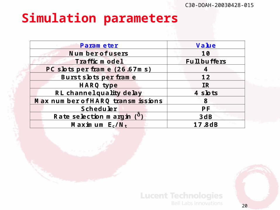
Simulation parameters
Parameter Value Number of users 10
Traffic model Full buffers PC slots per frame (26.67ms) 4
Burst slots per frame 12 HARQ type IR
RL channel quality delay 4 slots Max number of HARQ transmissions 8
Scheduler PF Rate selection margin () 3dB
Maximum Ec/ Nt 17.8dB
21
C30-DOAH-20030428-015
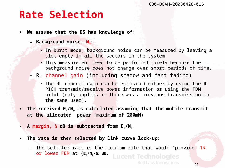
Rate Selection
• We assume that the BS has knowledge of:
– Background noise, N0:
• In burst mode, background noise can be measured by leaving a slot empty in all the sectors in the system.
• This measurement need to be performed rarely because the background noise does not change over short periods of time.
– RL channel gain (including shadow and fast fading)
• The RL channel gain can be estimated either by using the R-PICH transmit/receive power information or using the TDM pilot (only applies if there was a previous transmission to the same user).
• The received Ec/N0 is calculated assuming that the mobile transmit at the allocated power (maximum of 200mW)
• A margin, dB is subtracted from Ec/N0
• The rate is then selected by link curve look-up:
– The selected rate is the maximum rate that would “provide” 1% or lower FER at (Ec/N0-dB.
22
C30-DOAH-20030428-015
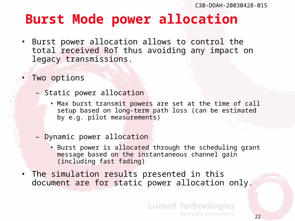
Burst Mode power allocation
• Burst power allocation allows to control the total received RoT thus avoiding any impact on legacy transmissions.
• Two options
– Static power allocation• Max burst transmit powers are set at the time of call setup
based on long-term path loss (can be estimated by e.g. pilot measurements)
– Dynamic power allocation • Burst power is allocated through the scheduling grant message
based on the instantaneous channel gain (including fast fading)
• The simulation results presented in this document are for static power allocation only.
23
C30-DOAH-20030428-015
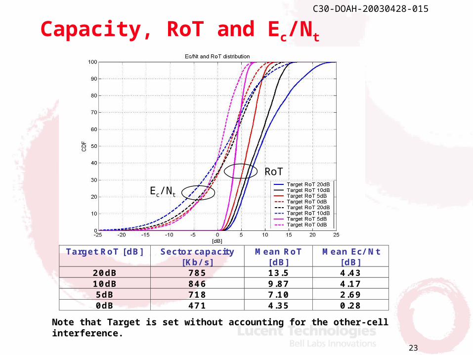
Capacity, RoT and Ec/Nt
Ec/Nt
RoT
Target RoT [dB] Sector capacity [Kb/ s]
Mean RoT [dB]
Mean Ec/ Nt [dB]
20dB 785 13.5 4.43 10dB 846 9.87 4.17 5dB 718 7.10 2.69 0dB 471 4.35 0.28
Note that Target is set without accounting for the other-cell interference.

24
C30-DOAH-20030428-015
MS Transmit PWR CDF
23dBm
25
C30-DOAH-20030428-015
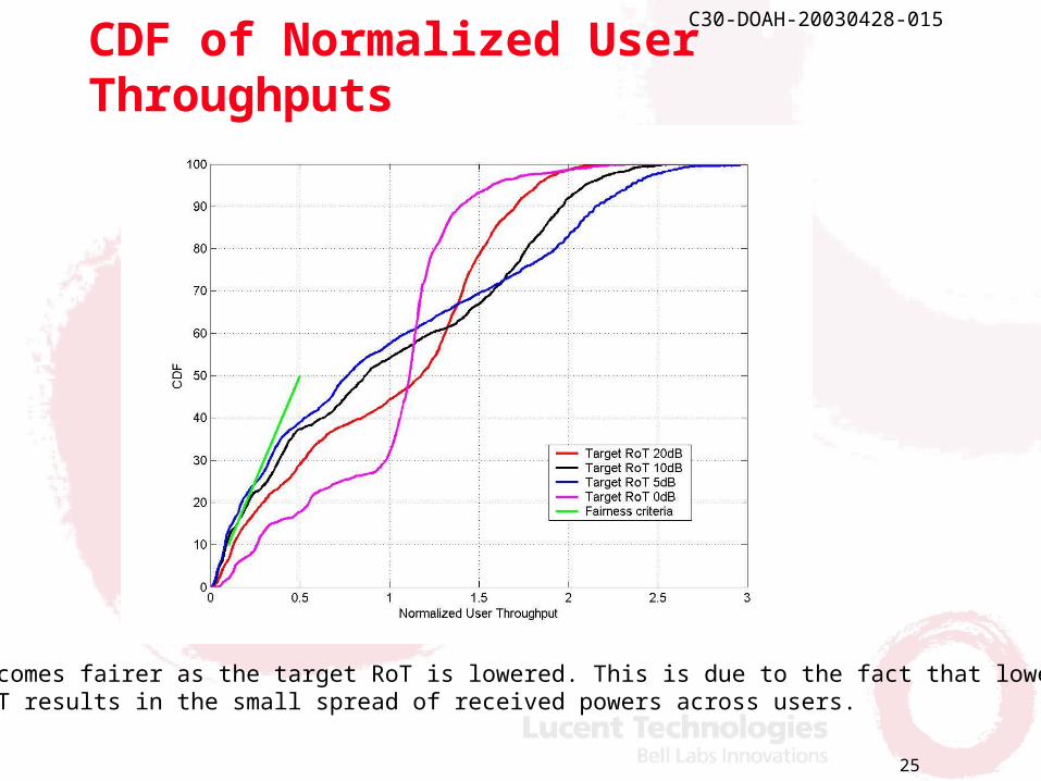
CDF of Normalized User Throughputs
System becomes fairer as the target RoT is lowered. This is due to the fact that loweringtarget RoT results in the small spread of received powers across users.
26
C30-DOAH-20030428-015
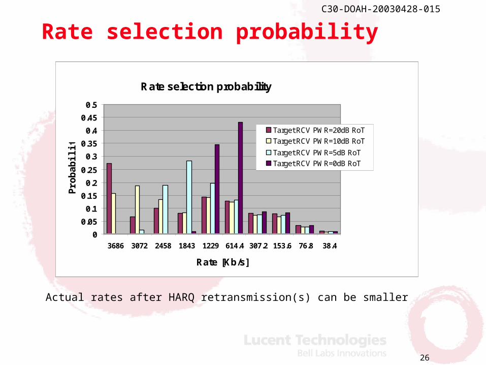
Rate selection probability
Actual rates after HARQ retransmission(s) can be smaller
Rate selection probability
0
0.05
0.1
0.15
0.2
0.25
0.3
0.35
0.4
0.45
0.5
3686 3072 2458 1843 1229 614.4 307.2 153.6 76.8 38.4
Rate [Kb/s]
Pro
ba
bil
ity
Target RCV PWR=20dB RoT
Target RCV PWR=10dB RoT
Target RCV PWR=5dB RoT
Target RCV PWR=0dB RoT
27
C30-DOAH-20030428-015
Backward compatibility
• In the presence of legacy users, burst transmission power can be allocated such that the total RoT does not exceed the specified target
– e.g. RoT should be below 7dB 99% of the time.
• DRC from legacy users can be operated in the Gated mode making sure that the DRC transmission only happen in the PC slots.
– Maximizes the burst mode TDM gain
28
C30-DOAH-20030428-015
Further optimizations
• Burst and control strategy:
– New mobiles are allowed to transmit at a higher RoT even if the slot is used by legacy transmission(s).
– Quality for legacy transmissions is guaranteed by increasing the outer loop PC threshold to compensate for the loss in energy due to higher RoT Burst transmission.
• Interference cancellation
– A single Burst user (strongest and known user) can be detected and cancelled from the overall signal in the same sector.
• Scheduler and rate selection optimization
– For example, rate specific margins
29
C30-DOAH-20030428-015
Summary
• Burst Mode meet and exceed CDG SRD requirements (>2.4 Mb/s peak data rate and >600Kb/s capacity in 1.25MHz bandwidth).
• Burst mode provides significant improvements in RL capacity.
– The RL capacity becomes comparable to FL resulting in a symmetric system.
– Allows service providers to offer new services.
• Burst mode provides a fully backward compatible solution
– New Burst mode and legacy mobiles coexist on the same carrier.