Embed Size (px)
Citation preview
.-
'
1 e
|
l
-
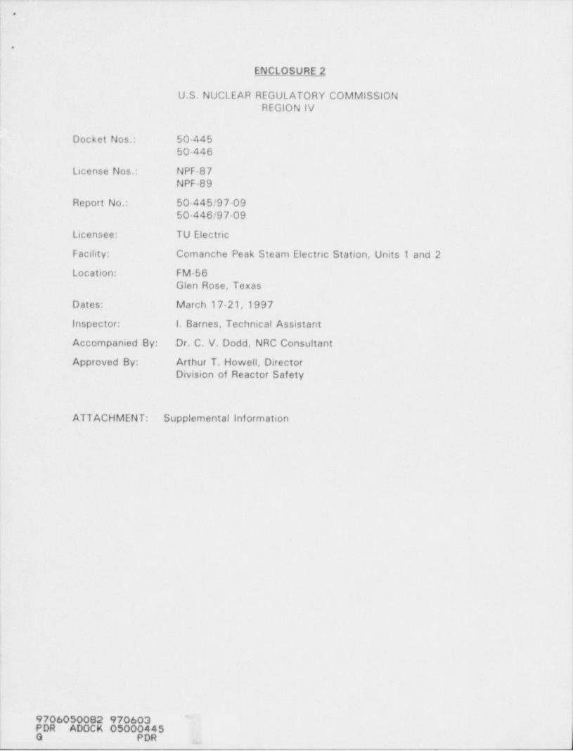
ENCLOSURE 2i'U.S. NUCLEAR REGULATORY COMMISSION
REGION IV
i
Docket Nos. 50-44550-446 i
1
License Nos.. NPF-87 !
NPF-89 )Report No.: 50-445/97 09 I
50-446/97-09
Licensee: TU Electric1
Facility: Comanche Peak Steam Electric Station, Units 1 and 2 !l
Location: FM-56Glen Rose, Texas
Dates: March 17-21,1997
Inspector: 1. Barnes, Technical Assistant
Accompanied By: Dr. C. V. Dodd, NRC Consultant
Approved By: Arthur T. Howell, Director;
Division of Reactor Safety
ATTACHMENT: Supplemental information
|
|
|'9706050082 970603
PDR ADOCK 050004450 PDR ,,
r
! *
.
-2-
!
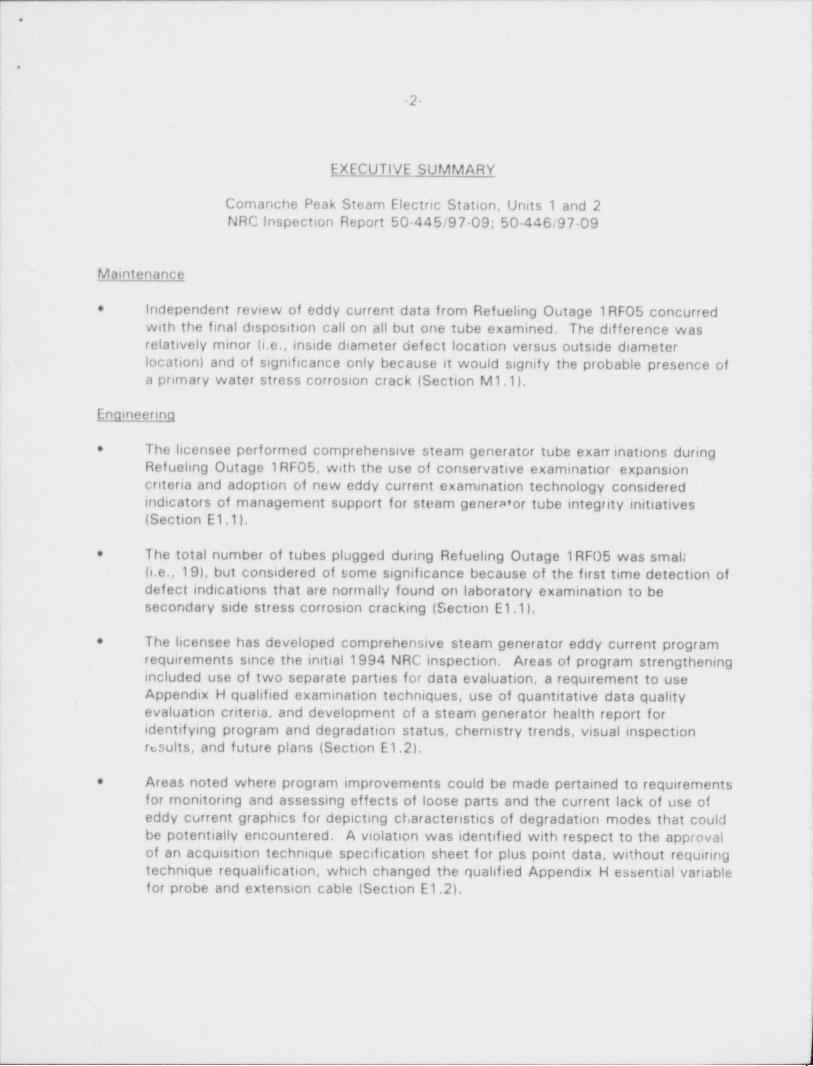
EXECUTIVE SUMMARY
Comanche Peak Steam Electric Station, Units 1 and 2l NRC inspection Report 50-445/97-09; 50-446/97-09
Maintenance
Independent review of eddy current data from Refueling Outage 1RF05 concurred*
with the final disposition call on all but one tube examined. The difference wasrelatively minor (i.e., inside diameter defect location versus outside diameterlocation) and of significance only because it would signify the probable presence ofa primary water stress corrosion crack (Section M1.1).
Enaineerina
The licensee performed comprehensive steam generator tube exarrinations during*
Refueling Outage 1RF05, with the use of conservative examinatior expansioncriteria and adoption of new eddy current examination technology consideredindicators of management support for steam generMor tube. integrity initiatives(Section E1.1).
The total number of tubes plugged during Refueling Outage 1RF05 was small*
(i.e.,19), but considered of some significance because of the first time detection ofdefect indications that are normally found on laboratory examination to besecondary side stress corrosion cracking (Section E1.1).
The licensee has developed comprehensive steam generator eddy current program*
requirements since the initial 1994 NRC inspection. Areas of program strengtheningincluded use of two separate parties for data evaluation, a requirement to useAppendix H qualified examination techniques, use of quantitative data qualityevaluation criteria, and development of a steam generator health report foridentifying program and degradation status, chemistry trends, visual inspectionresults, and future plans (Section E1.2).
Areas noted where program improvements could be made pertained to requirements*
for monitoring and assessing effects of loose parts and the current lack of use ofeddy current graphics for depicting characteristics of degradation modes that couldbe potentially encountered. A violation was identified with respect to the approvalof an acquisition technique specification sheet for plus point data, without requiring
| technique requalification, which changed the qualified Appendix H essential variable' for probe and extension cable (Section E1.2).
)

. _ .-. - .-
.
.
-3-
The programmatic requirement for analysts to be certified as qualified data analysts*
.was considered a program strength. The licensee had compiled an appropriate poolof eddy current test data for verification of individual analyst ability to make correctinterpretations of data (Section E1.3).
The licensee appropriately responded to the results of external assessments of eddy*
current program requirements (Section E1.4).
,
i
s

_ - . . .. _. _ . . _ _ .. . _ _ . - _ _ - . _ _ _ . _ _ _ _ _ . . .__ ._
*
u
| \
I'
-4- )i'
|'
|1
Report Details i
This inspection was performed as a followup to an initial baseline inspection of steamgenerator programs, history, and material condition, which was documented in NRC
' Inspection Report 50-445;-446/94-01. The initialinspection' identified examples of wherethe established program requirements, for examination of steam generator tubing, did notfully reflect applicable industry guidance and generic communications. The currentinspection utilized Inspection Procedure 92903 and technical requirements contained in
! Inspection Procedure 50002.I
Summary of Plant Status !
Units 1 and 2 were at 100 percent power during the inspection period.
II. Maintenance
M1 Conduct of Maintenance
| M1.1 Review of Tube Examination Data1
a. Inspection Scope.
The inspector selected a limited sample of Unit 1 eddy current data from the last : i
refueling outage, Refueling Outage 1RFOS, for independent assessment by the NRC )consultant. Included in the assessment scope were defective calls by the primary 1
and/or secondary analyst which were overruled by the resolution analysts, dataanomalies that were initially identified during Refueling Outage 1RF04 examinations,and Refueling Outage 1RF05 defective calls that were plugged. i
iIb. Observations and Findinas
The NRC consultant reviewed the plus point and pancake coil eddy current data thatwas obtained during Refueling Outage 1RFOS from the following tubes in SteamGenerator 3: Row (R) 2, Column (C) 21; R23, C45; R9, C30; R2, C34; R3 C34; |
| and R2, C35. These tubes were identified as containing circumferential defect! indications by the primary and/or secondary analyst, with the final call by the |
| resolution analysts being no detectable degradation. The NRC consultant did not |
! disagree with any of the calls by the resolution analysts, and noted that the defect |calls by the production analysts appeared to result from the intersection of a non- '
,
j defect signal with the tube expansion transition region.
During the Refueling Outage 1RF04 eddy current examinations in 1995, a number; of tubes were identified which exhibited signal anomalies in the data produced by a j
Zetec Delta probe from the top of the tube sheet region. This type of probe'
4
contained a 0.115-inch pancake coil, an axial sensitive coil, and a circumferential,
.
'
i
.

___ . _ -. . - . - . . - -
I
,l*
I
|-
( .s.1
i
!
sensitive coil. These tubes showed long signals in the axial direction that had" bumps" at regular intervals. The NRC consultant reviewed the 1995 data from thefollowing Steam Generator 2 tubes that exhibited this anomaly: R45,C43;R47, I
C55; R49, C51; and R49, C61. The phase of these signals was observed to not )
rotate like a defect above or below the tube sheet as the frequency was changed.However, the intersection of these signals with the expansion transition region didproduce a signal on some of the frequencies that could be interpreted to represent adefect with an approximate inside diameter location. The licensee concluded in i
1995, after detailed review and performance of supplementary ultrasonicexaminations, that the signal anomalies were not evidence of the presence ofdefects. The NRC consultant reviewed the data produced for the same tubes in the1996 Refueling Outage 1RF05 examinations. These examinations were performedusing a probe containing a plus point coil and two pancake coils. (See Section E1.1below for additional probe information). The signal was noted to be present in thedata from the pancake coils, and greatly reduced in the plus point data ( particularlyaway from the expansion transition region). Figure 1 shows an example of thesignal anomaly as exhibited by the plus point coil. Figure 2 shows the phase for ananomaly at different frequencies, in some instances, a small, low-voltagedefect-like signal could be found on the plus-point channel in this region, but it waswell within the noise. The NRC consultant concurred with the licensee position thatthe available information did not support classification of these signal anomalies asdefects. The inspector considered the only feasible method for determination of thereasons for the anomalies would be removal of a tube sample from a steamgenerator for laboratory examination.
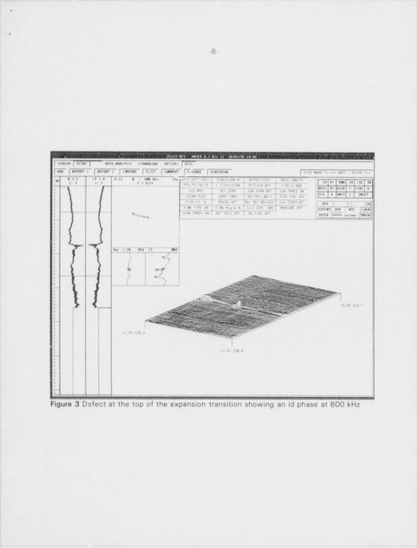
The NRC consultant reviewed the eddy current data from the following tubes, whichhad been called as containing defect indications and subsequently plugged: SteamGenerator 2 - Tubes R23, C44, R43, C47, and R1, C98; Steam Generator 4 - R26,C104 and R34, C98. All of the calls appeared to be correct with one exception.The NRC consultant determined that Tube R34 C98 of Steam Generator 4 appearedto contain an inside diameter axial crack rather than the outside diameter axial crackthat was called. Eddy current information for this defect indication is shown inFigures 3 and 4. There were two axial cracks noted to be present, with one ofthem close to 100 percent through the wall. Most of the data indicated an insidediameter indication, with the 0.080-inch pancake coil further confirming insidediameter cracking by exhibiting a larger signal at a 800 kHz frequency than thatshown at 600 kHz.

+
e
-6-
2 | Luttrnst |ft151 | Stat 14RY | tit %N&t | Stat tuint | u n'.a v w.e .t. * * * un t I * ut r un * * *
1.51 8 1 400 Rhs 3D McT at ste '. Jd 3' J SLAT ated 0 CF f 5t ia l34' th i D 9tl=3 / | Sie il RDW 43 C OL 51C1 PP5: Stu 38/ 33 1 ?!CF5/5CHN Pl ! C H = 0. 040 L I RC *2. sf 06 Ig, ,
247 kftt 5f T _2f B0 SUB SCHN OF F 500 TRhCE OFF
(SLHN PLOT vtRT t tttP OLLf M*l.ee v 11Lk THH 164~ICk CH. 8 R3LfW CFF 'FC* 72' #D=236' CIR STEPsiO*i
[[gyggg |gyg |{I NTE IN
F t *64 f vPE ## F L att Hng l e a Los t D;M. 100 MEH5UHE Of f | gig g igySCAN TRr0 ON SET TPlG OF F fx_C I RC.0f f '$PffD ***** s a/ ses TRAlp
.N
Vpp 67$8 DIMI of
% /
[ ch
\- s
3 *+2.57 131.9
N -
' ~
+4. 92 187. 3
s
O,
1
+ 2. 62 187.1 |
Figure 1 Anomaly at the top of the tube sheet for tube Row 49 Col 51,
1
1

.
.
.
-7-
.
|
i
I
, , . . . . . . . . . . . , , . . . . . . . . . . . . . .-
-
i. .
inni ,m st enont ona | orinnt j vrn ;
i ,,,,,... i ,,,,, , , - . . . p. ,m. rs< ii i i. i-i>.<,--.... . 4. ..,, ,.
-
. , . . . . , . . ,, ,, ,, ,, , , , ,,
, .m . ..,. . ,,,, .
S/. 2 unif B , NL L T,-
>/
[iitarl av,n la pl inv
p a a"n,,, . . i..... .I .,n n>
... .....
..
.
v,ro, ,rr ,r- .r v,rtn ,rn .rf f-
%~.s. % 3, ,
% |
| J '.,
... ., . . . .. .... , ,, ,. . . ,C $ C I
.
9
3
s{.-1
1.x.z. ss1;;; .'', ..,;;;;; ,;;;v., , or or n rs a wrri. m >ii
.
.-
(' / *t 7 M'
r y 9;: ; ; ;' = - - -, s .cw x c n .
-p I
. 1
i{,~
C g Jg ,r, f-
- c
Figure 2 Phase at different frequencies for a anomaly
|,
1
I
l;
!
4 y -a,a,1J , - -w m -m- - = m 4.- ---.-
e
a
| 8
!
l
I|
I
|
|
i
!
| Statte | M fvP | AUTB_RNat fill STament ant ePfitf t ( UtiL
fY | AtFDPI i | 8trott # | (8HPRWE | filif | SMd7 4$Y | MRttuim6 | s e u wwo % ** * Up t f * en tuu = ==83W LP 3 V 4 b) 8 8 688 the its et in/ *, Jdt's M.ML t sceu # W i % i at 31' ubiu lepa/5,
_2; 6 25 C I tilf
g y ,, 34 ggg 9,,,g; fg,16/ 79 i flCh 5s W eme Pl f C*it. e U C I RC +2. 26 y , ,
315 88*9 51 f _2E RO SU6 St rue DF F S28 'hACE ON(5CAN PLOT wtwr (p DE t t h= t ,00 v ilCE foM leg
_ is th (n. 6 RM EH Of f NJe 3h* NGalhr llh STEPulea jg } g. gg
Fl*h IvPE uh F L 44 #as te a Cm l OlN. In MLem Of F jattui nTt nit )t im57eE |otees $18- ' -
ce 5tHN TRAL'n UN sgf Tal6 Wf #M_C I RC J3F F SPf f B t
| _
kf
| -
I tI
|'
>
v., i .T. eini .er,
~
L ,_J
r
_ j Qi
- - - _ ,_A
~ l
~8~
i - -~ ' - *5.67 219.7. -,
f
" '
*l.87 226.2
| *i.91 238.4_.
_
_
- . - - - _- _ _ _ _ _ _ _
Figure 3 Defect at the top of the expansion transition showing an id phase at 600 kHz
i
|
I,
lI
li

e
o
9
. . , o ., s .., ,,. s , ..,,,m,,..
| Mstle j st rur j auf s.,nwat v5:5 timment ent sr fit RL | ul L
| nae | af reet t | af ront t | (entnet | f tist | sumns? | ni na,,( | Maf f al.E j w.a en < t. ..s i,,i t . ni rna se
j, a3v tr I w d el e J Det she )* o f .i ti f.15 " >4 x at t coa as e or e st i . is' wk. L Intes. /52: S 2: 6 C 5 Sif f
_ pp.g fp yg , i r; 3 3,3,,n { P1Trweop L j a( .2. eet,% H m M m n
,[ J i'r Pm I it f 2E PO i sue stah of f suli 'kWE Of F,' '* j '
' " ' ~ *' **
'
L5cy P ct | vtp? ty ' DEL' A. t se y f i ta T** 164 I" ' *I ''''., I*i
_ f!Cs (d. E] *g d8 7 Wa* 6 7' ftc.14' CI A $7EPele' gyg g g g3'u f *PE un }8rm 49 ee H | Con t 04 les ME PSoNt OF F
._ ,_ ,_ _ _ M aN f *M F. On j St i IRif, UP F | Ha_LikC JIP F 5pg g s .~ W |,f..,~1,mik('( sig st uff NTIygMi-
,g- . _ . _ . . _ _ _ _ . . . _ _ _ _ .
t ! !'-
4'
. .n an sn-.
,
/. w,:.c : e.%7am%,
y/ 7
1 . Gcidf9eE53hhh,
m;::%.fMS.yg; Is e ~a
.kA*$ht y:? '&:.,
[' )$'~ Q A
g e;n e w k m; y:t y:r -wm 41%@pansd,.,g p a wd.~ st. ,6s ~ i
wA ws - cs r-
~Y
.
& $ '':h':kh khkj h b$$f $h}5 ''''5fMs
<
[ }' 2. - ' b[ #
?)':hQhW \[_'?'KhSi$RRfNW$5||{}||' N* N #'
f(Qj ' ' *[Qf %Q5-h,'N'& ~ '?{?;hWyhW?j'& & ;: h ik : ~~
.: :h'2m C %.s %f' Ti, 'dO'0'S $h V:W|k|ND'|$ '' - W:'z -
.
"2 M '
Nkh[i' 4.hW'iNUgh(- <sM-
Mc-^
_
NNhkk$h'dh kNh *-
Ny J'%'DN nd3'ijsy3:y N : Se,
.
~
'
._ .s.se tu
g;g%pywy&g- +
- h@SN-Qd;kh
.
O
- 10-
111. Enaineerina
E1 Conduct of Engineering
E1.1 Review of Refuelino Outaae 1RF05 Tube Examination Scope and Results
a. Inspection Scoce (92903)
The inspector reviewed the tube examination scope and methods that were used inRefueling Outage 1RF05 with respect to Technical Specification requirements,industry guidance, and as a result of emerging degradation modes. A review wasalso performed of the tube plugging data for this outage and the reasons for tubeplugging.
b. Observations and Findinas
The inspector was informed that the licensee initially planned a full-length bobbincoil examination of 100 percent of the active tubes in Stearn Generators 1 and 4and 20 percent of the active tubas in Steam Generators 2 and 3. The initial scopeof planned motorized rotating pancake coil examinations (using a probe containing a
,
plus point coil, a 0.115-inch pancake coil, and a 0.080-inch high frequency pancake'
coil) included: (1) 100 percent of the active tubes in Steam Generators 1 and 4 and20 percent of the active tubes in Steam Generators 2 and 3 at the top of the tubei
sheet on the hot-leg side, (2) 20 percent of the expanded B and D baffle plateintersections in the cold-leg preheater in all four steam generators, (3) all bobbin coil ||
identified dents 2 3 volts at the first hot-leg side tube support plate (i.e., H3) and a |
sample of bobbin coilidentified volts 2 3 volts at higher elevation hot-leg side tubesupport plates, and (4) characterizing ambiguous bobbin coil indications. Theadoption of a probe containing a plus point coil, a relatively new eddy currenttechnology, for examination of the hot-leg side expansion transitions, low radius !U-bends, dents, and preheater intersections, was considered both proactive and afurther indicator of management support for steam generator tube integrityinitiatives. The selection of a 0.080-inch high frequency pancake coil was alsoconsidered an excellent decision in that it increased the capability of the probe to |
detect the presence of defects located at the inside diameter of the tube. In! addition, the planned motorized rotating pancake coil scope included an examination
| by a probe containing a plus point coil of 20 percent of the low radius Rows 1 and2 U-bends in all four steam generators.
Upon discovery of a circumferential indication in a tube at the top of the tube sheeton the hot-leg side of Steam Generator 4, which was the first evidence found duringUnit 1 commercial operation of the probable development of a stress corrosioncrack (i.e., a tube sample was not removed to provide laboratory confirmation of thenature of the degradation), the licensee expanded the planned scope of hot-leg topof tube sheet examinations in Steam Generators 2 and 3 from 20 percent to100 percent using the three coil probe referenced above. The planned scope of full-
i
)

_
e
.
-11
length bobbin coil examinations was also expanded to 100 percent of the activetubes in all four steam generators. The inspector viewed the licensee actions asboth conservative and an indicator of management support for steam generator tubeintegrity initiatives.
The licensee plugged a total of 19 tubes during Refueling Outage 1RF05 (SteamGenerator 1, O tubes; Steam Generator 2,11 tubes; Steam Generator 3,2 tubes;and Steam Generator 4,6 tubes). The respective numbers of tubes pluggedbecause of detection of single circumferential tube indications on the hot-legside at the top of tube sheet were nine in Steam Generator 2 and three in SteamGenerator 4. All of these indications were determined to be locaicd ca ihe outsidediameter of the steam generator tubes. The licensee plugged a tote' of three tubesas a result of the detection of axial tube indications, a single indication in SteamGenerato" 2 and single and multiple indications in Steam Generator 4. The SteamGenerator 2 single axial indication and the Steam Generator 4 multiple axialindications were located on the hot-leg side at the top of tube sheet, with theSteam Generator 4 single axial indication present at the H3 (i.e., first) hot-leg sidetube support plate. Two tubes were preventively plugged because dentingrestricted passage of a bobbin coil, one in Steam Generator 2 and one in SteamGenerator 3. Two tubes (one in Steam Generator 3 and one in Steam Generator 4)were plugged as a result of the identification of volumetric indications. Theinspector considered the number of plugged tubes to be small, but of some
| significance because of the first time detection of defect indications that are; normally found on further investigation to be secondar/ side stress corrosion
cracking.
c. Conclusions
The licensee performed comprehensive steam generator eddy current examinationsduring Refueling Outage 1RF05, with the use of conservative examination
,
j expansion criteria and adoption of new eddy current technology considered| indicators of management support for steam generator tube integrity initiatives. TheI total number of tubes plugged during Refueling Outage 1RF05 was small (i.e.,19),
but considered of some significance because of the first time detection of defectindications that are normally found on laboratory examination to be secondary side I
stress corrosion cracking,j
E1.2 Review of Steam Generator Tube Examination Proaram Reauirements ji
a. Inspection Scope (92903)1
1
The inspector compared the steam generator eddy current examination program |
requirements for Refueling Outage 1RF05 against regulatory requirements, industryguidelines and qualification criteria, and specific commitments made in response toGeneric Letter 95-03, "Circumferential Cracking of Steam Generator Tubes." |
r
|*1:
.
( - 12-
I
b. Observations and Findinns
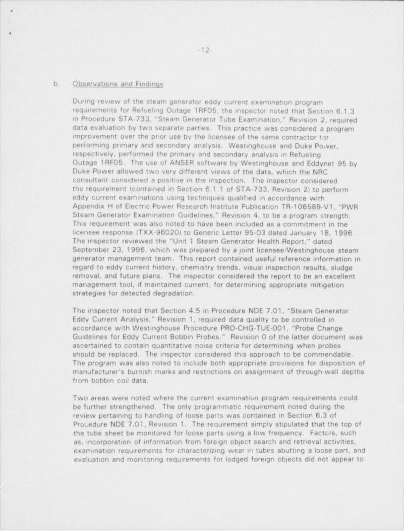
During review of the steam generator eddy current examination programrequirements for Refueling Outage 1RF05, the inspector noted that Section 6.1.3
| in Procedure STA-733, " Steam Generator Tube Examination," Revision 2, required'
data evaluation by two separate parties. This practice was considered a programimprovement over the prior use by the licensee of the same contractor forperforming primary and secondary analysis. Westinghouse and Duke Power,respectively, performed the primary and secondary analysis in RefuelingOutage 1RF05. The use of ANSER software by Westinghouse and Eddynet 95 byDuke Power allowed two very different views of the data, which the NRCconsultant considered a positive in the inspection. The inspector consideredthe requirement (contained in Section 6.1.1 of STA-733, Revision 2) to performeddy current examinations using techniques qualified in accordance withAppendix H of Electric Power Research Institute Publication TR-106589-V1, "PWRSteam Generator Examination Guidelines," Revision 4, to be a program strength.This requirement was also noted to have been included as a commitment in the
; licensee response (TXX-96020) to Generic Letter 95-03 dated January 18,1996.The inspector reviewed the " Unit 1 Steam Generator Health Report," datedSeptember 23,1996, which was prepared by a joint licensee / Westinghouse steamgenerator management team. This report contained useful reference information in
i regard to eddy current history, chemistry trends, visual inspection results, sludgeremoval, and future plans. The inspector considered the report to be an excellentmanagernent tool, if maintained current, for determining appropriate mitigation
;
strategies for detected degradation.
The inspector noted that Section 4.5 in Procedure NDE 7.01, " Steam GeneratorEddy Current Analysis," Revision 1, required data quality to be controlled inaccordance with Westinghouse Procedure PRO-CHG-TUE-001, " Probe ChangeGuidelines for Eddy Current Bobbin Probes." Revision 0 of the latter document wasascertained to contain quantitative noise criteria for determining when probesshould be replaced. The inspector considered this approach to be commendable.The program was also noted to include both appropriate provisions for disposition ofmanuf acturer's burnish marks and restrictions on assignment of through-wall depths
i from bobbin coil data.1
Two areas were noted where the current examination program requirements could' be further strengthened. The only programmatic requirement noted during the
review pertaining to handling of loose parts was contained in Section 6.3 ofProcedure NDE 7.01, Revision 1. The requirement simply stipulated that the top ofthe tube sheet be monitored for loose parts using a low frequency. Factcrs, suchas, incorporation of information from foreign object search and retrieval activities,examination requirements for characterizing wear in tubes abutting a loose part, andevaluation and monitoring requirements for lodged foreign objects did not appear to
:
i
!
!
I

o
.
-13-
be addressed. The other area pertained to the current absence of applicable eddycurrent graphics (in Procedure NDE 7.01, Revision 1, or a training procedure foranalysts) depicting degradation that could be encountered at Comanche Peak SteamElectric Station. Licensee personnel indicated they were working on incorporatingsuitable graphics.
The inspector t erified that the eddy current contractor responsible for dataacquisition and nrimary analysis, Westinghouse Nuclear Services Division, hadprepared an Acq iisition Technique Specification Sheet (ACTS) and AnalysisTechnique Specification Sheet (ANTS) for each of the eddy current techniquesutilized in Refueling Outage 1RF05. These documents, which are required byAppendix H (Performance Demonstration for Eddy Current Examination) of ElectricPower Research Institute Publication TR-106589-V1, Revision 4, define theAppendix H qualified parameter values and ranges. Changes to the qualifiedparameters (i.e., essential variables) require requalification of the technique.Approval signatures from licensee personnel were noted on each of the ACTS(TBX 01-196, Revision 2; TBX-02-196, Revision 2; and TBX-03-196, Revision 2) !and ANTS ( ANTS 001, Revision 3; ANTS 002, Revision 2; and ANTS 003, I
Revision 3) documents.'
The inspector requested to see the Westinghouse Appendix H qualification |information that was applicable to acquisition of plus point data from the tube ]expansion transitions at the top of the_ tube sheet. This request was made as a '
result of the observation that the applicable ACTS sheet for this examination,TBX-02-196, specified the use of Type RG 174/U or equivalent extension cablerather than the low capacitance extension cable (i.e., Zetec low loss) that theinspector had previously seen used at other facilities for examinations of this type.The inspector had previously ascertained that Type RG174/U cable has an i
approximate capacitance of 26 picofarads/ foot versus approximately 16 picofarads/foot for a low loss cable. Licensee personnel obtained the following informationfrom Westinghouse: (a) the original Electric Power Research Institute Appendix Hqualification for the plus point coil utilized a 50-foot long Zetec high performanceprobe cable and a 50-foot long 7.etec low loss extension cable; and (b) theWestinghouse equivalent qualification specified a 50-foot length of Zetec highperformance probe cable, with either a 100-foot long Zetec low loss extensin, cebieor a 110-foot long Westinghouse cable. The inspector was informed thet tae latterextension cable was a type that had a modified capacitance. The inspector notedthat ACTS TBX-02-196, Revision 2, stipulated the use of a 83-foot maximum lengthof Type RG 174/U (or equivalent) probe cable and a 110-foot maximum length ofType RG 174/U (or equivalent) extension cable,
i
l
Section H.2.1.1 of Appendix H of Electric Power Research InstitutePublication TR-106589-V1, Revision 4, identifies that probe and extensioncable type and length are an esscntial variable. Section H.3.3 of this documentrequires requalification of an acquisition technique if a change in acquisition
| technique causes an essential variable to exceed the qualified range. The cable|
|

*
J
.
- 14-
essential variable change introduced by ACTS TBX-02-196, without performing arequalification of the acquisition technique, is a violation of Criterion IXof Appendix B to 10 CFR Part 50 (50-445/9709-01). The inspector was informedby licensee personnel that their review of this issue (resulting from theinspector's questions) determined that the actual technique used during RefuelingOutage 1RF05 for acquisition of plus point data did not comply with the probe andextension cable requirements of the applicable ACTS TBX-02-196. Actualacquisition was found to have used an 83-foot long Zetec high performance probecable and a 50-foot long Zetec low loss extension cable. This technique, althoughcontrary to the governing ACTS TBX-02-196, was very close to the original ElectricPower Research Institute qualification use of a 50 foot Zetec high performanceprobe cable and 50-foot Zetec low loss extension cable. The inspector concludedthat use of an additional 33 feet of Zetec high performance probe cable, to thatused in the Electric Power Research Institute qualification, should have nodiscernible effect on data quality.
c. Conclusions
The licensee has developed comprehensive steam generator eddy current programrequirements since the initial 1994 NRC inspection. Significant areas of programstrengthening included use of two separate parties for data evaluation, arequirement to use Appendix H qualified examination techniques, use of quantitativedata quality evaluation criteria, and development of a steam generator health reportfor identifying program and degradation status, chemistry trends, visual inspectionresults, and future plans. Areas noted where program improvements could be madepertained to requirements for monitoring and assessing effects of loose parts andthe current lack of use of eddy current graphics for depicting characteristics ofdegradation modes that could be potentially encountered. A violation was identifiedwith respect to the approval of an acquisition technique specification sheet for pluspoint data, without requiring technique requalification, which changed the qualified
| Appendix H essential variable for probe and extension cable.
| E1.3 Reouirements for Trainina and Testina of Data Analysts
i
a. Inspection Scope (92903)
;
! The inspector reviewed the training and testing requirements for data analysts that| were established for Refueling Outage 1RF05.
b. Observations and Findinas.
The inspector ascertained that Procedure NDE 7.03, Revision 1, required that dataanalysts be certified as qualified data analysts in accordance with Appendix G ofElectric Power Research Institute TR-106589-V1, Revision 4, be certified to at leastLevel llA in accordance with American Society of Nondestructive TestingRecommended Practice SNT-TC-1 A, and must successfully pass a site-specific

.
|.
-15-
performance demonstration test prior to analyzing any data. The inspectorsconsidered the requirement for analysts to be certified as qualified data analysts tobe a program strength. The inspector verified that all analysts had successfullypassed the site-specific performance demonstration test and that the pool of eddycurrent test data included an appropriate scope of eddy current probes (i.e., bobbincoil, rotating pancake coil, and plus point coil) and tube degradation modes andlocations (i.e., no detectable degradation, outside diameter stress corrosioncracking - freespan, top of tube sheet, and tube support plate; inside diameterstress corrosion cracking - tube support plate; and wear at anti-vibration bars).
c. Conclusions
The programmatic requirement for analysts to be certified as qualified data analystswas considered a program strength. The licensee had compiled an appropriate poolof eddy current test data for verification of individual analyst ability to make correctinterpretations of data.
|
!E7 Ouality Assurance in Engineering Activities
E7.1 External Assessment of Licensee Eddy Current Examination Proaram
a. Inspection Scope (92903)
The inspector compared the results of 1996 external assessments of the licensee'seddy current examination program by a peer utility and an industry group againstthe current eddy current examination program content.
b. Observations and Findinas
The licensee was noted to have revised program requirements to appropriatelyaddress all substantive comments.
c. Conclusions
The licensee appropriately responded to the results of external assessments of eddycurrent program requirements.
V. Manaaement Meetinas
X1 Exit Meeting Summary
The inspector presented the inspection results to members of licensee management at theconclusion of the inspection on March 21,1997. The licensee acknowledged the findingspresented. No proprietary information was identified.

i
'
e
1,
''ATTACHMENT!
SUPPLEMENTAL INFORMATIONl
PARTIAL LIST OF PERSONS CONTACTED l! 5
1!
Licensee |
IJ. Barker, Engineering Overview Manager |O. Bhatty, Licensing Engineer, Regulatory Affairs !T. Broughton, Operations Work Control !
T. Daskam, Nuclear Overview Department |E. Dyas, Nuclear Overview Department
,
D. Goodwin, Operations Support Manager |T. Hope, Regulatory Compliance Manager i
J. Hoss, Senior Engineer, Engineering Programs iJ. Kelley, Vice President, Nuclear EngineeringF. Madden, Engineering Technical Support Manager ]B. Mays, Engineering Programs Supervisor |
'D Snow, Licensing Engineer, Regulatory AffairsM. Sunseri, Nuclear Training ManagerS. Swilley, Senior Engineer, Engineering ProgramsC. Terry, Group Vice President, Nuclear OperationR.Theimer, Chemistry Manager i
R. Walker, Regulatory Aff airs Manageri
Hartford Steam Boiler Insoection and Insurance Comoany I
J. Hair, Authorized Nuclear Inservice Inspector )
Westinnhouse
H. GutzmanD. ObenazuA. Sagar
NRC
H. Freeman, Resident inspectorV. Ordaz, Resident inspector
i'
INSPECTION PROCEDURES USED
IP 50002 Steam GeneratorsIP 92903 Followup <
l
i
F( t|'
o
i -2- ,
,
ITEMS OPENED
Opened
|
50-445/9709-01 VIO Failure to follow procedure (Section E1.2)
LIGT OF DOCUMENTS REVIEWED
Procedures / Documents
STA-733, " Steam Generator Tube Examination," Revision 2, and Procedure ChangeNotices STA-733 R2-1 through 5
NDE 7.01, " Steam Generator Eddy Current Analysis," Revision 1
" Unit 1 Steam Generator Health Report," dated September 23,1996
CLI-704, " Determination of Primary to Secondary Leakrate," Revision 4
EPRI TR-106589-V1, "PWR Steam Generator Examination Guidelines," Volume 1
PRO-CHG-TUE-001, " Probe Change Guidelines for Eddy Current Bobbin Probes,".
Revision 0 (Westinghouse Procedure) |
I
Unit 1, Fifth Refueling Outage, Steam Generator Inservice Inspection Tube Plugging SpecialReport, dated January 16,1997
Acquisition Technique Specification Sheet TBX-01-196, Revision 2!
Acquisition Technique Specification Sheet TBX-02-196, Revision 2 1
Acquisition Technique Specification Sheet TBX-03-196, Revision 2
Analysis Technique Specification Sheet ANTS 001, Revision '3
Analysis Technique Specification Sheet ANTS 002, Revision 2
Analysis Technique Specification Sheet ANTS 003, Revision 3|
|
1
l
!
!)