Embed Size (px)
Citation preview
R
P2L97Pentium® II Motherboard
USER’S MANUAL
ASUS P2L97 User’s Manual2
USER'S NOTICE
Product Name: ASUS P2L97Manual Revision: 2.05 E266Release Date: October 1998
No part of this manual, including the products and software described in it, may be repro-duced, transmitted, transcribed, stored in a retrieval system, or translated into any language inany form or by any means, except documentation kept by the purchaser for backup purposes,without the express written permission of ASUSTeK COMPUTER INC. (“ASUS”).
ASUS PROVIDES THIS MANUAL “AS IS” WITHOUT WARRANTY OF ANY KIND,EITHER EXPRESS OR IMPLIED, INCLUDING BUT NOT LIMITED TO THE IMPLIEDWARRANTIES OR CONDITIONS OF MERCHANTABILITY OR FITNESS FOR A PAR-TICULAR PURPOSE. IN NO EVENT SHALL ASUS, ITS DIRECTORS, OFFICERS,EMPLOYEES OR AGENTS BE LIABLE FOR ANY INDIRECT, SPECIAL, INCIDEN-TAL, OR CONSEQUENTIAL DAMAGES (INCLUDING DAMAGES FOR LOSS OFPROFITS, LOSS OF BUSINESS, LOSS OF USE OR DATA, INTERRUPTION OF BUSI-NESS AND THE LIKE), EVEN IF ASUS HAS BEEN ADVISED OF THE POSSIBILITYOF SUCH DAMAGES ARISING FROM ANY DEFECT OR ERROR IN THIS MANUALOR PRODUCT.
Product warranty or service will not be extended if: (1) the product is repaired, modified oraltered, unless such repair, modification of alteration is authorized in writing by ASUS; or (2)the serial number of the product is defaced or missing.
Products and corporate names appearing in this manual may or may not be registered trade-marks or copyrights of their respective companies, and are used only for identification orexplanation and to the owners’ benefit, without intent to infringe.
• Intel, LANDesk, and Pentium are registered trademarks of Intel Corporation.• IBM and OS/2 are registered trademarks of International Business Machines.• Symbios is a registered trademark of Symbios Logic Corporation.• Windows and MS-DOS are registered trademarks of Microsoft Corporation.• Sound Blaster AWE32 and SB16 are trademarks of Creative Technology Ltd.• Adobe and Acrobat are registered trademarks of Adobe Systems Incorporated.
The product name and revision number are both printed on the product itself. Manual revi-sions are released for each product design represented by the digit before and after the periodof the manual revision number. Manual updates are represented by the third digit in the manualrevision number.
For previous or updated manuals, BIOS, drivers, or product release information, contact ASUSat http://www.asus.com.tw or through any of the means indicated on the following page.
SPECIFICATIONS AND INFORMATION CONTAINED IN THIS MANUAL ARE FUR-NISHED FOR INFORMATIONAL USE ONLY, AND ARE SUBJECT TO CHANGE ATANY TIME WITHOUT NOTICE, AND SHOULD NOT BE CONSTRUED AS A COM-MITMENT BY ASUS. ASUS ASSUMES NO RESPONSIBILITY OR LIABILITY FORANY ERRORS OR INACCURACIES THAT MAY APPEAR IN THIS MANUAL, INCLUD-ING THE PRODUCTS AND SOFTWARE DESCRIBED IN IT.
Copyright © 1998 ASUSTeK COMPUTER INC. All Rights Reserved.
ASUS P2L97 User’s Manual 3
ASUS CONTACT INFORMATIONASUSTeK COMPUTER INC.MarketingAddress: 150 Li-Te Road, Peitou, Taipei, Taiwan 112Telephone: +886-2-2894-3447Fax: +886-2-2894-3449Email: [email protected]
Technical SupportFax: +886-2-2895-9254BBS: +886-2-2896-4667Email: [email protected]: www.asus.com.twFTP: ftp.asus.com.tw/pub/ASUS
ASUS COMPUTER INTERNATIONALMarketingAddress: 6737 Mowry Avenue, Mowry Business Center, Building 2
Newark, CA 94560, USAFax: +1-510-608-4555Email: [email protected]
Technical SupportFax: +1-510-608-4555BBS: +1-510-739-3774Email: [email protected]: www.asus.comFTP: ftp.asus.com.tw/pub/ASUS
ASUS COMPUTER GmbHMarketingAddress: Harkort Str. 25, 40880 Ratingen, BRD, GermanyTelephone: 49-2102-445011Fax: 49-2102-442066Email: [email protected]
Technical SupportHotline: 49-2102-499712BBS: 49-2102-448690Email: [email protected]: www.asuscom.deFTP: ftp.asuscom.de/pub/ASUSCOM
ASUS P2L97 User’s Manual4
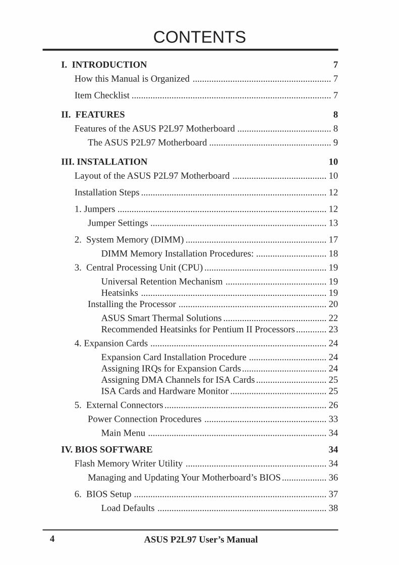
CONTENTS
I. INTRODUCTION 7
How this Manual is Organized ........................................................... 7
Item Checklist ..................................................................................... 7
II. FEATURES 8
Features of the ASUS P2L97 Motherboard ........................................ 8
The ASUS P2L97 Motherboard .................................................... 9
III. INSTALLATION 10
Layout of the ASUS P2L97 Motherboard ........................................ 10
Installation Steps ............................................................................... 12
1. Jumpers ......................................................................................... 12
Jumper Settings ........................................................................... 13
2. System Memory (DIMM) ............................................................ 17
DIMM Memory Installation Procedures: .............................. 18
3. Central Processing Unit (CPU) .................................................... 19
Universal Retention Mechanism ........................................... 19Heatsinks ............................................................................... 19
Installing the Processor ............................................................... 20
ASUS Smart Thermal Solutions ............................................ 22Recommended Heatsinks for Pentium II Processors............. 23
4. Expansion Cards ........................................................................... 24
Expansion Card Installation Procedure ................................. 24Assigning IRQs for Expansion Cards.................................... 24Assigning DMA Channels for ISA Cards .............................. 25ISA Cards and Hardware Monitor ......................................... 25
5. External Connectors ..................................................................... 26
Power Connection Procedures .................................................... 33
Main Menu ............................................................................ 34
IV. BIOS SOFTWARE 34
Flash Memory Writer Utility ............................................................ 34
Managing and Updating Your Motherboard’s BIOS................... 36
6. BIOS Setup .................................................................................. 37
Load Defaults ........................................................................ 38
ASUS P2L97 User’s Manual 5
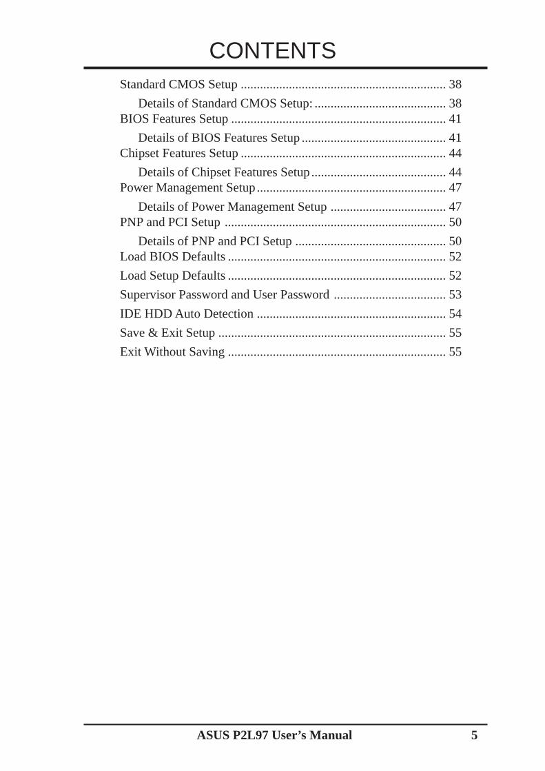
CONTENTSStandard CMOS Setup ................................................................ 38
Details of Standard CMOS Setup: ......................................... 38BIOS Features Setup ................................................................... 41
Details of BIOS Features Setup ............................................. 41Chipset Features Setup ................................................................ 44
Details of Chipset Features Setup.......................................... 44Power Management Setup........................................................... 47
Details of Power Management Setup .................................... 47PNP and PCI Setup ..................................................................... 50
Details of PNP and PCI Setup ............................................... 50Load BIOS Defaults .................................................................... 52
Load Setup Defaults .................................................................... 52
Supervisor Password and User Password ................................... 53
IDE HDD Auto Detection ........................................................... 54
Save & Exit Setup ....................................................................... 55
Exit Without Saving .................................................................... 55
ASUS P2L97 User’s Manual6
FCC & DOC COMPLIANCEFederal Communications Commission StatementThis device complies with FCC Rules Part 15. Operation is subject to the followingtwo conditions:
• This device may not cause harmful interference, and• This device must accept any interference received, including interference that
may cause undesired operation.
This equipment has been tested and found to comply with the limits for a Class Bdigital device, pursuant to Part 15 of the FCC Rules. These limits are designed toprovide reasonable protection against harmful interference in a residential installa-tion. This equipment generates, uses and can radiate radio frequency energy and, ifnot installed and used in accordance with manufacturer's instructions, may causeharmful interference to radio communications. However, there is no guarantee thatinterference will not occur in a particular installation. If this equipment does causeharmful interference to radio or television reception, which can be determined byturning the equipment off and on, the user is encouraged to try to correct the inter-ference by one or more of the following measures:
• Re-orient or relocate the receiving antenna.• Increase the separation between the equipment and receiver.• Connect the equipment to an outlet on a circuit different from that to which
the receiver is connected.• Consult the dealer or an experienced radio/TV technician for help.
WARNING! The use of shielded cables for connection of the monitor to thegraphics card is required to assure compliance with FCC regulations. Changesor modifications to this unit not expressly approved by the party responsible forcompliance could void the user's authority to operate this equipment.
Canadian Department of Communications StatementThis digital apparatus does not exceed the Class B limits for radio noise emissionsfrom digital apparatus set out in the Radio Interference Regulations of the Cana-dian Department of Communications.
ASUS P2L97 User’s Manual 7
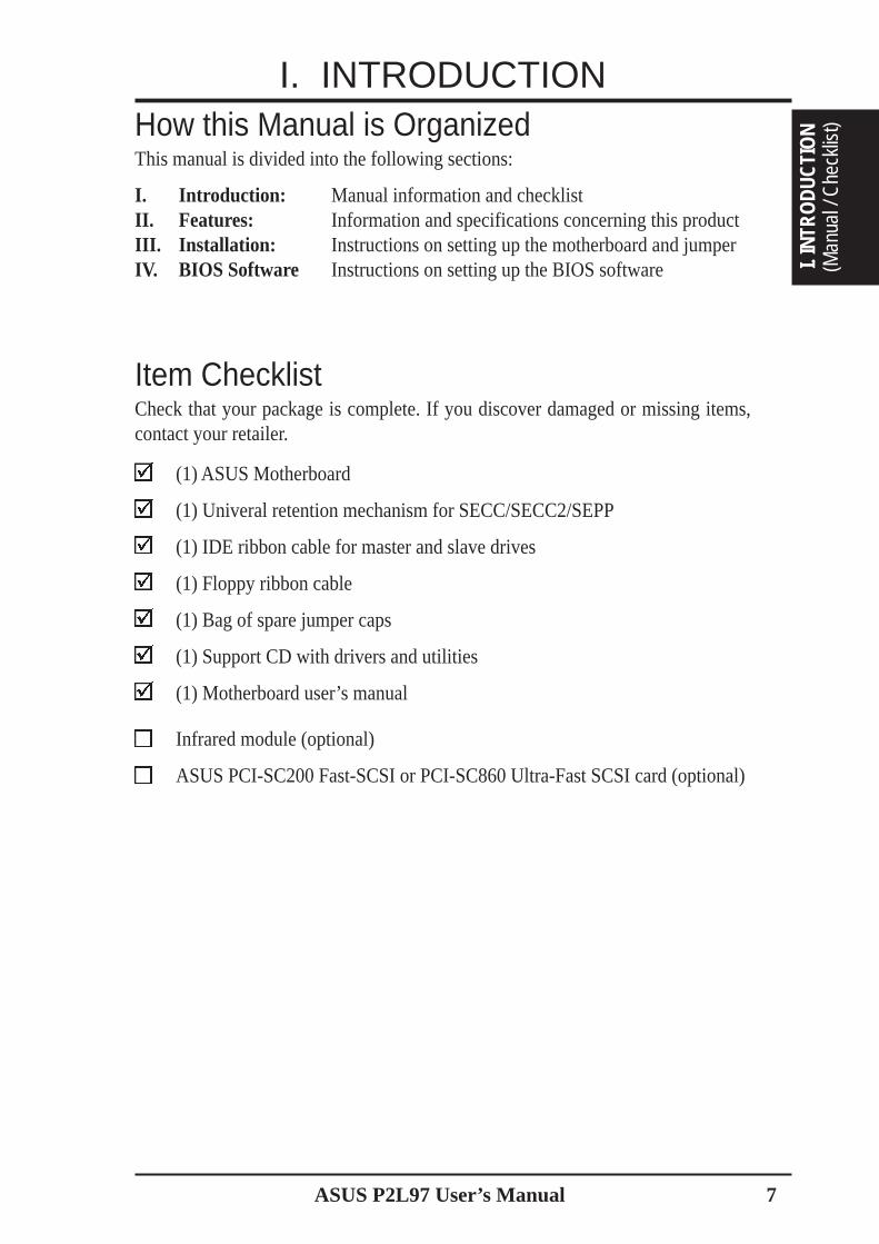
How this Manual is OrganizedThis manual is divided into the following sections:
I. Introduction: Manual information and checklistII. Features: Information and specifications concerning this productIII. Installation: Instructions on setting up the motherboard and jumperIV. BIOS Software Instructions on setting up the BIOS software
Item ChecklistCheck that your package is complete. If you discover damaged or missing items,contact your retailer.
(1) ASUS Motherboard
(1) Univeral retention mechanism for SECC/SECC2/SEPP
(1) IDE ribbon cable for master and slave drives
(1) Floppy ribbon cable
(1) Bag of spare jumper caps
(1) Support CD with drivers and utilities
(1) Motherboard user’s manual
Infrared module (optional)
ASUS PCI-SC200 Fast-SCSI or PCI-SC860 Ultra-Fast SCSI card (optional)
I. INTRODUCTION
I. IN
TRO
DUCT
ION
(Man
ual /
Che
cklis
t)
8 ASUS P2L97 User’s Manual
Features of the ASUS P2L97 MotherboardThe ASUS P2L97 is carefully designed for the demanding PC user who wants manyfeatures processed by the fastest CPU.• Versatile Processor Support: Intel Pentium® II (233MHz–333MHz) processor.• Intel Chipset: Features Intel’s 440LX AGPset with I/O subsystems.• Multi-Cache: Supports processors with Pipelined Burst Level 2 cache.• Versatile Memory Support: Equipped with three DIMM sockets to support (8,
16, 32, 64, or 128MB) 168-pin SDRAM/EDO memory modules up to 384MB.• AGP: Supports Accelerated Graphics Port cards for high performance, compo-
nent level interconnect targeted at 3D graphical display applications.• PCI & ISA Expansion Slots: Provides four 32-bit PCI, one 16-bit ISA, and one
ISA/PCI shared slot.• Enhanced ACPI & Anti-Boot Virus BIOS: Programmable BIOS (Flash EEPROM),
offering enhanced ACPI for Windows 98 compatibility, built-in hardware-basedvirus protection, and autodetection of most devices for virtually automatic setup.
• Thermal Sensor Connector with Optional Sensor: Accurately detects the CPUtemperature of processors with the ASUS Smart Fan or the Intel boxed proces-sor heatsink with fan when connected to an ASUS P2T-Cable.
• Keyboard Power (Wake) Up: Allows the computer to be powered on by press-ing any key on the keyboard.
• Intelligence: Supports Fan Status Monitoring and Alarm, Temperature Moni-toring and Alert, Voltage Monitoring and Alert, System Resources Alert, andVirus Write Protection through the optional onboard LM78 Hardware Monitorand Intel® LANDesk Client Manager (LDCM) software.
• Ultra DMA/33 BM IDE/Floppy: Comes with an onboard PCI Bus Master IDEcontroller with two connectors that supports four IDE devices in two channels, sup-ports Ultra DMA/33, PIO Modes 3 and 4 and Bus Master IDE DMA Mode 2, andsupports Enhanced IDE devices such as Tape Backup, CD-ROM and LS-120 drives.
• Universal Retention Mechanism: Supports a Pentium® II processor packagedin Single Edge Contact Cartridge (SECC/SECC2) or a CeleronTM processor pack-aged in a Single Edge Processor Package (SEPP).
• Wake-On-LAN Connector: Supports Wake-On-LAN activity through an op-tional ASUS PCI-L101 Fast Ethernet card.
• Easy Installation: Equipped with BIOS that supports auto detection of harddrives, PS/2 mouse, and Plug and Play devices to make setup of hard drives,expansion cards, and other devices virtually automatic.
• Super Multi-I/O: Provides two high-speed UART compatible serial ports andone parallel port with EPP and ECP capabilities. UART2 can also be directed fromCOM2 to the Infrared Module for wireless connections.
• Desktop Management Interface (DMI): Supports DMI through BIOS, whichallows hardware to communicate within a standard protocol creating a higherlevel of compatibility. (Requires DMI-enabled components.) (See section V)
• IrDA Connector: Supports an optional infrared port module for wireless interface.• Concurrent PCI: Concurrent PCI allows multiple PCI transfers from PCI mas-
ter busses to memory to CPU.
II. FEATURES
(Specifications)II. FEATURES
ASUS P2L97 User’s Manual 9
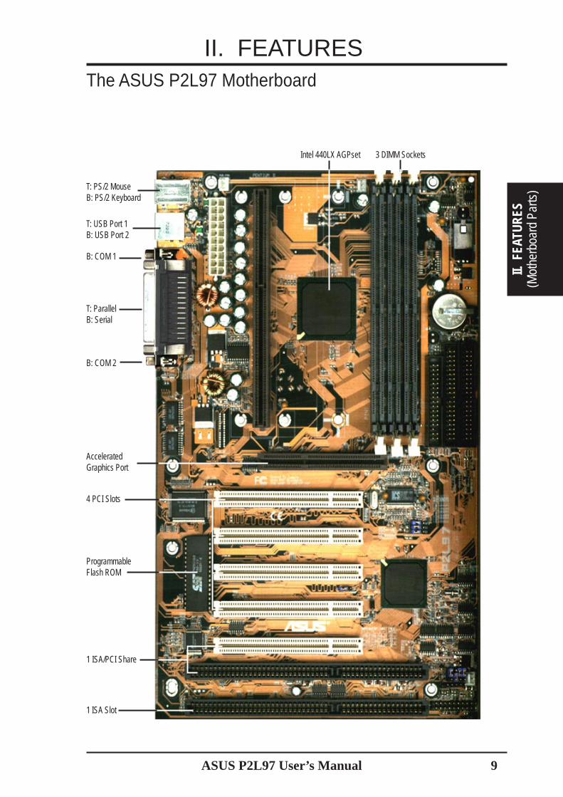
The ASUS P2L97 Motherboard
II. FEATURES
II. F
EATU
RES
(Mot
herb
oard
Par
ts)
T: USB Port 1B: USB Port 2
B: COM 1
B: COM 2
ProgrammableFlash ROM
4 PCI Slots
AcceleratedGraphics Port
1 ISA Slot
1 ISA/PCI Share
T: PS/2 MouseB: PS/2 Keyboard
T: ParallelB: Serial
3 DIMM SocketsIntel 440LX AGPset
10 ASUS P2L97 User’s Manual
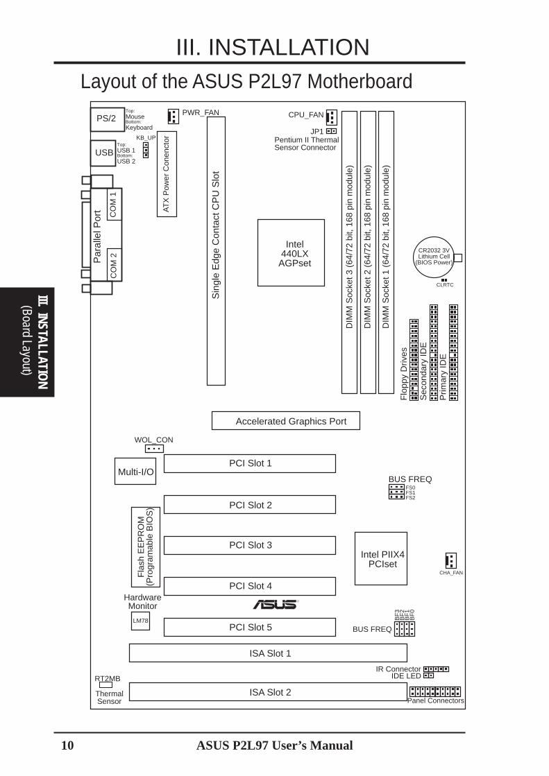
III. INSTALLATIONLayout of the ASUS P2L97 Motherboard
CR2032 3VLithium Cell
(BIOS Power)
CPU_FANPWR_FAN
CHA_FAN
LM78
Panel Connectors
IR ConnectorIDE LED
USB
PS/2
Par
alle
l Por
t
R
BUS FREQ
BF
2B
F3
BF
1B
F0
CLRTC
BUS FREQ
FS1FS0
FS2
JP1
ThermalSensor
WOL_CON
RT2MB
KB_UP
Flo
ppy
Driv
es
Sec
onda
ry ID
E
Prim
ary
IDE
Accelerated Graphics Port
PCI Slot 1
PCI Slot 2
PCI Slot 3
PCI Slot 4
PCI Slot 5
ISA Slot 1
ISA Slot 2
Intel PIIX4PCIset
Intel440LXAGPset
Fla
sh E
EP
RO
M(P
rogr
amab
le B
IOS
)
HardwareMonitor
AT
X P
ower
Con
enct
or
Sin
gle
Edg
e C
onta
ct C
PU
Slo
t
CO
M 1
CO
M 2
Top:USB 1Bottom:USB 2
Top:MouseBottom:Keyboard
Multi-I/O
DIM
M S
ocke
t 3 (
64/7
2 bi
t, 16
8 pi
n m
odul
e)
DIM
M S
ocke
t 2 (
64/7
2 bi
t, 16
8 pi
n m
odul
e)
DIM
M S
ocke
t 1 (
64/7
2 bi
t, 16
8 pi
n m
odul
e)
Pentium II ThermalSensor Connector
(Board Layout)III. INSTALLATIO
N
ASUS P2L97 User’s Manual 11
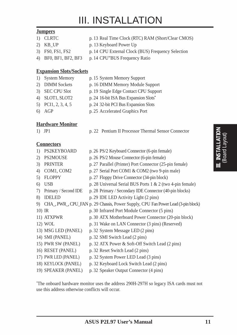
III. INSTALLATIONJumpers1) CLRTC p. 13 Real Time Clock (RTC) RAM (Short/Clear CMOS)2) KB_UP p. 13 Keyboard Power Up3) FS0, FS1, FS2 p. 14 CPU External Clock (BUS) Frequency Selection4) BF0, BF1, BF2, BF3 p. 14 CPU”BUS Frequency Ratio
Expansion Slots/Sockets1) System Memory p. 15 System Memory Support2) DIMM Sockets p. 16 DIMM Memory Module Support3) SEC CPU Slot p. 19 Single Edge Contact CPU Support4) SLOT1, SLOT2 p. 24 16-bit ISA Bus Expansion Slots*
5) PCI1, 2, 3, 4, 5 p. 2432-bit PCI Bus Expansion Slots6) AGP p. 25 Accelerated Graphics Port
Hardwar e Monitor1) JP1 p. 22 Pentium II Processor Thermal Sensor Connector
Connectors1) PS2KEYBOARD p. 26 PS/2 Keyboard Connector (6-pin female)2) PS2MOUSE p. 26PS/2 Mouse Connector (6-pin female)3) PRINTER p. 27 Parallel (Printer) Port Connector (25-pin female)4) COM1, COM2 p. 27Serial Port COM1 & COM2 (two 9-pin male)5) FLOPPY p. 27 Floppy Drive Connector (34-pin block)6) USB p. 28 Universal Serial BUS Ports 1 & 2 (two 4-pin female)7) Primary / Second IDE p. 28 Primary / Secondary IDE Connector (40-pin blocks)8) IDELED p. 29 IDE LED Activity Light (2 pins)9) CHA_, PWR_, CPU_FAN p. 29 Chassis, Power Supply, CPU Fan Power Lead (3-pin block)10) IR p. 30 Infrared Port Module Connector (5 pins)11) ATXPWR p. 30 ATX Motherboard Power Connector (20-pin block)12) WOL p. 31 Wake on LAN Connector (3 pins) (Reserved)13) MSG LED (PANEL) p. 32 System Message LED (2 pins)14) SMI (PANEL) p. 32 SMI Switch Lead (2 pins)15) PWR SW (PANEL) p. 32 ATX Power & Soft-Off Switch Lead (2 pins)16) RESET (PANEL) p. 32 Reset Switch Lead (2 pins)17) PWR LED (PANEL) p. 32 System Power LED Lead (3 pins)18) KEYLOCK (PANEL) p. 32 Keyboard Lock Switch Lead (2 pins)19) SPEAKER (PANEL) p. 32 Speaker Output Connector (4 pins)
*The onboard hardware monitor uses the address 290H-297H so legacy ISA cards must notuse this address otherwise conflicts will occur.
(Boa
rd L
ayou
t)III
. IN
STAL
LATI
ON
12 ASUS P2L97 User’s Manual
III. INSTALLATION
(Jumpers)
III. INSTALLATION
WARNING! Computer motherboards and expansion cards contain very delicateIntegrated Circuit (IC) chips. To protect them against damage from static electric-ity, you should follow some precautions whenever you work on your computer.
1. Unplug your computer when working on the inside.2. Use a grounded wrist strap before handling computer components. If you do
not have one, touch both of your hands to a safely grounded object or to ametal object, such as the power supply case.
3. Hold components by the edges and try not to touch the IC chips, leads orconnectors, or other components.
4. Place components on a grounded antistatic pad or on the bag that came withthe component whenever the components are separated from the system.
Installation StepsBefore using your computer, you must complete the following steps:
1. Set Jumpers on the Motherboard2. Install System Memory Modules3. Install the Central Processing Unit (CPU)4. Install Expansion Cards5. Connect Ribbon Cables, Cabinet Wires, and Power Supply6. Setup the BIOS Software
1. JumpersSeveral hardware settings are made through the use of jumper caps to connect jumperpins (JP) on the motherboard. See motherboard layout for locations of jumpers.The jumper settings will be described numerically, such as [----], [1-2], [2-3] for noconnection, connect pins 1&2, and connect pins 2&3, respectively. A “1” is writtenbesides pin 1 on jumpers with three pins. The jumpers will also be shown graphi-
cally such as to connect pins 1&2 and to connect pins 2&3. Jumperswith two pins will be shown as for Short (On) and for Open (Off). Formanufacturing simplicity, the jumpers may be sharing pins from other groups. Usethe diagrams in this manual instead of following the pin layout on the board. Set-tings with two jumper numbers require that both jumpers be moved together. Toconnect the pins, simply place a plastic jumper cap over the two pins as diagrammed.
ASUS P2L97 User’s Manual 13
III. INSTALLATION
III.
INST
ALLA
TIO
N(J
umpe
rs)
Jumper Settings
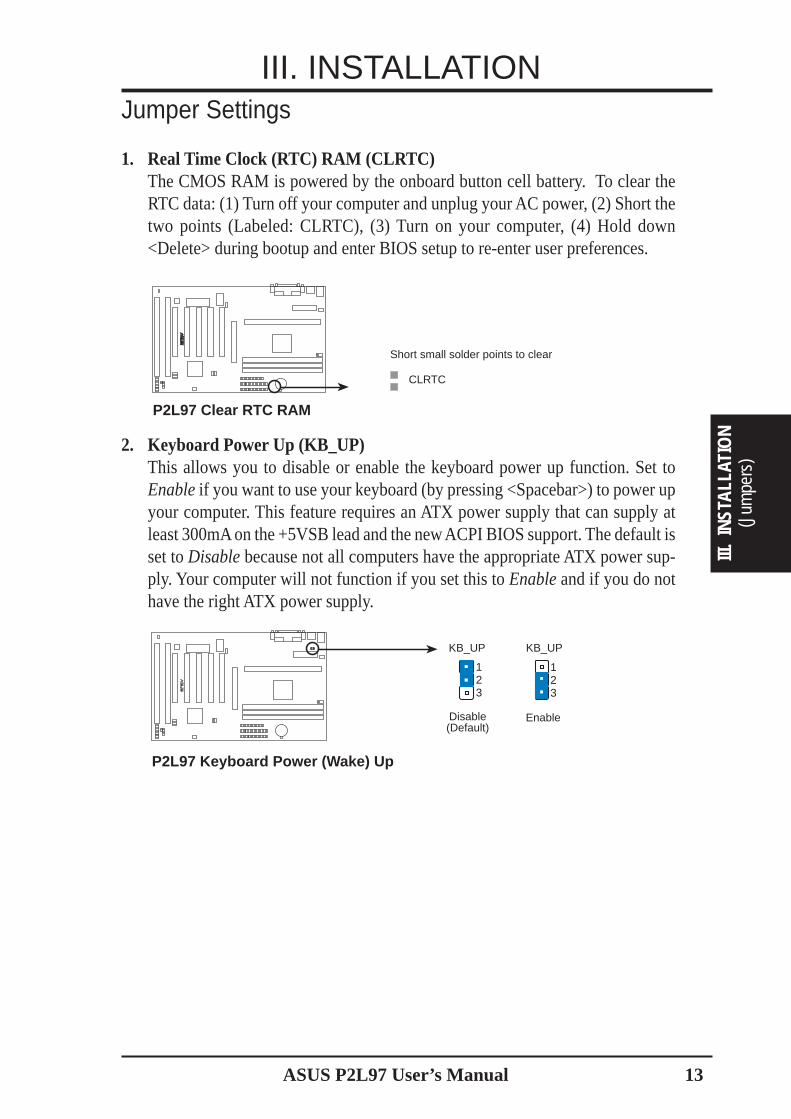
1. Real Time Clock (RTC) RAM (CLRTC)The CMOS RAM is powered by the onboard button cell battery. To clear theRTC data: (1) Turn off your computer and unplug your AC power, (2) Short thetwo points (Labeled: CLRTC), (3) Turn on your computer, (4) Hold down<Delete> during bootup and enter BIOS setup to re-enter user preferences.
Short small solder points to clear
P2L97 Clear RTC RAM
CLRTC
R
2. Keyboard Power Up (KB_UP)This allows you to disable or enable the keyboard power up function. Set toEnable if you want to use your keyboard (by pressing <Spacebar>) to power upyour computer. This feature requires an ATX power supply that can supply atleast 300mA on the +5VSB lead and the new ACPI BIOS support. The default isset to Disable because not all computers have the appropriate ATX power sup-ply. Your computer will not function if you set this to Enable and if you do nothave the right ATX power supply.
1
Disable(Default)
P2L97 Keyboard Power (Wake) Up
23
Enable
KB_UP KB_UP
123R
14 ASUS P2L97 User’s Manual
III. INSTALLATION
(Jumpers)
III. INSTALLATION
CPU Bus Frequency
CPU Core:Bus Frequency Multiple
R
4.5x(9/2)4.0x(4/1)3.5x(7/2)2.0x(2/1) 5.0x(5/1)
BF2BF1
BF3
BF0
1 2 3
BF2BF1
BF3
BF0
1 2 3
BF2BF1
BF3
BF0
1 2 3
BF2BF1
BF3
BF0
1 2 3
BF2BF1
BF3
BF0
1 2 3
60MHz 66MHz 75MHz 83MHz
FS
1F
S0
FS
2123
FS
1F
S0
FS
2
123
FS
1F
S0
FS
2
123
FS
1F
S0
FS
2
123
P2L97 CPU Jumpers
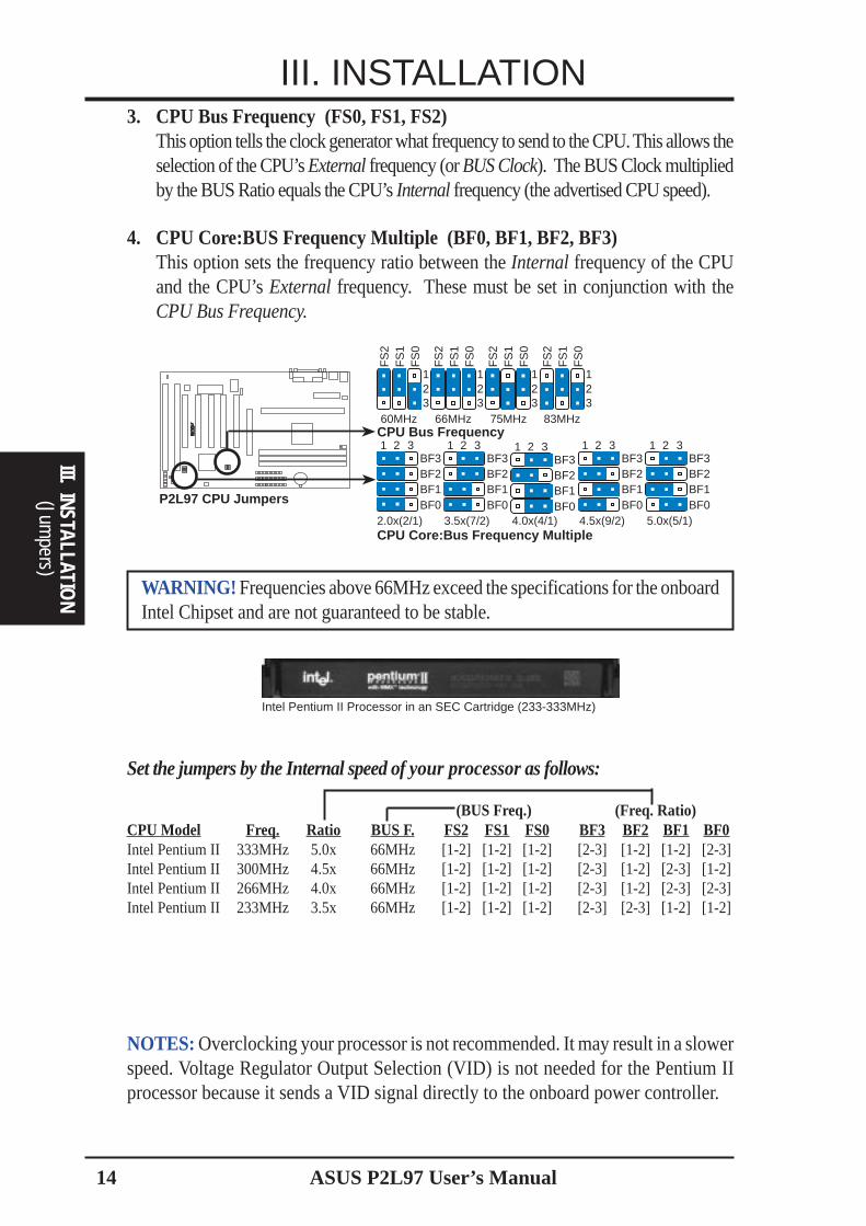
3. CPU Bus Frequency (FS0, FS1, FS2)This option tells the clock generator what frequency to send to the CPU. This allows theselection of the CPU’s External frequency (or BUS Clock). The BUS Clock multipliedby the BUS Ratio equals the CPU’s Internal frequency (the advertised CPU speed).
4. CPU Core:BUS Frequency Multiple (BF0, BF1, BF2, BF3)This option sets the frequency ratio between the Internal frequency of the CPUand the CPU’s External frequency. These must be set in conjunction with theCPU Bus Frequency.
WARNING! Frequencies above 66MHz exceed the specifications for the onboardIntel Chipset and are not guaranteed to be stable.
NOTES: Overclocking your processor is not recommended. It may result in a slowerspeed. Voltage Regulator Output Selection (VID) is not needed for the Pentium IIprocessor because it sends a VID signal directly to the onboard power controller.
Set the jumpers by the Internal speed of your processor as follows:
(BUS Freq.) (Freq. Ratio)CPU Model Freq. Ratio BUS F. FS2 FS1 FS0 BF3 BF2 BF1 BF0Intel Pentium II 333MHz 5.0x 66MHz [1-2] [1-2] [1-2] [2-3] [1-2] [1-2] [2-3]Intel Pentium II 300MHz 4.5x 66MHz [1-2] [1-2] [1-2] [2-3] [1-2] [2-3] [1-2]Intel Pentium II 266MHz 4.0x 66MHz [1-2] [1-2] [1-2] [2-3] [1-2] [2-3] [2-3]Intel Pentium II 233MHz 3.5x 66MHz [1-2] [1-2] [1-2] [2-3] [2-3] [1-2] [1-2]
Intel Pentium II Processor in an SEC Cartridge (233-333MHz)
ASUS P2L97 User’s Manual 15
(This page was intentionally left blank)
○ ○ ○ ○ ○ ○ ○ ○ ○ ○ ○ ○ ○ ○ ○ ○ ○ ○ ○ ○ ○ ○ ○ ○ ○ ○ ○ ○ ○ ○ ○ ○ ○ ○ ○ ○ ○
○ ○ ○ ○ ○ ○ ○ ○ ○ ○ ○ ○ ○ ○ ○ ○ ○ ○ ○ ○ ○ ○ ○ ○ ○ ○ ○ ○ ○ ○ ○ ○ ○ ○ ○ ○ ○
○ ○ ○ ○ ○ ○ ○ ○ ○ ○ ○ ○ ○ ○ ○ ○ ○ ○ ○ ○ ○ ○ ○ ○ ○ ○ ○ ○ ○ ○ ○ ○ ○ ○ ○ ○ ○
○ ○ ○ ○ ○ ○ ○ ○ ○ ○ ○ ○ ○ ○ ○ ○ ○ ○ ○ ○ ○ ○ ○ ○ ○ ○ ○ ○ ○ ○ ○ ○ ○ ○ ○ ○ ○
○ ○ ○ ○ ○ ○ ○ ○ ○ ○ ○ ○ ○ ○ ○ ○ ○ ○ ○ ○ ○ ○ ○ ○ ○ ○ ○ ○ ○ ○ ○ ○ ○ ○ ○ ○ ○
○ ○ ○ ○ ○ ○ ○ ○ ○ ○ ○ ○ ○ ○ ○ ○ ○ ○ ○ ○ ○ ○ ○ ○ ○ ○ ○ ○ ○ ○ ○ ○ ○ ○ ○ ○ ○
○ ○ ○ ○ ○ ○ ○ ○ ○ ○ ○ ○ ○ ○ ○ ○ ○ ○ ○ ○ ○ ○ ○ ○ ○ ○ ○ ○ ○ ○ ○ ○ ○ ○ ○ ○ ○
○ ○ ○ ○ ○ ○ ○ ○ ○ ○ ○ ○ ○ ○ ○ ○ ○ ○ ○ ○ ○ ○ ○ ○ ○ ○ ○ ○ ○ ○ ○ ○ ○ ○ ○ ○ ○
○ ○ ○ ○ ○ ○ ○ ○ ○ ○ ○ ○ ○ ○ ○ ○ ○ ○ ○ ○ ○ ○ ○ ○ ○ ○ ○ ○ ○ ○ ○ ○ ○ ○ ○ ○ ○
○ ○ ○ ○ ○ ○ ○ ○ ○ ○ ○ ○ ○ ○ ○ ○ ○ ○ ○ ○ ○ ○ ○ ○ ○ ○ ○ ○ ○ ○ ○ ○ ○ ○ ○ ○ ○
○ ○ ○ ○ ○ ○ ○ ○ ○ ○ ○ ○ ○ ○ ○ ○ ○ ○ ○ ○ ○ ○ ○ ○ ○ ○ ○ ○ ○ ○ ○ ○ ○ ○ ○ ○ ○
○ ○ ○ ○ ○ ○ ○ ○ ○ ○ ○ ○ ○ ○ ○ ○ ○ ○ ○ ○ ○ ○ ○ ○ ○ ○ ○ ○ ○ ○ ○ ○ ○ ○ ○ ○ ○
○ ○ ○ ○ ○ ○ ○ ○ ○ ○ ○ ○ ○ ○ ○ ○ ○ ○ ○ ○ ○ ○ ○ ○ ○ ○ ○ ○ ○ ○ ○ ○ ○ ○ ○ ○ ○
○ ○ ○ ○ ○ ○ ○ ○ ○ ○ ○ ○ ○ ○ ○ ○ ○ ○ ○ ○ ○ ○ ○ ○ ○ ○ ○ ○ ○ ○ ○ ○ ○ ○ ○ ○ ○
○ ○ ○ ○ ○ ○ ○ ○ ○ ○ ○ ○ ○ ○ ○ ○ ○ ○ ○ ○ ○ ○ ○ ○ ○ ○ ○ ○ ○ ○ ○ ○ ○ ○ ○ ○ ○
○ ○ ○ ○ ○ ○ ○ ○ ○ ○ ○ ○ ○ ○ ○ ○ ○ ○ ○ ○ ○ ○ ○ ○ ○ ○ ○ ○ ○ ○ ○ ○ ○ ○ ○ ○ ○
○ ○ ○ ○ ○ ○ ○ ○ ○ ○ ○ ○ ○ ○ ○ ○ ○ ○ ○ ○ ○ ○ ○ ○ ○ ○ ○ ○ ○ ○ ○ ○ ○ ○ ○ ○ ○
○ ○ ○ ○ ○ ○ ○ ○ ○ ○ ○ ○ ○ ○ ○ ○ ○ ○ ○ ○ ○ ○ ○ ○ ○ ○ ○ ○ ○ ○ ○ ○ ○ ○ ○ ○ ○
○ ○ ○ ○ ○ ○ ○ ○ ○ ○ ○ ○ ○ ○ ○ ○ ○ ○ ○ ○ ○ ○ ○ ○ ○ ○ ○ ○ ○ ○ ○ ○ ○ ○ ○ ○ ○
○ ○ ○ ○ ○ ○ ○ ○ ○ ○ ○ ○ ○ ○ ○ ○ ○ ○ ○ ○ ○ ○ ○ ○ ○ ○ ○ ○ ○ ○ ○ ○ ○ ○ ○ ○ ○
○ ○ ○ ○ ○ ○ ○ ○ ○ ○ ○ ○ ○ ○ ○ ○ ○ ○ ○ ○ ○ ○ ○ ○ ○ ○ ○ ○ ○ ○ ○ ○ ○ ○ ○ ○ ○
○ ○ ○ ○ ○ ○ ○ ○ ○ ○ ○ ○ ○ ○ ○ ○ ○ ○ ○ ○ ○ ○ ○ ○ ○ ○ ○ ○ ○ ○ ○ ○ ○ ○ ○ ○ ○
○ ○ ○ ○ ○ ○ ○ ○ ○ ○ ○ ○ ○ ○ ○ ○ ○ ○ ○ ○ ○ ○ ○ ○ ○ ○ ○ ○ ○ ○ ○ ○ ○ ○ ○ ○ ○
○ ○ ○ ○ ○ ○ ○ ○ ○ ○ ○ ○ ○ ○ ○ ○ ○ ○ ○ ○ ○ ○ ○ ○ ○ ○ ○ ○ ○ ○ ○ ○ ○ ○ ○ ○ ○
○ ○ ○ ○ ○ ○ ○ ○ ○ ○ ○ ○ ○ ○ ○ ○ ○ ○ ○ ○ ○ ○ ○ ○ ○ ○ ○ ○ ○ ○ ○ ○ ○ ○ ○ ○ ○
○ ○ ○ ○ ○ ○ ○ ○ ○ ○ ○ ○ ○ ○ ○ ○ ○ ○ ○ ○ ○ ○ ○ ○ ○ ○ ○ ○ ○ ○ ○ ○ ○ ○ ○ ○ ○
○ ○ ○ ○ ○ ○ ○ ○ ○ ○ ○ ○ ○ ○ ○ ○ ○ ○ ○ ○ ○ ○ ○ ○ ○ ○ ○ ○ ○ ○ ○ ○ ○ ○ ○ ○ ○
○ ○ ○ ○ ○ ○ ○ ○ ○ ○ ○ ○ ○ ○ ○ ○ ○ ○ ○ ○ ○ ○ ○ ○ ○ ○ ○ ○ ○ ○ ○ ○ ○ ○ ○ ○ ○
○ ○ ○ ○ ○ ○ ○ ○ ○ ○ ○ ○ ○ ○ ○ ○ ○ ○ ○ ○ ○ ○ ○ ○ ○ ○ ○ ○ ○ ○ ○ ○ ○ ○ ○ ○ ○
○ ○ ○ ○ ○ ○ ○ ○ ○ ○ ○ ○ ○ ○ ○ ○ ○ ○ ○ ○ ○ ○ ○ ○ ○ ○ ○ ○ ○ ○ ○ ○ ○ ○ ○ ○ ○
○ ○ ○ ○ ○ ○ ○ ○ ○ ○ ○ ○ ○ ○ ○ ○ ○ ○ ○ ○ ○ ○ ○ ○ ○ ○ ○ ○ ○ ○ ○ ○ ○ ○ ○ ○ ○
○ ○ ○ ○ ○ ○ ○ ○ ○ ○ ○ ○ ○ ○ ○ ○ ○ ○ ○ ○ ○ ○ ○ ○ ○ ○ ○ ○ ○ ○ ○ ○ ○ ○ ○ ○ ○
○ ○ ○ ○ ○ ○ ○ ○ ○ ○ ○ ○ ○ ○ ○ ○ ○ ○ ○ ○ ○ ○ ○ ○ ○ ○ ○ ○ ○ ○ ○ ○ ○ ○ ○ ○ ○
○ ○ ○ ○ ○ ○ ○ ○ ○ ○ ○ ○ ○ ○ ○ ○ ○ ○ ○ ○ ○ ○ ○ ○ ○ ○ ○ ○ ○ ○ ○ ○ ○ ○ ○ ○ ○
○ ○ ○ ○ ○ ○ ○ ○ ○ ○ ○ ○ ○ ○ ○ ○ ○ ○ ○ ○ ○ ○ ○ ○ ○ ○ ○ ○ ○ ○ ○ ○ ○ ○ ○ ○ ○
○ ○ ○ ○ ○ ○ ○ ○ ○ ○ ○ ○ ○ ○ ○ ○ ○ ○ ○ ○ ○ ○ ○ ○ ○ ○ ○ ○ ○ ○ ○ ○ ○ ○ ○ ○ ○
○ ○ ○ ○ ○ ○ ○ ○ ○ ○ ○ ○ ○ ○ ○ ○ ○ ○ ○ ○ ○ ○ ○ ○ ○ ○ ○ ○ ○ ○ ○ ○ ○ ○ ○ ○ ○
○ ○ ○ ○ ○ ○ ○ ○ ○ ○ ○ ○ ○ ○ ○ ○ ○ ○ ○ ○ ○ ○ ○ ○ ○ ○ ○ ○ ○ ○ ○ ○ ○ ○ ○ ○ ○
○ ○ ○ ○ ○ ○ ○ ○ ○ ○ ○ ○ ○ ○ ○ ○ ○ ○ ○ ○ ○ ○ ○ ○ ○ ○ ○ ○ ○ ○ ○ ○ ○ ○ ○ ○ ○
○ ○ ○ ○ ○ ○ ○ ○ ○ ○ ○ ○ ○ ○ ○ ○ ○ ○ ○ ○ ○ ○ ○ ○ ○ ○ ○ ○ ○ ○ ○ ○ ○ ○ ○ ○ ○
○ ○ ○ ○ ○ ○ ○ ○ ○ ○ ○ ○ ○ ○ ○ ○ ○ ○ ○ ○ ○ ○ ○ ○ ○ ○ ○ ○ ○ ○ ○ ○ ○ ○ ○ ○ ○
○ ○ ○ ○ ○ ○ ○ ○ ○ ○ ○ ○ ○ ○ ○ ○ ○ ○ ○ ○ ○ ○ ○ ○ ○ ○ ○ ○ ○ ○ ○ ○ ○ ○ ○ ○ ○
○ ○ ○ ○ ○ ○ ○ ○ ○ ○ ○ ○ ○ ○ ○ ○ ○ ○ ○ ○ ○ ○ ○ ○ ○ ○ ○ ○ ○ ○ ○ ○ ○ ○ ○ ○ ○
16 ASUS P2L97 User’s Manual
(This page was intentionally left blank)
○ ○ ○ ○ ○ ○ ○ ○ ○ ○ ○ ○ ○ ○ ○ ○ ○ ○ ○ ○ ○ ○ ○ ○ ○ ○ ○ ○ ○ ○ ○ ○ ○ ○ ○ ○ ○
○ ○ ○ ○ ○ ○ ○ ○ ○ ○ ○ ○ ○ ○ ○ ○ ○ ○ ○ ○ ○ ○ ○ ○ ○ ○ ○ ○ ○ ○ ○ ○ ○ ○ ○ ○ ○
○ ○ ○ ○ ○ ○ ○ ○ ○ ○ ○ ○ ○ ○ ○ ○ ○ ○ ○ ○ ○ ○ ○ ○ ○ ○ ○ ○ ○ ○ ○ ○ ○ ○ ○ ○ ○
○ ○ ○ ○ ○ ○ ○ ○ ○ ○ ○ ○ ○ ○ ○ ○ ○ ○ ○ ○ ○ ○ ○ ○ ○ ○ ○ ○ ○ ○ ○ ○ ○ ○ ○ ○ ○
○ ○ ○ ○ ○ ○ ○ ○ ○ ○ ○ ○ ○ ○ ○ ○ ○ ○ ○ ○ ○ ○ ○ ○ ○ ○ ○ ○ ○ ○ ○ ○ ○ ○ ○ ○ ○
○ ○ ○ ○ ○ ○ ○ ○ ○ ○ ○ ○ ○ ○ ○ ○ ○ ○ ○ ○ ○ ○ ○ ○ ○ ○ ○ ○ ○ ○ ○ ○ ○ ○ ○ ○ ○
○ ○ ○ ○ ○ ○ ○ ○ ○ ○ ○ ○ ○ ○ ○ ○ ○ ○ ○ ○ ○ ○ ○ ○ ○ ○ ○ ○ ○ ○ ○ ○ ○ ○ ○ ○ ○
○ ○ ○ ○ ○ ○ ○ ○ ○ ○ ○ ○ ○ ○ ○ ○ ○ ○ ○ ○ ○ ○ ○ ○ ○ ○ ○ ○ ○ ○ ○ ○ ○ ○ ○ ○ ○
○ ○ ○ ○ ○ ○ ○ ○ ○ ○ ○ ○ ○ ○ ○ ○ ○ ○ ○ ○ ○ ○ ○ ○ ○ ○ ○ ○ ○ ○ ○ ○ ○ ○ ○ ○ ○
○ ○ ○ ○ ○ ○ ○ ○ ○ ○ ○ ○ ○ ○ ○ ○ ○ ○ ○ ○ ○ ○ ○ ○ ○ ○ ○ ○ ○ ○ ○ ○ ○ ○ ○ ○ ○
○ ○ ○ ○ ○ ○ ○ ○ ○ ○ ○ ○ ○ ○ ○ ○ ○ ○ ○ ○ ○ ○ ○ ○ ○ ○ ○ ○ ○ ○ ○ ○ ○ ○ ○ ○ ○
○ ○ ○ ○ ○ ○ ○ ○ ○ ○ ○ ○ ○ ○ ○ ○ ○ ○ ○ ○ ○ ○ ○ ○ ○ ○ ○ ○ ○ ○ ○ ○ ○ ○ ○ ○ ○
○ ○ ○ ○ ○ ○ ○ ○ ○ ○ ○ ○ ○ ○ ○ ○ ○ ○ ○ ○ ○ ○ ○ ○ ○ ○ ○ ○ ○ ○ ○ ○ ○ ○ ○ ○ ○
○ ○ ○ ○ ○ ○ ○ ○ ○ ○ ○ ○ ○ ○ ○ ○ ○ ○ ○ ○ ○ ○ ○ ○ ○ ○ ○ ○ ○ ○ ○ ○ ○ ○ ○ ○ ○
○ ○ ○ ○ ○ ○ ○ ○ ○ ○ ○ ○ ○ ○ ○ ○ ○ ○ ○ ○ ○ ○ ○ ○ ○ ○ ○ ○ ○ ○ ○ ○ ○ ○ ○ ○ ○
○ ○ ○ ○ ○ ○ ○ ○ ○ ○ ○ ○ ○ ○ ○ ○ ○ ○ ○ ○ ○ ○ ○ ○ ○ ○ ○ ○ ○ ○ ○ ○ ○ ○ ○ ○ ○
○ ○ ○ ○ ○ ○ ○ ○ ○ ○ ○ ○ ○ ○ ○ ○ ○ ○ ○ ○ ○ ○ ○ ○ ○ ○ ○ ○ ○ ○ ○ ○ ○ ○ ○ ○ ○
○ ○ ○ ○ ○ ○ ○ ○ ○ ○ ○ ○ ○ ○ ○ ○ ○ ○ ○ ○ ○ ○ ○ ○ ○ ○ ○ ○ ○ ○ ○ ○ ○ ○ ○ ○ ○
○ ○ ○ ○ ○ ○ ○ ○ ○ ○ ○ ○ ○ ○ ○ ○ ○ ○ ○ ○ ○ ○ ○ ○ ○ ○ ○ ○ ○ ○ ○ ○ ○ ○ ○ ○ ○
○ ○ ○ ○ ○ ○ ○ ○ ○ ○ ○ ○ ○ ○ ○ ○ ○ ○ ○ ○ ○ ○ ○ ○ ○ ○ ○ ○ ○ ○ ○ ○ ○ ○ ○ ○ ○
○ ○ ○ ○ ○ ○ ○ ○ ○ ○ ○ ○ ○ ○ ○ ○ ○ ○ ○ ○ ○ ○ ○ ○ ○ ○ ○ ○ ○ ○ ○ ○ ○ ○ ○ ○ ○
○ ○ ○ ○ ○ ○ ○ ○ ○ ○ ○ ○ ○ ○ ○ ○ ○ ○ ○ ○ ○ ○ ○ ○ ○ ○ ○ ○ ○ ○ ○ ○ ○ ○ ○ ○ ○
○ ○ ○ ○ ○ ○ ○ ○ ○ ○ ○ ○ ○ ○ ○ ○ ○ ○ ○ ○ ○ ○ ○ ○ ○ ○ ○ ○ ○ ○ ○ ○ ○ ○ ○ ○ ○
○ ○ ○ ○ ○ ○ ○ ○ ○ ○ ○ ○ ○ ○ ○ ○ ○ ○ ○ ○ ○ ○ ○ ○ ○ ○ ○ ○ ○ ○ ○ ○ ○ ○ ○ ○ ○
○ ○ ○ ○ ○ ○ ○ ○ ○ ○ ○ ○ ○ ○ ○ ○ ○ ○ ○ ○ ○ ○ ○ ○ ○ ○ ○ ○ ○ ○ ○ ○ ○ ○ ○ ○ ○
○ ○ ○ ○ ○ ○ ○ ○ ○ ○ ○ ○ ○ ○ ○ ○ ○ ○ ○ ○ ○ ○ ○ ○ ○ ○ ○ ○ ○ ○ ○ ○ ○ ○ ○ ○ ○
○ ○ ○ ○ ○ ○ ○ ○ ○ ○ ○ ○ ○ ○ ○ ○ ○ ○ ○ ○ ○ ○ ○ ○ ○ ○ ○ ○ ○ ○ ○ ○ ○ ○ ○ ○ ○
○ ○ ○ ○ ○ ○ ○ ○ ○ ○ ○ ○ ○ ○ ○ ○ ○ ○ ○ ○ ○ ○ ○ ○ ○ ○ ○ ○ ○ ○ ○ ○ ○ ○ ○ ○ ○
○ ○ ○ ○ ○ ○ ○ ○ ○ ○ ○ ○ ○ ○ ○ ○ ○ ○ ○ ○ ○ ○ ○ ○ ○ ○ ○ ○ ○ ○ ○ ○ ○ ○ ○ ○ ○
○ ○ ○ ○ ○ ○ ○ ○ ○ ○ ○ ○ ○ ○ ○ ○ ○ ○ ○ ○ ○ ○ ○ ○ ○ ○ ○ ○ ○ ○ ○ ○ ○ ○ ○ ○ ○
○ ○ ○ ○ ○ ○ ○ ○ ○ ○ ○ ○ ○ ○ ○ ○ ○ ○ ○ ○ ○ ○ ○ ○ ○ ○ ○ ○ ○ ○ ○ ○ ○ ○ ○ ○ ○
○ ○ ○ ○ ○ ○ ○ ○ ○ ○ ○ ○ ○ ○ ○ ○ ○ ○ ○ ○ ○ ○ ○ ○ ○ ○ ○ ○ ○ ○ ○ ○ ○ ○ ○ ○ ○
○ ○ ○ ○ ○ ○ ○ ○ ○ ○ ○ ○ ○ ○ ○ ○ ○ ○ ○ ○ ○ ○ ○ ○ ○ ○ ○ ○ ○ ○ ○ ○ ○ ○ ○ ○ ○
○ ○ ○ ○ ○ ○ ○ ○ ○ ○ ○ ○ ○ ○ ○ ○ ○ ○ ○ ○ ○ ○ ○ ○ ○ ○ ○ ○ ○ ○ ○ ○ ○ ○ ○ ○ ○
○ ○ ○ ○ ○ ○ ○ ○ ○ ○ ○ ○ ○ ○ ○ ○ ○ ○ ○ ○ ○ ○ ○ ○ ○ ○ ○ ○ ○ ○ ○ ○ ○ ○ ○ ○ ○
○ ○ ○ ○ ○ ○ ○ ○ ○ ○ ○ ○ ○ ○ ○ ○ ○ ○ ○ ○ ○ ○ ○ ○ ○ ○ ○ ○ ○ ○ ○ ○ ○ ○ ○ ○ ○
○ ○ ○ ○ ○ ○ ○ ○ ○ ○ ○ ○ ○ ○ ○ ○ ○ ○ ○ ○ ○ ○ ○ ○ ○ ○ ○ ○ ○ ○ ○ ○ ○ ○ ○ ○ ○
○ ○ ○ ○ ○ ○ ○ ○ ○ ○ ○ ○ ○ ○ ○ ○ ○ ○ ○ ○ ○ ○ ○ ○ ○ ○ ○ ○ ○ ○ ○ ○ ○ ○ ○ ○ ○
○ ○ ○ ○ ○ ○ ○ ○ ○ ○ ○ ○ ○ ○ ○ ○ ○ ○ ○ ○ ○ ○ ○ ○ ○ ○ ○ ○ ○ ○ ○ ○ ○ ○ ○ ○ ○
○ ○ ○ ○ ○ ○ ○ ○ ○ ○ ○ ○ ○ ○ ○ ○ ○ ○ ○ ○ ○ ○ ○ ○ ○ ○ ○ ○ ○ ○ ○ ○ ○ ○ ○ ○ ○
○ ○ ○ ○ ○ ○ ○ ○ ○ ○ ○ ○ ○ ○ ○ ○ ○ ○ ○ ○ ○ ○ ○ ○ ○ ○ ○ ○ ○ ○ ○ ○ ○ ○ ○ ○ ○
○ ○ ○ ○ ○ ○ ○ ○ ○ ○ ○ ○ ○ ○ ○ ○ ○ ○ ○ ○ ○ ○ ○ ○ ○ ○ ○ ○ ○ ○ ○ ○ ○ ○ ○ ○ ○
○ ○ ○ ○ ○ ○ ○ ○ ○ ○ ○ ○ ○ ○ ○ ○ ○ ○ ○ ○ ○ ○ ○ ○ ○ ○ ○ ○ ○ ○ ○ ○ ○ ○ ○ ○ ○
ASUS P2L97 User’s Manual 17
III.
INST
ALLA
TIO
N(S
yste
m M
emor
y)
2. System Memory (DIMM)
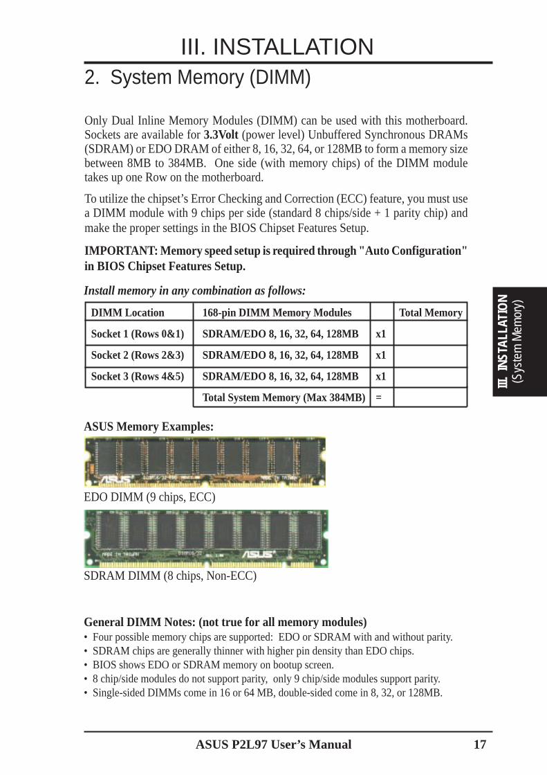
Only Dual Inline Memory Modules (DIMM) can be used with this motherboard.Sockets are available for 3.3Volt (power level) Unbuffered Synchronous DRAMs(SDRAM) or EDO DRAM of either 8, 16, 32, 64, or 128MB to form a memory sizebetween 8MB to 384MB. One side (with memory chips) of the DIMM moduletakes up one Row on the motherboard.
To utilize the chipset’s Error Checking and Correction (ECC) feature, you must usea DIMM module with 9 chips per side (standard 8 chips/side + 1 parity chip) andmake the proper settings in the BIOS Chipset Features Setup.
IMPORTANT: Memory speed setup is required through "Auto Configuration"in BIOS Chipset Features Setup.
Install memory in any combination as follows:
DIMM Location 168-pin DIMM Memory Modules Total Memory
Socket 1 (Rows 0&1) SDRAM/EDO 8, 16, 32, 64, 128MB x1
Socket 2 (Rows 2&3) SDRAM/EDO 8, 16, 32, 64, 128MB x1
Socket 3 (Rows 4&5) SDRAM/EDO 8, 16, 32, 64, 128MB x1
Total System Memory (Max 384MB) =
General DIMM Notes: (not true for all memory modules)• Four possible memory chips are supported: EDO or SDRAM with and without parity.• SDRAM chips are generally thinner with higher pin density than EDO chips.• BIOS shows EDO or SDRAM memory on bootup screen.• 8 chip/side modules do not support parity, only 9 chip/side modules support parity.• Single-sided DIMMs come in 16 or 64 MB, double-sided come in 8, 32, or 128MB.
ASUS Memory Examples:
III. INSTALLATION
EDO DIMM (9 chips, ECC)
SDRAM DIMM (8 chips, Non-ECC)
18 ASUS P2L97 User’s Manual
(System M
emory)
III. INSTALLATION
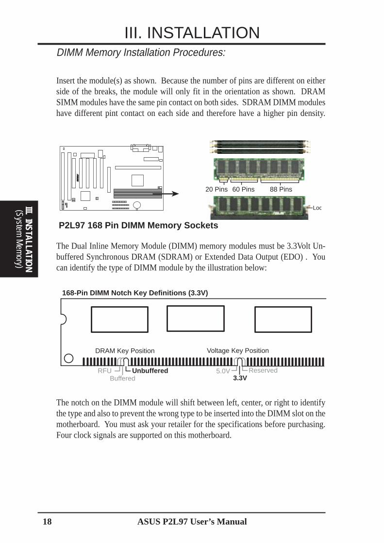
III. INSTALLATIONDIMM Memory Installation Procedures:
Insert the module(s) as shown. Because the number of pins are different on eitherside of the breaks, the module will only fit in the orientation as shown. DRAMSIMM modules have the same pin contact on both sides. SDRAM DIMM moduleshave different pint contact on each side and therefore have a higher pin density.
R
Loc
P2L97 168 Pin DIMM Memory Sockets
20 Pins 60 Pins 88 Pins
The Dual Inline Memory Module (DIMM) memory modules must be 3.3Volt Un-buffered Synchronous DRAM (SDRAM) or Extended Data Output (EDO) . Youcan identify the type of DIMM module by the illustration below:
168-Pin DIMM Notch Key Definitions (3.3V)
DRAM Key Position Voltage Key Position
UnbufferedRFUBuffered
Reserved3.3V
5.0V
The notch on the DIMM module will shift between left, center, or right to identifythe type and also to prevent the wrong type to be inserted into the DIMM slot on themotherboard. You must ask your retailer for the specifications before purchasing.Four clock signals are supported on this motherboard.
ASUS P2L97 User’s Manual 19
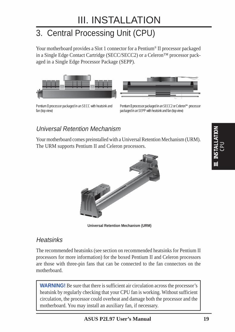
3. Central Processing Unit (CPU)
Your motherboard provides a Slot 1 connector for a Pentium® II processor packagedin a Single Edge Contact Cartridge (SECC/SECC2) or a Celeron™ processor pack-aged in a Single Edge Processor Package (SEPP).
III. INSTALLATION
CPU
III.
INST
ALLA
TIO
N
Heatsinks
The recommended heatsinks (see section on recommended heatsinks for Pentium IIprocessors for more information) for the boxed Pentium II and Celeron processorsare those with three-pin fans that can be connected to the fan connectors on themotherboard.
WARNING! Be sure that there is sufficient air circulation across the processor’sheatsink by regularly checking that your CPU fan is working. Without sufficientcirculation, the processor could overheat and damage both the processor and themotherboard. You may install an auxiliary fan, if necessary.
Universal Retention Mechanism (URM)
Universal Retention Mechanism
Your motherboard comes preinstalled with a Universal Retention Mechanism (URM).The URM supports Pentium II and Celeron processors.
Pentium II processor packaged in an SECC with heatsink andfan (top view)
Pentium II processor packaged in an SECC2 or Celeron™ processorpackaged in an SEPP with heatsink and fan (top view)
20 ASUS P2L97 User’s Manual
III. INSTALLATION
CPU
III. INSTALLATION
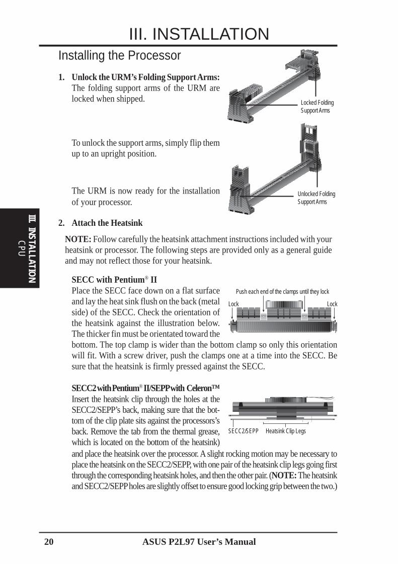
2. Attach the Heatsink
NOTE: Follow carefully the heatsink attachment instructions included with yourheatsink or processor. The following steps are provided only as a general guideand may not reflect those for your heatsink.
The URM is now ready for the installationof your processor.
Installing the Processor
1. Unlock the URM’s Folding Support Arms:The folding support arms of the URM arelocked when shipped.
SECC with Pentium® IIPlace the SECC face down on a flat surfaceand lay the heat sink flush on the back (metalside) of the SECC. Check the orientation ofthe heatsink against the illustration below.The thicker fin must be orientated toward the
SECC2 with Pentium® II/SEPP with Celeron™Insert the heatsink clip through the holes at theSECC2/SEPP’s back, making sure that the bot-tom of the clip plate sits against the processors’sback. Remove the tab from the thermal grease,which is located on the bottom of the heatsink)
Unlocked FoldingSupport Arms
Locked FoldingSupport Arms
To unlock the support arms, simply flip themup to an upright position.
Push each end of the clamps until they lock
Lock Lock
bottom. The top clamp is wider than the bottom clamp so only this orientationwill fit. With a screw driver, push the clamps one at a time into the SECC. Besure that the heatsink is firmly pressed against the SECC.
SECC2/SEPP Heatsink Clip Legs
and place the heatsink over the processor. A slight rocking motion may be necessary toplace the heatsink on the SECC2/SEPP, with one pair of the heatsink clip legs going firstthrough the corresponding heatsink holes, and then the other pair. (NOTE: The heatsinkand SECC2/SEPP holes are slightly offset to ensure good locking grip between the two.)
ASUS P2L97 User’s Manual 21
CPU
III.
INST
ALLA
TIO
N
III. INSTALLATIONWARNING! Make sure the heatsink is mounted tightly against the SECC, SECC2or SEPP; otherwise, the CPU will overheat. You may install an auxiliary fan toprovide adequate circulation across the processor’s passive heatsink.
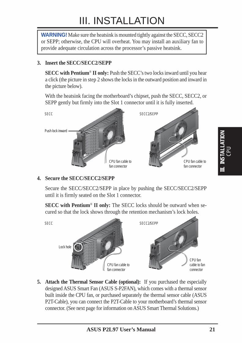
4. Secure the SECC/SECC2/SEPP
Secure the SECC/SECC2/SEPP in place by pushing the SECC/SECC2/SEPPuntil it is firmly seated on the Slot 1 connector.
SECC with Pentium® II only: The SECC locks should be outward when se-cured so that the lock shows through the retention mechanism’s lock holes.
5. Attach the Thermal Sensor Cable (optional): If you purchased the especiallydesigned ASUS Smart Fan (ASUS S-P2FAN), which comes with a thermal sensorbuilt inside the CPU fan, or purchased separately the thermal sensor cable (ASUSP2T-Cable), you can connect the P2T-Cable to your motherboard’s thermal sensorconnector. (See next page for information on ASUS Smart Thermal Solutions.)
3. Insert the SECC/SECC2/SEPP
SECC with Pentium® II only: Push the SECC’s two locks inward until you heara click (the picture in step 2 shows the locks in the outward position and inward inthe picture below).
With the heatsink facing the motherboard’s chipset, push the SECC, SECC2, orSEPP gently but firmly into the Slot 1 connector until it is fully inserted.
SECC2/SEPP
Push lock inward
SECC
SECC SECC2/SEPP
CPU fan cable tofan connector
CPU fan cable tofan connector
CPU fan cable tofan connector
CPU fancable to fanconnector
Lock hole
22 ASUS P2L97 User’s Manual
CPU
III. INSTALLATION
III. INSTALLATIONASUS Smart Thermal Solutions
ASUS provides two smart solutions to Slot 1 CPU thermal problems: the ASUSSmart Fan or ASUS S-P2FAN and the ASUS P2T-Cable.
The ASUS Smart Fan or ASUS S-P2FAN is a CPU fan for a Pentium® II processorpackaged in a Single Edge Contact Cartridge (SECC). Unlike other CPU thermalsolutions, the ASUS S-P2FAN has an integrated thermal sensor located near thecenter of the CPU heat source. The sensor is optimized by ASUS to give the mostaccurate reading of the CPU temperature, thus provides the best protection to yourcomputer system.
The ASUS P2T-Cable or thermal sensor cable can be used for a Pentium® II proces-sor packaged in a Single Edge Contact Cartridge (SECC/SECC2) or a Celeron™processor packaged in a Single Edge Processor Package (SEPP).
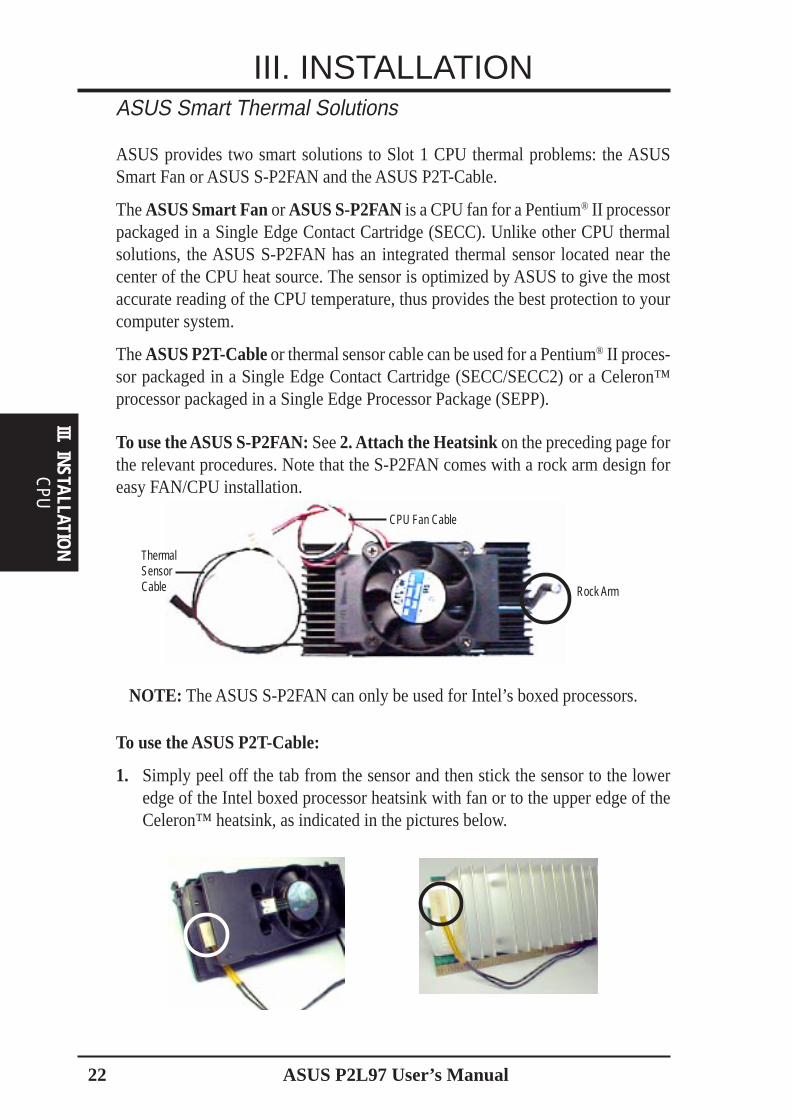
To use the ASUS S-P2FAN: See 2. Attach the Heatsink on the preceding page forthe relevant procedures. Note that the S-P2FAN comes with a rock arm design foreasy FAN/CPU installation.
To use the ASUS P2T-Cable:
1. Simply peel off the tab from the sensor and then stick the sensor to the loweredge of the Intel boxed processor heatsink with fan or to the upper edge of theCeleron™ heatsink, as indicated in the pictures below.
Rock Arm
ThermalSensorCable
NOTE: The ASUS S-P2FAN can only be used for Intel’s boxed processors.
CPU Fan Cable
ASUS P2L97 User’s Manual 23
III. INSTALLATIONRecommended Heatsinks for Pentium II Processors
The heatsinks shown in this manual are for reference purposes only. The recom-mended heatsinks for the Pentium II processor are those with three-pin fans that canbe connected to the CPU fan connector on the motherboard. These heatsinks havethe added benefits of proper heat dissipation and with the hardware monitor, theability to monitor the fan’s RPM and use the alert function through the includedLANDesk Client Manager (LDCM) software.
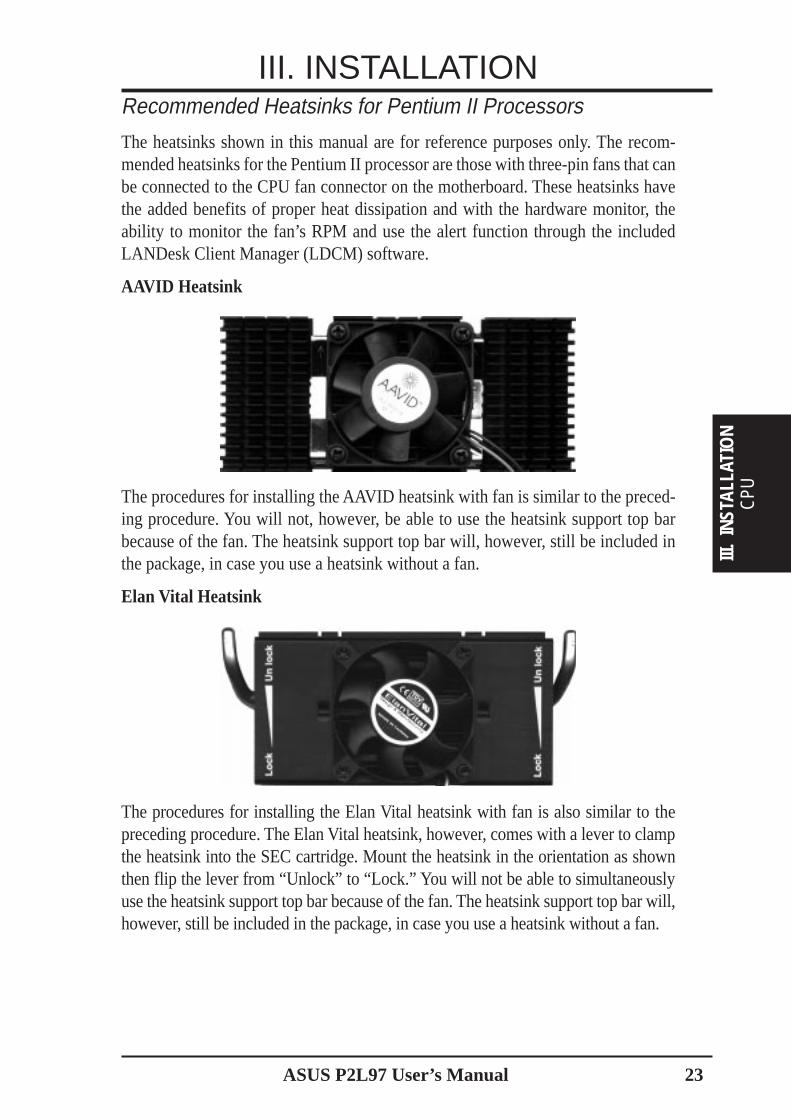
AAVID Heatsink
The procedures for installing the AAVID heatsink with fan is similar to the preced-ing procedure. You will not, however, be able to use the heatsink support top barbecause of the fan. The heatsink support top bar will, however, still be included inthe package, in case you use a heatsink without a fan.
Elan Vital Heatsink
The procedures for installing the Elan Vital heatsink with fan is also similar to thepreceding procedure. The Elan Vital heatsink, however, comes with a lever to clampthe heatsink into the SEC cartridge. Mount the heatsink in the orientation as shownthen flip the lever from “Unlock” to “Lock.” You will not be able to simultaneouslyuse the heatsink support top bar because of the fan. The heatsink support top bar will,however, still be included in the package, in case you use a heatsink without a fan.
CPU
III.
INST
ALLA
TIO
N
24 ASUS P2L97 User’s Manual
III. INSTALLATION
Expansion Cards
III. INSTALLATION
4. Expansion Cards
Expansion Card Installation Procedure1. Read the documentation for your expansion card and make any necessary hard-
ware or software settings for your expansion card, such as jumpers.
2. Remove your computer system’s cover and the bracket plate on the slot youintend to use. Keep the bracket for possible future use.
3. Carefully align the card’s connectors and press firmly.
4. Secure the card on the slot with the screw you removed above.
5. Replace the computer system’s cover.
6. Set up the BIOS if necessary(such as IRQ xx Used By ISA: Yes in PNP AND PCI SETUP)
7. Install the necessary software drivers for your expansion card.
Assigning IRQs for Expansion CardsSome expansion cards need to use an IRQ to operate. Generally, an IRQ must beexclusively assigned to one use. In a standard design, there are 16 IRQs availablebut most of them are already in use, leaving 6 IRQs free for expansion cards. If yourmotherboard has audio onboard, an extra 3 IRQs will be used, leaving 3 IRQs free.
Both ISA and PCI expansion cards may require to use IRQs. System IRQs are avail-able to cards installed in the ISA expansion bus first, then any remaining IRQs areavailable to PCI cards. Currently, there are two types of ISA cards. The original ISAexpansion card design, now referred to as legacy ISA cards, requires that you con-figure the card’s jumpers manually and then install it in any available slot on the ISAbus. You may use the Microsoft Diagnostics (MSD.EXE) utility located in the Win-dows directory to see a map of your used and free IRQs. If you use Windows 95, theResources tab under Device Manager displays the resource settings being used bya particular device (to gain access, double-click the System icon under the ControlPanel program). Ensure that no two devices share the same IRQs or your computerwill experience problems when those two devices are in use at the same time.
WARNING! Unplug your power supply when adding or removing expansioncards or other system components. Failure to do so may cause severe damage toboth your motherboard and expansion cards.
ASUS P2L97 User’s Manual 25
III. INSTALLATIONTo simplify this process, this motherboard complies with the Plug and Play (PnP)specification, which was developed to allow automatic system configuration when-ever a PnP-compliant card is added to the system. For PnP cards, IRQs are assignedautomatically from those available.
If the system has both legacy and PnP ISA cards installed, IRQs are assigned to PnPcards from those not used by legacy cards. The PCI and PNP configuration sectionof the BIOS setup utility can be used to assign which IRQs are being used by legacycards. For older legacy cards that do not work with the BIOS, you may contact yourvendor for an ISA Configuration Utility.
An IRQ number is automatically assigned to PCI expansion cards after those usedby legacy and PnP ISA cards. In the PCI bus design, the BIOS automatically assignsan IRQ to a PCI slot that contains a card requiring an IRQ. To install a PCI card, youneed to set the INT (interrupt) assignment. Since all the PCI slots on this mother-board use an INTA #, set the jumpers on your PCI cards to INT A.
Assigning DMA Channels for ISA CardsSome ISA cards, both legacy and PnP, may also need to use a DMA (Direct MemoryAccess) channel. DMA assignments for this motherboard are handled the same wayas the IRQ assignment process described earlier. You can select a DMA channel inthe PCI and PnP configuration section of the BIOS Setup utility.
IMPORTANT: To avoid conflicts, reserve the necessary IRQs and DMAs for legacyISA cards (under PNP AND PCI SETUP of the BIOS SOFTWARE, choose Yes in IRQxx Used By ISA and DMA x Used By ISA for those IRQs and DMAs you want to reserve).
ISA Cards and Hardware MonitorThe onboard hardware monitor uses the address 290H-297H so legacy ISA cardsmust not use this address or else conflicts will occur.
(DM
A C
hann
els)
III.
INST
ALLA
TIO
N
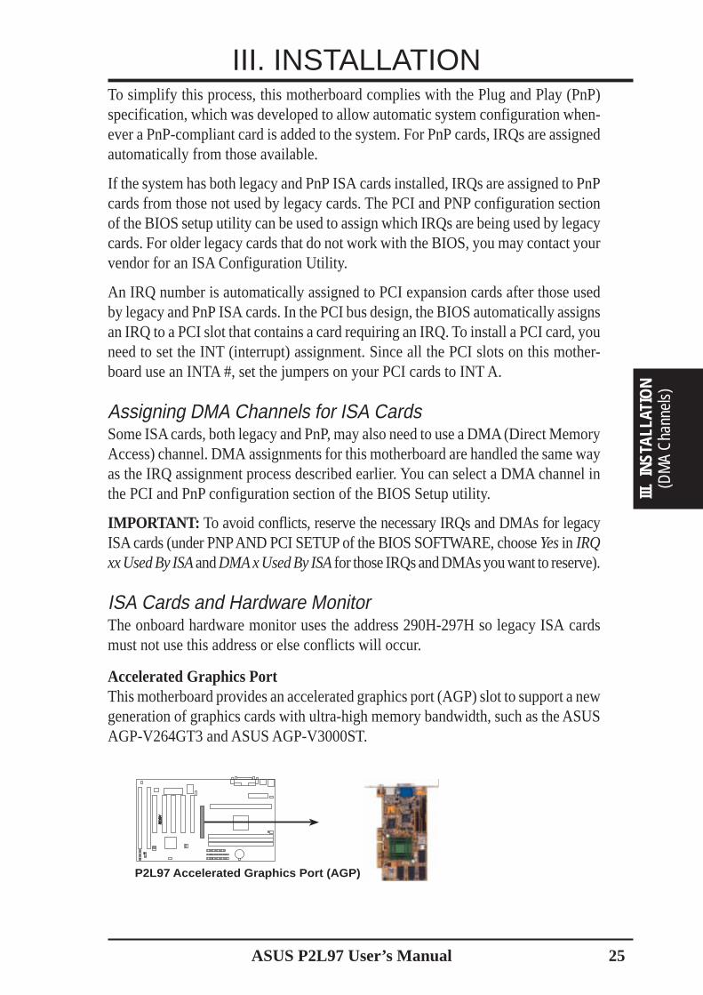
Accelerated Graphics PortThis motherboard provides an accelerated graphics port (AGP) slot to support a newgeneration of graphics cards with ultra-high memory bandwidth, such as the ASUSAGP-V264GT3 and ASUS AGP-V3000ST.
P2L97 Accelerated Graphics Port (AGP)
R
26 ASUS P2L97 User’s Manual
5. External Connectors
IMPORTANT: Ribbon cables should always be connected with the red stripe onthe Pin 1 side of the connector. The four corners of the connectors are labeled onthe motherboard. Pin 1 is the side closest to the power connector on hard drivesand floppy drives. IDE ribbon cable must be less than 18in. (46cm), with thesecond drive connector no more than 6in. (15cm) from the first connector.
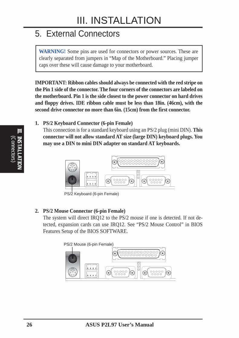
1. PS/2 Keyboard Connector (6-pin Female)This connection is for a standard keyboard using an PS/2 plug (mini DIN). Thisconnector will not allow standard AT size (large DIN) keyboard plugs. Youmay use a DIN to mini DIN adapter on standard AT keyboards.
PS/2 Keyboard (6-pin Female)
2. PS/2 Mouse Connector (6-pin Female)The system will direct IRQ12 to the PS/2 mouse if one is detected. If not de-tected, expansion cards can use IRQ12. See “PS/2 Mouse Control” in BIOSFeatures Setup of the BIOS SOFTWARE.
PS/2 Mouse (6-pin Female)
WARNING! Some pins are used for connectors or power sources. These areclearly separated from jumpers in “Map of the Motherboard.” Placing jumpercaps over these will cause damage to your motherboard.
(Connectors)
III. INSTALLATION
III. INSTALLATION
ASUS P2L97 User’s Manual 27
III. INSTALLATION
(DM
A C
hann
els)
III.
INST
ALLA
TIO
N(C
onne
ctor
s)III
. IN
STAL
LATI
ON
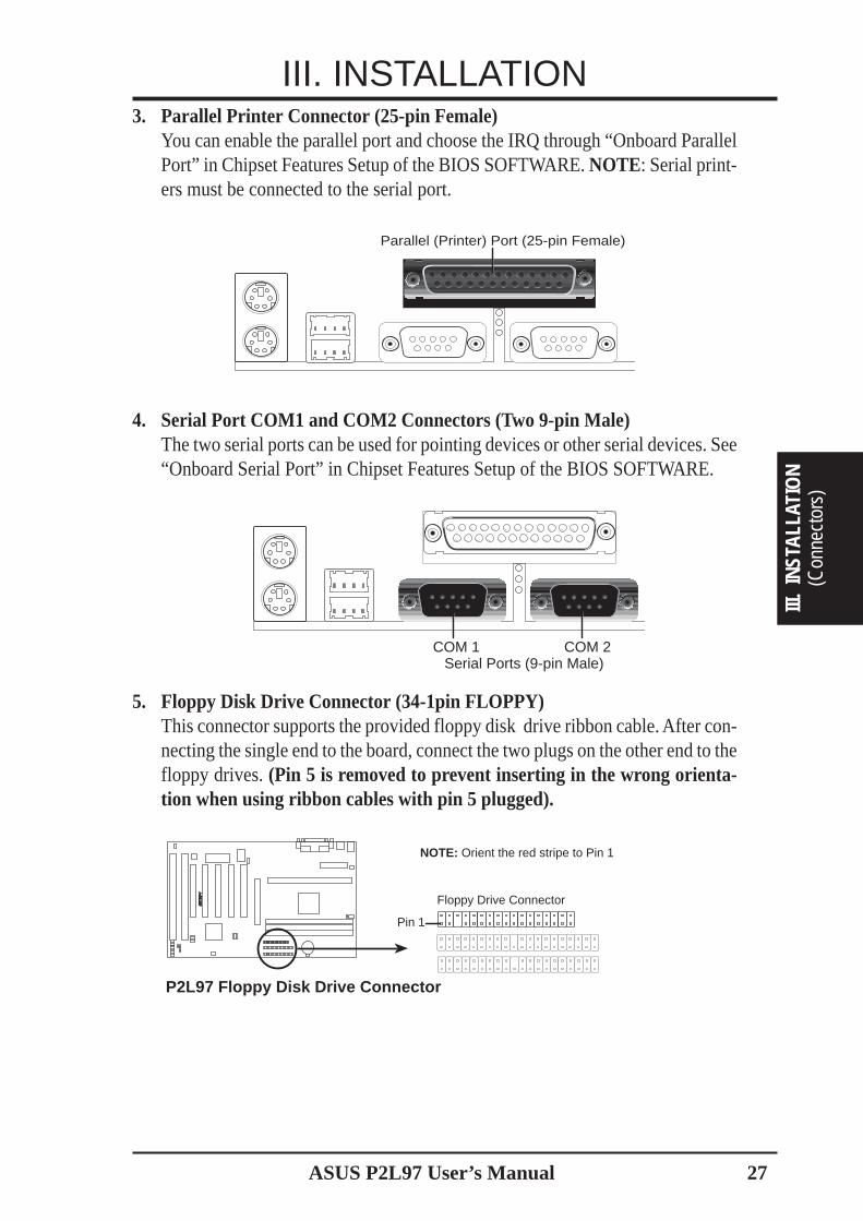
3. Parallel Printer Connector (25-pin Female)You can enable the parallel port and choose the IRQ through “Onboard ParallelPort” in Chipset Features Setup of the BIOS SOFTWARE. NOTE: Serial print-ers must be connected to the serial port.
Parallel (Printer) Port (25-pin Female)
4. Serial Port COM1 and COM2 Connectors (Two 9-pin Male)The two serial ports can be used for pointing devices or other serial devices. See“Onboard Serial Port” in Chipset Features Setup of the BIOS SOFTWARE.
COM 1 COM 2Serial Ports (9-pin Male)
5. Floppy Disk Drive Connector (34-1pin FLOPPY)This connector supports the provided floppy disk drive ribbon cable. After con-necting the single end to the board, connect the two plugs on the other end to thefloppy drives. (Pin 5 is removed to prevent inserting in the wrong orienta-tion when using ribbon cables with pin 5 plugged).
Floppy Drive Connector
Pin 1
P2L97 Floppy Disk Drive Connector
NOTE: Orient the red stripe to Pin 1
R
28 ASUS P2L97 User’s Manual
(Connectors)
III. INSTALLATION
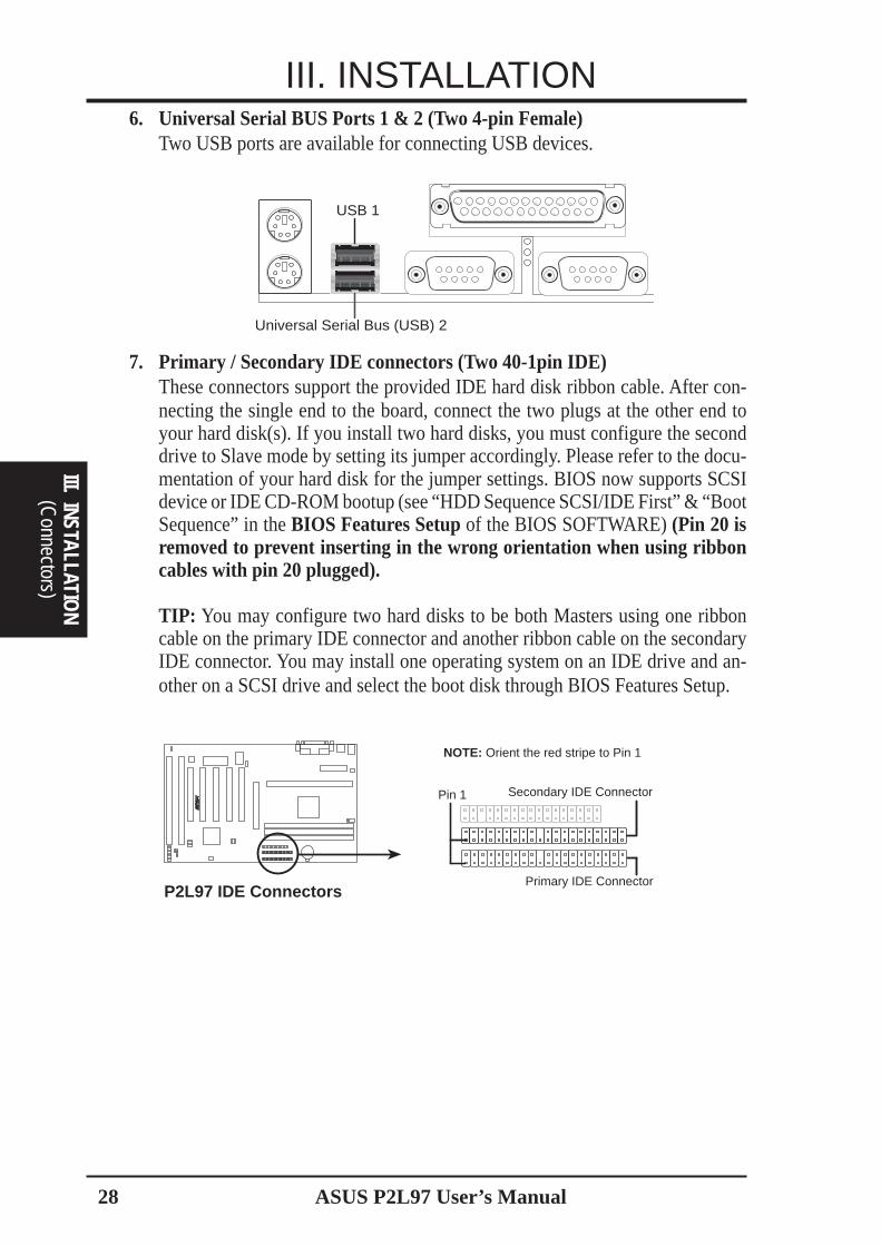
III. INSTALLATION6. Universal Serial BUS Ports 1 & 2 (Two 4-pin Female)
Two USB ports are available for connecting USB devices.
Universal Serial Bus (USB) 2
USB 1
7. Primary / Secondary IDE connectors (Two 40-1pin IDE)These connectors support the provided IDE hard disk ribbon cable. After con-necting the single end to the board, connect the two plugs at the other end toyour hard disk(s). If you install two hard disks, you must configure the seconddrive to Slave mode by setting its jumper accordingly. Please refer to the docu-mentation of your hard disk for the jumper settings. BIOS now supports SCSIdevice or IDE CD-ROM bootup (see “HDD Sequence SCSI/IDE First” & “BootSequence” in the BIOS Features Setup of the BIOS SOFTWARE) (Pin 20 isremoved to prevent inserting in the wrong orientation when using ribboncables with pin 20 plugged).
TIP: You may configure two hard disks to be both Masters using one ribboncable on the primary IDE connector and another ribbon cable on the secondaryIDE connector. You may install one operating system on an IDE drive and an-other on a SCSI drive and select the boot disk through BIOS Features Setup.
Primary IDE Connector
Pin 1 Secondary IDE Connector
P2L97 IDE Connectors
NOTE: Orient the red stripe to Pin 1
R
ASUS P2L97 User’s Manual 29
III. INSTALLATION
(Con
nect
ors)
III.
INST
ALLA
TIO
N
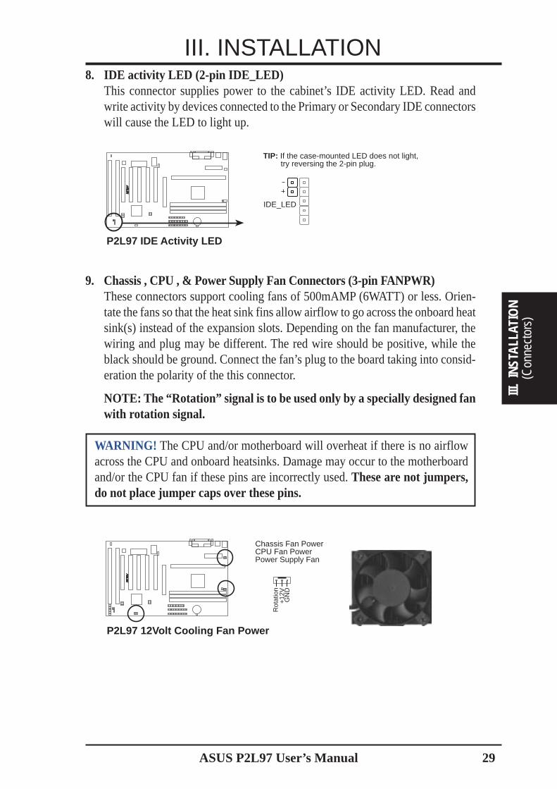
8. IDE activity LED (2-pin IDE_LED)This connector supplies power to the cabinet’s IDE activity LED. Read andwrite activity by devices connected to the Primary or Secondary IDE connectorswill cause the LED to light up.
P2L97 IDE Activity LED
TIP: If the case-mounted LED does not light, try reversing the 2-pin plug.
IDE_LED
R
9. Chassis , CPU , & Power Supply Fan Connectors (3-pin FANPWR)These connectors support cooling fans of 500mAMP (6WATT) or less. Orien-tate the fans so that the heat sink fins allow airflow to go across the onboard heatsink(s) instead of the expansion slots. Depending on the fan manufacturer, thewiring and plug may be different. The red wire should be positive, while theblack should be ground. Connect the fan’s plug to the board taking into consid-eration the polarity of the this connector.
NOTE: The “Rotation” signal is to be used only by a specially designed fanwith rotation signal.
WARNING! The CPU and/or motherboard will overheat if there is no airflowacross the CPU and onboard heatsinks. Damage may occur to the motherboardand/or the CPU fan if these pins are incorrectly used. These are not jumpers,do not place jumper caps over these pins.
P2L97 12Volt Cooling Fan Power
Chassis Fan PowerCPU Fan PowerPower Supply Fan
GN
D
Rot
atio
n+
12V
R
30 ASUS P2L97 User’s Manual
III. INSTALLATION
(Connectors)
III. INSTALLATION
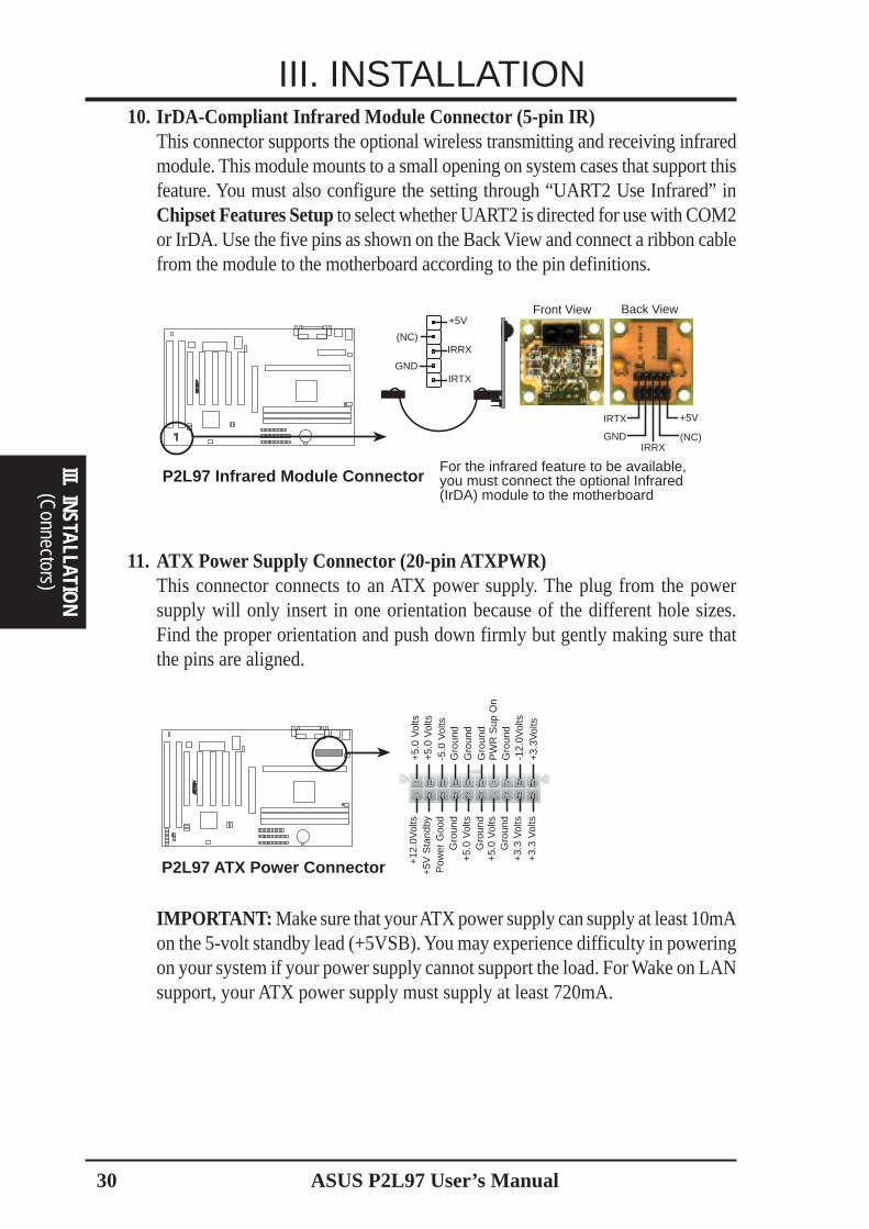
10. IrDA-Compliant Infrared Module Connector (5-pin IR)This connector supports the optional wireless transmitting and receiving infraredmodule. This module mounts to a small opening on system cases that support thisfeature. You must also configure the setting through “UART2 Use Infrared” inChipset Features Setup to select whether UART2 is directed for use with COM2or IrDA. Use the five pins as shown on the Back View and connect a ribbon cablefrom the module to the motherboard according to the pin definitions.
Front View
+5VIRTX
IRRX(NC)GND
Back View
P2L97 Infrared Module ConnectorFor the infrared feature to be available,you must connect the optional Infrared(IrDA) module to the motherboard
+5V
IRRX
IRTX
(NC)
GND
R
11. ATX Power Supply Connector (20-pin ATXPWR)This connector connects to an ATX power supply. The plug from the powersupply will only insert in one orientation because of the different hole sizes.Find the proper orientation and push down firmly but gently making sure thatthe pins are aligned.
P2L97 ATX Power Connector
+3.
3Vol
ts-1
2.0V
olts
Gro
und
PW
R S
up O
nG
roun
dG
roun
dG
roun
d-5
.0 V
olts
+5.
0 V
olts
+5.
0 V
olts
Pow
er G
ood
+12
.0V
olts
+3.
3 V
olts
+3.
3 V
olts
Gro
und
+5.
0 V
olts
Gro
und
+5.
0 V
olts
Gro
und
+5V
Sta
ndby
R
IMPORTANT: Make sure that your ATX power supply can supply at least 10mAon the 5-volt standby lead (+5VSB). You may experience difficulty in poweringon your system if your power supply cannot support the load. For Wake on LANsupport, your ATX power supply must supply at least 720mA.
ASUS P2L97 User’s Manual 31
III. INSTALLATION
(Con
nect
ors)
III.
INST
ALLA
TIO
N
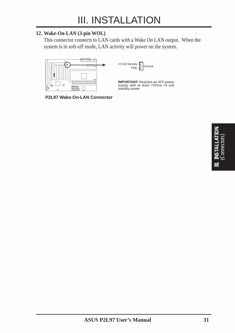
12. Wake-On-LAN (3-pin WOL)This connector connects to LAN cards with a Wake On LAN output. When thesystem is in soft-off mode, LAN activity will power on the system.
R
IMPORTANT: Requires an ATX powersupply with at least 720ma +5 voltstandby power
P2L97 Wake-On-LAN Connector
+5 Volt StandbyPME
Ground

32 ASUS P2L97 User’s Manual
III. INSTALLATION
(Connectors)
III. INSTALLATION
13. Message LED Lead (MSG LED)This indicates whether a message has been received from a fax/modem. TheLED will remain lit when there is no signal and blink when there is data transferor mail waiting in the inbox. This function requires ACPI OS and driver support.
14. System Management Interrupt Lead (SMI)This allows the user to manually place the system into a suspend mode or “Green”mode where system activity will be instantly decreased to save electricity andexpand the life of certain components when the system is not in use. This 2-pinconnector (see the figure below) connects to the case-mounted suspend switch.If you do not have a switch for the connector, you may use the “Turbo Switch”since it does not have a function. SMI is activated when it detects a short to openmoment and therefore leaving it shorted will not cause any problems. May re-quire one or two pushes depending on the position of the switch. Wake-up canbe controlled by settings in the BIOS but the keyboard will always allow wake-up (the SMI lead cannot wake-up the system). If you want to use this connector,“Suspend Switch” in the Power Management Setup of the BIOS SOFTWAREsection should be on the default setting of Enable.
15. ATX Power Switch / Soft Power Switch (PWR SW)The system power is controlled by a momentary switch connected to this lead.Pushing the button once will switch the system between ON and SLEEP. Push-ing the switch while in the ON mode for more than 4 seconds will turn thesystem off. The system power LED shows the status of the system’s power.
16. Reset Switch Lead (RESET)This 2-pin connector connects to the case-mounted reset switch for rebootingyour computer without having to turn off your power switch. This is a preferredmethod of rebooting in order to prolong the life of the system’s power supply.
17. System Power LED (PWR LED)This 3-pin connector connects the system power LED, which lights when thesystem is powered on and blinks when it is in sleep mode.
18. Keyboard Lock Switch Lead (KEYLOCK)This 2-pin connector connects to the case-mounted key switch to allow key-board locking.
19. Speaker Connector (SPEAKER)This 4-pin connector connects to the case-mounted speaker.
P2L97 System Panel Connections
PLED
Ground
MLED
PWR_SW#
* Requires an ATX power supply.
+5 V
KEYLOCK
+5V
SPKR
Keyboard Lock
SpeakerConnector
Power LED
Ground
+5 V
Reset SW
SMI Lead
MessageLED
ATX PowerSwitch*
ExtSMI#
Ground
ResetConGroundGround
Ground
R

ASUS P2L97 User’s Manual 33
III. INSTALLATION
(Pow
er C
onne
ctio
ns)
III.
INST
ALLA
TIO
N
Power Connection Procedures1. After all connections are made, close the system case cover.
2. Be sure that all switches are off (in some systems, marked with ).
3. Connect the power supply cord into the power supply located on the back ofyour system case according to your system user’s manual.
4. Connect the power cord into a power outlet that is equipped with a surge protector.
5. You may then turn on your devices in the following order:a. Your monitorb. External SCSI devices (starting with the last device on the chain)c. Your system power. For ATX power supplies, you need to switch
on the power supply as well as press the ATX power switch on thefront of the case.
6. The power LED on the front panel of the system case will light. For ATX powersupplies, the system LED will light when the ATX power switch is pressed. Themonitor LED may light up after the system’s if it complies with “green” stan-dards or if it has a power standby feature. The system will then run power-ontests. While the tests are running, additional messages will appear on the screen.If you do not see anything within 30 seconds from the time you turn on thepower, the system may have failed a power-on test. Recheck your jumper set-tings and connections or call your retailer for assistance.
7. During power-on, hold down <Delete> to enter BIOS setup. Follow the instruc-tions in the next section, BIOS SOFTWARE.
* Powering Off your computer: You must first exit or shut down your operatingsystem before switching off the power switch. For ATX power supplies, youcan press the ATX power switch after exiting or shutting down your operatingsystem. If you use Windows 95, click the Start button, click Shut Down, andthen click Shut down the computer?. The system will give three quick beepsafter about 30 seconds and then power off after Windows shuts down.
NOTE: The message “You can now safely turn off your computer” will notappear when shutting down with ATX power supplies.
ASUS P2L97 User’s Manual34
IV. BIOS
(Flash Mem
ory Writer)
IV. BIOS SOFTWAREFlash Memory Writer Utility
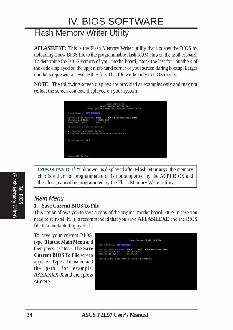
AFLASH.EXE: This is the Flash Memory Writer utility that updates the BIOS byuploading a new BIOS file to the programmable flash ROM chip on the motherboard.To determine the BIOS version of your motherboard, check the last four numbers ofthe code displayed on the upper left-hand corner of your screen during bootup. Largernumbers represent a newer BIOS file. This file works only in DOS mode.
NOTE: The following screen displays are provided as examples only and may notreflect the screen contents displayed on your system.
Main Menu1. Save Current BIOS To FileThis option allows you to save a copy of the original motherboard BIOS in case youneed to reinstall it. It is recommended that you save AFLASH.EXE and the BIOSfile to a bootable floppy disk.
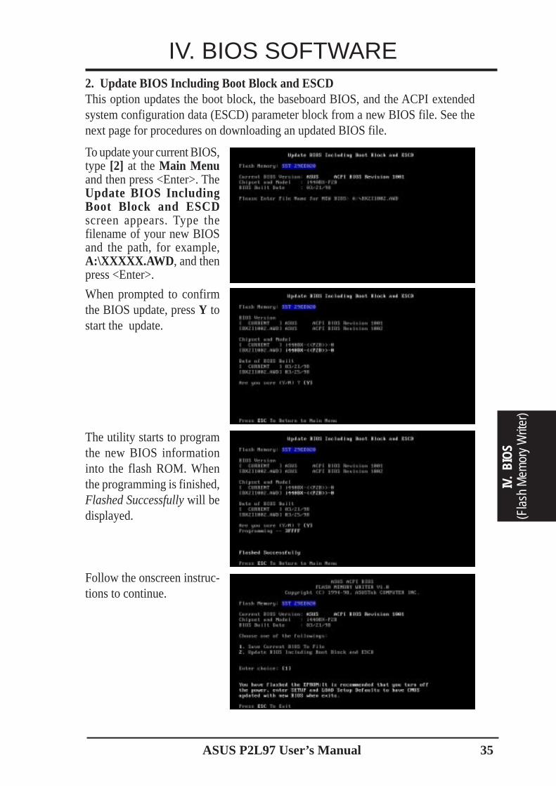
To save your current BIOS,type [1] at the Main Menu andthen press <Enter>. The SaveCurrent BIOS To File screenappears. Type a filename andthe path, for example,A:\XXXXX-X and then press<Enter>.
IMPORTANT! If “unknown” is displayed after Flash Memory:, the memorychip is either not programmable or is not supported by the ACPI BIOS andtherefore, cannot be programmed by the Flash Memory Writer utility.
ASUS P2L97 User’s Manual 35
IV.
BIO
S(F
lash
Mem
ory
Writ
er)
IV. BIOS SOFTWARE
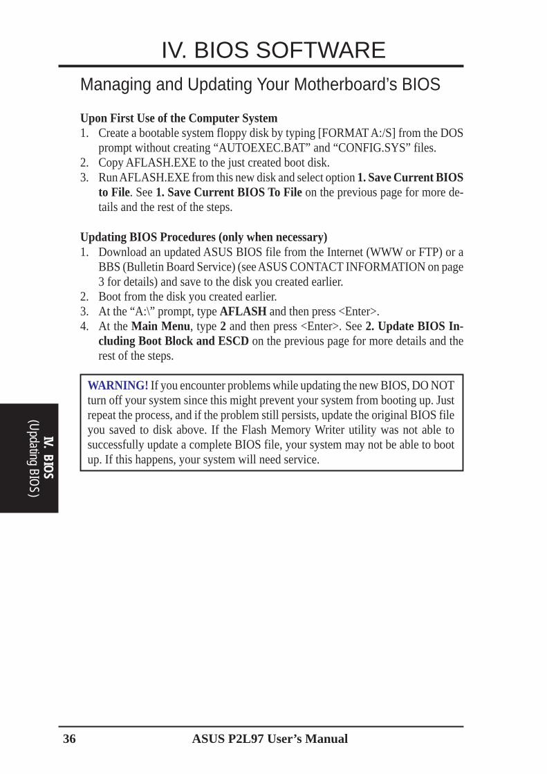
When prompted to confirmthe BIOS update, press Y tostart the update.
2. Update BIOS Including Boot Block and ESCDThis option updates the boot block, the baseboard BIOS, and the ACPI extendedsystem configuration data (ESCD) parameter block from a new BIOS file. See thenext page for procedures on downloading an updated BIOS file.
The utility starts to programthe new BIOS informationinto the flash ROM. Whenthe programming is finished,Flashed Successfully will bedisplayed.
To update your current BIOS,type [2] at the Main Menuand then press <Enter>. TheUpdate BIOS IncludingBoot Block and ESCDscreen appears. Type thefilename of your new BIOSand the path, for example,A:\XXXXX.AWD , and thenpress <Enter>.
Follow the onscreen instruc-tions to continue.
ASUS P2L97 User’s Manual36
IV. BIOS
(Updating BIO
S)
IV. BIOS SOFTWAREManaging and Updating Your Motherboard’s BIOS
Upon First Use of the Computer System1. Create a bootable system floppy disk by typing [FORMAT A:/S] from the DOS
prompt without creating “AUTOEXEC.BAT” and “CONFIG.SYS” files.2. Copy AFLASH.EXE to the just created boot disk.3. Run AFLASH.EXE from this new disk and select option 1. Save Current BIOS
to File. See 1. Save Current BIOS To File on the previous page for more de-tails and the rest of the steps.
Updating BIOS Procedures (only when necessary)1. Download an updated ASUS BIOS file from the Internet (WWW or FTP) or a
BBS (Bulletin Board Service) (see ASUS CONTACT INFORMATION on page3 for details) and save to the disk you created earlier.
2. Boot from the disk you created earlier.3. At the “A:\” prompt, type AFLASH and then press <Enter>.4. At the Main Menu, type 2 and then press <Enter>. See 2. Update BIOS In-
cluding Boot Block and ESCD on the previous page for more details and therest of the steps.
WARNING! If you encounter problems while updating the new BIOS, DO NOTturn off your system since this might prevent your system from booting up. Justrepeat the process, and if the problem still persists, update the original BIOS fileyou saved to disk above. If the Flash Memory Writer utility was not able tosuccessfully update a complete BIOS file, your system may not be able to bootup. If this happens, your system will need service.
ASUS P2L97 User’s Manual 37
IV. BIOS SOFTWARE6. BIOS Setup
IV.
BIO
S(B
IOS
Setu
p)
The motherboard supports two programmable Flash ROM chips: 5 Volt and 12 Volt.Either of these memory chips can be updated when BIOS upgrades are released.Use the Flash Memory Writer utility to download the new BIOS file into the ROMchip as described in detail in this section.
All computer motherboards provide a Setup utility program for specifying the sys-tem configuration and settings. If your motherboard came in a computer system, theproper configuration entries may have already been made. If so, invoke the Setuputility, as described later, and take note of the configuration settings for future refer-ence; in particular, the hard disk specifications.
If you are installing the motherboard, reconfiguring your system or you receive aRun Setup message, you will need to enter new setup information. This sectiondescribes how to configure your system using this utility.
The BIOS ROM of the system stores the Setup utility. When you turn on the com-puter, the system provides you with the opportunity to run this program. This ap-pears during the Power-On Self Test (POST). Press <Delete> to call up the Setuputility. If you are a little bit late pressing the mentioned key(s), POST will continuewith its test routines, thus preventing you from calling up Setup. If you still need tocall Setup, reset the system by pressing <Ctrl> + <Alt> + <Delete>, or by pressingthe Reset button on the system case. You can also restart by turning the system offand then back on again. But do so only if the first two methods fail.
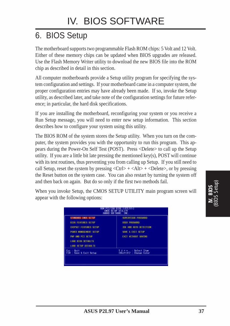
When you invoke Setup, the CMOS SETUP UTILITY main program screen willappear with the following options:
ASUS P2L97 User’s Manual38
IV. BIOS SOFTWARE
IV. BIOS
(Standard CM
OS)
Load DefaultsThe “Load BIOS Defaults” option loads the minimum settings for troubleshooting.“Load Setup Defaults”, on the other hand, is for loading optimized defaults forregular use. Choosing defaults at this level, will modify all applicable settings.
A section at the bottom of the above screen displays the control keys for this screen.Take note of these keys and their respective uses. Another section just below thecontrol keys section displays information on the currently highlighted item in the list.
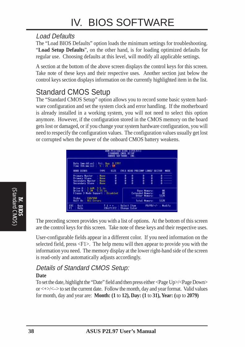
Standard CMOS SetupThe “Standard CMOS Setup” option allows you to record some basic system hard-ware configuration and set the system clock and error handling. If the motherboardis already installed in a working system, you will not need to select this optionanymore. However, if the configuration stored in the CMOS memory on the boardgets lost or damaged, or if you change your system hardware configuration, you willneed to respecify the configuration values. The configuration values usually get lostor corrupted when the power of the onboard CMOS battery weakens.
The preceding screen provides you with a list of options. At the bottom of this screenare the control keys for this screen. Take note of these keys and their respective uses.
User-configurable fields appear in a different color. If you need information on theselected field, press <F1>. The help menu will then appear to provide you with theinformation you need. The memory display at the lower right-hand side of the screenis read-only and automatically adjusts accordingly.
Details of Standard CMOS Setup:DateTo set the date, highlight the “Date” field and then press either <Page Up>/<Page Down>or <+>/<–> to set the current date. Follow the month, day and year format. Valid valuesfor month, day and year are: Month: (1 to 12), Day: (1 to 31), Year: (up to 2079)
ASUS P2L97 User’s Manual 39
IV. BIOS SOFTWARE
IV.
BIO
S(S
tand
ard
CM
OS)
TimeTo set the time, highlight the “Time” field and then press either <Page Up>/<Page Down>or <+>/<–> to set the current time. Follow the hour, minute and second format. Validvalues for hour, minute and second are: (Hour: (00 to 23), Minute: (00 to 59), Second:(00 to 59).
NOTE: You can bypass the date and time prompts by creating an AUTOEXEC.BATfile. For information on how to create this file, please refer to the MS-DOS manual.
Hard DisksThis field records the specifications for all non-SCSI hard disk drives installed inyour system. The onboard PCI IDE connectors provide Primary and Secondarychannels for connecting up to four IDE hard disks or other IDE devices. Each chan-nel can support up to two hard disks; the first of which is the “master” and thesecond is the “slave”.
Specifications for SCSI hard disks need not to be entered here since they operateusing device drivers and are not supported by any the BIOS. If you install either theoptional PCI-SC200 or PCI-SC860 SCSI controller card into the motherboard, seesection VI for instructions. If you install other vendor’s SCSI controller card, referto their respective documentations on how to install the required SCSI drivers.
For IDE hard disk drive setup, you can:• Use the Auto setting for detection during bootup.• Use the IDE HDD AUTO DETECTION in the main menu to automatically
enter the drive specifications.• Enter the specifications yourself manually by using the “User” option.
The entries for specifying the hard disk type include CYLS (number of cylinders),HEAD (number of read/write heads), PRECOMP (write precompensation), LANDZ(landing zone), SECTOR (number of sectors) and MODE . The SIZE field auto-matically adjusts according to the configuration you specify. The documentationthat comes with your hard disk should provide you with the information regardingthe drive specifications.
The MODE entry is for IDE hard disks only, and can be ignored for MFM and ESDIdrives. This entry provides three options: Normal, Large, LBA, or Auto (see below).Set MODE to the Normal for IDE hard disk drives smaller than 528MB; set it toLBA for drives over 528MB that support Logical Block Addressing (LBA) to allowlarger IDE hard disks; set it to Large for drives over 528MB that do not supportLBA. Large type of drive can only be used with MS-DOS and is very uncommon.Most IDE drives over 528MB support the LBA mode.
ASUS P2L97 User’s Manual40
IV. BIOS SOFTWARE
IV. BIOS
(Standard CM
OS)
Auto detection of hard disks on bootupFor each field: Primary Master, Primary Slave, Secondary Master, and SecondarySlave, you can select Auto under the TYPE and MODE fields. This will enable autodetection of your IDE hard disk during bootup. This will allow you to change yourhard disks (with the power off) and then power on without having to reconfigureyour hard disk type. If you use older hard disks that do not support this feature, thenyou must configure the hard disk in the standard method as described earlier by the“User” option.
NOTE: After the IDE hard disk drive information has been entered into BIOS, newIDE hard disk drives must be partitioned (such as with FDISK) and then formattedbefore data can be read from and write on. Primary IDE hard disk drives must haveits partition set to active (also possible with FDISK).
NOTE: SETUP Defaults are noted in parenthesis next to each function heading.
Drive A / Drive B (None)These fields record the types of floppy disk drives installed in your system. Theavailable options for drives A and B are: 360K, 5.25 in.; 1.2M, 5.25 in.; 720K, 3.5in.; 1.44M, 3.5 in.; 2.88M, 3.5 in.; None
To enter the configuration value for a particular drive, highlight its correspondingfield and then select the drive type using the left- or right-arrow keys.
Floppy 3 Mode Support (Disabled)This is the Japanese standard floppy drive. The standard stores 1.2MB in a 3.5inchdiskette. This is normally disabled but you may choose from either: Drive A, DriveB, Both, and Disabled
Video (EGA/VGA)Set this field to the type of video display card installed in your system. The optionsare EGA/VGA, CGA 40, CGA 80, and MONO (for Hercules or MDA).
If you are using a VGA or any higher resolution card, choose EGA/VGA.
Halt On (All Errors)This field determines which types of errors will cause the system to halt. Choose fromAll Errors; No Errors; All,But Keyboard; All,But Diskette; and All,But Disk/Key.
ASUS P2L97 User’s Manual 41
IV. BIOS SOFTWARE
IV.
BIO
S(B
IOS
Feat
ures
)
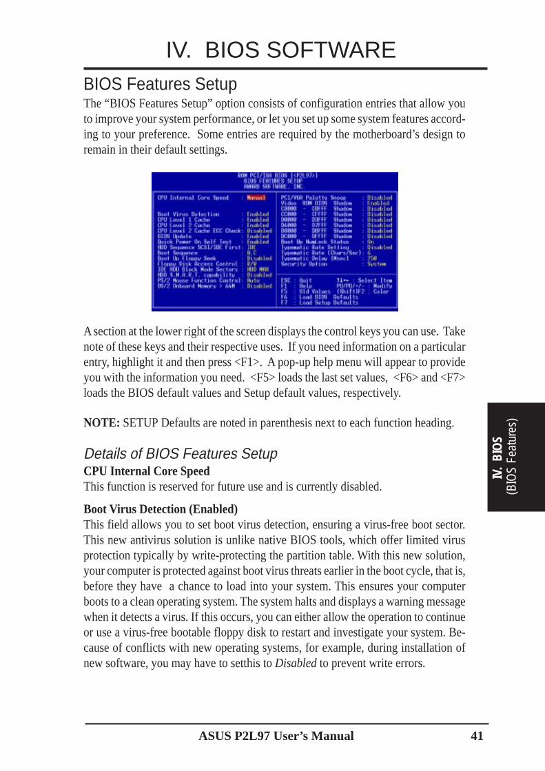
BIOS Features SetupThe “BIOS Features Setup” option consists of configuration entries that allow youto improve your system performance, or let you set up some system features accord-ing to your preference. Some entries are required by the motherboard’s design toremain in their default settings.
A section at the lower right of the screen displays the control keys you can use. Takenote of these keys and their respective uses. If you need information on a particularentry, highlight it and then press <F1>. A pop-up help menu will appear to provideyou with the information you need. <F5> loads the last set values, <F6> and <F7>loads the BIOS default values and Setup default values, respectively.
NOTE: SETUP Defaults are noted in parenthesis next to each function heading.
Details of BIOS Features SetupCPU Internal Core SpeedThis function is reserved for future use and is currently disabled.
Boot Virus Detection (Enabled)This field allows you to set boot virus detection, ensuring a virus-free boot sector.This new antivirus solution is unlike native BIOS tools, which offer limited virusprotection typically by write-protecting the partition table. With this new solution,your computer is protected against boot virus threats earlier in the boot cycle, that is,before they have a chance to load into your system. This ensures your computerboots to a clean operating system. The system halts and displays a warning messagewhen it detects a virus. If this occurs, you can either allow the operation to continueor use a virus-free bootable floppy disk to restart and investigate your system. Be-cause of conflicts with new operating systems, for example, during installation ofnew software, you may have to setthis to Disabled to prevent write errors.
ASUS P2L97 User’s Manual42
IV. BIOS SOFTWARE
IV. BIOS
(BIOS Features)
CPU Level 1 Cache / CPU Level 2 Cache (Enabled)These fields allow you to choose from the default of Enabled or choose Disabled toturn on or off the CPU’s Level 1 and Level 2 built-in cache.CPU Level 2 Cache ECC Check (Disabled)This function controls the ECC check capability in the CPU level 2 cache.BIOS Update (Enabled)This functions as an update loader integrated into the BIOS to supply the processorwith the required data. The BIOS will load the update on all processors duringsystem bootup in the default position of Enabled.Quick Power On Self Test (Enabled)This field speeds up the Power-On Self Test (POST) routine by skipping retesting asecond, third, and forth time. Setup default setting for this field is Enabled. Acomplete test of the system is done on each test.HDD Sequence SCSI/IDE First (IDE)When using both SCSI and IDE hard disk drives, IDE is always the boot disk usingdrive letter C (default setting of IDE ). This new feature allows a SCSI hard diskdrive to be the boot disk when set to SCSI. This allows multiple operating systemsto be used on both IDE and SCSI drives or the primary operating system to bootusing a SCSI hard disk drive.Boot Sequence (A,C)This field determines where the system looks first for an operating system. Optionsare A,C; C,A; A,CDROM,C; CDROM,C,A; D,A; E,A; F,A; C only; LS/ZIP, C; LAN,A,C;and LAN,C,A. The setup default setting, A, C, is to check first the floppy disk and thenthe hard disk drive.Boot Up Floppy Seek (Disabled)When enabled, the BIOS will seek drive A once.Floppy Disk Access Control (R/W)This allows protection of files from the computer system to be copied to floppydisks by allowing the setting of Read Only to only allow reads from the floppy diskdrive but not writes. The setup default R/W allows both reads and writes.IDE HDD Block Mode Sectors (HDD MAX)This field enhances hard disk performance by making multi-sector transfers insteadof one sector per transfer. Most IDE drives, except older versions, can utilize thisfeature. Selections are HDD MAX, Disabled, 2, 4, 8, 16, and 32.HDD S.M.A.R.T. capability (Disabled)This field enables or disables S.M.A.R.T. (Self-Monitoring Analysis and ReportingTechnology) support for S.M.A.R.T.-capable hard disk drives. This technology re-quires an application that can display S.M.A.R.T. warning messages.PS/2 Mouse Function Control (Auto)The setting of Auto allows the system to detect a PS/2 Mouse on bootup. If detected,IRQ12 will be used for the PS/2 Mouse. If not detected, IRQ12 will be reserved forexpansion cards. Enabled will reserve IRQ12 for the PS/2 Mouse.OS/2 Onboard Memory > 64M (Disabled)When using OS/2 operating systems with installed DRAM of greater than 64MB,you need to Enable this option otherwise leave this on the setup default of Disabled.......................................................................................................................................
ASUS P2L97 User’s Manual 43
IV. BIOS SOFTWARE
IV.
BIO
S(B
IOS
Feat
ures
)
PCI/VGA Palette Snoop (Disabled)Some display cards that are nonstandard VGA, such as graphic accelerators or MPEGvideo cards may not show colors properly. Setting this to Enabled should correctthis problem. Otherwise, leave this on the default setting of Disabled.Video ROM BIOS Shadow (Enabled)This field allows you to change the video BIOS location from ROM to RAM. Relocat-ing to RAM enhances system performance, as information access is faster than the ROM.C8000 - CBFFF Shadow to DC000 - DFFFF Shadow (Disabled)These fields are used for shadowing other expansion card ROMs. If you install otherexpansion cards with ROMs on them, you will need to know which addresses theROMs use to shadow them specifically. Shadowing a ROM reduces the memoryavailable between 640KB and 1024KB by the amount used for this purpose.Boot Up NumLock Status (On)This field allows users to activate the Number Lock function upon system boot.Typematic Rate Setting (Disabled)When enabled, you can set the two typematic controls listed below. Default settingis Disabled.Typematic Rate (Chars/Sec) (6)This field controls the speed at which the system registers repeated keystrokes. Op-tions range from 6 to 30 characters per second. Setup default setting is 6; othersettings are 8, 10, 12, 15, 20, 24, and 30.Typematic Delay (Msec) (250)This field sets the time interval for displaying the first and second characters. Fourdelay rate options are available: 250, 500, 750, and 1000.Security Option (System)When you specify a Supervisor Password and/or User Password (explained later inthis section), the Security Option field determines when the system prompts for thepassword. The default setting is System, where the system prompts for the UserPassword every time you start your system. The other option is Setup, where thesystem goes through its startup routine unless the Setup utility is called, when thesystem prompts for the Supervisor Password.
ASUS P2L97 User’s Manual44
IV. BIOS SOFTWARE
IV. BIOS
(Chipset Features)
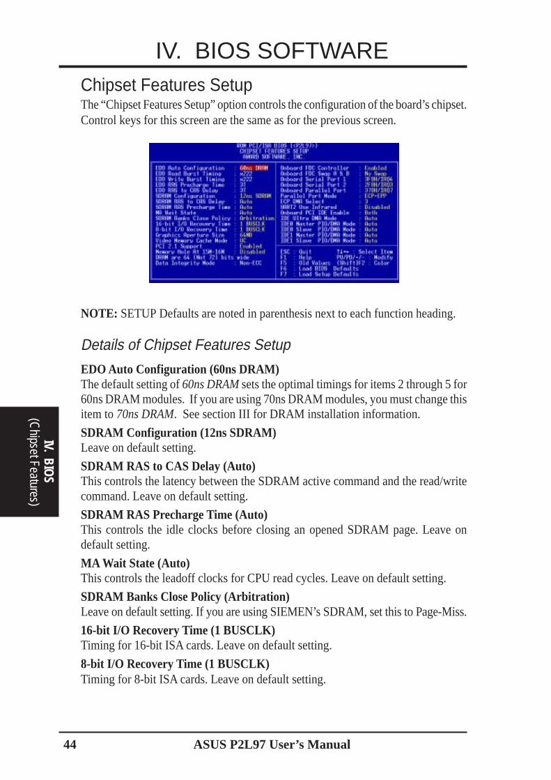
Chipset Features SetupThe “Chipset Features Setup” option controls the configuration of the board’s chipset.Control keys for this screen are the same as for the previous screen.
NOTE: SETUP Defaults are noted in parenthesis next to each function heading.
Details of Chipset Features Setup
EDO Auto Configuration (60ns DRAM)The default setting of 60ns DRAM sets the optimal timings for items 2 through 5 for60ns DRAM modules. If you are using 70ns DRAM modules, you must change thisitem to 70ns DRAM. See section III for DRAM installation information.
SDRAM Configuration (12ns SDRAM)Leave on default setting.
SDRAM RAS to CAS Delay (Auto)This controls the latency between the SDRAM active command and the read/writecommand. Leave on default setting.
SDRAM RAS Precharge Time (Auto)This controls the idle clocks before closing an opened SDRAM page. Leave ondefault setting.
MA Wait State (Auto)This controls the leadoff clocks for CPU read cycles. Leave on default setting.
SDRAM Banks Close Policy (Arbitration)Leave on default setting. If you are using SIEMEN’s SDRAM, set this to Page-Miss.
16-bit I/O Recovery Time (1 BUSCLK)Timing for 16-bit ISA cards. Leave on default setting.
8-bit I/O Recovery Time (1 BUSCLK)Timing for 8-bit ISA cards. Leave on default setting.
ASUS P2L97 User’s Manual 45
IV. BIOS SOFTWARE
IV.
BIO
S(C
hips
et F
eatu
res)
Graphics Aperture Size (64MB)Memory-mapped, graphics data structures can reside in a Graphics Aperture. Leaveon default setting.
Video Memory Cache Mode (UC)USWC (uncacheable, speculative write combining) is a new cache technology forthe video memory of the processor. It can greatly improve the display speed bycaching the display data. You must leave this on the default setting of UC(uncacheable) if your display card cannot support this feature or else your systemmay not boot.
PCI 2.1 Support (Enabled)This function allows you to enable or disable PCI 2.1 features. Leave on Enabledsetting for PCI 2.1 compliancy.
Memory Hole At 15M–16M (Disabled)Enabling this feature reserves 15MB to 16MB memory address space to ISA expan-sion cards that specifically require this setting. This makes the memory from 15MBand up unavailable to the system. Expansion cards can only access memory up to16MB. The default is Disabled.
DRAM are xx bits wideIf all your DIMMs have ECC (e.g., 8 chips + 1 parity chip), they are considered72bits. This motherboard sums the memory per bank and therefore two moduleswill give 72bits and the following will be displayed:
If your DIMMs do not have ECC (e.g. 8 chips), they are considered 64bits and thefollowing will be displayed instead:
Data Integrity Mode (Non-ECC)Non-ECC has byte-wise write capability but no provision for protecting data integ-rity in the DRAM array. EC-Only data errors are detected but not corrected. ECCallows a detection of single-bit and multiple-bit errors and recovery of single-biterrors. (See section III for more information on DRAM memory modules.)....................................................................................................................................
Onboard FDC Controller (Enabled)When Enabled, this field allows you to connect your floppy disk drives to the onboardfloppy disk drive connector instead of a separate controller card. If you want to use adifferent controller card to connect the floppy disk drives, set this field to Disabled.

ASUS P2L97 User’s Manual46
IV. BIOS SOFTWAREOnboard FDC Swap A & B (No Swap)This field allows you to reverse the hardware drive letter assignments of your floppydisk drives. Two options are available: No Swap and Swap AB. If you want to switchdrive letter assignments through the onboard chipset, set this field to Swap AB.Onboard Serial Port 1 (3F8H/IRQ4)Settings are 3F8H/IRQ4, 2F8H/IRQ3, 3E8H/IRQ4, 2E8H/IRQ10, and Disabled forthe onboard serial connector.Onboard Serial Port 2 (2F8H/IRQ3)Settings are 3F8H/IRQ4, 2F8H/IRQ3, 3E8H/IRQ4, 2E8H/IRQ10, and Disabled forthe onboard serial connector.Onboard Parallel Port (378H/IRQ7)This field sets the address of the onboard parallel port connector. You can selecteither: 3BCH / IRQ 7, 378H / IRQ 7, 278H / IRQ 5, Disabled. If you install an I/O cardwith a parallel port, ensure that there is no conflict in the address assignments. The PCcan support up to three parallel ports as long as there are no conflicts for each port.Parallel Port Mode (ECP+EPP)This field allows you to set the operation mode of the parallel port. The settingNormal, allows normal-speed operation but in one direction only; EPP allows bidi-rectional parallel port operation at maximum speed; ECP allows the parallel port tooperate in bidirectional mode and at a speed faster than the maximum unidirectionaldata transfer rate; ECP+EPP allows normal speed operation in a two-way mode.ECP DMA Select (3)This selection is available only if you select ECP or ECP+EPP in the Parallel PortMode. Select either DMA Channel 1, 3, or Disable.UART2 Use Infrared (Disabled)When enabled, this field activates the onboard infrared feature and sets the secondserial UART to support the infrared module connector on the motherboard. If yoursystem already has a second serial port connected to the onboard COM2 connector, itwill no longer work if you enable the infrared feature. By default, this field is set toDisabled, which leaves the second serial port UART to support the COM2 serial portconnector. See IrDA-compliant infrared module connector under section III.Onboard PCI IDE Enable (Both)You can select to enable the primary IDE channel, secondary IDE channel, both, ordisable both channels (for systems with only SCSI drives).IDE Ultra DMA Mode (Auto)This sets the IDE UltraDMA to be active when using UltraDMA-capable IDE de-vices. The BIOS will automatically adjust or disable this setting for slower IDEdevices so that Auto or high settings will not cause problems for older IDE devices.Choose Disable if you do not want this feature for all devices.IDE 0 Master/Slave PIO/DMA Mode, IDE 1 Master/Slave PIO/DMA Mode (Auto)Each channel (0 and 1) has both a master and a slave making four IDE devicespossible. Because each IDE device may have a different Mode timing (0, 1, 2, 3, 4),it is necessary for these to be independent. The default setting of Auto will allowauto-detection to ensure optimal performance.
IV. BIOS
(Chipset Features)
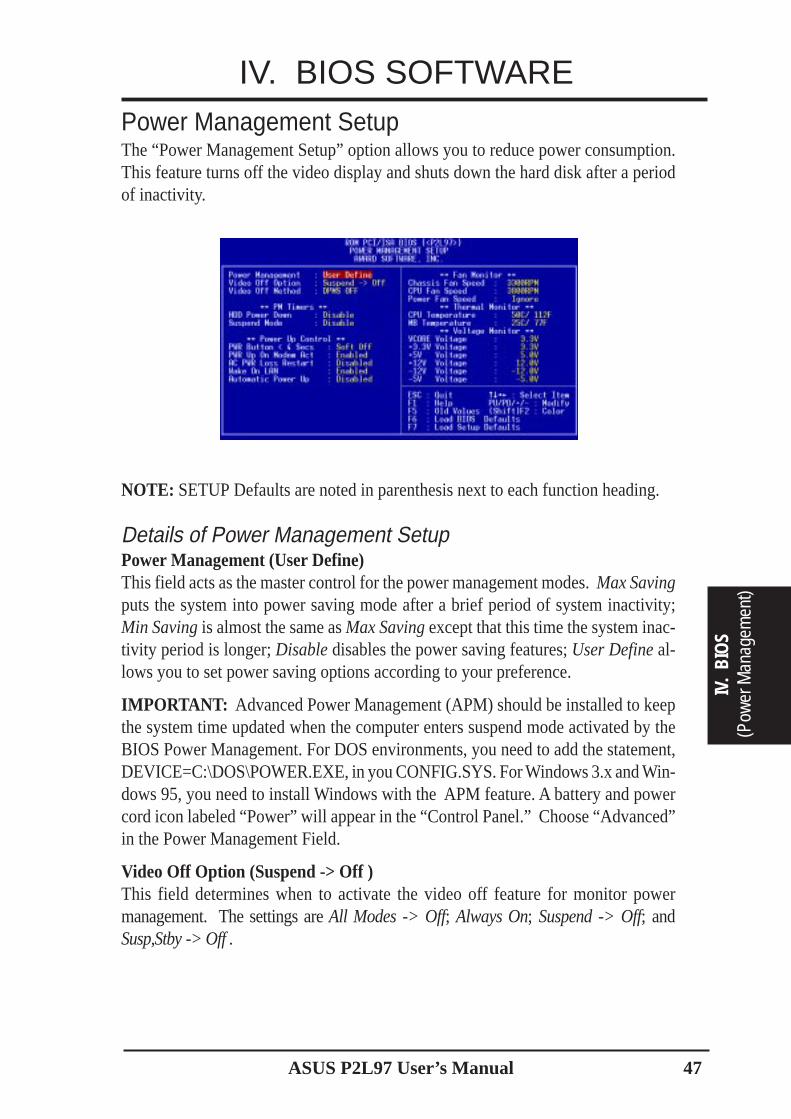
ASUS P2L97 User’s Manual 47
IV. BIOS SOFTWARE
IV.
BIO
S(P
ower
Man
agem
ent)
Power Management SetupThe “Power Management Setup” option allows you to reduce power consumption.This feature turns off the video display and shuts down the hard disk after a periodof inactivity.
NOTE: SETUP Defaults are noted in parenthesis next to each function heading.
Details of Power Management SetupPower Management (User Define)This field acts as the master control for the power management modes. Max Savingputs the system into power saving mode after a brief period of system inactivity;Min Saving is almost the same as Max Saving except that this time the system inac-tivity period is longer; Disable disables the power saving features; User Define al-lows you to set power saving options according to your preference.
IMPORTANT: Advanced Power Management (APM) should be installed to keepthe system time updated when the computer enters suspend mode activated by theBIOS Power Management. For DOS environments, you need to add the statement,DEVICE=C:\DOS\POWER.EXE, in you CONFIG.SYS. For Windows 3.x and Win-dows 95, you need to install Windows with the APM feature. A battery and powercord icon labeled “Power” will appear in the “Control Panel.” Choose “Advanced”in the Power Management Field.
Video Off Option (Suspend -> Off )This field determines when to activate the video off feature for monitor powermanagement. The settings are All Modes -> Off; Always On; Suspend -> Off; andSusp,Stby -> Off .
ASUS P2L97 User’s Manual48
IV. BIOS SOFTWARE
IV. BIOS
(Power M
anagement)
Video Off Method (DPMS OFF)This field defines the video off features. The following options are available: DPMSOFF, DPMS Reduce ON, Blank Screen, V/H SYNC+Blank, DPMS Standby, andDPMS Suspend. The DPMS (Display Power Management System) features allowthe BIOS to control the video display card if it supports the DPMS feature. BlankScreen only blanks the screen (use this for monitors without power management or“green” features. If set up in your system, your screen saver will not display withBlank Screen selected). V/H SYNC+Blank blanks the screen and turns off verticaland horizontal scanning........................................................................................................................................
PM TimersThis section controls the time-out settings for the Power Management scheme. Thefields included in this section are “HDD Power Down”, which places the hard diskinto its lowest power consumption mode, and the Suspend mode which suspends theCPU.
The system automatically “wakes up” from any power saving mode when there issystem activity such as when a key is pressed from the keyboard, or when there isactivity detected from the enabled IRQ channels.
HDD Power Down (Disable)Shuts down any IDE hard disk drives in the system after a period of inactivity. Thistime period is user-configurable to 1–15 Min or Disable. This feature does notaffect SCSI hard drives.
Suspend Mode (Disable)Sets the period of time after which each of these modes activate: 1 Min, 2 Min, 4Min, 8 Min, 10 Min, 20 Min, 30 Min, 1 Hour, 2 Hour, and 4 Hour........................................................................................................................................
Power Up ControlThis section determines the ways the system can be controlled when it is started orrestarted, when modem activity is detected, or when power to the computer is inter-rupted and reapplied. The Soft-Off mode refers to powering off the system througha momentary button switch (ATX switch) or through the software as opposed todisconnecting the AC power by way of a rocker switch or other means.
PWR Button < 4 Secs (Soft Off)When set to Soft Off, the ATX switch can be used as a normal system power-offbutton when pressed for less than 4 seconds. Suspend allows the button to have adual function where pressing less than 4 seconds will place the system in sleepmode. Regardless of the setting, holding the ATX switch for more than 4 secondswill power off the system.

ASUS P2L97 User’s Manual 49
IV. BIOS SOFTWARE
IV.
BIO
S(P
ower
Man
agem
ent)
PWR Up On Modem Act (Enabled)This allows either settings of Enabled or Disabled for powering up the computer(turns the ATX power supply on) when the modem receives a call while the com-puter is off. NOTE: The computer cannot receive or transmit data until the com-puter and applications are fully running, thus connection cannot be made on the firsttry. Turning an external modem off and then back on while the computer is offcauses an initialization string that will also cause the system to power on.
AC PWR Loss Restart (Disabled)This allows you to set whether you want your system to boot up after the power hasbeen interrupted. Disabled leaves your system off after reapplying power and En-abled boots up your system after reapplying power.
Wake On LAN (Enabled)Enable allows the ASUS PCI-L101 fast Ethernet card to power up the system usingthe proper software. Disable turns off this feature.
Automatic Power Up (Disabled)This allows you to have an unattended or automatic power up of your system. You mayconfigure your system to power up at a certain time of the day by selecting Everyday,which will allow you to set the time or at a certain time and day by selecting By Date......................................................................................................................................
Fan Monitor (xxxxRPM)The onboard hardware monitor is able to detect the Chassis Fan Speed, CPU FanSpeed, and the Power Supply Fan Speed in Rotations Per Minute (RPM). Set toIgnore if one of these are not used so that error messages will not be given......................................................................................................................................
Thermal Monitor (xxxC/xxxF)The onboard hardware monitor is able to detect the CPU (thermal-sensing heatsinkrequired for Pentium II processor) and MB (motherboard) temperatures. Set to Ig-nore if unavailable......................................................................................................................................
Voltage Monitor (xx.xV)The onboard hardware monitor is able to detect the voltages put out by the voltageregulators. Set to Ignore if unavailable.
NOTE: If any of the monitored items are out of range, an error message will appear:“Hardware Monitor found an error, enter POWER MANAGEMENT SETUP fordetails”. You will then be prompted to “Press F1 to continue, DEL to enter SETUP”.
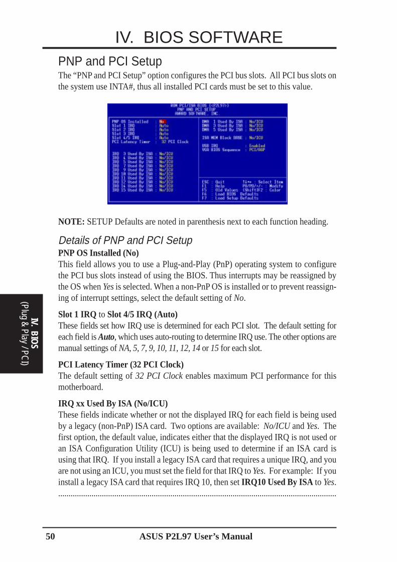
ASUS P2L97 User’s Manual50
IV. BIOS SOFTWARE
(Plug & Play / PCI)
IV. BIOS
PNP and PCI SetupThe “PNP and PCI Setup” option configures the PCI bus slots. All PCI bus slots onthe system use INTA#, thus all installed PCI cards must be set to this value.
NOTE: SETUP Defaults are noted in parenthesis next to each function heading.
Details of PNP and PCI SetupPNP OS Installed (No)This field allows you to use a Plug-and-Play (PnP) operating system to configurethe PCI bus slots instead of using the BIOS. Thus interrupts may be reassigned bythe OS when Yes is selected. When a non-PnP OS is installed or to prevent reassign-ing of interrupt settings, select the default setting of No.
Slot 1 IRQ to Slot 4/5 IRQ (Auto)These fields set how IRQ use is determined for each PCI slot. The default setting foreach field is Auto, which uses auto-routing to determine IRQ use. The other options aremanual settings of NA, 5, 7, 9, 10, 11, 12, 14 or 15 for each slot.
PCI Latency Timer (32 PCI Clock)The default setting of 32 PCI Clock enables maximum PCI performance for thismotherboard.
IRQ xx Used By ISA (No/ICU)These fields indicate whether or not the displayed IRQ for each field is being usedby a legacy (non-PnP) ISA card. Two options are available: No/ICU and Yes. Thefirst option, the default value, indicates either that the displayed IRQ is not used oran ISA Configuration Utility (ICU) is being used to determine if an ISA card isusing that IRQ. If you install a legacy ISA card that requires a unique IRQ, and youare not using an ICU, you must set the field for that IRQ to Yes. For example: If youinstall a legacy ISA card that requires IRQ 10, then set IRQ10 Used By ISA to Yes.......................................................................................................................................
ASUS P2L97 User’s Manual 51
IV. BIOS SOFTWARE
IV.
BIO
S(P
lug
& Pl
ay /
PCI)
DMA x Used By ISA (No/ICU)These fields indicate whether or not the displayed DMA channel for each field isbeing used by a legacy (non-PnP) ISA card. Available options include: No/ICU andYes. The first option, the default setting, indicates either that the displayed DMAchannel is not used or an ICU is being used to determine if an ISA card is using thatchannel. If you install a legacy ISA card that requires a unique DMA channel, andyou are not using an ICU, you must set the field for that channel to Yes.
ISA MEM Block BASE (No/ICU)This field allows you to set the base address and block size of a legacy ISA card thatuses any memory segment within the C800H and DFFFH address range. If youhave such a card, and you are not using an ICU to specify its address range, select abase address from the six available options; the ISA MEM Block SIZE field willthen appear for selecting the block size. If you have more than one legacy ISA cardin your system that requires to use this address range, you can increase the blocksize to either 8K, 16K, 32K, or 64K. If you are using an ICU to accomplish this task,leave ISA MEM Block BASE to its default setting of No/ICU.
USB IRQ (Enabled)Enabled reserves an IRQ# for the USB to work, Disabled does not allow the USB tohave an IRQ# and therefore prevents the USB from functioning. If you do not useUSB devices, you may Disable this feature to save an extra IRQ# for expansion cards.
VGA BIOS Sequence (PCI/AGP)If your computer has both PCI and AGP VGA cards, this field allows you to selectwhich of the cards will act as your primary card. The default, PCI/AGP, allows yourPCI card to take precedent when detected. AGP/PCI uses the AGP card as yourprimary card.
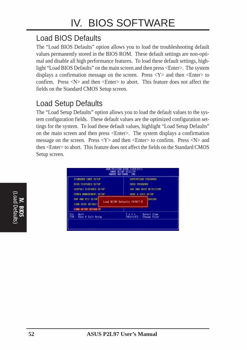
ASUS P2L97 User’s Manual52
IV. BIOS SOFTWARE
(Load Defaults)
IV. BIOS
Load BIOS DefaultsThe “Load BIOS Defaults” option allows you to load the troubleshooting defaultvalues permanently stored in the BIOS ROM. These default settings are non-opti-mal and disable all high performance features. To load these default settings, high-light “Load BIOS Defaults” on the main screen and then press <Enter>. The systemdisplays a confirmation message on the screen. Press <Y> and then <Enter> toconfirm. Press <N> and then <Enter> to abort. This feature does not affect thefields on the Standard CMOS Setup screen.
Load Setup DefaultsThe “Load Setup Defaults” option allows you to load the default values to the sys-tem configuration fields. These default values are the optimized configuration set-tings for the system. To load these default values, highlight “Load Setup Defaults”on the main screen and then press <Enter>. The system displays a confirmationmessage on the screen. Press <Y> and then <Enter> to confirm. Press <N> andthen <Enter> to abort. This feature does not affect the fields on the Standard CMOSSetup screen.
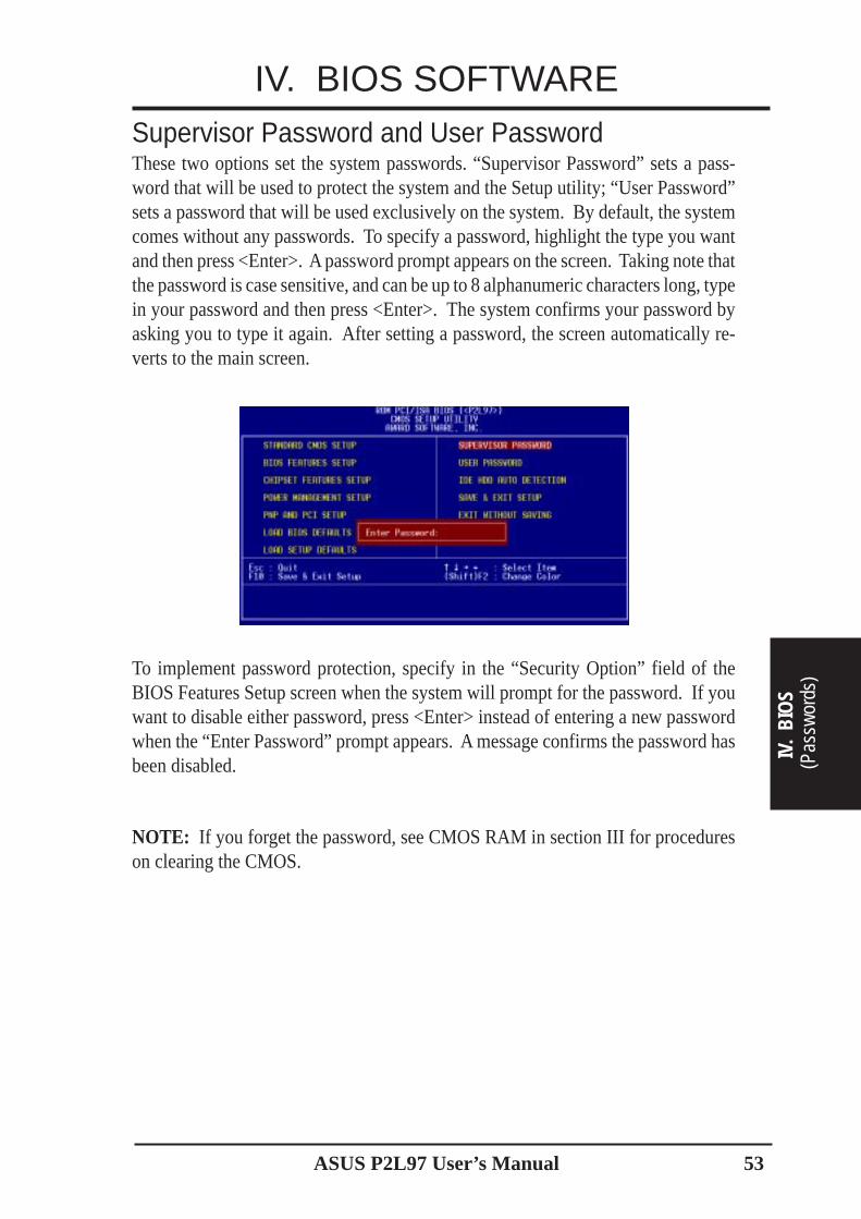
ASUS P2L97 User’s Manual 53
IV. BIOS SOFTWARESupervisor Password and User PasswordThese two options set the system passwords. “Supervisor Password” sets a pass-word that will be used to protect the system and the Setup utility; “User Password”sets a password that will be used exclusively on the system. By default, the systemcomes without any passwords. To specify a password, highlight the type you wantand then press <Enter>. A password prompt appears on the screen. Taking note thatthe password is case sensitive, and can be up to 8 alphanumeric characters long, typein your password and then press <Enter>. The system confirms your password byasking you to type it again. After setting a password, the screen automatically re-verts to the main screen.
To implement password protection, specify in the “Security Option” field of theBIOS Features Setup screen when the system will prompt for the password. If youwant to disable either password, press <Enter> instead of entering a new passwordwhen the “Enter Password” prompt appears. A message confirms the password hasbeen disabled.
NOTE: If you forget the password, see CMOS RAM in section III for procedureson clearing the CMOS.
IV.
BIO
S(P
assw
ords
)
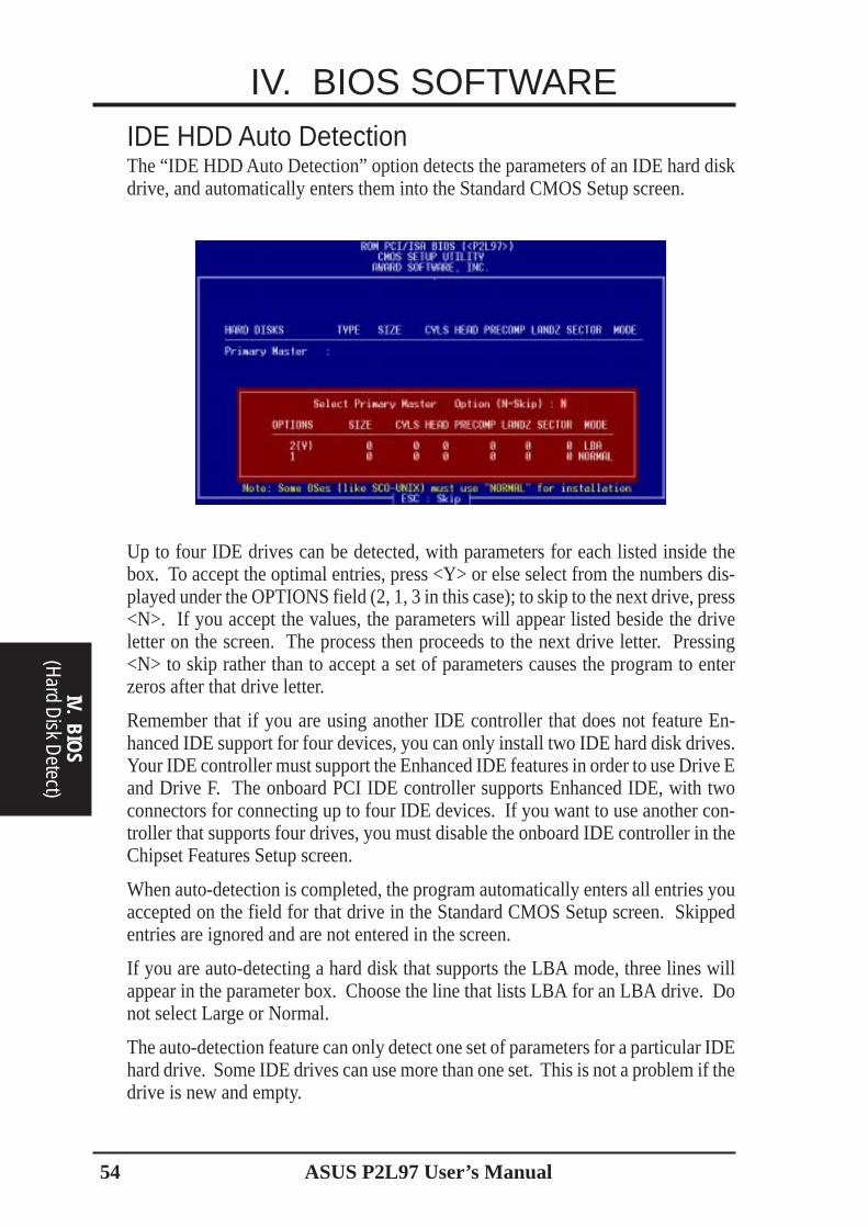
ASUS P2L97 User’s Manual54
IV. BIOS SOFTWARE
IV. BIOS
(Hard D
isk Detect)
IDE HDD Auto DetectionThe “IDE HDD Auto Detection” option detects the parameters of an IDE hard diskdrive, and automatically enters them into the Standard CMOS Setup screen.
Up to four IDE drives can be detected, with parameters for each listed inside thebox. To accept the optimal entries, press <Y> or else select from the numbers dis-played under the OPTIONS field (2, 1, 3 in this case); to skip to the next drive, press<N>. If you accept the values, the parameters will appear listed beside the driveletter on the screen. The process then proceeds to the next drive letter. Pressing<N> to skip rather than to accept a set of parameters causes the program to enterzeros after that drive letter.
Remember that if you are using another IDE controller that does not feature En-hanced IDE support for four devices, you can only install two IDE hard disk drives.Your IDE controller must support the Enhanced IDE features in order to use Drive Eand Drive F. The onboard PCI IDE controller supports Enhanced IDE, with twoconnectors for connecting up to four IDE devices. If you want to use another con-troller that supports four drives, you must disable the onboard IDE controller in theChipset Features Setup screen.
When auto-detection is completed, the program automatically enters all entries youaccepted on the field for that drive in the Standard CMOS Setup screen. Skippedentries are ignored and are not entered in the screen.
If you are auto-detecting a hard disk that supports the LBA mode, three lines willappear in the parameter box. Choose the line that lists LBA for an LBA drive. Donot select Large or Normal.
The auto-detection feature can only detect one set of parameters for a particular IDEhard drive. Some IDE drives can use more than one set. This is not a problem if thedrive is new and empty.
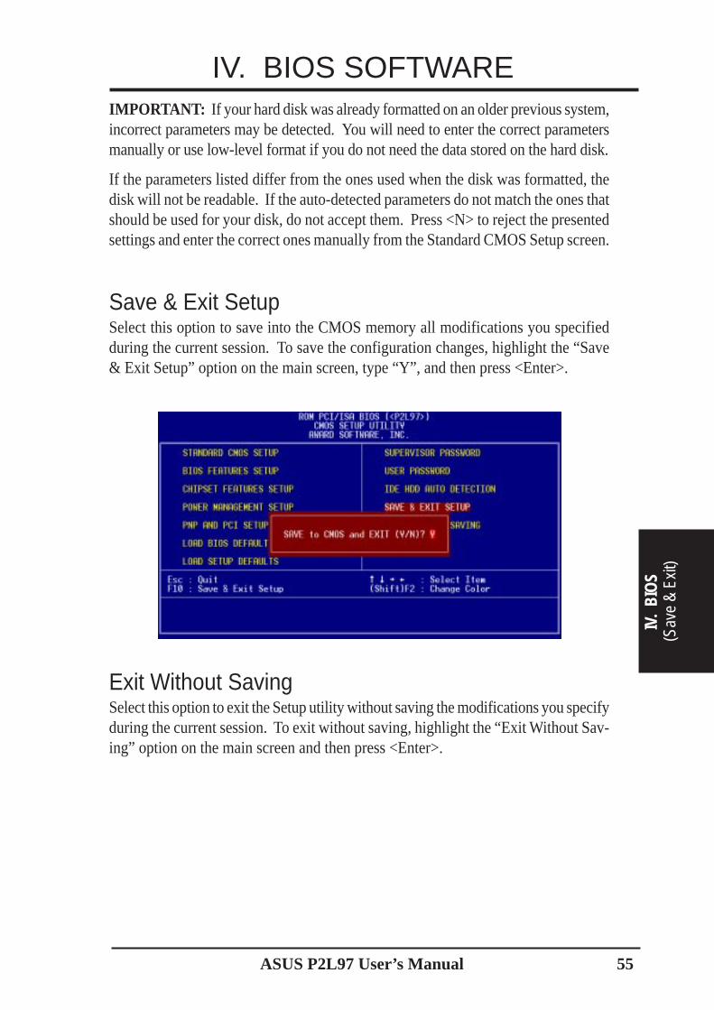
ASUS P2L97 User’s Manual 55
IMPORTANT: If your hard disk was already formatted on an older previous system,incorrect parameters may be detected. You will need to enter the correct parametersmanually or use low-level format if you do not need the data stored on the hard disk.
If the parameters listed differ from the ones used when the disk was formatted, thedisk will not be readable. If the auto-detected parameters do not match the ones thatshould be used for your disk, do not accept them. Press <N> to reject the presentedsettings and enter the correct ones manually from the Standard CMOS Setup screen.
Save & Exit SetupSelect this option to save into the CMOS memory all modifications you specifiedduring the current session. To save the configuration changes, highlight the “Save& Exit Setup” option on the main screen, type “Y”, and then press <Enter>.
Exit Without SavingSelect this option to exit the Setup utility without saving the modifications you specifyduring the current session. To exit without saving, highlight the “Exit Without Sav-ing” option on the main screen and then press <Enter>.
IV. BIOS SOFTWARE
IV.
BIO
S(S
ave
& Ex
it)
ASUS P2L97 User’s Manual56
(This page was intentionally left blank)
○ ○ ○ ○ ○ ○ ○ ○ ○ ○ ○ ○ ○ ○ ○ ○ ○ ○ ○ ○ ○ ○ ○ ○ ○ ○ ○ ○ ○ ○ ○ ○ ○ ○ ○ ○ ○
○ ○ ○ ○ ○ ○ ○ ○ ○ ○ ○ ○ ○ ○ ○ ○ ○ ○ ○ ○ ○ ○ ○ ○ ○ ○ ○ ○ ○ ○ ○ ○ ○ ○ ○ ○ ○
○ ○ ○ ○ ○ ○ ○ ○ ○ ○ ○ ○ ○ ○ ○ ○ ○ ○ ○ ○ ○ ○ ○ ○ ○ ○ ○ ○ ○ ○ ○ ○ ○ ○ ○ ○ ○
○ ○ ○ ○ ○ ○ ○ ○ ○ ○ ○ ○ ○ ○ ○ ○ ○ ○ ○ ○ ○ ○ ○ ○ ○ ○ ○ ○ ○ ○ ○ ○ ○ ○ ○ ○ ○
○ ○ ○ ○ ○ ○ ○ ○ ○ ○ ○ ○ ○ ○ ○ ○ ○ ○ ○ ○ ○ ○ ○ ○ ○ ○ ○ ○ ○ ○ ○ ○ ○ ○ ○ ○ ○
○ ○ ○ ○ ○ ○ ○ ○ ○ ○ ○ ○ ○ ○ ○ ○ ○ ○ ○ ○ ○ ○ ○ ○ ○ ○ ○ ○ ○ ○ ○ ○ ○ ○ ○ ○ ○
○ ○ ○ ○ ○ ○ ○ ○ ○ ○ ○ ○ ○ ○ ○ ○ ○ ○ ○ ○ ○ ○ ○ ○ ○ ○ ○ ○ ○ ○ ○ ○ ○ ○ ○ ○ ○
○ ○ ○ ○ ○ ○ ○ ○ ○ ○ ○ ○ ○ ○ ○ ○ ○ ○ ○ ○ ○ ○ ○ ○ ○ ○ ○ ○ ○ ○ ○ ○ ○ ○ ○ ○ ○
○ ○ ○ ○ ○ ○ ○ ○ ○ ○ ○ ○ ○ ○ ○ ○ ○ ○ ○ ○ ○ ○ ○ ○ ○ ○ ○ ○ ○ ○ ○ ○ ○ ○ ○ ○ ○
○ ○ ○ ○ ○ ○ ○ ○ ○ ○ ○ ○ ○ ○ ○ ○ ○ ○ ○ ○ ○ ○ ○ ○ ○ ○ ○ ○ ○ ○ ○ ○ ○ ○ ○ ○ ○
○ ○ ○ ○ ○ ○ ○ ○ ○ ○ ○ ○ ○ ○ ○ ○ ○ ○ ○ ○ ○ ○ ○ ○ ○ ○ ○ ○ ○ ○ ○ ○ ○ ○ ○ ○ ○
○ ○ ○ ○ ○ ○ ○ ○ ○ ○ ○ ○ ○ ○ ○ ○ ○ ○ ○ ○ ○ ○ ○ ○ ○ ○ ○ ○ ○ ○ ○ ○ ○ ○ ○ ○ ○
○ ○ ○ ○ ○ ○ ○ ○ ○ ○ ○ ○ ○ ○ ○ ○ ○ ○ ○ ○ ○ ○ ○ ○ ○ ○ ○ ○ ○ ○ ○ ○ ○ ○ ○ ○ ○
○ ○ ○ ○ ○ ○ ○ ○ ○ ○ ○ ○ ○ ○ ○ ○ ○ ○ ○ ○ ○ ○ ○ ○ ○ ○ ○ ○ ○ ○ ○ ○ ○ ○ ○ ○ ○
○ ○ ○ ○ ○ ○ ○ ○ ○ ○ ○ ○ ○ ○ ○ ○ ○ ○ ○ ○ ○ ○ ○ ○ ○ ○ ○ ○ ○ ○ ○ ○ ○ ○ ○ ○ ○
○ ○ ○ ○ ○ ○ ○ ○ ○ ○ ○ ○ ○ ○ ○ ○ ○ ○ ○ ○ ○ ○ ○ ○ ○ ○ ○ ○ ○ ○ ○ ○ ○ ○ ○ ○ ○
○ ○ ○ ○ ○ ○ ○ ○ ○ ○ ○ ○ ○ ○ ○ ○ ○ ○ ○ ○ ○ ○ ○ ○ ○ ○ ○ ○ ○ ○ ○ ○ ○ ○ ○ ○ ○
○ ○ ○ ○ ○ ○ ○ ○ ○ ○ ○ ○ ○ ○ ○ ○ ○ ○ ○ ○ ○ ○ ○ ○ ○ ○ ○ ○ ○ ○ ○ ○ ○ ○ ○ ○ ○
○ ○ ○ ○ ○ ○ ○ ○ ○ ○ ○ ○ ○ ○ ○ ○ ○ ○ ○ ○ ○ ○ ○ ○ ○ ○ ○ ○ ○ ○ ○ ○ ○ ○ ○ ○ ○
○ ○ ○ ○ ○ ○ ○ ○ ○ ○ ○ ○ ○ ○ ○ ○ ○ ○ ○ ○ ○ ○ ○ ○ ○ ○ ○ ○ ○ ○ ○ ○ ○ ○ ○ ○ ○
○ ○ ○ ○ ○ ○ ○ ○ ○ ○ ○ ○ ○ ○ ○ ○ ○ ○ ○ ○ ○ ○ ○ ○ ○ ○ ○ ○ ○ ○ ○ ○ ○ ○ ○ ○ ○
○ ○ ○ ○ ○ ○ ○ ○ ○ ○ ○ ○ ○ ○ ○ ○ ○ ○ ○ ○ ○ ○ ○ ○ ○ ○ ○ ○ ○ ○ ○ ○ ○ ○ ○ ○ ○
○ ○ ○ ○ ○ ○ ○ ○ ○ ○ ○ ○ ○ ○ ○ ○ ○ ○ ○ ○ ○ ○ ○ ○ ○ ○ ○ ○ ○ ○ ○ ○ ○ ○ ○ ○ ○
○ ○ ○ ○ ○ ○ ○ ○ ○ ○ ○ ○ ○ ○ ○ ○ ○ ○ ○ ○ ○ ○ ○ ○ ○ ○ ○ ○ ○ ○ ○ ○ ○ ○ ○ ○ ○
○ ○ ○ ○ ○ ○ ○ ○ ○ ○ ○ ○ ○ ○ ○ ○ ○ ○ ○ ○ ○ ○ ○ ○ ○ ○ ○ ○ ○ ○ ○ ○ ○ ○ ○ ○ ○
○ ○ ○ ○ ○ ○ ○ ○ ○ ○ ○ ○ ○ ○ ○ ○ ○ ○ ○ ○ ○ ○ ○ ○ ○ ○ ○ ○ ○ ○ ○ ○ ○ ○ ○ ○ ○
○ ○ ○ ○ ○ ○ ○ ○ ○ ○ ○ ○ ○ ○ ○ ○ ○ ○ ○ ○ ○ ○ ○ ○ ○ ○ ○ ○ ○ ○ ○ ○ ○ ○ ○ ○ ○
○ ○ ○ ○ ○ ○ ○ ○ ○ ○ ○ ○ ○ ○ ○ ○ ○ ○ ○ ○ ○ ○ ○ ○ ○ ○ ○ ○ ○ ○ ○ ○ ○ ○ ○ ○ ○
○ ○ ○ ○ ○ ○ ○ ○ ○ ○ ○ ○ ○ ○ ○ ○ ○ ○ ○ ○ ○ ○ ○ ○ ○ ○ ○ ○ ○ ○ ○ ○ ○ ○ ○ ○ ○
○ ○ ○ ○ ○ ○ ○ ○ ○ ○ ○ ○ ○ ○ ○ ○ ○ ○ ○ ○ ○ ○ ○ ○ ○ ○ ○ ○ ○ ○ ○ ○ ○ ○ ○ ○ ○
○ ○ ○ ○ ○ ○ ○ ○ ○ ○ ○ ○ ○ ○ ○ ○ ○ ○ ○ ○ ○ ○ ○ ○ ○ ○ ○ ○ ○ ○ ○ ○ ○ ○ ○ ○ ○
○ ○ ○ ○ ○ ○ ○ ○ ○ ○ ○ ○ ○ ○ ○ ○ ○ ○ ○ ○ ○ ○ ○ ○ ○ ○ ○ ○ ○ ○ ○ ○ ○ ○ ○ ○ ○
○ ○ ○ ○ ○ ○ ○ ○ ○ ○ ○ ○ ○ ○ ○ ○ ○ ○ ○ ○ ○ ○ ○ ○ ○ ○ ○ ○ ○ ○ ○ ○ ○ ○ ○ ○ ○
○ ○ ○ ○ ○ ○ ○ ○ ○ ○ ○ ○ ○ ○ ○ ○ ○ ○ ○ ○ ○ ○ ○ ○ ○ ○ ○ ○ ○ ○ ○ ○ ○ ○ ○ ○ ○
○ ○ ○ ○ ○ ○ ○ ○ ○ ○ ○ ○ ○ ○ ○ ○ ○ ○ ○ ○ ○ ○ ○ ○ ○ ○ ○ ○ ○ ○ ○ ○ ○ ○ ○ ○ ○
○ ○ ○ ○ ○ ○ ○ ○ ○ ○ ○ ○ ○ ○ ○ ○ ○ ○ ○ ○ ○ ○ ○ ○ ○ ○ ○ ○ ○ ○ ○ ○ ○ ○ ○ ○ ○
○ ○ ○ ○ ○ ○ ○ ○ ○ ○ ○ ○ ○ ○ ○ ○ ○ ○ ○ ○ ○ ○ ○ ○ ○ ○ ○ ○ ○ ○ ○ ○ ○ ○ ○ ○ ○
○ ○ ○ ○ ○ ○ ○ ○ ○ ○ ○ ○ ○ ○ ○ ○ ○ ○ ○ ○ ○ ○ ○ ○ ○ ○ ○ ○ ○ ○ ○ ○ ○ ○ ○ ○ ○
○ ○ ○ ○ ○ ○ ○ ○ ○ ○ ○ ○ ○ ○ ○ ○ ○ ○ ○ ○ ○ ○ ○ ○ ○ ○ ○ ○ ○ ○ ○ ○ ○ ○ ○ ○ ○
○ ○ ○ ○ ○ ○ ○ ○ ○ ○ ○ ○ ○ ○ ○ ○ ○ ○ ○ ○ ○ ○ ○ ○ ○ ○ ○ ○ ○ ○ ○ ○ ○ ○ ○ ○ ○
○ ○ ○ ○ ○ ○ ○ ○ ○ ○ ○ ○ ○ ○ ○ ○ ○ ○ ○ ○ ○ ○ ○ ○ ○ ○ ○ ○ ○ ○ ○ ○ ○ ○ ○ ○ ○
○ ○ ○ ○ ○ ○ ○ ○ ○ ○ ○ ○ ○ ○ ○ ○ ○ ○ ○ ○ ○ ○ ○ ○ ○ ○ ○ ○ ○ ○ ○ ○ ○ ○ ○ ○ ○
○ ○ ○ ○ ○ ○ ○ ○ ○ ○ ○ ○ ○ ○ ○ ○ ○ ○ ○ ○ ○ ○ ○ ○ ○ ○ ○ ○ ○ ○ ○ ○ ○ ○ ○ ○ ○