Embed Size (px)
Citation preview
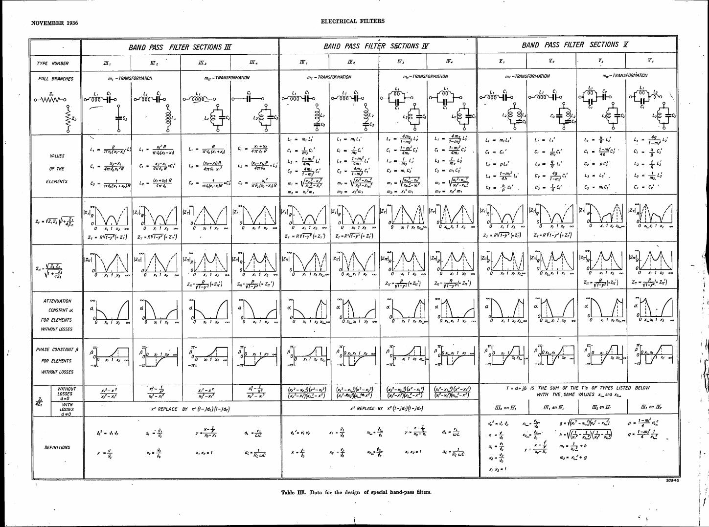
NOVEMBER 1936
ÈLECTRIèAL ,FILTERS .IV.: ".. \ "'\ -. .......
Vacation Course, hel~ àt D~lft, :Ap~if ~?3~.
By BALTH. 'VAN 'DER POL and TH.' J. WEIJERS.'. " .. ~ ~ .... ~ " ....... ;- .....
. ~ " :
'HIGH-PASS AND,B.i\ND7PASS 'FICTER SÉCTIONS :-,,_ .. I.'" ~. • .'. 1 . 1" ~ ~
S~ary: The ~ethod described m: the previous ~riic,le for ~n~~~iigating low-pass" £tlte~ '_ ,'sections (bàsic' typès and. m~trans(o~ma!ions) llFeapplied in, tP,is Il_l"~~iet~ high-pass ~d, " "band-pass :filters.Furthermore, in the section on "double m-transformation" an extension'. .._.. .' --_ ,,' ,'. . '. ., ,. ~.- ...
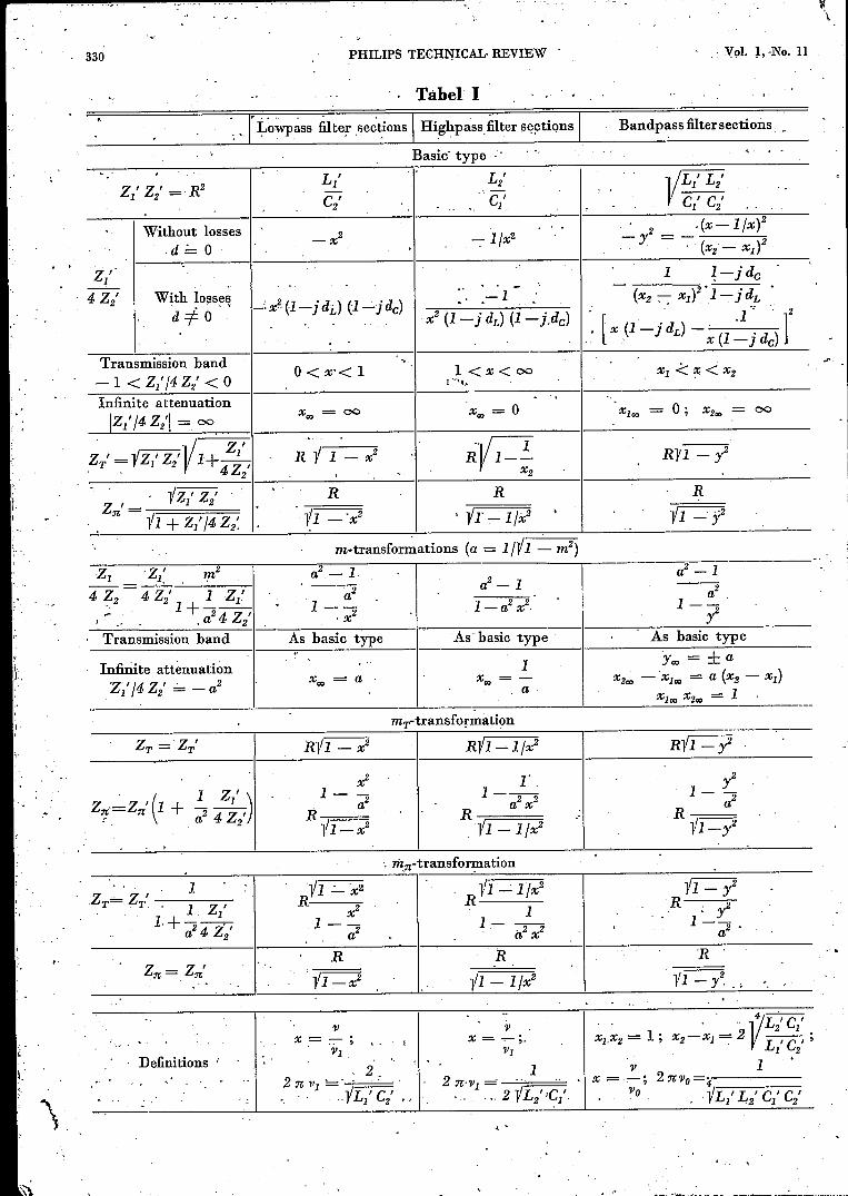
: 'of the m-transformation is givën, which can be applied to band-pass :filtersand, inter. alia,lcan also give rise to sections 'of' a parti~U1ar1ysimple ~onstrUctión;' Alf data obtained in"this way for the design of l~w:pass: high-pass ,and band-pass :filtèr sections áre collated'in Tables Il and Ill. In conclusion, the design of a low'-pass@ter,which'has to meet specific , -: ,requirements is discussed by way of èxámpIe.' "", ',,' . :. '
Basic Types and m-Transformations These considerations als~ sh~w the values whichIn the previous articles it was shown howthe the impedances Z/ and Z/ must have in order to
image imp~4a~lCe!'i,the propagation constant a~d obtain" a hig~-pàss or ~,~~~Çl:p~ss'fiÎt~;. For high-the transmission and attenuation bànds 'for, pass filter. aections- (fig. l8,h.) the transmission bandT-sections; .IT-sections and' half-sections could b'e" r~!lc~cs' from j the freqüèncy 'VI: to 00, a:~d forrepresented as functions' of the impedances Zl ànd Z2' " band-pass '!il~,èr"secti?ns ~,f~~~ PI, to' 'V2' In' the case 'of the "complete branches". of ~ll ~hle~ '~as~ê 'tYP,èJ:J!hère' i~ .a., ~reque~cy 'Vo
Thus the transmission hand is' expressed by t_he' 'f,o~-which .~~~ ,,', . .0. an~i~.:?2',= 09:.. For, low-passcondition that ZI/4 -?2 must lie between ..:.:-1 and O._ ~Itej; _sec~i~ns,_t:.¥s freg:iï~~cy.' is :0 and; for high-
For the low-pass filter sections discussed in t,he pass, filter, se~,ti0!ls ~; .:While. for; ;.l~e, band-passprevious artièle this -condition wa,s: found to' be "fil~e~ sections.it is finite ,àn,V~es,,~eiwèen' 'VI and 'V2•
satisfied for frequencies below a certain limiting The figure shows diagrammatically the variation," • 0',>' 4 , " ~~f.' ,........':;;;,!,I\._ '_,,"~'
frequency 'Vl: This condition may also be derived of the .reactances Zi' apa"';_4 Z/·, as a' function'from the reactance diagrams of the -fundamental of the frequency for- the tKree b~sic types'. The oir-types shown in, fig. 18. ,The transmission band cuits of the complete hr~:iJ:éhès'giving these functionscommences at the frequency 0 :mth Z/ . 'Io and are shown at the side. I~ the cas~ of th~ 'high-pass- 4 Z/ = j 00. Z/ = j w Lj' increases with the filter section Z/ is a capacity C/, and Z/ a self-frequency, -4 Z/ = j 4/w C/ diminishes with inductance L2'. With the band-pass filter sectionincreasing frequenëy; the point of intersection of Z/ is a self-inductance L/ with a condenser C/the two curves determines the limi~ing frequency 'VI' in series, and Z/ is a self-inductance L/ with a
L' c;L~ Cl 0 V, v ~I-o z'
of'O'ó'.ó 0-11--0
~
L~GC;Ol.c' ~L~T2
1
z' 'r: 1,=JW '+JiiCIZ:=jwL\ .; z: 1 1 ' ~o - ,=]WëI C~, 1 Zj=jwL~ zJ- 'r: 1Z2=~ JW .zt''']Wë;
2009.5a) h) c)
Fig. 18. R~aetance diagrams. HeactancesZjfand -4 Z/ for :filters of the hasic type asa flinction of the frequency 'V. a) Low-pass filter, h) High-pass filter, e) Band-pass filter.A filter has ti passhand when - 4 Z/ lies hetween Z/ and the axis. The transmissionhand~ are indicated on the axis hy a thicker stroke. On the left of each diagram, it isindicated how the reaetanoes can he made up from self-inductances and condensers andhow they can he represented analytically as a funcLion of the angular frequency.
327s-'~ :
, '
'~'IPHILlPS TECHNICAL REVIEW Vol. .1, No. 11
. condenser C/ in:parallel, .~here Ll~C/ = L/ C/so 'that the impedance. Z/ becomes infinite at thesame frequency ~o at which the impedance Z/. disappears 1). '
db~'~T-~'_-r-.-.~r-.-.-~-r-r-.~r-~"
1,0 1,2 1,4 (,6
I f~;Io ·'OJ 0,6
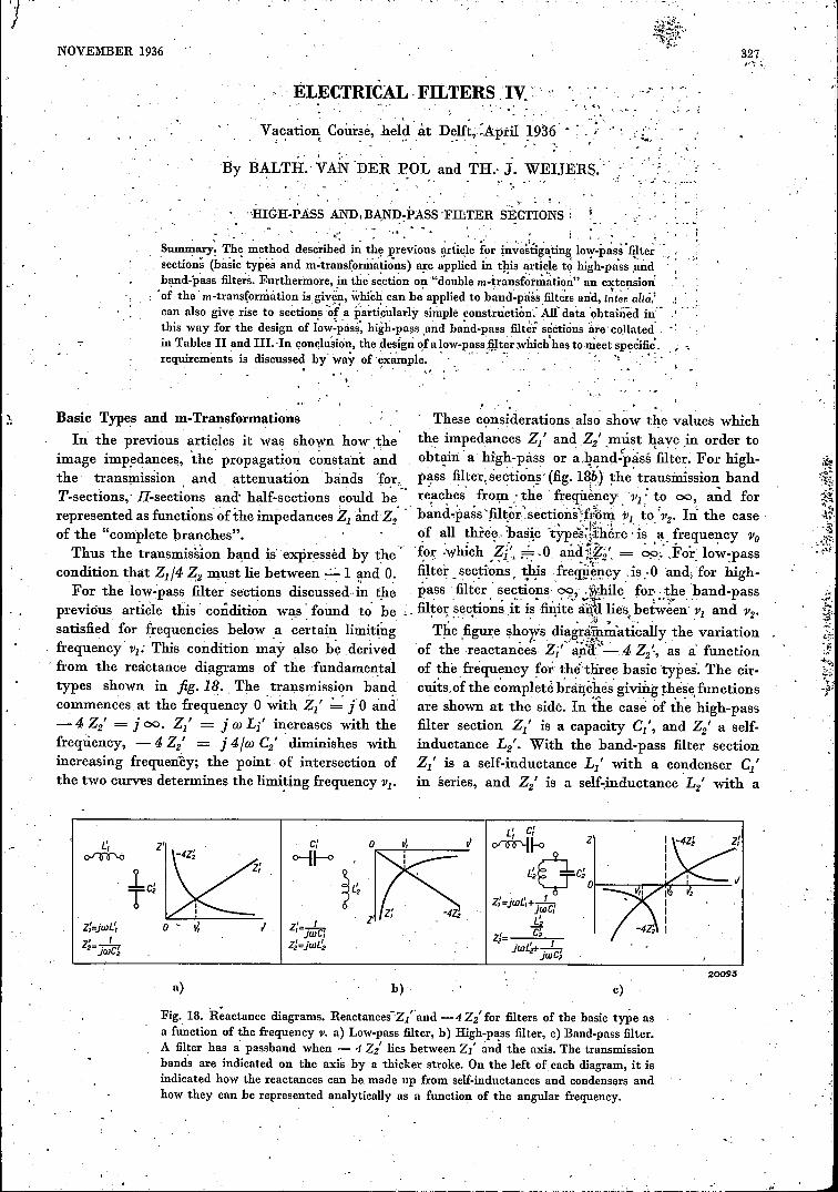
Fig. 19. Att~nuation constant á .(real component of'<thepropagation constant T) in decibels expressed as a functionof IZ1I4 Z21 for T-sections and II sections,
In the previous article (see e.g. P: 305, equation 9,12; 15, 23, 24, 25, 29, 30 and 31) it was shown'that the image impedances and the propagationconstant ~ould be expressed for all sections .(bàsictypes and m-transformations) in terms .of Zl' Z/and Z/ /4 Z/. Now for the low-pass, high-pass andband-pass filter sections of the basic type Z/ Z/has a real, positive value independent of the' fre-.quency, which in conformity with equation (36)in the previous article is 'denoted by R2
• If now 'Zl' /4 Z/ expressed 'as a function of the frequency
. is known .for' an arbitrary filter section of' thebasic type, then: from the equations enumeratedabove the image impedances and the propagationconstant can similarly be obtained as functions of
1) If these frequencies are different, then Z//4 Z/ willchange its sign .between vI and v2' and will therefore notlie wholly between 0 and - 1. Between th~ frequencies, ai whieh Z/ and 22' become zero and infinity respectively,there is an' attenuation band, which interrupts' the trans-mission band. "
dB40
ex36
32
....",
6:;::: ~ ~
~ ~ P""
~ ~,
,
~ v-~ y
/.~~(o~- ~ V =~Oo8 t:
VI/ -/ '/J
1// / < -
v .III
. - .
28
24
20
16
12
8
4
ào 10 12 14 • 16
14~214 6 82
fihl C( (dB)Ili21
rx(dB) 1:&1 cx.(dB) I.20 37,9 50 45,8 200 58,1.
25 39,8 60 47,3 300 61,630 ~1,3 '10 48,8 400 63,8 ,
35 42,'1 80 50,0 500 66,040 43,8 90 51,0 1000 72,1
45 44,8 100 51,9 2000 78,2
20059
Fig. 20. Attenuation constant a in decibels for high valuesof IZI/4 221. For IZ~/4 Z21 < 1.6 fig. 19 is us~d. The tableunder the figure IS a eondnuatlon of the graph for IZI/4 z21> 16.In the latter case the effect of qJ on a can be neglected inpractice.
the frequency (hence also the transmission bandsand the frequencies with infinite attenuation) for.both the basic type and those types obtained after'm-transformation. .
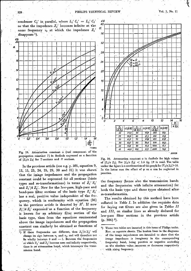
The' results obtained by this method have beencollated in Table I. In addition the requisite datafor laying out filters are also' given in Tables 11and Ill'. on similar lines as already ded~ced forlow-pass filter sections in the previous article(p. 304) 2).
2) These two tables are inserted in this issue of Philips technoRev. as separate sheets. The"broken lines in the diagramsof the image impedances are. intended to show that theimage impedance is imaginary in the correspondingfrequency band, being positive or negative accördingas the absolute' value, increases or decreases respectivelywith rising frequency." .
. ,
"1'..
NOVEMBER 1936 ELECTRICAL FILTERS
All expressions in Table I, with the. exception 3,2
of the third line, apply for' non-dissipative filter 3,sections (d = 0). In the previous article (p. 302) IJ2pa -hrief discussion was given on the effect of the. 2,losses-ill low-pass filtersections. The same remarks 2,also apply to high-pass and band-pass filter sections.
2,The physical interpretation of. the resistance
R = 1'Z/ Z/ was in 'the case of low-pass filter 2,0sections the image impedance:' (both ZT aitd' Z;n) t.at the frequency '!' = 0, and this was in fact true 1,6for both the basic type and the results 'of m-trans- 1,4formation. With high-pass filter, sections R is the 1,2image impedance at the -frequency v ....:..00,. and. 1,0for band-pass fl.lter sections that at the frequency 0,8V - '1'0' the resonance frequency' of the ~wobranches 0,6Z1 and Z2' This frequency '1'0 is the I?-ea~proportion 0,4between the two limiting frequencies VI and '1'2 and
0,2also at. the same time the mean proportion of the 0two frequencies with infinite attenuation Vlco' and 0
'1'200' ,
. One of these frequencies with infinite attenuationcan be chosen arbitrarily, and then determines the~ther frequency with infinite attenuation which liesin the other. attenuation band, as well as theparameter m. In the following section (doublem-transformation] we will ho~ever encow'tter band-pass filter sections, in which the two frequencieswith infinite attenuatio.n can be arbitrarily chosenindependent of, each otherrAs in the c~~e of the low-pass filter sections, so
also with the high-pass and band-pass-filter sections,ZT in .the m;n-transformation and Z;n in themT-transformation are comparatively con,stantthroughout the transmission band, .if m is madeabout 0.6 (see .fig..13 in the previous article). Thusas a rule, here also, half-sections with m equal toapprox. 0.6 can be chosen as terminal half-sections
,in a compound filter.When Z1/4 Z2 has been determined for one filter
section, then figs. 19, 20 and 21 can 'l?e employedto derive the attenuation constant a and the phaseconstant (J by the method discussed in the previousarticle for low-pass filter sections.How a T-section, a lI-section and a half-section
are derived from the full branches given..."in thetables and how, a compound filter can be l;!Uilt upfrom these sections require no further e!ifcidationhere, in view of the full analysis already,;:given.forlow-pass filters.
DoubleSections
In addition to the m-transformations alreadydiscussed, other transformations can also be .
m-Transformations of Band.Pass FilteI:
.1
0.: .. '~ ,,;17500~ ~
I-"
6 / V.......~r-
4 )~
~ '~..~r-- I- i=2I§ v- i""""
......8 l# V
1/V l!!:=/$t,:..-I
I~V j....-- l--_.I~~ ./ V rp...90o
AV V ~ I- I--t:""""
Ar> .j....-- I---.. If/V .. ~-" -,IJV "
IIY -...
f rp_oo,
0,2 0,8 1,0 1,2 1,4 < 1,6
IdLl4Zz :'/765!3
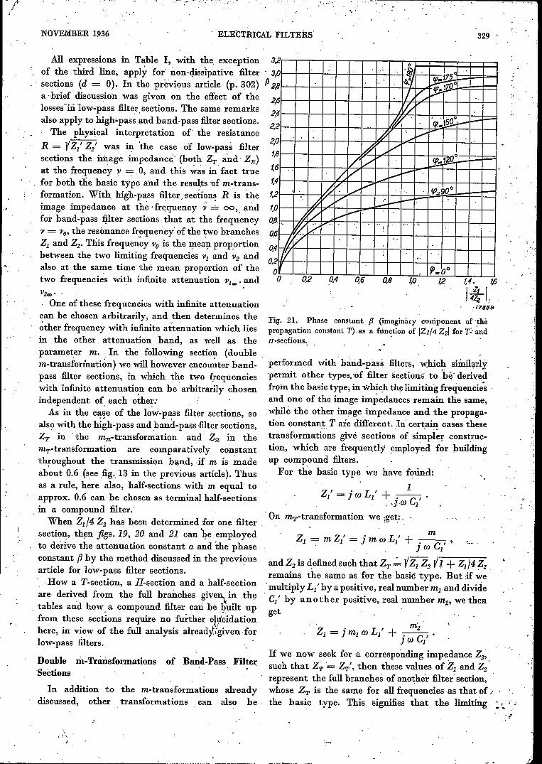
Fig. 21. Phase constant f1 (imaginàry component of 'thèpropagation constant T).as a function of 121/4221 for T~'~nd1I-secfions. .
performed with band-pass filters, which siÎnilarlypermit other' types. 'of' filter sections to 'h~'derivedfrom the basic type, in which the limiting frequencies .and one of the image impedances remain the same,while the other image impedance and the propaga-tion constant T are different ..In certain cases thesetransformations givè sections of simpler construe-tion, which' are frequently employed for buildingup compound filters.For the basic type we have found:
1Z/ = j co L/ + -.---, .
. ' .• l-CO Cl. On mT-trausformation we .get:
mZ1 = m Z/ = j m co L/ + j co C/' '...
and Z2 is defined such that ZT . YZI Z2 Y ~ + ZI/4 Z2remains the same as for the basic type. But if we.multiply LI' by a positive, real number mI and divideC/ by another positive, real number m2' we thenget
If we now seek for a corresponding impedance Z2'such that ZT = ZT', then these values of Zi and Z2represent the full branches of another filter' section,whose ZT is the same for all frequencies as that of "the basic type. This signifies that the limiting
329
.~,;
<.
, .
[.,
~::..... ".'
'f
/
),
330 PHILlPS TECHl'rICAL, REVIEW
Tabel I
.: Vol. :t. ,No. 11
Bandpass filter sectionsLewpass filter .se~~ions Highpassfilter sections
Basic" type "
L/C/
Lz'C/
..Without losses
·d ' 0
.: 2 __ ,(x-l/x)2Y - . ( )2. ' X2 - Xl
Z/4Z/
..With !Oj3S~~
d=fO,-I
Transmission hand 0< X·< 1 l<x<oo- 1< Z/ /4 Zz' < 0 1',,",-. ...
Infinite attenuation x""= 0IZ/ /4 Z/I = 00x""= 00
Z./ = iz/ z/}Il+ Z/, Ril-x2 Rlll 1" 4Z2 X2
Z ,_. iz/ Zz' R R~ 1t - i 1 + Z/ /4 Z2~ il ' 2 , il'-lfx2-x
Rl'1 - iR
m-transfor~ations (a = ldl - m2)
Transmission hand
a2.-1.. 2. a
1--. x2
z, 'Z/-- = --' --'-----4 Z2 4 Zz' 1 Z/'. 1+2--'.' ," ,a 4Z/
a2~1-----
=»I--i
As hasic type As' hasic type As basic type
1Xco =-
aInfinite attenuationZ' '/4 Z' _:_ 21 2 --a
)'''''= ± aX2"" - ·XI"" = a (X2 - Xl)
Xl"" x2., = 1
mT-transformation
RVI i
1 Z/Z_,.' ' Z_' (1 + -2 --)
J~ J. a 4 Z2'
1Z~Z'-----T- . T. 1 Z'
. I1'+-2--'
a 4Z/
. m1t-transfor~ation
R
Definitions ;
i~R .. z. 'Y1-- 2 .a'R .
11 - Y~ .
, . " 4/L 'c 'XI,X2 = 1; XZ-XI , 2V L
2, Cl, ;1 2
V 1X=.-; 2:n;VO='7'4-----
v» . YL/ L/ C/ Cz'
. "
NOVEMBER'1936 ELECTRICAL FILTERS 331
frequencies are also unchanged; for on exceedingthe limiting frequencies, .the image impedanceschange from .a real to an imaginary value' andvice versa. Calculation shows that this impedanceZ2 is of the form shown ~ jig.22; in this fi~'ethe values of the components are also given. It,can also be substituted by the equivalent circuitshown in Table 11; Band-pass filter sections Ill'Usually the latter circuit will be gi~en preference,since the values of the self-inductances and thecondensers are then as a rule neither too large nortoo small, as might frequently happen with thecircuit shown:' in fig. 22. Yet to derive still furtherfilter sections we will for the sake of simplicityemploy the circuit shown in fig. 22. '. The impedance Z2 can only be realised whenmI and m2 satisfy the 'following conditions:
0< m, < 1;0< m2 < 1;X2 mI Xl-~-~-Xl m2 Xz
The sections obtained by "double m-transforma-tion" are compose~ of the same L's and C's as the
L, C,~(--o L,~m,L;
c,=;!;. c;L = 1=ml L'2 4m, ,
C2=~C;'-m2
LJ. _p_ L~m2CJ= ;' cjb _ (X.-!mXI)(X2-.!jJ.: XI)
(X2-XI)'2022/
Fig. 22. Full branches of a band pass filter obtained by doublem-transformation from the basic type. L/, L2',Cl', C2' are thevalues of the components for the basic type, and xj and X2
are the limiting frequencies (see Table H, column 11).
band-pass filter sections 12 obtained by simplem-transformation, although X = 1 is now no longervalid 'for the resonance. frequencies of the twobranches and the ~wo frequencies with infiniteattenuation Xloo and, X200 are no longer inter-relatedby the èquation Xloo • X200 = 1. By a suitable valueof mI and m2' Xloo and X200 ~an be arbitrazily chosenindependent of each other, provided a frequenèywith infinite attenuation is located in each attenu-ation band.A double m-transformation may he performed on
exactly the same lines on the basic type U; such amanner that Zn remains equal to Zn' of the basictype.
In Table 11:. Band-pass filter sections, 11, the,circuits for the full branches after double mT and
. ,.
.-
'double mn transforniàtioiIs àre given, as well asthe values of the components. L/, C/, L/ and Cz' .are thè values of the-elements of the basic typè .,(see column 11), If the limiting frequencies Xl and X2,
the frequencies with infinite attenuation Xloo and X200
and the image impedance R for the frequency X = 1are given, as is usually the case in practice, the valuesot the components can be calculated. The propaga-tion constant T = a + i fJ for these sections ismost easily 'calculated by adding the propagationconstants of two simpler types of section, whichhave still to be analysed, as indicated in Table 11.The qualitative 'variation of a and f3 as a functionof the frequency is similar to that found with thesingle m-transforma'tion.
Special Cases of Double m-Transformation. SimplerSections.
For certain values of mI and m2' the sectionsassume a simpler form; these special cases .aresummarised in' Table Ill.The following special cases are differentiated in
the double, 'mT-transformation.
The twofold m-transformationpasses over into single m-trans-formation. The filter section cor-,responds to type . III
mI m2 1,1 The' fundamental t!pe i~ obtained /1
.: .1tn fig'.22, C2becomes infinity, andm, *" 1,m2 = 1 a filter section is obtained aequi-
, valent with type . • • : . • ViIn fig. 22, C2 becomes zero, and
m, = 1,m2* 1 a filter section is obtained aequi-valent with type V2
In fig. 22, h becomes zero, frommI x2 which follows: L3 = 0, C3 ~ 00,- - - and a filter section is obtained ofm2. Xl
typ~ lViSimilarly h = 0, L3 = ° and
mI Xl C3= 00; and a filter section is- - -m2 X2 .obtained of .type. IV2
r In fig. 22, L3 :::::0, C3 = 00,£2 = 0',m"· 1 m Xl and a filter section is obtained of1= , 2=-
, X2 type IIII<- In fig. 22 L3 = 0, C3 = 00,
" Xlm2 =~,m, =- C2 = 00, and a filter section is
X2 obtained of type: 1112-------~~~----------------------~--The same eight special cases occur under the same
conditions in the double mn-transformation, for,which the relevant formulae and the data are alsogiven in Table Ill. Sections after ~T-trM8forma- /
\ .
[.,
-' .....\'.
\ -:'
~332 PHILIPS TECHNICAL REVIEW• <
.'
,"
tion are only used in the T form' and those aftermn-transformation only-in the IJ form, as otherwiseit is' not possible to connect up separate sectionsof a compound filter. with equal, image imped-auces side by side. No formulae are given in thefigures for those image impedances having no directbearing I)D. such compounding, but only qualitativecurves, whose irregular shape in the transmissionhand is already sufficient indication of their.unsuitability and of the need for avoiding them.
For the sections of types 11 and V the propagationconstant T = a + i (:J is best determined not by,calculating ZJf4 Z2' but by addition of the valuesof a and (:J for two simpler sections, which are givenin the Table II and III for each section of typeIJ or V. The propagation constants of the simplersections are calculated by substituting in theindicated formulae those values of Xl"" and X2:;:;'
which are employed for the sections of type IJ. or V under consideration. Thus for type IJ thesections IVi and IV2 are indicated, and in orderto determine a for these filter sections ZI/4 Z2 ' isfirst calculated for the I.Vi section with that valueof X2"" as employed in Il, then deriving the cor-responding attenuation coefficient a' from fig. 19, or 20. This is follówed by the calculation of Zli4 Z2for section IV2 with the same value of Xl"" as givenfor the type IJ section, again reading the cor-responding value ofa from fig. 19 or 20, and finallyadding the two attenuation values of.a so"'obtained.The imaginary term (:J of the propagation constantis derived in exactly the same way with the aidof fig. 21..If a thorough grasp has been obtained of the
.theory of electrical filters outlined in this seriesof articles, the data given in Tables II 'and IIIand in figs. 19, 20 and 21 will be found sufficientfor evolving any filter to meet specific requirementsincluded among the usual types employed in prae-tice. This may be suitably demo~strated by a specificexample. '
Example
- '.. ~
va. 1, No. 11
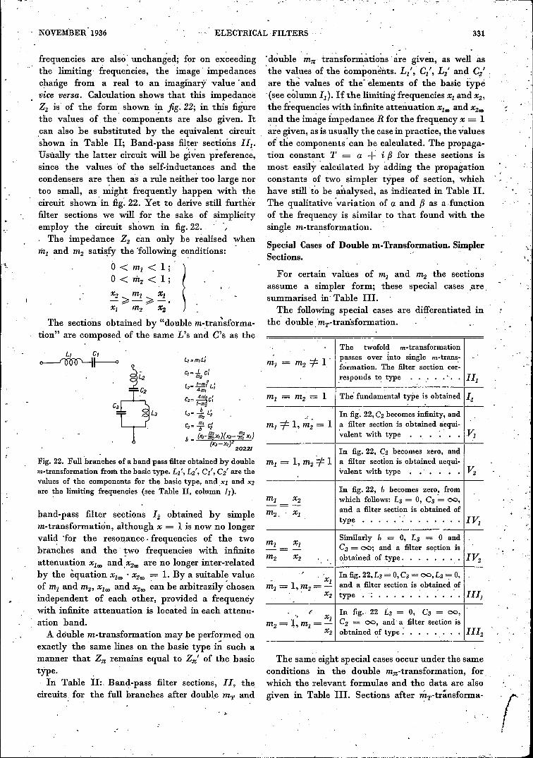
value. The attenuation must therefore be. at least54 decibels. The losses in th~ coils, which it isproposed to use', at frequencies above 1000 cycles/sec, and those of, the condensers throughout the'whole frequency sweep have such values ,thatr ko L = R w C = 0.02. It is further assumedthat the losses in the coils below 1000 cycles/sec .areexclusively due to a D.e. resistance, and are thusindependent of the frequency. Then for 11> 1000cycles/sec, dL = de = 0.02; for 11< 1000 cycles/sec,dL = 0,02·1000/11.
No conditions are laid down for the frequencyband between 900 and 1100 cycles/sec; this istherefore the transition range between the trans-mission and the attenuation bands. The limitingfrequency 'VI is taken in the middle of this band,so that 'VI = 1000 cycles/sec.
Firstly, the type and number of the filter sectionsrequired are determined; this is followed hy thedetermination of the ratings of the filter corn-ponents. In the transmission band required (11= 0.to 900 cycles, i.e. X < 0.9), the attenuation mustbe adequately constant. To satisfy this condition
dB
70
60
50
40
30
20
fa
It is required to design a low-pass filter to 'riteetothe following requirements: The filter is tI? be used 500
-in the anode circuit of a triode with an internal, .
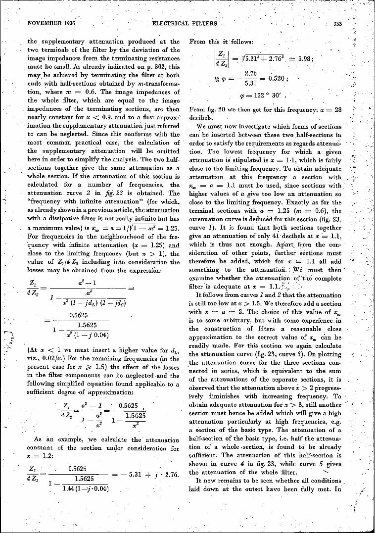
resistance of 10000 ohms. With a constant.alter- 'F' 23 A t' t t f I filt d. . • . . • 19, . ttenua Ion cons an a 0 a ow-pass er composenatmg voltage apphed to. th~ grid of the triode, the .. of four sections, plotted as a function of the frequency,secondary voltage of,the filter must not vary more I. Attenuation of. a section with x",,: = 1.1.than 1 decibel from a specific mean value for 2, Attenuation of both terminal half-sections with m = 0.6frequencies below 900 cycles/seè (the voltage must (x"" = 1.25), which together may be regarded as a single, • section.therefore-be jnaintained hetween 0.89 and 1.12 per 3. Attenuation of a section with x", = 2.0•
.cerrt of this mean value), and for frequencies above 4. Attenuation of a half-section of the basic type., -1100 cycles/sec it must be less than 1/500 of this mean 5•• Total attenuation,. . ' " ,
2
2006/
Vol. 1, No. 11PHILIPS TECHNICAL REVIEW
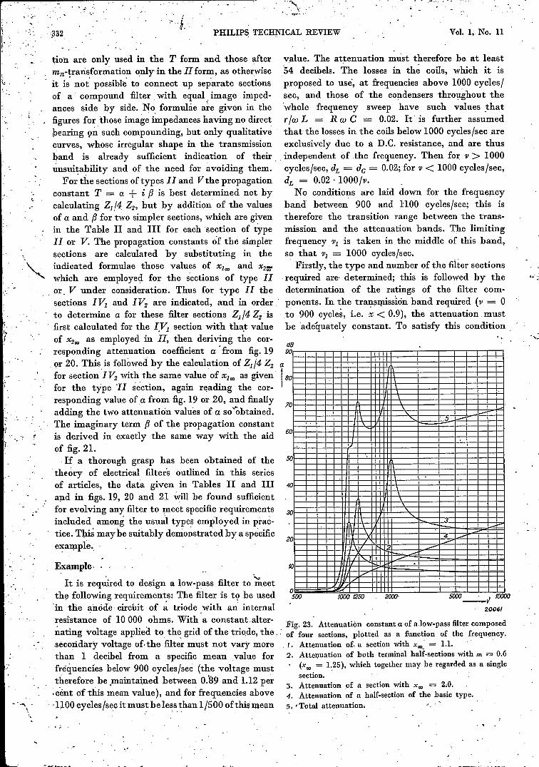
:rHI6H PASS FILTER SECTIONS BAND PASS FILTER SECTIONS I BAND PASS F/LTER SECTIONS1ILOW PASS FILTER SECTIONS,.
1I,1I,IJI,3232·TYPE NUMBER
DOUBLE mT-TRANSFORMATION DOUBLE ml(-TRANSFORMATIONmT -TRANSFORMATION mrt - TRANSFORMATIONBASIC TYPEm, - TRANSFORMATION mI( - TRANSFORMATIONBASIC TYPEmT -TRANSFORMATION mrr-TRANSFORMATIONBASIC TYPEFULL BRANCHES
~C, C
2 0LJ
CJ
L 4m I L', = "Çiij2 I-;x;:, 2
C '-m21i, 2)C •, = 4fiï\'+X'_ 2
L 4m I L'2 = ï7ii? I+X,J 2
C2 .. ~ «+X2~C;
LJ = -In L;
CJ = mC.'
L, s I L'b 2
C, z se;R L, = m,L,'
C, .. .l..C,'m2
L2" e L]
L, = mL,'
C, = -In C,'
L I-m2 r., 2)L'2 Z 4fiï \,+X,_ ,
C - 4m I C'2 _ l-m21+Xz! '
L l-m21. 2)L'3 = "4riï\'+X'" I
C 4m I C'. 3:11: l-m2 I+x,':' '
L,' .: rr~o(X2 -XI)..J!l:l!L./fir ~oR(xrx,)R
41r ~oC/.. ~-,-LI_,""
Ir~o (xrxJR
C,'C, -mC,'
C, .. 7iï"C,' E /flr~, RL, - mL,'L,' _ R~ C,' =-
VALUESL2 .. -fT L;
C2 = cC"
LJ .. .L: LJm2
C, ,., m,e;
C, l-m2e''"4m 2C /fm c:2 - l_m2 IL; .. b4rev,C/.. Irr~,R
OF THEC2 .. 1 C'b'
ELEMENTS _L/L2 = mC2 .. mC;e2 ,., mC>'
CJ = te,'
I', :[\1:\/1o x, I X2 _
ZT= RI/I-y2 (= Zi)
i-M'JzTIR /'- b '---.- ----,,'ZT .. VZ,Z2 V'+4Z2 0 /i
o I
Jz~b,//lo f" 00
ZT z R~'-X2 (= Zr')
o x, 1 X2 00
ZT= R·.Jt-y2(=Zr)
o X,'X2-
Z;zR~
o I 00 ,
ZT = RV'- ~2 (=Z/),
o X_ I 00
ZT'" RVI-fr1-ii2x2
o 1_
Zr'= RV'-~-
:Vj\ ~ol i \_ 1 i 10- X,_X, I X2 )12_ ..
;V:'ol l \;1 /1;1 ~;I ~ ~-DJ;~ ,1
1o(-~ 1 ;f\ -11
Lz.. 0l_Lj_J oL_LU 0 0l__l_U oUU oLVJo I 00 0 I x: 00 0 I x: _ 0 I 00 0 x: I ~,;." 0 x:", f 00 0 x, f X2 00
ATTENUATION
CONSTANTo<.
FOR ELEMENTS
WITHOUT LOSSES
:W01_
PHASE CONSTANT IJ
FOR ELEMENTS
WITHOUT LOSSES
WITHOUTLOSSESd .. O
a2_ f
f-~1
- x2-xl -r T z d.+iIJ IS THE SUM OF THE T's OF TYPES N, and s,WITH THE SAME VALUES X2_ and X,_ ~ESPECTlVELr
Z,4Z2
,f-a2x~~l)(t-ide)
WITHLOSSES'd<tO
r' REPLACE er h- f-idrlxll_Jd,) _ ~J2(xrx~ I-id, L- v xl'-j'de)1- a2
x2(I-id,) (f-j'de)_ 1
x2(I-jd,) ('-jde)- X2 (f-jd,) (1-ide)
i.x z ~o~,
X, z To~2X2 .. 7ö~x,_ = ~o~2_
X?_z To
d,.. retit:I-J..a2 X2.",-X," = a dL::I: rexrX, ;:;r.
a2= _l_ de" _f_I-m2 R,l.Je
DEFINITIONS
"-=r v::»g .. V(x,'-x,,:)(xJ -x,.!)
h =V(f,r !;::)(b- ;2:)• 20'146
.'1Table n. Data for the designs of low-pass. high-pass and band-pass filters.I
t-'.

..,..,",I
"
,I
.~, ..',:/
I
11
; •I
, 'I"'I:' ,I
:\ 11, '
.1
i I'l i.; I
lil\ i
"iIi
·!I'I'I
1I
J;I
\
~"", :~ •zrr:.::;:;'_"c·,,~
NOVEMBER 1936 ELECTRICAL FILTERS
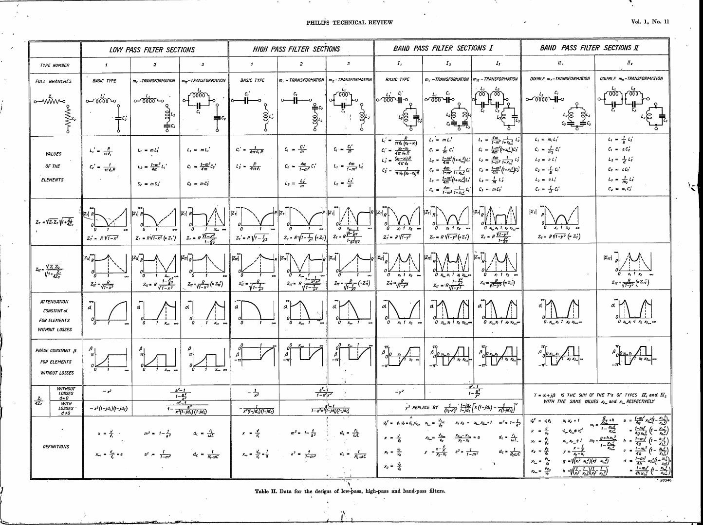
BAND PASS F/LTER SECTIONS1II BAND PASS FILTqR SIiCTIONS1Y BAND PASS FILTER SECTIONS Y
TYPE NUMBERv.][[, PZ, N.,
"'rr- TRANSFORMATION m- - TRANSFORMATION
v,
m7(- rRANSFORMATION
v,
FULL BRANCHES
1,o-I\JWIN'-o
i"VALUES
OF THE
ELEMENTS
mT - TRANSFORMATIONmer - TRANSFORMATIONm; - TRANSFORMATION
L, :a m, L,' L, .. m.L,' L, - .uu: L'I-mi'C, _ I-m/C'
em, 'L, _ ...L L;
m,C, =' m, c/ml;;;:"~ y~m2Z x/m,
00 "!\V' I.\~IZTI " , /:\" , ,\
" 1 1 \0'o x, 1 x,x,~
L, _ .ssu. L 'I-mi'
C, _ I-m/c'4m, ,
L, '"' ...L L;m,C2 == m, c/
L, .. m.L,' L, .. Lt' L, a ~ L/
C, '"' 1jp'cJ
L, '"' ....i9.._ L/I-miC, a .!L C/
9
L2 m J._ L;q
L3 = I L'm2. 2
C3 = C/ .
11TI: ,Ir"'b /~1I I \ Io I I
o x,_x, 1 X2 _
L, z xr' Rrr~o(x,-x,)LR L', .. rr'lo{xrx,J' ' c, '"' ..Lc,'m,
I-m,' L '4m, '4m, C'I-mI'V,2 ,_x/m,
C, = C,' c, '"' .Lc'm, '
ATTENUATION
CONSTANT 0(
FOR ELEMENTS
WITHOUr LOSSES
C, .. ..LC,'m,L2 '"' I-m,' L'
4m, 'C2 ,",4m2 C'
I-ml '
m, ~ • r;;;x::;;TV-x;r::xrm2 lE x/m,
L2 '" L2 - (x2-x,JR L'- 4TT~n z,
L, ..
IZlTï:t. /1\.):\ JI, 1 \0,' 1 I \
o x, I x, 00
1"= Vt~y2(Z ZIT')
L2 '"' at:'
L3 '"' l-m,2 L '~'C3 a ..l!. C,'P
L2 = q L'7f'
I,
PHASE CONSTANT fJ
FOR ELEMENTS
WITHOUT LOSSES
C x,-x, C', ,. 4TT~oR· ,
C2 '"' ITT~o{X, +xûR
m,;:;:
ss: t:'I-mi
.Lc,'q
C2 '"' L3 a L,' .
i{-I .
1
Iz":f'\d1o x,lx2 00
Zr=RVf-y2(= Z:)
C3 z m,C,'
WITHOUTLOSSES
1, dzO4Z2 WITH
LOSSESd*O
001', '1IZTI: \/\/ I
o x, I X2 00
ZT = Rff.? (= Zr')
x2 REPLACE BY x2 (1- jd,) (I-jde) x' REPLACE BY x2 (1- jd,) (I - jde)
(x/-x,3) (x2_x/)(x/-Xi')~,_2_X')
T z d.+ jf3 IS THE SUM OF THE T's OF TYPES LISTED BELOW
WITH THE. SAME VALUES x,_ and X2_
I m, enD2 I [[[2 en JY, I
1"':f\l'I/o x, 1 X2 00
z, z RV t-y' (-Z;)
001'. "1'7' "~I
I" TIR '\,rv" \" I : \o :o x, I X2 X,__
m, en s;
DEFINITIONS
IZ.~I\/No x, f.X2 00
Iz~I/i\/lo x, 1 X2 00
11ITï~t. /1\_)\ .JI 1 I \o / I ',\
. 0 x, 1 X2 00
IZ:!Î\!~ ,/1ol vi ~ Io x,_x, 1 X2 00
x-Ls= x;-=1;
X, x,. 1de __ ,-
RrwC
IzrÇbd]\ /\ Ioo X,IX2 00
ZrZR~(=ZT'}
I .I
;l tlO~o x, 1 X2 X2_00
Table m. Data for the design of special band-pass filters.
Iz;':1 /Nî\ (f1r /' 11,o ~' , I \!o x, I X2 X2:"
20.545
(Xl2 - x,j(x2- x,»(x/- X,1(X2!. - x2
)
• X,2._ ..L.z.:«:x/-x/
x/-x2
x/-xl
.~,x, .. To
x-fy ..--x,-x,
x=..L~o
de .. -I -Re wC
;f\ f:1 ;~ 11oLUlJ 0LJ..U.Jo x, I X2 )(2_~ 0 x,~x, 1 X2 00
:[J__lj'., 'o . 'o x, I X2X2 __
ai, enK,
m, .. ~+hX2_m2. X,_2+ 9
9 z V(x,'- x,j(x/- X,~2)
h zV(b-xb)(f;rx!!)x=-5;",X, =: To"2X2" "D

.,'"
t,
.. i
I .
!r
I~.
f
li'
,~
y
l'
..... . ~., .,
'I
" !
• I •~I.~,Itr
I( •
"~!3:."'::'~ ~_-:. ;-.j -~ .
.... --- .... ,
ê... ;
'" '.
NOVEMBER 1936; .
, ELECTRICAL ,FILTERS' ,..:
the, supplementary attenuation produced at thetwo terminals of the filter by the deviation of theimage impedances from the terminàting resistances, must be small. As already indicated on p. 302, thismay, be achieved by iterminating the 'filter at bothends ~th half-sections obtained by m-transforma-tion, where m = 0.6. The image impedances ofthe whole filter, which are equal to the imageimpedances of the terminating sections, are thennearly constant for x < 0.9, and to a first approx-.imation the supplementary attenuation just referred,to can be neglected. Since this conforms with themost 'common practical case, the calculation of
'the supplementary attenuation will he omittedhere in order to simplify the analysis. The two half-sections together give the same attenuation as awhole section. If the attenuation of this section iscalculated for a number of frequencies, theattenuation curve 2 in fii.23 is obtained. The"frequency with infinite attenuation" (for which,as alreadyshownin a previous article, the attenuationwith a dissipative filter is not really infinite but h~s
, a maximum value) is Xa:> = a = 1nh -- m2 = 1.25.For frequencies in the neighbourhood of the fre-quency with infinite attenuation (x = 1.25) andclose to the limiting frequency (but x > 1), thevalue of Zl/4 Z2 including into consideration thelosses may be obtained from the expression:
a2_1--------~..---------,a2
1x2 (1 -, jdL) (1 - jt}c)
0.56251.5625
1- -;;-.,-------,-----x2 (1 - j 0.04)'1""'."~
t.-, ."
."'t.,,~,. (At x < 1 we must insert a higher value for dL'
viz., O.02/x.) For the remaining frequencies (in thepresent case for x ;;:;:1.5) the effect of the lossesin the filter components can he .neglected and thefollowing simplified equation found applicable to asufficient degree 'of approximation:
0.5625a2 - 1.5625
1-- 1----.·"x2 x2
As an example, we calculate the attenuationconstant of the section under consideration forx = 1.2:
z,- ----------------
4Z2
0.5625. - 5.31 + j .2.76.1.5625
1- -----------1.44(1-:j·0.04)
333
From this it 'follows:
14i21 . V5.312·+ 2.762, .:_ ·5.~8;
, 2.76tg cp = - --- = 0.520 ; ,
5.31 ,
cp = 1520 30' , ..._'
From fig. 20 we then get for this frequency: a - 28decibels.We must now investigate which forms of sections
can' be inserted between these two .half-sections inorde~ to satisfy the requirements as regards attenua- .:tion. The lowest frequency for which a' givenattenuation is stipulated is x = 1,1, which is fairlyclose to the limiting frequency. To obtain adequate. .,.attenuation at this frequency a section withXa:> = a = 1.1 must be used, since sections with ,higher values of a give too low an attenuation so .close to the limiting frequency. Exactly as for theterminal sections with a = 1.25 (m = 0.6), theattenuation curve is deduced for this section (fig. 23,curve 1). It is found that botli, sections togethergive an attenuation of only 41' decibels at x· 1.1,which is thus not enough. Ap'art...from the con-sideration of other points, further séctions musttherefore be added, which for x :_:_1.1 all addsomething to the attenuatioii.': W é must thén :examine whether the attenuation of the completefilter is adequate at x = l.Lr,: -,':,It follows from curves 1 and 2 that the attenuation
is still too low at x > 1.5.We therefore add a sectionwith x = a = 2. The choice of this value of x.;.is to some arbitrary, but with some experience inthe construction of filters a reasonable' closeapproximation to the correct value of Xa:> can hereadily made. For this section we again calculate,the attenuation curve (fig. 23, curve 3). On plottingthe attenuation .curve for the three sections con-nected in series, which is equivalent to the' sumof the attenuations of the separate sections, it isobserved that the attenuation above x > 2 progress-ively diminishes with increasing frequency. Toobtain adequate attenuation for x > 3, still anothersection must hence he added which will give a highattenuation particularly at high frequencies, e.g.a section of the basic type. The attenuation of ahalf-section of the basic type, i.e. half the attenua-tion of a whole -section, is found to be alreadysufficient. The attenuation of this half-section isshown in curve 4 in fig. 23, while curve 5 givesthe attenuation of the whole filter. ' <,
It now remains to be seen whether all conditions ,laid down: at the outset have been fully met. In
-.
.' ~,
, ,
_:....
''_''-:
f _,
t
334 PHILIPS TECHNICAL REVIEW . Vol. 1, No. 11
the'" prescribed transmission band (0 < i < 0.9)the attenuation is between 1 and 3 decibels. Theaverage is 2 decibels, and the attenuation· doesnot vary from this by more than 1 decibel. Therequirements as regards the transmission bandhave thus been met. In -the required attenuation
slightly greater and is then adequate. Above.x > 2the attenuation is indeed reduced, but this is ofno moment since the attenuation in this frequencyband is even then more than enough. The valueseventually arrived at in this analysis correspondto a filter with.x"" = a = 1.8 for this section.
O,955H
~. 9~50iPFI'
o ,0a=t25
O,955H
39550f[LF T
o 0a.t25
20057
Fig. 24: Filter sections for a low-pass filter with a limiting frequency of 1000 cycles/sec.This filter satisfies the requirements set out on p. 336, if the coils and condensers havethe ratings as stated' tliere. . '
band (.x> 1.1) the attenuation hasto be? + 54 =56 decibels. We see that for.x = 1.1 the attenuationis, only 54 decibels; nevertheless this .condition isadequately met for higher frequencies. -In . themajority of practical cases this difference of only2 decibels is quite permissible (being- moreover ina very narrow frequency range). In our case,however, there are several ways available forincreasing the attenuation for .x'= 1.1. For instance,another filter section can be. added, although .thisway out' 'of the difficulty is rather expensiver- alsoat the same time attenuation in the whole attenua-tion range becomes much greater-than is necessary,and the filter becomes unnecessarily bulky andcostly. A usually simpler solution consists in usinga self-inductance of somewhat better quality, i.e.with a slightly lower value for dL = r /Q) L in thesection with a =' 1.1. As a result the attenuationfor.x"" . a'= 1.1 is made much greater. But in the, present case a still simpler solution can be adopted.For the section with.x"" = a. 2 the value 2 wa~selected rather arbitrarily. If a is made 1.9 or 1.8,the attenuation of this section at 'x = 1.1 becomes
'. 'O,955H f,325H 2,645H
20058 '
Fig; 25. Low-pass filter composed of the filter sections givenin fig.: 24.< ,'... •
"."
Finally, it must be' decided whether the varioussections are to be used in the T or the IJ form.As regards attenuation these two forms are identical,only in the one case more coils are required and in,the other more condensers. In general' the circuitwith the smaller number of coils is the less costly, .so that if at all possible the IJ type will be preferredhere, Since, inter alia, a half-section of the fun-damental type occurs, in which there is a spontane-ous transition from IJ sections to T sections, theone terminal half section will correspond to themT-transformation and the other to the mn-trans-formation. ' We thus arrive at the sequence ofsections shown in Jig. 24. The numericàl valuesindicated there for the components are calculatedby the formulae in Table II by inserting R . 10000ohms, and Vj = 1000 cycles/sec. If the individualsections are interconnected and the condensers inparallel are replaced by a single condenser equivalentto the sum of the two, and the self-inductances,;. . r :
in series are also replaced by a single unit equivalentto the pair, then the filter showninfig. 25 is obtained,which, on the secondary side must be terminatedbY,a resistance of 10 000 ohms~,The accuracy with which the scif-inductances
and condensers are calculated a~d calibrated. .must as a rule by so high that the ratings of thefinished filter components do not differ more than1 per ,cent from the theoretical values, Only forfilters which have. to satisfy particularly severerequirements . is a higher degree of accuracynecessary.